EP3698035B1 - Method to determine the needle opening delay of a fuel injector - Google Patents
Method to determine the needle opening delay of a fuel injector Download PDFInfo
- Publication number
- EP3698035B1 EP3698035B1 EP18785925.1A EP18785925A EP3698035B1 EP 3698035 B1 EP3698035 B1 EP 3698035B1 EP 18785925 A EP18785925 A EP 18785925A EP 3698035 B1 EP3698035 B1 EP 3698035B1
- Authority
- EP
- European Patent Office
- Prior art keywords
- needle
- ccft
- value
- ncd
- injector
- Prior art date
- Legal status (The legal status is an assumption and is not a legal conclusion. Google has not performed a legal analysis and makes no representation as to the accuracy of the status listed.)
- Active
Links
Images



Classifications
-
- F—MECHANICAL ENGINEERING; LIGHTING; HEATING; WEAPONS; BLASTING
- F02—COMBUSTION ENGINES; HOT-GAS OR COMBUSTION-PRODUCT ENGINE PLANTS
- F02D—CONTROLLING COMBUSTION ENGINES
- F02D41/00—Electrical control of supply of combustible mixture or its constituents
- F02D41/20—Output circuits, e.g. for controlling currents in command coils
-
- F—MECHANICAL ENGINEERING; LIGHTING; HEATING; WEAPONS; BLASTING
- F02—COMBUSTION ENGINES; HOT-GAS OR COMBUSTION-PRODUCT ENGINE PLANTS
- F02D—CONTROLLING COMBUSTION ENGINES
- F02D41/00—Electrical control of supply of combustible mixture or its constituents
- F02D41/24—Electrical control of supply of combustible mixture or its constituents characterised by the use of digital means
- F02D41/2406—Electrical control of supply of combustible mixture or its constituents characterised by the use of digital means using essentially read only memories
- F02D41/2425—Particular ways of programming the data
- F02D41/2429—Methods of calibrating or learning
- F02D41/2438—Active learning methods
-
- F—MECHANICAL ENGINEERING; LIGHTING; HEATING; WEAPONS; BLASTING
- F02—COMBUSTION ENGINES; HOT-GAS OR COMBUSTION-PRODUCT ENGINE PLANTS
- F02D—CONTROLLING COMBUSTION ENGINES
- F02D41/00—Electrical control of supply of combustible mixture or its constituents
- F02D41/24—Electrical control of supply of combustible mixture or its constituents characterised by the use of digital means
- F02D41/2406—Electrical control of supply of combustible mixture or its constituents characterised by the use of digital means using essentially read only memories
- F02D41/2425—Particular ways of programming the data
- F02D41/2429—Methods of calibrating or learning
- F02D41/2451—Methods of calibrating or learning characterised by what is learned or calibrated
- F02D41/2464—Characteristics of actuators
- F02D41/2467—Characteristics of actuators for injectors
-
- F—MECHANICAL ENGINEERING; LIGHTING; HEATING; WEAPONS; BLASTING
- F02—COMBUSTION ENGINES; HOT-GAS OR COMBUSTION-PRODUCT ENGINE PLANTS
- F02D—CONTROLLING COMBUSTION ENGINES
- F02D41/00—Electrical control of supply of combustible mixture or its constituents
- F02D41/30—Controlling fuel injection
- F02D41/38—Controlling fuel injection of the high pressure type
- F02D41/40—Controlling fuel injection of the high pressure type with means for controlling injection timing or duration
-
- F—MECHANICAL ENGINEERING; LIGHTING; HEATING; WEAPONS; BLASTING
- F02—COMBUSTION ENGINES; HOT-GAS OR COMBUSTION-PRODUCT ENGINE PLANTS
- F02M—SUPPLYING COMBUSTION ENGINES IN GENERAL WITH COMBUSTIBLE MIXTURES OR CONSTITUENTS THEREOF
- F02M51/00—Fuel-injection apparatus characterised by being operated electrically
- F02M51/06—Injectors peculiar thereto with means directly operating the valve needle
-
- F—MECHANICAL ENGINEERING; LIGHTING; HEATING; WEAPONS; BLASTING
- F02—COMBUSTION ENGINES; HOT-GAS OR COMBUSTION-PRODUCT ENGINE PLANTS
- F02D—CONTROLLING COMBUSTION ENGINES
- F02D41/00—Electrical control of supply of combustible mixture or its constituents
- F02D41/20—Output circuits, e.g. for controlling currents in command coils
- F02D2041/2003—Output circuits, e.g. for controlling currents in command coils using means for creating a boost voltage, i.e. generation or use of a voltage higher than the battery voltage, e.g. to speed up injector opening
-
- F—MECHANICAL ENGINEERING; LIGHTING; HEATING; WEAPONS; BLASTING
- F02—COMBUSTION ENGINES; HOT-GAS OR COMBUSTION-PRODUCT ENGINE PLANTS
- F02D—CONTROLLING COMBUSTION ENGINES
- F02D41/00—Electrical control of supply of combustible mixture or its constituents
- F02D41/20—Output circuits, e.g. for controlling currents in command coils
- F02D2041/202—Output circuits, e.g. for controlling currents in command coils characterised by the control of the circuit
- F02D2041/2055—Output circuits, e.g. for controlling currents in command coils characterised by the control of the circuit with means for determining actual opening or closing time
-
- F—MECHANICAL ENGINEERING; LIGHTING; HEATING; WEAPONS; BLASTING
- F02—COMBUSTION ENGINES; HOT-GAS OR COMBUSTION-PRODUCT ENGINE PLANTS
- F02D—CONTROLLING COMBUSTION ENGINES
- F02D2200/00—Input parameters for engine control
- F02D2200/02—Input parameters for engine control the parameters being related to the engine
- F02D2200/06—Fuel or fuel supply system parameters
- F02D2200/0618—Actual fuel injection timing or delay, e.g. determined from fuel pressure drop
-
- F—MECHANICAL ENGINEERING; LIGHTING; HEATING; WEAPONS; BLASTING
- F02—COMBUSTION ENGINES; HOT-GAS OR COMBUSTION-PRODUCT ENGINE PLANTS
- F02D—CONTROLLING COMBUSTION ENGINES
- F02D2200/00—Input parameters for engine control
- F02D2200/02—Input parameters for engine control the parameters being related to the engine
- F02D2200/06—Fuel or fuel supply system parameters
- F02D2200/063—Lift of the valve needle
-
- F—MECHANICAL ENGINEERING; LIGHTING; HEATING; WEAPONS; BLASTING
- F02—COMBUSTION ENGINES; HOT-GAS OR COMBUSTION-PRODUCT ENGINE PLANTS
- F02M—SUPPLYING COMBUSTION ENGINES IN GENERAL WITH COMBUSTIBLE MIXTURES OR CONSTITUENTS THEREOF
- F02M47/00—Fuel-injection apparatus operated cyclically with fuel-injection valves actuated by fluid pressure
- F02M47/02—Fuel-injection apparatus operated cyclically with fuel-injection valves actuated by fluid pressure of accumulator-injector type, i.e. having fuel pressure of accumulator tending to open, and fuel pressure in other chamber tending to close, injection valves and having means for periodically releasing that closing pressure
Definitions
- the invention relates to method to determine the needle opening delay (OD) of a fuel injector.
- the needle opening delay is the time lag between when an activation pulse is sent to fuel injector and the time that the needle starts to move away from its seat to dispense fuel.
- Modern fuel injectors typically use electrical actuators such as piezo or solenoid operated actuators which are used to activate a valve, the valve opening and closing in order to dispense fuel to a combustion chamber via movement of a needle away from a seat.
- an activation pulse of certain duration is sent to the fuel injector to activate the fuel injector via activating the actuator.
- Modern fuel injectors are hydraulically operated in that rather than the actuator actuating the needle directly, the actuator used to operate a valve (system) so as to control pressure in the fuel injector, so as to indirectly operate the fuel injector by movement of a needle to or from a needle seat, using such pressures, so as to selectively dispense fuel.
- actuator operated valve opening and closing and needle opening and closing.
- the opening delay There is typically a time delay between the leading edge of the pulse, i.e. start of activation and the needle valve opening; this is referred to as the opening delay.
- Some designs of fuel injector typically also provide a switch signal, provided often by an extra wire, where a signal on the wire provides means to detect when two moving parts in the injector system are in or out of contact with each other. This may be for example detecting when the valve needle and nozzle/needle seat come into contact or are out of contact with each other, or when the needle after opening (moving away from the valve seat) comes to its end (fully open) stop.
- a switch signal provided often by an extra wire, where a signal on the wire provides means to detect when two moving parts in the injector system are in or out of contact with each other. This may be for example detecting when the valve needle and nozzle/needle seat come into contact or are out of contact with each other, or when the needle after opening (moving away from the valve seat) comes to its end (fully open) stop.
- Many prior art systems use this switch signal to determine the opening time of the injector needle valve or other components. However the use of switch signals which determine the opening time of the needle are sometime unreliable.
- US 2013/312709 A1 describes a method similar to the method of claim 1 without the separate utilisation of a Control Chamber filling time CCFT.
- the invention is a method according to claim 1.
- NCD NCT ⁇ VCT
- NFST and or NCT may be determined from the injector switch signal.
- Said closing time of the solenoid actuated valve may be determined by analyzing the voltage across the solenoid of the solenoid actuated valve and identifying a time of glitch.
- the method may include storing a reference plot of NCD value against the sum Ton, VCD and CCFT for a reference injector, and providing a refined value of opening delay (Refined OD_injx) from the value found from step h) and the data from the reference plot.
- Figure 1 shows a schematic diagram of a solenoid operated fuel injector system which includes a fuel injector 1 (shown in schematic cross section) and includes additional wiring 2 which allows detections of the operational state of the injector.
- the figure shows the ECU portion 3, the harness portion 4 and the injector portion 5.
- the injector portion shows the solenoid 6 of the actuator.
- the additional wiring 5 provides two current paths 7 and 8 to ground as shown depending on the position of the needle.
- the operational state of the injector can be monitored by measuring the voltage on line 9, which allows detection of the state of the needle contacts when it is fully closed fully open and partially open.
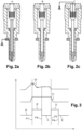
- Figure 2a-c shows three operational states of the fuel injector with reference to the needle position and the current which flows throught the additional wire to ground.
- Figure 2a shows the needle in the closed state A where there is flow of current to ground when the needle contacts the needle seat (bottom contact) - the voltage on line 9 is 0V.
- Figure 2b shows where the needle is partially open in state B and there is no contact with ground through the additional wire and hence no current flow; the voltage on line 9 is high.
- Figure 2c shows the needle when it is in the open position C and there is flow throught the additional wire to ground via the top contact of (the needle is fully open) via pathway 7. The voltage on line 9 is 0V.
- Figure 3 shows the corresponding timeline of the activation pulse 10 sent to the solenoid (top plot), the middle plot shows corresponding timeline of the injection period 11 which is the time from needle opening to closing , and the bottom plot shows the corresponding states of the voltage on the switch signal line 9 with the various opening and closing and intermediate states corresponding to that of figure 2 .
- State A is where the needle is closed, the needle subsequently starts to lift at P1 and the signal on the switch line 9 goes high as there is no current path through the additional wire when the needle is partially open/closed in the transition state B.
- State C is where the needle reaches fully open point P2 and the signal on the switch line 9 goes to zero as current can flow through the additional wire due to the top contact.
- the Needle Falling Start Time at point P3 can be determined. So the figure shows the various states when the needle is in full lift, the top switch is activated and the switch signal goes to 0V. When the needle is travelling back to the seat the short circuit in the top switch disappears and the switch signal is going from 0V to 5V.
- the needle closing time (NCT) is point P4.
- the NFD Needle falling duration can also be computed from the switch signal also and is determined as the period D, between points P3 and P4 in figure 3 .
- Figure 4 shows corresponding timelines of activation pulse 110, valve lift 111, needle command (position) 112 and needle lift 113 respectively.
- the following annotations are used in the figures and description:
- the top plot 110 shows the activation pulse which has a length (duration) of Ton. Underneath is shown the valve lift 111 and shows the valve starts to move/open at point P11 and closes at point P12.
- the assumed VCD is the time between the end of the activation pulse and the time of the VCT.
- the plot 12 below this shows needle effective command and the bottom plot 113 shows the actual movement of the needle and shows a small timespan where the needle lifts to allow injection of fuel and this show a small bell shaped pulse over a timespan of NOL. As can be seen there is a large time span between the start of the activation pulse and the (time the needle starts to lift) opening delay.
- the needle opening delay is determined from the following input parameters:
- an NCD curve function is plotted by providing a plurality of injector operations (cycles) with different activation pulse lengths (Ton). This may be performed using a "sweep" where the fuel injector is activated with e.g. successively increasing pulse activation durations and subsequent measurements of the parameters referred to above. During such a sweep, Ton will increase, and then it will progressively open the valve then the needle. During this sweep, NCD, VCD, CCFT and NOL will progressively increase.
- Ton is the activation pulse duration.
- VCD valve closing delay
- VCT valve closing time
- CCFT NFST - VCT.
- NFST can be determined from the switch signal as described above. So to recap the value of (Ton + VCD + CCFT) is plotted against NCD and is shown in figure 5 as mentioned.
- a line is drawn horizontally on the y-axis (the NCD axis at the CCFT threshold value) i.e. the threshold value of CCFT on the NCD axis and the at this intersect point with the plot on the x-axis is determined as the opening delay OD.
- Figure 6 and 7 shows further plots comparing the values of various parameters for ballistic and non-ballistic (full lift) operations of the fuel injector
- the reference numerals denote the activation pulse (in the case of full lift this is sufficient in length to operate out of ballistic mode) denotes the valve opening state signal denotes the needle signal and shows the needle lift state.
- the full lift CCFT is used.
- the NCD Threshold will be a value dependent on the full lift CCFT.
- NCD will be plotted function of (Ton + VCD + full lift CCFT).
- the full lift CCFT can be calculated as explained above as well as the valve closing time determined e.g. from a glitch in the voltage plot of the solenoid.
- CCFT NFST - VCT, see fig.3
- a stored map of NCD against Ton+VCD+CCFT for an ideal i.e. reference injector can be provided from data recorded on hydraulic rig /from an injection rate measurement device, and can be stored on an ECU.
- Figure 8 shows a graph/plot of (Ton + VCD + CCFT) 20 plotted against NCD for an ideal/reference injector, along with the plot 21 for the injector under test as obtained by the above described method, and shows that determined for the above methodology, the plot for the test injector Inj x 20 should be generally parallel to the curve for the reference injector of Inj Ref . 21. It is again to be noted that data regarding the test injector is not available at low levels.
- NCD is not null (it is very small but not null), it corresponds to the CCFT value for small quantity.
- This delay depends on the hydraulic behaviour of the injector. However this data is usually available. The following method steps are then taken:
- the real OD of the reference injector will be stored as a calibration in the ECU, it will be called OD Ref_map .
- the pseudo OD of the reference injector will also be stored as a calibration dependent on the level of NCD for test injector, it will be called Pseudo_OD Ref_map .
- the difference between (pseudo)OD injx and pseudo_OD ref_map will be added to the OD Ref_map to have the estimated OD of the injx.
- the present invention is an indirect way to determine the OD of a fuel injector.
- the old system was a direct measurement of the needle opening thanks to the switch signal. But this system was sometimes not reliable.
Landscapes
- Engineering & Computer Science (AREA)
- Chemical & Material Sciences (AREA)
- Combustion & Propulsion (AREA)
- Mechanical Engineering (AREA)
- General Engineering & Computer Science (AREA)
- Fuel-Injection Apparatus (AREA)
- Electrical Control Of Air Or Fuel Supplied To Internal-Combustion Engine (AREA)
Description
- The invention relates to method to determine the needle opening delay (OD) of a fuel injector. The needle opening delay is the time lag between when an activation pulse is sent to fuel injector and the time that the needle starts to move away from its seat to dispense fuel.
- Modern fuel injectors typically use electrical actuators such as piezo or solenoid operated actuators which are used to activate a valve, the valve opening and closing in order to dispense fuel to a combustion chamber via movement of a needle away from a seat. Typically an activation pulse of certain duration is sent to the fuel injector to activate the fuel injector via activating the actuator. Modern fuel injectors are hydraulically operated in that rather than the actuator actuating the needle directly, the actuator used to operate a valve (system) so as to control pressure in the fuel injector, so as to indirectly operate the fuel injector by movement of a needle to or from a needle seat, using such pressures, so as to selectively dispense fuel. Thus there is a distinction between actuator operated valve opening and closing, and needle opening and closing.
- There is typically a time delay between the leading edge of the pulse, i.e. start of activation and the needle valve opening; this is referred to as the opening delay.
- Some designs of fuel injector typically also provide a switch signal, provided often by an extra wire, where a signal on the wire provides means to detect when two moving parts in the injector system are in or out of contact with each other. This may be for example detecting when the valve needle and nozzle/needle seat come into contact or are out of contact with each other, or when the needle after opening (moving away from the valve seat) comes to its end (fully open) stop. Many prior art systems use this switch signal to determine the opening time of the injector needle valve or other components. However the use of switch signals which determine the opening time of the needle are sometime unreliable.
-
US 2013/312709 A1 describes a method similar to the method ofclaim 1 without the separate utilisation of a Control Chamber filling time CCFT. - The invention is a method according to
claim 1. - The control chamber filling time is found from the following equation

- The needle closing delay (NCD) is found from the following equation;

- NFST and or NCT may be determined from the injector switch signal.
- Said closing time of the solenoid actuated valve (VCT) may be determined by analyzing the voltage across the solenoid of the solenoid actuated valve and identifying a time of glitch.
- The method may include storing a reference plot of NCD value against the sum Ton, VCD and CCFT for a reference injector, and providing a refined value of opening delay (Refined OD_injx) from the value found from step h) and the data from the reference plot.
- The refined value of opening delay (refined OD_injx) may be determined from the following equation

- where ODinjx is the initial estimate of opening delay found in step j);
- ODref_map is a stored or determined value for a reference injector, representing the sum (Ton + VCD + CCFT) at a zero value of the NCD for the reference injector;
- pseudo_ODref_map is the value of the sum (Ton + VCD + CCFT) at the CCFT threshold value of the NCD with respect to the reference plot.
- The method may include determining for each cycle the needle falling duration (NFD) from steps c) and d); where NFD is determined form the following equation: NFD= NCT-NFST, and wherein a needle closing delay NCD is determined form the following equations NCD= CCFT + NFD
- The present invention is now described by way of example with reference to the accompanying drawings in which:
-
Figure 1 shows a schematic diagram of a solenoid operated fuel injector system -
Figure 2a, 2b, 2c show three operational states of the fuel injector with reference to the needle position and the current which flows throught the additional wire to ground; -
Figure 3 shows the corresponding timeline of the activation pulse sent to the solenoid (top plot), the middle plot shows corresponding timeline of the injection period which is the time from needle opening to closing , and the bottom plot shows the corresponding states of the voltage on the switch signal with the various opening and closing and intermediate states corresponding to that offigure 2 ; -
Figure 4 shows corresponding timelines of activation pulse, valve lift, needle command (position) and needle lift respectively; -
Figure 5 shows the values of the sum of (Ton + VCD + CCFT) plotted against CCFT/NCD; -
Figure 6 and 7 shows further plots comparing the values of various parameters for ballistic and non-ballistic (full lift) operations of the fuel injector; -
Figure 8 illustrates an advanced method of refining the estimated value of opening delay. -
Figure 1 shows a schematic diagram of a solenoid operated fuel injector system which includes a fuel injector 1 (shown in schematic cross section) and includes additional wiring 2 which allows detections of the operational state of the injector. The figure shows theECU portion 3, theharness portion 4 and theinjector portion 5. The injector portion shows thesolenoid 6 of the actuator. Theadditional wiring 5 provides twocurrent paths line 9, which allows detection of the state of the needle contacts when it is fully closed fully open and partially open. -
Figure 2a-c shows three operational states of the fuel injector with reference to the needle position and the current which flows throught the additional wire to ground.Figure 2a shows the needle in the closed state A where there is flow of current to ground when the needle contacts the needle seat (bottom contact) - the voltage online 9 is 0V.Figure 2b shows where the needle is partially open in state B and there is no contact with ground through the additional wire and hence no current flow; the voltage online 9 is high.Figure 2c shows the needle when it is in the open position C and there is flow throught the additional wire to ground via the top contact of (the needle is fully open) viapathway 7. The voltage online 9 is 0V. -
Figure 3 shows the corresponding timeline of theactivation pulse 10 sent to the solenoid (top plot), the middle plot shows corresponding timeline of theinjection period 11 which is the time from needle opening to closing , and the bottom plot shows the corresponding states of the voltage on theswitch signal line 9 with the various opening and closing and intermediate states corresponding to that offigure 2 . State A is where the needle is closed, the needle subsequently starts to lift at P1 and the signal on theswitch line 9 goes high as there is no current path through the additional wire when the needle is partially open/closed in the transition state B. State C is where the needle reaches fully open point P2 and the signal on theswitch line 9 goes to zero as current can flow through the additional wire due to the top contact. As the needle closes (is partially closed) during state D the voltage on the switch line goes high again at point P3 when the needle is in a transition state (partially open) and when the needle hits the needle seat and is closed the switch signal voltage goes to zero at state E at point P4. - So from the state of the switch signal (by monitoring the state of the voltage) the Needle Falling Start Time at point P3 can be determined. So the figure shows the various states when the needle is in full lift, the top switch is activated and the switch signal goes to 0V. When the needle is travelling back to the seat the short circuit in the top switch disappears and the switch signal is going from 0V to 5V. The needle closing time (NCT) is point P4. The NFD: Needle falling duration can also be computed from the switch signal also and is determined as the period D, between points P3 and P4 in
figure 3 . -
Figure 4 shows corresponding timelines ofactivation pulse 110,valve lift 111, needle command (position) 112 andneedle lift 113 respectively. The following annotations are used in the figures and description: - NOT: Needle Opening Time
- NCT: Needle closing time
- VCT: Valve closing time
- NFST: Needle Falling Start Time
- CCFT: Control Chamber filling Time
- OD: Needle Opening Delay
- VCD: valve closing delay
- NCD: Needle Closing Delay
- NOL: needle opening length/duration
- NFD: Needle falling duration
- So the figure shows the corresponding timelines of various parameters in the operation of a solenoid injector. The
top plot 110 shows the activation pulse which has a length (duration) of Ton. Underneath is shown thevalve lift 111 and shows the valve starts to move/open at point P11 and closes at point P12. The assumed VCD is the time between the end of the activation pulse and the time of the VCT. The plot 12 below this shows needle effective command and thebottom plot 113 shows the actual movement of the needle and shows a small timespan where the needle lifts to allow injection of fuel and this show a small bell shaped pulse over a timespan of NOL. As can be seen there is a large time span between the start of the activation pulse and the (time the needle starts to lift) opening delay. The needle falling duration is as shown and is generally over the second half of the NOL. When looking at the plot the following equalities and equations apply:


- In aspects of the invention the needle opening delay is determined from the following input parameters:
- a) The (actuator) valve closing time (VCT). This parameter can be determined from analysis of the current/voltage across the solenoid actuator. Typically when the solenoid valve closes, there is a detectable glitch in the voltage plot which can be preferably determined by looking at the values of dV/dt and or the second derivative. The glitch is determined by observing a point of inflection in the current plot, and such techniques are well known in the art.
- b) The needle closing time (NCT) information can be provided from a switch signal as described above, the time at point P4 at the end of the period D.. This provide the parameter NCT.
- c) The NFD: Needle falling duration. This is computed from the switch signal also and is determined as the period D in
figure 2 , the time duration between point P3 and P4. This is optional and only needed in some embodiments (see *) - d) Injector (actuator) drive pulse length information. (Ton)
- e) CCFT Threshold value. This will be explained in detail hereinafter.
- Using the above information, for a number of injector actuation cycles of different durations of activation pulse, the values of the sum of (Ton + VCD + CCFT) is plotted against NCD.
- The NCD is calculated by NCD = NCT - VCT.
Figure 5 shows such a plot. - (It is to be noted that if in full lift, alternatively NCD may be calculated from the equation NCD=CCFT + NFD) *
The Opening Delay according to aspects is determined by finding the intersection between this curve and the NCD value that corresponds; i.e. is equal to the CCFT threshold value; the later which will be explained hereinafter. So using the above input data, an NCD curve function is plotted by providing a plurality of injector operations (cycles) with different activation pulse lengths (Ton). This may be performed using a "sweep" where the fuel injector is activated with e.g. successively increasing pulse activation durations and subsequent measurements of the parameters referred to above. During such a sweep, Ton will increase, and then it will progressively open the valve then the needle. During this sweep, NCD, VCD, CCFT and NOL will progressively increase. - The value of Ton is the activation pulse duration. The value of VCD (valve closing delay) is determined from VCT (valve closing time), and is the time between the end of the activation pulse and the VCT. CCFT is determined as = NFST - VCT. NFST can be determined from the switch signal as described above. So to recap the value of (Ton + VCD + CCFT) is plotted against NCD and is shown in
figure 5 as mentioned. - As mentioned the threshold value of CCFT is determined; this can be regarded as the maximum CCFT. If CCFT is plotted against pulse length (Ton), the value will increase (during the ballistic range) ) and reach a plateau. This is the CCFT threshold and so this can be determined by looking at the plateau value thereof with increasing pulse length. So to recap CCFT against pulse length (Ton) will go up and reach a plateau and the value at the plateau will be used as the threshold value. The CCFT threshold value can be regarded as a NCD threshold value as will be explained below.
- So to re-iterate, with respect to
figure 5 , a line is drawn horizontally on the y-axis (the NCD axis at the CCFT threshold value) i.e. the threshold value of CCFT on the NCD axis and the at this intersect point with the plot on the x-axis is determined as the opening delay OD. -
Figure 6 and 7 shows further plots comparing the values of various parameters for ballistic and non-ballistic (full lift) operations of the fuel injector the reference numerals denote the activation pulse (in the case of full lift this is sufficient in length to operate out of ballistic mode) denotes the valve opening state signal denotes the needle signal and shows the needle lift state. This illustrates why OD = Ton + VCD + CCFT when NCD = CCFT (it isfigure 4 that illustrates that). As CCFT cannot be measured in ballistic, the full lift CCFT is used. The NCD Threshold will be a value dependent on the full lift CCFT. NCD will be plotted function of (Ton + VCD + full lift CCFT). The full lift CCFT can be calculated as explained above as well as the valve closing time determined e.g. from a glitch in the voltage plot of the solenoid. CCFT = NFST - VCT, seefig.3 - In the above an estimate of the OD is determined. However in order to provide more accurate result, this initial estimate is refined to provide a more accurate estimate. This refined methodology will be explained with reference to
figure 8 . If we refer to the initial estimate as a "pseudo" OD of the injector under test such (Pseudo ODinjx), this will be higher than the real OD (ODinjx) because the NCD Threshold used (full lift CCFT) is higher than the CCFT corresponding to very small quantity (typically 0.1 mg/stroke) Furthermore the data on NCD = (Ton + VCD + CCFT) is not available at low values. Thecurve 21 infigure 8 is that obtained from the above methodology and is the same as infigure 5 . Thus the data or portion of the curve shown dotted ofplot 21 infigure 8 is usually unavailable. - In a refined embodiment there is provided a stored map of NCD against Ton+VCD+CCFT for an ideal i.e. reference injector. This stored (ref injector OD) reference map can be provided from data recorded on hydraulic rig /from an injection rate measurement device, and can be stored on an ECU.
Figure 8 shows a graph/plot of (Ton + VCD + CCFT) 20 plotted against NCD for an ideal/reference injector, along with theplot 21 for the injector under test as obtained by the above described method, and shows that determined for the above methodology, the plot for thetest injector Inj x 20 should be generally parallel to the curve for the reference injector of InjRef. 21. It is again to be noted that data regarding the test injector is not available at low levels. Thus the intersection of the test plot with the X-axis never appears because even for very small quantity, NCD is not null (it is very small but not null), it corresponds to the CCFT value for small quantity. This delay depends on the hydraulic behaviour of the injector. However this data is usually available. The following method steps are then taken: - i) From the reference injector plot, i.e., on the stored map/chart, the 0 (y-axis) crossing is used to get a value of the parameter ODref map zero (where NCD is zero) . As this is fixed, this may be stored on a table.
- ii) Also the current NCD threshold (current threshold CCFT) which is variable and as explained above is used to find initially estimated value of OD for the test injector (Pseudo) OD injx for the test injector is also used to determine the equivalent Pseudo ODref for the reference injector designated Pseudo ODref_map.
- iii) These two parameters are used along with the value of the NCD threshold crossing for the test injector which as previously described is Pseudo OD injx, to get real OD inj x (using the formula) below:

- So in summary the real OD of the reference injector will be stored as a calibration in the ECU, it will be called ODRef_map. The pseudo OD of the reference injector will also be stored as a calibration dependent on the level of NCD for test injector, it will be called Pseudo_ODRef_map. The difference between (pseudo)ODinjx and pseudo_ODref_map will be added to the ODRef_map to have the estimated OD of the injx.
- The present invention is an indirect way to determine the OD of a fuel injector. The old system was a direct measurement of the needle opening thanks to the switch signal. But this system was sometimes not reliable.
Claims (5)
- A method, carried out in an ECU (3), for determining the needle opening delay ODinjx of a solenoid actuated fuel injector (5) thereof, said fuel injector including a solenoid actuated valve (6) adapted to actuate a needle valve, said needle valve comprising a needle adapted to move from an closed state to an open state and to a closed state during an operational cycle of said injector, said needle opening delay being the time between when an activation pulse is sent and when the needle starts to move, comprising the following steps:a) providing, for a series of test injection cycles, respective solenoid actuator drive pulse duration information Ton; for each test injection cycle, performing the following b) to g):b) determining, the closing time of the solenoid actuated valve VCT;c) determining, the needle closing time NCT;d) determining, the needle falling start time NFST;e) determining a Control Chamber filling Time CCFT value from the values determined from step d) and step b), where CCFT = NFST - VCT;f) determining, a needle closing delay NCD from the values at steps b) and c), where NCD = NCT -VCT;g) determining a Valve Closing Delay VCD; said Valve Closing Delay being the time between the end of the drive pulse and the valve closing time;h) providing a test plot by plotting the value of needle closing delay NCD for each cycle against the respective sum of the values of (i) drive pulse duration information Ton, (ii) Valve Closing Delay VCD, and (iii) Control Chamber filling Time CCFT;i) determining a threshold value of CCFT, being the maximum value of CCFT obtainablethrough the use of the series of test injection cycles with different respective drive pulse duration information Ton;j) from the determined plot, determining the value of said sum at the intersect of said plot of the CCFT threshold on the NCD axis;k) determining the opening delay ODinjx as the determined sum value at the intersect.
- A method as claimed in claim 1 where NFST and or NCT are determined from the injector switch signal.
- A method as claimed in claim 1 to 2 wherein said closing time of the solenoid actuated valve VCT is determined by analyzing the voltage across the solenoid of the solenoid actuated valve and identifying a time of glitch from a point of inflection.
- A method as claimed in any preceding claim including storing a reference plot of NCD value against the sum Ton, VCD and CCFT for a reference injector, and providing a refined value of opening delay "refined OD_injx" from the value found from step i) and the data from the reference plot.
- A method as claimed in claim 4 the refined value of opening delay "refined OD_injx"is determined from the following equation
 where ODinjx is the initial estimate of opening delay found in step j);ODref_map is a stored or determined value for a reference injector, representing the sum (Ton + VCD + CCFT) at a zero value of the NCD for the reference injector;pseudo_ODref_map is the value of the sum (Ton + VCD + CCFT) at the CCFT threshold value of the NCD with respect to the reference plot.
Applications Claiming Priority (2)
| Application Number | Priority Date | Filing Date | Title |
|---|---|---|---|
| GB1717099.4A GB2567809B (en) | 2017-10-18 | 2017-10-18 | Method to determine the needle opening delay of a fuel injector |
| PCT/EP2018/077524 WO2019076691A1 (en) | 2017-10-18 | 2018-10-09 | Method to determine the needle opening delay of a fuel injector |
Publications (2)
| Publication Number | Publication Date |
|---|---|
| EP3698035A1 EP3698035A1 (en) | 2020-08-26 |
| EP3698035B1 true EP3698035B1 (en) | 2025-03-26 |
Family
ID=60419419
Family Applications (1)
| Application Number | Title | Priority Date | Filing Date |
|---|---|---|---|
| EP18785925.1A Active EP3698035B1 (en) | 2017-10-18 | 2018-10-09 | Method to determine the needle opening delay of a fuel injector |
Country Status (4)
| Country | Link |
|---|---|
| EP (1) | EP3698035B1 (en) |
| CN (1) | CN111247323B (en) |
| GB (1) | GB2567809B (en) |
| WO (1) | WO2019076691A1 (en) |
Families Citing this family (1)
| Publication number | Priority date | Publication date | Assignee | Title |
|---|---|---|---|---|
| GB2611759B (en) | 2021-10-12 | 2024-03-20 | Delphi Tech Ip Ltd | Method of operating a fuel injection system |
Family Cites Families (8)
| Publication number | Priority date | Publication date | Assignee | Title |
|---|---|---|---|---|
| JP4148134B2 (en) * | 2003-12-19 | 2008-09-10 | 株式会社デンソー | Fuel injection device |
| DE102009029590A1 (en) * | 2009-09-18 | 2011-03-24 | Robert Bosch Gmbh | Method and control device for operating a valve |
| DE102009045469A1 (en) * | 2009-10-08 | 2011-04-14 | Robert Bosch Gmbh | Method and control device for operating a valve |
| DE102010063099A1 (en) * | 2010-12-15 | 2012-06-21 | Robert Bosch Gmbh | Method for operating a Kraftstoffeinspitzanlage an internal combustion engine |
| JP6169404B2 (en) * | 2013-04-26 | 2017-07-26 | 日立オートモティブシステムズ株式会社 | Control device for solenoid valve and control device for internal combustion engine using the same |
| DE102014222556A1 (en) * | 2014-11-05 | 2016-05-12 | Robert Bosch Gmbh | Method for controlling an injection duration of an injector in an internal combustion engine |
| EP3091214B1 (en) * | 2015-05-08 | 2018-11-21 | Continental Automotive GmbH | Monitoring method to monitor the built up of obstructing coatings due to coking in sprayholes of a fuel injector jet nozzle, compensation method to compensate negative effects of these obstructing coatings and electronic control unit for a combustion engine |
| DE102016200743A1 (en) * | 2016-01-20 | 2017-07-20 | Robert Bosch Gmbh | Method for determining an opening delay duration of a fuel injector |
-
2017
- 2017-10-18 GB GB1717099.4A patent/GB2567809B/en active Active
-
2018
- 2018-10-09 CN CN201880067871.1A patent/CN111247323B/en active Active
- 2018-10-09 EP EP18785925.1A patent/EP3698035B1/en active Active
- 2018-10-09 WO PCT/EP2018/077524 patent/WO2019076691A1/en not_active Ceased
Also Published As
| Publication number | Publication date |
|---|---|
| EP3698035A1 (en) | 2020-08-26 |
| WO2019076691A1 (en) | 2019-04-25 |
| GB2567809A (en) | 2019-05-01 |
| GB2567809B (en) | 2020-04-01 |
| CN111247323A (en) | 2020-06-05 |
| GB201717099D0 (en) | 2017-11-29 |
| CN111247323B (en) | 2023-02-21 |
Similar Documents
| Publication | Publication Date | Title |
|---|---|---|
| JP5362039B2 (en) | Method for detecting needle valve closure in a piezo injector | |
| JP2009121482A (en) | Glitch detector and method for detecting glitch event | |
| US8960225B2 (en) | Method for detecting a closing time point of a valve having a coil drive, and valve | |
| US20110180046A1 (en) | Method for operating a fuel injector | |
| US10746119B2 (en) | Pressure determination in a fuel injection valve | |
| KR20140034221A (en) | Solenoid-operated valve and method of monitoring same | |
| EP3698035B1 (en) | Method to determine the needle opening delay of a fuel injector | |
| EP3791058B1 (en) | Method of identifying faults in the operation of hydraulic fuel injectors having accelerometers | |
| EP3124777A1 (en) | Method to determine the coking of a fuel injector | |
| US7743748B2 (en) | Method of controlling the operation of a solenoid | |
| US20100193719A1 (en) | Device and method for controlling an electromagnetic valve | |
| EP4291766B1 (en) | A method of determining closing time of needle valve of a fuel injector | |
| US12129808B2 (en) | Method of determining the opening delay of a fuel injector | |
| KR101990730B1 (en) | How to Monitor the Operation of a Piezo Injector | |
| EP3994348A1 (en) | Method and system to determine the state of needle valve of a fuel injector | |
| US9068526B2 (en) | Method and control unit for operating a valve | |
| KR20210076500A (en) | Method for calculating opening time of an injector and control apparatus for fuel injection of an injector | |
| CN107787400B (en) | Method and device for determining a minimum hydraulic injection interval of a piezo servo injector | |
| EP3347584B1 (en) | Detection method for detecting a gap size of a gap between an injector valve assembly and piezo stack, and actuation method for actuating an actuator unit in a piezo stack | |
| WO2018069376A1 (en) | Method and apparatus to detect impedance of contact between injector valve moving parts | |
| DE102013211489A1 (en) | Method for operating at least one injection valve | |
| EP2930346A1 (en) | Method for the control and diagnosis regarding the operation a fuel injector |
Legal Events
| Date | Code | Title | Description |
|---|---|---|---|
| STAA | Information on the status of an ep patent application or granted ep patent |
Free format text: STATUS: UNKNOWN |
|
| STAA | Information on the status of an ep patent application or granted ep patent |
Free format text: STATUS: THE INTERNATIONAL PUBLICATION HAS BEEN MADE |
|
| PUAI | Public reference made under article 153(3) epc to a published international application that has entered the european phase |
Free format text: ORIGINAL CODE: 0009012 |
|
| STAA | Information on the status of an ep patent application or granted ep patent |
Free format text: STATUS: REQUEST FOR EXAMINATION WAS MADE |
|
| 17P | Request for examination filed |
Effective date: 20200518 |
|
| AK | Designated contracting states |
Kind code of ref document: A1 Designated state(s): AL AT BE BG CH CY CZ DE DK EE ES FI FR GB GR HR HU IE IS IT LI LT LU LV MC MK MT NL NO PL PT RO RS SE SI SK SM TR |
|
| AX | Request for extension of the european patent |
Extension state: BA ME |
|
| DAV | Request for validation of the european patent (deleted) | ||
| DAX | Request for extension of the european patent (deleted) | ||
| STAA | Information on the status of an ep patent application or granted ep patent |
Free format text: STATUS: EXAMINATION IS IN PROGRESS |
|
| 17Q | First examination report despatched |
Effective date: 20221006 |
|
| P01 | Opt-out of the competence of the unified patent court (upc) registered |
Effective date: 20230327 |
|
| RAP1 | Party data changed (applicant data changed or rights of an application transferred) |
Owner name: PHINIA DELPHI LUXEMBOURG SARL |
|
| GRAP | Despatch of communication of intention to grant a patent |
Free format text: ORIGINAL CODE: EPIDOSNIGR1 |
|
| STAA | Information on the status of an ep patent application or granted ep patent |
Free format text: STATUS: GRANT OF PATENT IS INTENDED |
|
| INTG | Intention to grant announced |
Effective date: 20241127 |
|
| GRAS | Grant fee paid |
Free format text: ORIGINAL CODE: EPIDOSNIGR3 |
|
| GRAA | (expected) grant |
Free format text: ORIGINAL CODE: 0009210 |
|
| STAA | Information on the status of an ep patent application or granted ep patent |
Free format text: STATUS: THE PATENT HAS BEEN GRANTED |
|
| AK | Designated contracting states |
Kind code of ref document: B1 Designated state(s): AL AT BE BG CH CY CZ DE DK EE ES FI FR GB GR HR HU IE IS IT LI LT LU LV MC MK MT NL NO PL PT RO RS SE SI SK SM TR |
|
| REG | Reference to a national code |
Ref country code: GB Ref legal event code: FG4D |
|
| REG | Reference to a national code |
Ref country code: CH Ref legal event code: EP |
|
| REG | Reference to a national code |
Ref country code: DE Ref legal event code: R096 Ref document number: 602018080485 Country of ref document: DE |
|
| REG | Reference to a national code |
Ref country code: IE Ref legal event code: FG4D |
|
| PG25 | Lapsed in a contracting state [announced via postgrant information from national office to epo] |
Ref country code: RS Free format text: LAPSE BECAUSE OF FAILURE TO SUBMIT A TRANSLATION OF THE DESCRIPTION OR TO PAY THE FEE WITHIN THE PRESCRIBED TIME-LIMIT Effective date: 20250626 |
|
| PG25 | Lapsed in a contracting state [announced via postgrant information from national office to epo] |
Ref country code: FI Free format text: LAPSE BECAUSE OF FAILURE TO SUBMIT A TRANSLATION OF THE DESCRIPTION OR TO PAY THE FEE WITHIN THE PRESCRIBED TIME-LIMIT Effective date: 20250326 |
|
| REG | Reference to a national code |
Ref country code: LT Ref legal event code: MG9D |
|
| PG25 | Lapsed in a contracting state [announced via postgrant information from national office to epo] |
Ref country code: NO Free format text: LAPSE BECAUSE OF FAILURE TO SUBMIT A TRANSLATION OF THE DESCRIPTION OR TO PAY THE FEE WITHIN THE PRESCRIBED TIME-LIMIT Effective date: 20250626 |
|
| PG25 | Lapsed in a contracting state [announced via postgrant information from national office to epo] |
Ref country code: HR Free format text: LAPSE BECAUSE OF FAILURE TO SUBMIT A TRANSLATION OF THE DESCRIPTION OR TO PAY THE FEE WITHIN THE PRESCRIBED TIME-LIMIT Effective date: 20250326 |
|
| PG25 | Lapsed in a contracting state [announced via postgrant information from national office to epo] |
Ref country code: LV Free format text: LAPSE BECAUSE OF FAILURE TO SUBMIT A TRANSLATION OF THE DESCRIPTION OR TO PAY THE FEE WITHIN THE PRESCRIBED TIME-LIMIT Effective date: 20250326 |
|
| PG25 | Lapsed in a contracting state [announced via postgrant information from national office to epo] |
Ref country code: GR Free format text: LAPSE BECAUSE OF FAILURE TO SUBMIT A TRANSLATION OF THE DESCRIPTION OR TO PAY THE FEE WITHIN THE PRESCRIBED TIME-LIMIT Effective date: 20250627 Ref country code: BG Free format text: LAPSE BECAUSE OF FAILURE TO SUBMIT A TRANSLATION OF THE DESCRIPTION OR TO PAY THE FEE WITHIN THE PRESCRIBED TIME-LIMIT Effective date: 20250326 |
|
| REG | Reference to a national code |
Ref country code: NL Ref legal event code: MP Effective date: 20250326 |
|
| PG25 | Lapsed in a contracting state [announced via postgrant information from national office to epo] |
Ref country code: NL Free format text: LAPSE BECAUSE OF FAILURE TO SUBMIT A TRANSLATION OF THE DESCRIPTION OR TO PAY THE FEE WITHIN THE PRESCRIBED TIME-LIMIT Effective date: 20250326 |
|
| PG25 | Lapsed in a contracting state [announced via postgrant information from national office to epo] |
Ref country code: SE Free format text: LAPSE BECAUSE OF FAILURE TO SUBMIT A TRANSLATION OF THE DESCRIPTION OR TO PAY THE FEE WITHIN THE PRESCRIBED TIME-LIMIT Effective date: 20250326 |
|
| REG | Reference to a national code |
Ref country code: AT Ref legal event code: MK05 Ref document number: 1779182 Country of ref document: AT Kind code of ref document: T Effective date: 20250326 |
|
| PG25 | Lapsed in a contracting state [announced via postgrant information from national office to epo] |
Ref country code: SM Free format text: LAPSE BECAUSE OF FAILURE TO SUBMIT A TRANSLATION OF THE DESCRIPTION OR TO PAY THE FEE WITHIN THE PRESCRIBED TIME-LIMIT Effective date: 20250326 |
|
| PG25 | Lapsed in a contracting state [announced via postgrant information from national office to epo] |
Ref country code: ES Free format text: LAPSE BECAUSE OF FAILURE TO SUBMIT A TRANSLATION OF THE DESCRIPTION OR TO PAY THE FEE WITHIN THE PRESCRIBED TIME-LIMIT Effective date: 20250326 Ref country code: PT Free format text: LAPSE BECAUSE OF FAILURE TO SUBMIT A TRANSLATION OF THE DESCRIPTION OR TO PAY THE FEE WITHIN THE PRESCRIBED TIME-LIMIT Effective date: 20250728 |
|
| PG25 | Lapsed in a contracting state [announced via postgrant information from national office to epo] |
Ref country code: IT Free format text: LAPSE BECAUSE OF FAILURE TO SUBMIT A TRANSLATION OF THE DESCRIPTION OR TO PAY THE FEE WITHIN THE PRESCRIBED TIME-LIMIT Effective date: 20250326 Ref country code: PL Free format text: LAPSE BECAUSE OF FAILURE TO SUBMIT A TRANSLATION OF THE DESCRIPTION OR TO PAY THE FEE WITHIN THE PRESCRIBED TIME-LIMIT Effective date: 20250326 |
|
| PGFP | Annual fee paid to national office [announced via postgrant information from national office to epo] |
Ref country code: GB Payment date: 20250911 Year of fee payment: 8 |
|
| PG25 | Lapsed in a contracting state [announced via postgrant information from national office to epo] |
Ref country code: AT Free format text: LAPSE BECAUSE OF FAILURE TO SUBMIT A TRANSLATION OF THE DESCRIPTION OR TO PAY THE FEE WITHIN THE PRESCRIBED TIME-LIMIT Effective date: 20250326 |
|
| PGFP | Annual fee paid to national office [announced via postgrant information from national office to epo] |
Ref country code: FR Payment date: 20250912 Year of fee payment: 8 |
|
| PG25 | Lapsed in a contracting state [announced via postgrant information from national office to epo] |
Ref country code: EE Free format text: LAPSE BECAUSE OF FAILURE TO SUBMIT A TRANSLATION OF THE DESCRIPTION OR TO PAY THE FEE WITHIN THE PRESCRIBED TIME-LIMIT Effective date: 20250326 |
|
| PG25 | Lapsed in a contracting state [announced via postgrant information from national office to epo] |
Ref country code: RO Free format text: LAPSE BECAUSE OF FAILURE TO SUBMIT A TRANSLATION OF THE DESCRIPTION OR TO PAY THE FEE WITHIN THE PRESCRIBED TIME-LIMIT Effective date: 20250326 |
|
| PG25 | Lapsed in a contracting state [announced via postgrant information from national office to epo] |
Ref country code: SK Free format text: LAPSE BECAUSE OF FAILURE TO SUBMIT A TRANSLATION OF THE DESCRIPTION OR TO PAY THE FEE WITHIN THE PRESCRIBED TIME-LIMIT Effective date: 20250326 |
|
| PG25 | Lapsed in a contracting state [announced via postgrant information from national office to epo] |
Ref country code: IS Free format text: LAPSE BECAUSE OF FAILURE TO SUBMIT A TRANSLATION OF THE DESCRIPTION OR TO PAY THE FEE WITHIN THE PRESCRIBED TIME-LIMIT Effective date: 20250726 |
|
| REG | Reference to a national code |
Ref country code: DE Ref legal event code: R097 Ref document number: 602018080485 Country of ref document: DE |
|
| PGFP | Annual fee paid to national office [announced via postgrant information from national office to epo] |
Ref country code: DE Payment date: 20250912 Year of fee payment: 8 |
|
| PG25 | Lapsed in a contracting state [announced via postgrant information from national office to epo] |
Ref country code: DK Free format text: LAPSE BECAUSE OF FAILURE TO SUBMIT A TRANSLATION OF THE DESCRIPTION OR TO PAY THE FEE WITHIN THE PRESCRIBED TIME-LIMIT Effective date: 20250326 |
|
| PG25 | Lapsed in a contracting state [announced via postgrant information from national office to epo] |
Ref country code: CZ Free format text: LAPSE BECAUSE OF FAILURE TO SUBMIT A TRANSLATION OF THE DESCRIPTION OR TO PAY THE FEE WITHIN THE PRESCRIBED TIME-LIMIT Effective date: 20250326 |
|
| PLBE | No opposition filed within time limit |
Free format text: ORIGINAL CODE: 0009261 |
|
| STAA | Information on the status of an ep patent application or granted ep patent |
Free format text: STATUS: NO OPPOSITION FILED WITHIN TIME LIMIT |
|
| REG | Reference to a national code |
Ref country code: CH Ref legal event code: L10 Free format text: ST27 STATUS EVENT CODE: U-0-0-L10-L00 (AS PROVIDED BY THE NATIONAL OFFICE) Effective date: 20260211 |
|
| 26N | No opposition filed |
Effective date: 20260105 |