EP3697954B1 - Limited conduction heat reflecting materials - Google Patents
Limited conduction heat reflecting materials Download PDFInfo
- Publication number
- EP3697954B1 EP3697954B1 EP18868616.6A EP18868616A EP3697954B1 EP 3697954 B1 EP3697954 B1 EP 3697954B1 EP 18868616 A EP18868616 A EP 18868616A EP 3697954 B1 EP3697954 B1 EP 3697954B1
- Authority
- EP
- European Patent Office
- Prior art keywords
- heat
- elements
- reflecting
- insulating material
- vof
- Prior art date
- Legal status (The legal status is an assumption and is not a legal conclusion. Google has not performed a legal analysis and makes no representation as to the accuracy of the status listed.)
- Active
Links
Images




Classifications
-
- A—HUMAN NECESSITIES
- A41—WEARING APPAREL
- A41D—OUTERWEAR; PROTECTIVE GARMENTS; ACCESSORIES
- A41D31/00—Materials specially adapted for outerwear
- A41D31/04—Materials specially adapted for outerwear characterised by special function or use
- A41D31/06—Thermally protective, e.g. insulating
- A41D31/065—Thermally protective, e.g. insulating using layered materials
-
- A—HUMAN NECESSITIES
- A41—WEARING APPAREL
- A41D—OUTERWEAR; PROTECTIVE GARMENTS; ACCESSORIES
- A41D27/00—Details of garments or of their making
- A41D27/02—Linings
-
- A—HUMAN NECESSITIES
- A41—WEARING APPAREL
- A41D—OUTERWEAR; PROTECTIVE GARMENTS; ACCESSORIES
- A41D31/00—Materials specially adapted for outerwear
- A41D31/02—Layered materials
-
- A—HUMAN NECESSITIES
- A41—WEARING APPAREL
- A41D—OUTERWEAR; PROTECTIVE GARMENTS; ACCESSORIES
- A41D31/00—Materials specially adapted for outerwear
- A41D31/04—Materials specially adapted for outerwear characterised by special function or use
- A41D31/10—Impermeable to liquids, e.g. waterproof; Liquid-repellent
- A41D31/102—Waterproof and breathable
-
- A—HUMAN NECESSITIES
- A43—FOOTWEAR
- A43B—CHARACTERISTIC FEATURES OF FOOTWEAR; PARTS OF FOOTWEAR
- A43B1/00—Footwear characterised by the material
-
- D—TEXTILES; PAPER
- D06—TREATMENT OF TEXTILES OR THE LIKE; LAUNDERING; FLEXIBLE MATERIALS NOT OTHERWISE PROVIDED FOR
- D06N—WALL, FLOOR, OR LIKE COVERING MATERIALS, e.g. LINOLEUM, OILCLOTH, ARTIFICIAL LEATHER, ROOFING FELT, CONSISTING OF A FIBROUS WEB COATED WITH A LAYER OF MACROMOLECULAR MATERIAL; FLEXIBLE SHEET MATERIAL NOT OTHERWISE PROVIDED FOR
- D06N7/00—Flexible sheet materials not otherwise provided for, e.g. textile threads, filaments, yarns or tow, glued on macromolecular material
- D06N7/0097—Web coated with fibres, e.g. flocked
-
- D—TEXTILES; PAPER
- D06—TREATMENT OF TEXTILES OR THE LIKE; LAUNDERING; FLEXIBLE MATERIALS NOT OTHERWISE PROVIDED FOR
- D06Q—DECORATING TEXTILES
- D06Q1/00—Decorating textiles
-
- E—FIXED CONSTRUCTIONS
- E04—BUILDING
- E04H—BUILDINGS OR LIKE STRUCTURES FOR PARTICULAR PURPOSES; SWIMMING OR SPLASH BATHS OR POOLS; MASTS; FENCING; TENTS OR CANOPIES, IN GENERAL
- E04H15/00—Tents or canopies, in general
- E04H15/32—Parts, components, construction details, accessories, interior equipment, specially adapted for tents, e.g. guy-line equipment, skirts, thresholds
- E04H15/54—Covers of tents or canopies
-
- A—HUMAN NECESSITIES
- A41—WEARING APPAREL
- A41D—OUTERWEAR; PROTECTIVE GARMENTS; ACCESSORIES
- A41D2400/00—Functions or special features of garments
- A41D2400/10—Heat retention or warming
-
- A—HUMAN NECESSITIES
- A41—WEARING APPAREL
- A41D—OUTERWEAR; PROTECTIVE GARMENTS; ACCESSORIES
- A41D2500/00—Materials for garments
- A41D2500/10—Knitted
-
- A—HUMAN NECESSITIES
- A41—WEARING APPAREL
- A41D—OUTERWEAR; PROTECTIVE GARMENTS; ACCESSORIES
- A41D2500/00—Materials for garments
- A41D2500/20—Woven
-
- A—HUMAN NECESSITIES
- A41—WEARING APPAREL
- A41D—OUTERWEAR; PROTECTIVE GARMENTS; ACCESSORIES
- A41D2500/00—Materials for garments
- A41D2500/30—Non-woven
-
- A—HUMAN NECESSITIES
- A41—WEARING APPAREL
- A41D—OUTERWEAR; PROTECTIVE GARMENTS; ACCESSORIES
- A41D31/00—Materials specially adapted for outerwear
- A41D31/04—Materials specially adapted for outerwear characterised by special function or use
- A41D31/14—Air permeable, i.e. capable of being penetrated by gases
- A41D31/145—Air permeable, i.e. capable of being penetrated by gases using layered materials
-
- D—TEXTILES; PAPER
- D10—INDEXING SCHEME ASSOCIATED WITH SUBLASSES OF SECTION D, RELATING TO TEXTILES
- D10B—INDEXING SCHEME ASSOCIATED WITH SUBLASSES OF SECTION D, RELATING TO TEXTILES
- D10B2401/00—Physical properties
- D10B2401/02—Moisture-responsive characteristics
-
- D—TEXTILES; PAPER
- D10—INDEXING SCHEME ASSOCIATED WITH SUBLASSES OF SECTION D, RELATING TO TEXTILES
- D10B—INDEXING SCHEME ASSOCIATED WITH SUBLASSES OF SECTION D, RELATING TO TEXTILES
- D10B2403/00—Details of fabric structure established in the fabric forming process
- D10B2403/02—Cross-sectional features
- D10B2403/024—Fabric incorporating additional compounds
-
- D—TEXTILES; PAPER
- D10—INDEXING SCHEME ASSOCIATED WITH SUBLASSES OF SECTION D, RELATING TO TEXTILES
- D10B—INDEXING SCHEME ASSOCIATED WITH SUBLASSES OF SECTION D, RELATING TO TEXTILES
- D10B2501/00—Wearing apparel
- D10B2501/06—Details of garments
-
- Y—GENERAL TAGGING OF NEW TECHNOLOGICAL DEVELOPMENTS; GENERAL TAGGING OF CROSS-SECTIONAL TECHNOLOGIES SPANNING OVER SEVERAL SECTIONS OF THE IPC; TECHNICAL SUBJECTS COVERED BY FORMER USPC CROSS-REFERENCE ART COLLECTIONS [XRACs] AND DIGESTS
- Y10—TECHNICAL SUBJECTS COVERED BY FORMER USPC
- Y10T—TECHNICAL SUBJECTS COVERED BY FORMER US CLASSIFICATION
- Y10T428/00—Stock material or miscellaneous articles
- Y10T428/23907—Pile or nap type surface or component
Definitions
- Embodiments relate to heat reflecting materials, and in particular, to materials that offer improved heat reflective properties and limit heat conduction without compromising breathability.
- WO 2014/120867 A1 discloses a textile product having resilient prominences on at least one surface for improved thermal protection, drag reduction, reduced thermal signature and quick drying. Resilient prominences are regular or random bulges that extend outward from a fabric surface and trap some volume of air or other material therein.
- the present invention is directed to an insulating material as specified in claim 1 and to a method of making an insulating material as specified in claim 11. Preferred embodiments are described in the subclaims. Embodiments of the invention will be readily understood by the following detailed description in conjunction with the accompanying drawings. Embodiments are illustrated by way of example and not by way of limitation in the figures of the accompanying drawings.
- Coupled may mean that two or more elements are in direct physical contact. However, “coupled” may also mean that two or more elements are not in direct contact with each other, but yet still cooperate or interact with each other.
- a phrase in the form "A/B” or in the form “A and/or B” means (A), (B), or (A and B).
- a phrase in the form "at least one of A, B, and C” means (A), (B), (C), (A and B), (A and C), (B and C), or (A, B and C).
- a phrase in the form "(A)B” means (B) or (AB) that is, A is an optional element.
- Embodiments herein provide insulating materials, for example, for body gear and outdoor gear, that provide improved heat reflection and reduced heat conduction, while still providing excellent moisture vapor transmission.
- the insulating materials may include a base material, such as a fabric, having a moisture vapor transmission rate (MVTR) of at least 2000 g/m 2 /24h (JIS 1099 A1), such as at least 4000 g/m 2 /24h (JIS 1099 A1), at least 6000 g/m 2 /24h, or at least 8000 g/m 2 /24h.
- the base material may be a mesh, foam, or leather.
- moisture vapor transmission rate (MVTR) refers to a measure of the passage of water vapor through a material, such as a fabric.
- breathable is used herein to refer to a fabric that has an MVTR at or above 2000 g/m 2 /24h (JIS 1099 A1).
- a breathable material allows for the passage of water vapor, but not liquid water.
- breathable is often assumed to also encompass air permeability, a "breathable" fabric does not necessarily have a high air permeability. Additional desirable characteristics of the base fabric may include water resistance, waterproofness, stretch, drape, and softness.
- a base material can be a woven or non-woven fabric, a knitted fabric, a foam, a mesh, a leather or other material used for the construction of an article of body gear and/or outdoor gear.
- a plurality of heat-reflecting elements may be coupled to a first side of the base material (for example, the side of the material that faces a user's body when the base fabric or other material is incorporated into body gear), and each heat-reflecting element may have a heat-reflecting surface and may be positioned to reflect heat towards a heat source, such as a user's body.
- a plurality of spacer elements may be coupled to the first side of the base material.
- each spacer element may maintain a space, such as an air space, between the first side of the base material, and may prevent or reduce contact between the heat-reflecting elements and an underlying surface, such as a base layer, intermediate layer of clothing, and/or a user's skin, thereby reducing heat conduction through the base material.
- each spacer element may project away from the first side of the base material at least 0.2 - 5.0 mm, such as about 0.2 - 2.0 mm.
- the spacers may take any of a number of forms, and may in some examples be made from woven or non-woven pods, knitted material, foam elements, or vertically oriented fibers (VOF).
- a spacer element made from vertically oriented fibers e.g., a VOF element
- the plurality of spacer elements may at least partially overlay and/or overlap at least some of the plurality of heat-reflecting elements.
- the spacer elements may completely overlap or partially overlap the heat-reflecting elements.
- the spacer elements may cover, overlay, or overlap about 2 - 40% of the surface area of the heat-reflecting elements, such as about 5 - 25%.
- each spacer element may have a maximum dimension of about 1 - 6 mm, such as about 2 -3 mm, and a center-to-center spacing of the spacer elements may be about 3 - 5 mm.
- the spacing and placement of both the heat-reflecting elements and the spacer elements may leave portions of the base material uncovered between adjacent elements, and these uncovered portions of the base material may provide moisture vapor transmission, resulting in a breathable material, such as a breathable fabric.
- a breathable material such as a breathable fabric.
- at least 15% of the base material may remain uncovered by both heat-reflecting elements and spacer elements, such as about 20%, about 30%, about 35%, or about 50%
- the heat-reflecting elements may cover a sufficient surface area of the base material to reflect a desired amount of heat, such as body heat, towards the body of a user, such as at least 30% of the base material.
- the spacer elements may provide enhanced insulation compared to base material alone.
- the spacer elements may prevent or reduce contact between the heat-reflecting elements and an underlying surface, such as the surface of a base layer, or intermediate fabric or material layer, which may in turn reduce heat conduction by the heat-reflecting elements.
- the spacer elements may prevent or reduce contact between the heat-reflecting elements and the skin of a user, which may in turn reduce heat conduction by the heat-reflecting elements.
- the spacer elements also may maintain space between the base material and an underlying surface, such as the surface of a base layer, or intermediate fabric or material layer, which may facilitate air flow and/or ventilation and enhance the sensation of breathability.
- the spacer elements also may maintain space between the skin of a user and the base material, which may facilitate air flow and/or ventilation and enhance the sensation of breathability. Furthermore, the overlapping placement of the spacer elements and the heat-reflecting elements surprisingly does not reduce the amount of heat reflected by the heat-reflecting elements, or reduce the heat reflected as much as expected. In some embodiments, any loss of heat reflection may be more than offset by a corresponding decrease in heat conduction.
- a disclosed insulating material exhibits at least a 50% increase in insulation value over the base material from which it was constructed, for example at least 75%, at least 100%, at least 125%, at least 150%, at least 175%, at least 200%, at least 225% or even at least 250% greater insulation value over the value of the base material from which it was constructed, such as between about 50% and about 230% greater insulation value than the base material from which it was constructed, for example a material that does not include either heat-reflecting elements or spacer elements as described herein.
- the base material such as base fabric
- spacer elements such as vertically oriented fiber elements
- the base material provides greater insulation than the base material alone by a surprising and unexpected amount.
- heat-reflecting elements and spacer elements By adding the spacer elements and the heat-reflecting elements to the base material, heat is trapped and/or retained by the insulating material in a synergistic manner.
- the inclusion of both spacer elements and the heat-reflecting elements to a base fabric has almost a two-fold increase over what would be expected from a simple linear addition of the effect of the spacer elements and the heat-reflecting elements alone. This synergistic effect provides for an insulating material that far exceeds expectations.
- FIGs. 1 , 2 , and 3 illustrate a top view ( FIG. 1 ), a side view ( FIG. 2 ), and a perspective view ( FIG. 3 ) of one example of an insulating material, in accordance with various embodiments.
- the insulating fabric 100 may include a base material 102, such as a base fabric having an MVTR of at least 2000 g/m 2 /24h, which may allow moisture vapor to move away from the user's body and through the base material so as to prevent moisture build up inside the body gear.
- the base material 102 may have one or more additional functional characteristics that are appropriate for its intended use.
- the base material 102 may be made from any material or materials that provides the desired set of functional characteristics, feel, weight, thickness, weave, texture, and/or other desired property, and may include nylon, polyester, rayon, cotton, spandex, wool, silk, or a blend thereof.
- the base material may be a "performance" material, such as a performance synthetic knit or woven material that has a high MVTR (for example, at least 2000 g/m 2 /24h, JIS1099 A1) and an air permeability of above 10-30 CFM on a Frazier device.
- the first side of the base material may be flat for easier application of the heat-reflecting elements and/or spacer elements.
- the insulating material 100 also may include a plurality of heat-reflecting elements 104 coupled to a first side of the base material 102.
- first side refers to the side of the base material 102 that is intended to face the user's body when the base material 102 is incorporated into body gear, whether that side contacts the user's body (such as when the insulating material 100 is used as the innermost or only layer in an article of body gear), or not (such as when the insulating material 100 is incorporated into the article of body gear as an intermediate or outermost layer).
- each heat-reflecting element 104 may have a heat-reflecting surface and may be positioned to reflect heat towards the user's body.
- the term "heat-reflecting element” refers to a unitary element having a surface that reflects electromagnetic radiation having longer wavelengths than those of visible light (e.g., the infrared range, which extends from the nominal red edge of the visible spectrum at 700 nanometers (frequency 430 THz), to 1 mm (300 GHz) for the purpose of this disclosure). This range includes most of the thermal radiation emitted by objects near room temperature.
- the heat-reflecting elements also may reflect electromagnetic radiation in other parts of the spectrum, such as the visible spectrum.
- the heat-reflecting elements are formed from a metallic plastic or a foil, such as a film vacuum-metallized with aluminum.
- Various embodiments may include a film vacuum-metallized with aluminum which is coated with a thin lacquer.
- the thin lacquer overcoat may contain pigments or dyes to modify the reflection of electromagnetic radiation in the visible range, thereby modifying the color of the reflective foil, while at the same time not significantly reducing the reflectance of electromagnetic radiation in the thermal IR range (5 to 35 microns).
- the pigmented foil may be less than 1% lower thermal IR reflectance than the non-pigmented foil, less than 2% lower thermal IR reflectance than the non-pigmented foil, or less than 5% thermal IR reflectance than the non-pigmented foil.
- the heat-reflecting elements may include aluminum, silver, or any other heat-reflecting metal, or more generally, a low-emissivity heat reflective material.
- the heat reflecting elements may have an emissivity of no higher than 0.1, such as no higher than 0.08, no higher than 0.06, or no higher than 0.04.
- the heat-reflecting elements may cover 30-70% of the base material (e.g., the surface area ratio of heat-reflecting elements to base material may be from 7:3 to 3:7), such as 40-60% (e.g., a surface area coverage ratio of from 4:6 to 6:4).
- the heat-reflecting elements may be coupled to the base material with an adhesive.
- the heat-reflecting elements and/or spacer elements may be coupled to the base material with a glue or an adhesive, such as a urethane or acrylate-based adhesive.
- the glue or adhesive may be adsorbent or absorbent, for example to aid in moving moisture outward from the body.
- the heat-reflecting elements may be applied in a pattern or a continuous or discontinuous array, such as a repeating or non-repeating pattern of separate, discrete elements (e.g., dots, rings, lines, stripes, waves, triangles, squares, stars, ovals, or other geometric patterns or shapes, or logos, words, etc.) or a repeating or non-repeating pattern of interconnected elements (such as a lattice).
- a pattern of heat-reflecting elements may be symmetric, ordered, random, and/or asymmetrical. Further, the pattern, size, shape, or spacing of the heat-reflecting elements may differ at strategic locations in the body gear as dictated by the intended use of the article of body gear.
- the size of the heat-reflecting elements may be largest (or the spacing between them may be the smallest) in the core regions of the body for enhanced heat reflection in those areas, and the size of the heat-reflecting elements may be the smallest (or the spacing between them may be the largest) in peripheral areas of the body. In other embodiments, the size of the heat-reflecting elements may be smallest (or the spacing between them may be the largest) in the core regions of the body, and the size of the heat-reflecting elements may be the largest (or the spacing between them may be the smallest) in peripheral areas of the body for enhanced heat reflection in those areas.
- the degree of coverage by the heat-reflecting elements may vary in a gradual fashion over the entire garment as needed for regional heat management. In some embodiments, reducing the area of individual elements, but increasing the density may provide a better balance between heat reflection and base material functionality. In some embodiments, the surface area of individual heat-reflecting elements may be less than 1 cm 2 . In various embodiments, each heat-reflecting element may have a maximum dimension (diameter, hypotenuse, length, width, etc.) that is less than or equal to about 1 cm, such as 4 mm, or 1 mm.
- the insulating material also may include a plurality of vertically oriented fiber (VOF) elements 106 coupled to the first side of the base material 102, and each VOF element 106 may include a plurality of fibers that are oriented substantially perpendicular to the surface of the base material.
- VF element refers to a unitary element having a plurality of substantially perpendicular fibers.
- the VOF elements may be discrete pods that contain a high density of vertically oriented fibers, such as at least 200 VOF fibers for a high denier, fairly coarse fiber.
- the fibers may comprise nylon, polypropylene, or polyester. In various embodiments, the fibers may include nylon, rayon, polyester, and/or cotton fibers.
- the fibers may be wicking fibers in some embodiments. As defined herein, the term "wicking" refers to a fiber that allows transport of a fluid along its length, which for a VOF fiber means generally perpendicular to the plane of the base material.
- the VOF elements and/or the individual fibers may be coupled to the base material with an adhesive. In other embodiments, the VOF fibers may be integrated into the material by embroidering, weaving, or knitting.
- the vertically oriented fibers may have an average length of 0.2 - 2.0 mm, such as about 0.6 mm, and an average linear density of 0.9 - 22 dtex, such as 1.7 dtex.
- the fibers may be selected and arranged to maximize capillary forces between the fibers.
- the VOF elements may be applied in a pattern or a continuous or discontinuous array, such as a repeating or non-repeating pattern of separate, discrete elements (e.g., dots, rings, lines, stripes, waves, triangles, squares, stars, ovals, or other geometric patterns or shapes, or logos, words, etc.) or a repeating or non-repeating pattern of interconnected elements (such as a lattice).
- a pattern of VOF elements may be symmetric, ordered, random, and/or asymmetrical. Further, the pattern, size, shape, or spacing of the VOF elements may differ at strategic locations in the article, such as body gear, as dictated by the intended use of the article.
- At least a portion of the base material remains uncovered between adjacent heat-reflecting elements, and between adjacent VOF elements. Additionally, at least a portion of the base material may remain uncovered between both types of elements, such as at least 10-25%.
- the VOF elements may prevent or reduce contact between the heat reflecting elements and the underlying surface, such as a base layer or body surface.
- the insulating material (including the base material, heat-reflecting elements, and VOF elements) may have a MVTR of at least 2000 g/m 2 /24h (JIS 1099 A1).
- the insulating material may form all or a part of any article, such as used as body or outdoor gear, for example a coat, jacket, shirt, shoe, boot, slipper, base layer, glove, mitten, hat, scarf, pants, sock, tent, backpack or sleeping bag.
- the heat-reflecting elements and the spacer element are positioned on the innermost surface of an article, for example on the innermost surface of a base layer, such as the innermost surface of a base layer facing toward the skin of a subject.
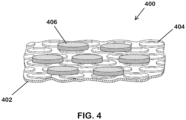
- FIG. 4 illustrates a perspective view of a second example of an insulating material 400, including a base material 402, a plurality of heat-reflecting elements 404, and a plurality of VOF elements 406, in accordance with various embodiments. As illustrated, in some embodiments at least a portion of the VOF elements 406 may overlap with and/or overlay at least a portion of the heat-reflecting elements 404.
- FIG. 5 is a digital image of a third example of an insulating material 500, including a base material 502, a plurality of heat-reflecting elements 504, and a plurality of VOF elements 506; and
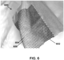
- FIG. 6 is a digital image of a fourth example of an insulating material 600, including a base material 602, a plurality of heat-reflecting elements 604, and a plurality of VOF elements 606, in accordance with various embodiments.
- the VOF elements 606 may include dyed or pigmented fibers.
- FIGS. 7A, 7B, 7C, and 7D are heat escape maps measured with an IR thermal imaging camera, for base material with VOF elements ( FIG. 7A ), base material alone ( FIG. 7B ), base material with heat-reflecting elements ( FIG. 7C ), and base material with heat-reflecting elements and VOF elements ( FIG. 7D ), in accordance with various embodiments. These images were measured on circular material samples (approx. 6.9-cm-diameter) placed face down on an insulated hot plate assembly using a FLIR SC83000 HD Series high speed MWIR megapixel infrared camera.
- the insulated hot plate assembly consisted of a 0.125" thick 6061 aluminum alloy plate as the test surface, which was placed on top of a silicone resistive heating pad (McMaster -Carr p/n 35765K708), which was on top of 2" thick cork insulation.
- the test surface plate had slots cut into it in a rectangular shape to produce a uniform temperature on the test surface.
- a variable transformer was adjusted to provide a steady-state surface temperature. (See, e.g., Incropera, F., DeWitt, D., Bergman, T., and Lavine, A., Fundamentals of Heat and Mass Transfer, 6 th Edition, John Wiley & Sons, 2007.)
- Also disclosed in various embodiments are methods of making an insulating material, which methods generally include coupling a plurality of heat-reflecting elements to a first side of a base material having a moisture vapor transfer rate (MVTR) of at least 2000 g/m 2 /24h (JIS 1099 A1), each of the heat-reflecting elements having a heat-reflecting surface; and coupling a plurality of vertically oriented fiber (VOF) elements to the first side of the base material such that at least some of the plurality of VOF elements at least partially overlay at least some of the plurality of heat-reflecting elements.
- Each VOF element includes a plurality of fibers oriented substantially perpendicular to a surface of the base material.
- the heat-reflecting elements are coupled to the base material before the VOF elements are coupled to the base material.
- the heat-reflecting elements may be permanently coupled to the base material in a variety of ways, including, but not limited to laminating, gluing, heat pressing, printing, or welding, such as by hot air, radiofrequency or ultrasonic welding.
- the plurality of VOF elements may then be coupled to the first side of the base material by screen printing an adhesive followed by electrostatic deposition of short fibers.
- Other methods to add VOF elements include embroidering, weaving and knitting.
- an adhesive such as a single part or two-part catalyzed adhesive may be used to couple the VOF elements to the base material.
- the adhesive may be applied to the base material in a desired pattern using a printing process, and the fibers may then be deposited electrostatically on the base material. Un-adhered fibers may then be removed from the base material by vacuum.
- the fibers may be dispensed from a hopper through a positive electrode grid, which may orient the fibers and accelerate them towards the base material surface.
- a grounded electrode may be positioned under the material surface, and the fibers may be vertically embedded in the adhesive in the areas in which it was applied to the base material, creating a plurality of VOF elements.
- the adhesive may instead be applied to a transfer membrane, and the fibers may be electrostatically embedded in the adhesive on the transfer membrane, creating a plurality of VOF elements.
- the transfer membrane may then be used to apply the VOF elements to the base material.
- the insulating materials described herein may have superior insulating characteristics as compared to other insulating materials, including materials that include heat-reflecting materials without VOF elements.
- Table 1 four different base materials were tested using standard hot plate testing. Samples of the four different base materials were tested in three different configurations: no heat reflecting or VOF elements ("Fabric"), heat-reflecting elements only (“Fabric + heat-reflecting element”), and with both heat-reflecting and VOF elements ("Fabric + heat-reflecting element + vertically oriented fiber").
- heat refers to thermal energy transported due to a temperature gradient (J or Cal).
- heat flux refers to heat rate per unit area.
- thermal transmittance refers to heat flux per unit temperature gradient ( W / m 2 ⁇ K ).
- thermal resistance refers to the reciprocal of thermal transmittance ( m 2 ⁇ K / W ) and clo, which is 0.155 m 2 ⁇ K / W, is a unit of measure for insulation value.
- Dry heat transport data were measured in general accordance with ASTM F1868, Part A- Thermal Resistance. Tests were conducted on 4 different base fabrics, the same fabrics with heat-reflecting elements, and the same materials with heat-reflecting elements plus vertically oriented fiber. The results are shown in Table 1 as the total thermal resistance, R ct , and the thermal resistance of the fabric alone, R cf . These values are given in clo units, and are also known as insulation values. In all cases, the insulation values are lower for the fabric + heat-reflecting element as compared to the same base fabric. When spacer elements (in this case, vertically oriented fiber elements) are added, however, the insulation values were greater than they are for the base fabric and for the fabric + heat-reflecting element by a substantial amount.
- insulation values of the disclosed insulating materials typically exhibit from 50% to 230% greater insulation values than the base materials from which they were constructed.
- Table 2 Area-averaged Temperature from Heat Escape Maps Material Average Backside Surface Temperature (°C) Temperature Difference from Base Material (°C) Fabric (“Base”) 33.4 - Fabric + vertically oriented fiber ("VOF only”) 32.5 0.9 Fabric + heat-reflecting elements (“OHR only”) 32.3 1.1 Fabric + heat-reflecting element + vertically oriented fiber (“OH3D”) 29.7 3.7
- FIG. 7A shows heat escape maps measured with an IR thermal imaging camera, for base fabric with VOF elements ( FIG. 7A ), base fabric alone ( FIG. 7B ), base fabric with heat-reflecting elements ( FIG. 7C ), and base fabric with heat-reflecting elements and VOF elements ( FIG. 7D ), in accordance with various embodiments.
- the circular samples were placed face down on an insulated hot plate assembly set at approximately 37 °C.
- the thermal images were taken of the backside of each of the fabric samples.
- the measured signal is an accurate measure of the temperature of the backside of each fabric, and representative of the amount of heat that escapes through the fabric.
- the base fabric containing heat-reflecting elements + vertically oriented fiber is more insulating than the base fabric by a surprising and unexpected amount.
- By adding vertically oriented fiber to the base fabric sufficient heat is trapped to lower the backside average temperature by 0.9 °C (see Table 2).
- By adding heat-reflecting elements to the base fabric sufficient heat is trapped to lower the backside average temperature by 1.1 °C.
- By adding both elements to the base fabric one might expect the combined effect would lead to a lower temperature of around 2 °C (0.9 °C + 1.1 °C), or even less since the elements overlap. However, the combined effect is nearly twice this amount.
- the combined effect of VOF and heat-reflecting elements traps enough heat to lower the backside average temperature by 3.7 °C.
Landscapes
- Engineering & Computer Science (AREA)
- Textile Engineering (AREA)
- Architecture (AREA)
- Physics & Mathematics (AREA)
- Thermal Sciences (AREA)
- Civil Engineering (AREA)
- Structural Engineering (AREA)
- Laminated Bodies (AREA)
- Thermal Insulation (AREA)
Description
- Embodiments relate to heat reflecting materials, and in particular, to materials that offer improved heat reflective properties and limit heat conduction without compromising breathability.
- Materials that provide improved insulation by reflecting body heat towards the body surface of a wearer often sacrifice moisture vapor transmission and result in low breathability. Such a reduction in moisture vapor transmission may cause the fabric to become damp, thereby causing discomfort and accelerating heat loss through heat conduction. Additionally, contact between heat-reflecting materials and the skin can undesirably allow the heat-reflecting materials to conduct body heat away from the skin, thus inadvertently accelerating heat loss.
WO 2014/120867 A1 discloses a textile product having resilient prominences on at least one surface for improved thermal protection, drag reduction, reduced thermal signature and quick drying. Resilient prominences are regular or random bulges that extend outward from a fabric surface and trap some volume of air or other material therein. - The present invention is directed to an insulating material as specified in claim 1 and to a method of making an insulating material as specified in claim 11. Preferred embodiments are described in the subclaims. Embodiments of the invention will be readily understood by the following detailed description in conjunction with the accompanying drawings. Embodiments are illustrated by way of example and not by way of limitation in the figures of the accompanying drawings.
-
FIG. 1 illustrates a top view of one example of an insulating material, in accordance with various embodiments; -
FIG. 2 illustrates a side view of the insulating material ofFIG. 1 , in accordance with various embodiments; -
FIG. 3 illustrates a perspective view of the insulating material ofFIG. 1 , in accordance with various embodiments; -
FIG. 4 illustrates a perspective view of a second example of an insulating material, in accordance with various embodiments; -
FIG. 5 is a digital image of a third example of an insulating material, in accordance with various embodiments; -
FIG. 6 is a digital image of a fourth example of an insulating material, in accordance with various embodiments; and -
FIGS. 7A, 7B, 7C, and 7D are heat escape maps measured with an infrared (IR) thermal imaging camera, for base fabric with vertically oriented fiber (VOF) elements (FIG. 7A ), base fabric alone (FIG. 7B ), base fabric with heat-reflecting elements (FIG. 7C ), and base fabric with heat-reflecting elements and VOF elements (FIG. 7D ), in accordance with various embodiments. - In the following detailed description, reference is made to the accompanying drawings which form a part hereof, and in which are shown by way of illustration embodiments that may be practiced. It is to be understood that other embodiments may be utilized and structural or logical changes may be made without departing from the scope. Therefore, the following detailed description is not to be taken in a limiting sense, and the scope of embodiments is defined by the appended claims and their equivalents.
- Various operations may be described as multiple discrete operations in turn, in a manner that may be helpful in understanding embodiments; however, the order of description should not be construed to imply that these operations are order dependent.
- The description may use perspective-based descriptions such as up/down, back/front, and top/bottom. Such descriptions are merely used to facilitate the discussion and are not intended to restrict the application of disclosed embodiments.
- The terms "coupled" and "connected," along with their derivatives, may be used. It should be understood that these terms are not intended as synonyms for each other. Rather, in particular embodiments, "connected" may be used to indicate that two or more elements are in direct physical contact with each other. "Coupled" may mean that two or more elements are in direct physical contact. However, "coupled" may also mean that two or more elements are not in direct contact with each other, but yet still cooperate or interact with each other.
- For the purposes of the description, a phrase in the form "A/B" or in the form "A and/or B" means (A), (B), or (A and B). For the purposes of the description, a phrase in the form "at least one of A, B, and C" means (A), (B), (C), (A and B), (A and C), (B and C), or (A, B and C). For the purposes of the description, a phrase in the form "(A)B" means (B) or (AB) that is, A is an optional element.
- The description may use the terms "embodiment" or "embodiments," which may each refer to one or more of the same or different embodiments. Furthermore, the terms "comprising," "including," "having," and the like, as used with respect to embodiments, are synonymous.
- Embodiments herein provide insulating materials, for example, for body gear and outdoor gear, that provide improved heat reflection and reduced heat conduction, while still providing excellent moisture vapor transmission.
- In various embodiments, the insulating materials may include a base material, such as a fabric, having a moisture vapor transmission rate (MVTR) of at least 2000 g/m2/24h (JIS 1099 A1), such as at least 4000 g/m2/24h (JIS 1099 A1), at least 6000 g/m2/24h, or at least 8000 g/m2/24h. In various embodiments, the base material may be a mesh, foam, or leather. As used herein, the term "moisture vapor transmission rate (MVTR)" refers to a measure of the passage of water vapor through a material, such as a fabric. The term "breathable" is used herein to refer to a fabric that has an MVTR at or above 2000 g/m2/24h (JIS 1099 A1). In some embodiments, a breathable material allows for the passage of water vapor, but not liquid water. Although the term "breathable" is often assumed to also encompass air permeability, a "breathable" fabric does not necessarily have a high air permeability. Additional desirable characteristics of the base fabric may include water resistance, waterproofness, stretch, drape, and softness. In embodiments, a base material can be a woven or non-woven fabric, a knitted fabric, a foam, a mesh, a leather or other material used for the construction of an article of body gear and/or outdoor gear.
- In various embodiments, a plurality of heat-reflecting elements may be coupled to a first side of the base material (for example, the side of the material that faces a user's body when the base fabric or other material is incorporated into body gear), and each heat-reflecting element may have a heat-reflecting surface and may be positioned to reflect heat towards a heat source, such as a user's body. Additionally, a plurality of spacer elements may be coupled to the first side of the base material. In various embodiments, each spacer element may maintain a space, such as an air space, between the first side of the base material, and may prevent or reduce contact between the heat-reflecting elements and an underlying surface, such as a base layer, intermediate layer of clothing, and/or a user's skin, thereby reducing heat conduction through the base material.
- In various embodiments, each spacer element may project away from the first side of the base material at least 0.2 - 5.0 mm, such as about 0.2 - 2.0 mm. In various embodiments, the spacers may take any of a number of forms, and may in some examples be made from woven or non-woven pods, knitted material, foam elements, or vertically oriented fibers (VOF). In some embodiments, a spacer element made from vertically oriented fibers (e.g., a VOF element) may include a plurality of fibers that are oriented substantially perpendicular to the surface of the base material. In various embodiments, at least some of the plurality of spacer elements may at least partially overlay and/or overlap at least some of the plurality of heat-reflecting elements. In some embodiments, the spacer elements may completely overlap or partially overlap the heat-reflecting elements. In specific, non-limiting examples, the spacer elements may cover, overlay, or overlap about 2 - 40% of the surface area of the heat-reflecting elements, such as about 5 - 25%. In various embodiments, each spacer element may have a maximum dimension of about 1 - 6 mm, such as about 2 -3 mm, and a center-to-center spacing of the spacer elements may be about 3 - 5 mm.
- In various embodiments, the spacing and placement of both the heat-reflecting elements and the spacer elements may leave portions of the base material uncovered between adjacent elements, and these uncovered portions of the base material may provide moisture vapor transmission, resulting in a breathable material, such as a breathable fabric. In some embodiments, at least 15% of the base material may remain uncovered by both heat-reflecting elements and spacer elements, such as about 20%, about 30%, about 35%, or about 50%, In various embodiments, the heat-reflecting elements may cover a sufficient surface area of the base material to reflect a desired amount of heat, such as body heat, towards the body of a user, such as at least 30% of the base material.
- In various embodiments, the spacer elements may provide enhanced insulation compared to base material alone. In various embodiments, the spacer elements may prevent or reduce contact between the heat-reflecting elements and an underlying surface, such as the surface of a base layer, or intermediate fabric or material layer, which may in turn reduce heat conduction by the heat-reflecting elements. Additionally, in various embodiments, the spacer elements may prevent or reduce contact between the heat-reflecting elements and the skin of a user, which may in turn reduce heat conduction by the heat-reflecting elements. In various embodiments, the spacer elements also may maintain space between the base material and an underlying surface, such as the surface of a base layer, or intermediate fabric or material layer, which may facilitate air flow and/or ventilation and enhance the sensation of breathability. In various embodiments, the spacer elements also may maintain space between the skin of a user and the base material, which may facilitate air flow and/or ventilation and enhance the sensation of breathability. Furthermore, the overlapping placement of the spacer elements and the heat-reflecting elements surprisingly does not reduce the amount of heat reflected by the heat-reflecting elements, or reduce the heat reflected as much as expected. In some embodiments, any loss of heat reflection may be more than offset by a corresponding decrease in heat conduction. In embodiments, a disclosed insulating material exhibits at least a 50% increase in insulation value over the base material from which it was constructed, for example at least 75%, at least 100%, at least 125%, at least 150%, at least 175%, at least 200%, at least 225% or even at least 250% greater insulation value over the value of the base material from which it was constructed, such as between about 50% and about 230% greater insulation value than the base material from which it was constructed, for example a material that does not include either heat-reflecting elements or spacer elements as described herein.
- One of the most significant advantages of the disclosed materials is that the base material, such as base fabric, containing heat-reflecting elements and spacer elements, such as vertically oriented fiber elements, provides greater insulation than the base material alone by a surprising and unexpected amount. By adding the spacer elements and the heat-reflecting elements to the base material, heat is trapped and/or retained by the insulating material in a synergistic manner. As demonstrated in the Example below, and as specifically shown in Table 2, the inclusion of both spacer elements and the heat-reflecting elements to a base fabric has almost a two-fold increase over what would be expected from a simple linear addition of the effect of the spacer elements and the heat-reflecting elements alone. This synergistic effect provides for an insulating material that far exceeds expectations.
-
FIGs. 1 ,2 , and3 illustrate a top view (FIG. 1 ), a side view (FIG. 2 ), and a perspective view (FIG. 3 ) of one example of an insulating material, in accordance with various embodiments. With reference toFIGs. 1 ,2 , and3 , the insulatingfabric 100 may include abase material 102, such as a base fabric having an MVTR of at least 2000 g/m2/24h, which may allow moisture vapor to move away from the user's body and through the base material so as to prevent moisture build up inside the body gear. Additionally, thebase material 102 may have one or more additional functional characteristics that are appropriate for its intended use. Thebase material 102 may be made from any material or materials that provides the desired set of functional characteristics, feel, weight, thickness, weave, texture, and/or other desired property, and may include nylon, polyester, rayon, cotton, spandex, wool, silk, or a blend thereof. In specific, non-limiting embodiments, the base material may be a "performance" material, such as a performance synthetic knit or woven material that has a high MVTR (for example, at least 2000 g/m2/24h, JIS1099 A1) and an air permeability of above 10-30 CFM on a Frazier device. In some embodiments, the first side of the base material may be flat for easier application of the heat-reflecting elements and/or spacer elements. - With continued reference to
FIGs. 1 ,2 , and3 , the insulatingmaterial 100 also may include a plurality of heat-reflectingelements 104 coupled to a first side of thebase material 102. As used herein, the term "first side" refers to the side of thebase material 102 that is intended to face the user's body when thebase material 102 is incorporated into body gear, whether that side contacts the user's body (such as when the insulatingmaterial 100 is used as the innermost or only layer in an article of body gear), or not (such as when the insulatingmaterial 100 is incorporated into the article of body gear as an intermediate or outermost layer). In various embodiments, each heat-reflectingelement 104 may have a heat-reflecting surface and may be positioned to reflect heat towards the user's body. - As used herein, the term "heat-reflecting element" refers to a unitary element having a surface that reflects electromagnetic radiation having longer wavelengths than those of visible light (e.g., the infrared range, which extends from the nominal red edge of the visible spectrum at 700 nanometers (frequency 430 THz), to 1 mm (300 GHz) for the purpose of this disclosure). This range includes most of the thermal radiation emitted by objects near room temperature. In various embodiments, the heat-reflecting elements also may reflect electromagnetic radiation in other parts of the spectrum, such as the visible spectrum. In various embodiments, the heat-reflecting elements are formed from a metallic plastic or a foil, such as a film vacuum-metallized with aluminum. Various embodiments may include a film vacuum-metallized with aluminum which is coated with a thin lacquer. In various embodiments, the thin lacquer overcoat may contain pigments or dyes to modify the reflection of electromagnetic radiation in the visible range, thereby modifying the color of the reflective foil, while at the same time not significantly reducing the reflectance of electromagnetic radiation in the thermal IR range (5 to 35 microns). For example, the pigmented foil may be less than 1% lower thermal IR reflectance than the non-pigmented foil, less than 2% lower thermal IR reflectance than the non-pigmented foil, or less than 5% thermal IR reflectance than the non-pigmented foil. Generally, the heat-reflecting elements may include aluminum, silver, or any other heat-reflecting metal, or more generally, a low-emissivity heat reflective material. In particular embodiments, the heat reflecting elements may have an emissivity of no higher than 0.1, such as no higher than 0.08, no higher than 0.06, or no higher than 0.04.
- In various embodiments, the heat-reflecting elements may cover 30-70% of the base material (e.g., the surface area ratio of heat-reflecting elements to base material may be from 7:3 to 3:7), such as 40-60% (e.g., a surface area coverage ratio of from 4:6 to 6:4). In various embodiments, the heat-reflecting elements may be coupled to the base material with an adhesive. In various embodiments, the heat-reflecting elements and/or spacer elements may be coupled to the base material with a glue or an adhesive, such as a urethane or acrylate-based adhesive. In some embodiments, the glue or adhesive may be adsorbent or absorbent, for example to aid in moving moisture outward from the body.
- In various embodiments, the heat-reflecting elements may be applied in a pattern or a continuous or discontinuous array, such as a repeating or non-repeating pattern of separate, discrete elements (e.g., dots, rings, lines, stripes, waves, triangles, squares, stars, ovals, or other geometric patterns or shapes, or logos, words, etc.) or a repeating or non-repeating pattern of interconnected elements (such as a lattice). In various embodiments, a pattern of heat-reflecting elements may be symmetric, ordered, random, and/or asymmetrical. Further, the pattern, size, shape, or spacing of the heat-reflecting elements may differ at strategic locations in the body gear as dictated by the intended use of the article of body gear.
- In various embodiments, the size of the heat-reflecting elements may be largest (or the spacing between them may be the smallest) in the core regions of the body for enhanced heat reflection in those areas, and the size of the heat-reflecting elements may be the smallest (or the spacing between them may be the largest) in peripheral areas of the body. In other embodiments, the size of the heat-reflecting elements may be smallest (or the spacing between them may be the largest) in the core regions of the body, and the size of the heat-reflecting elements may be the largest (or the spacing between them may be the smallest) in peripheral areas of the body for enhanced heat reflection in those areas. In some embodiments, the degree of coverage by the heat-reflecting elements may vary in a gradual fashion over the entire garment as needed for regional heat management. In some embodiments, reducing the area of individual elements, but increasing the density may provide a better balance between heat reflection and base material functionality. In some embodiments, the surface area of individual heat-reflecting elements may be less than 1 cm2. In various embodiments, each heat-reflecting element may have a maximum dimension (diameter, hypotenuse, length, width, etc.) that is less than or equal to about 1 cm, such as 4 mm, or 1 mm.
- With continued reference to
FIGs.1 ,2 , and3 , in certain specific, non-limiting examples, the insulating material also may include a plurality of vertically oriented fiber (VOF)elements 106 coupled to the first side of thebase material 102, and eachVOF element 106 may include a plurality of fibers that are oriented substantially perpendicular to the surface of the base material. As used herein, the term "VOF element" refers to a unitary element having a plurality of substantially perpendicular fibers. In various embodiments, the VOF elements may be discrete pods that contain a high density of vertically oriented fibers, such as at least 200 VOF fibers for a high denier, fairly coarse fiber. In various embodiments, the fibers may comprise nylon, polypropylene, or polyester. In various embodiments, the fibers may include nylon, rayon, polyester, and/or cotton fibers. The fibers may be wicking fibers in some embodiments. As defined herein, the term "wicking" refers to a fiber that allows transport of a fluid along its length, which for a VOF fiber means generally perpendicular to the plane of the base material. In various embodiments, the VOF elements and/or the individual fibers may be coupled to the base material with an adhesive. In other embodiments, the VOF fibers may be integrated into the material by embroidering, weaving, or knitting. - In various embodiments, the vertically oriented fibers may have an average length of 0.2 - 2.0 mm, such as about 0.6 mm, and an average linear density of 0.9 - 22 dtex, such as 1.7 dtex. In various embodiments, the fibers may be selected and arranged to maximize capillary forces between the fibers.
- The VOF elements may be applied in a pattern or a continuous or discontinuous array, such as a repeating or non-repeating pattern of separate, discrete elements (e.g., dots, rings, lines, stripes, waves, triangles, squares, stars, ovals, or other geometric patterns or shapes, or logos, words, etc.) or a repeating or non-repeating pattern of interconnected elements (such as a lattice). In various embodiments, a pattern of VOF elements may be symmetric, ordered, random, and/or asymmetrical. Further, the pattern, size, shape, or spacing of the VOF elements may differ at strategic locations in the article, such as body gear, as dictated by the intended use of the article.
- In various embodiments, at least a portion of the base material remains uncovered between adjacent heat-reflecting elements, and between adjacent VOF elements. Additionally, at least a portion of the base material may remain uncovered between both types of elements, such as at least 10-25%.
- In various embodiments, the VOF elements may prevent or reduce contact between the heat reflecting elements and the underlying surface, such as a base layer or body surface. In various embodiments, the insulating material (including the base material, heat-reflecting elements, and VOF elements) may have a MVTR of at least 2000 g/m2/24h (JIS 1099 A1). The insulating material may form all or a part of any article, such as used as body or outdoor gear, for example a coat, jacket, shirt, shoe, boot, slipper, base layer, glove, mitten, hat, scarf, pants, sock, tent, backpack or sleeping bag. In certain embodiments the heat-reflecting elements and the spacer element are positioned on the innermost surface of an article, for example on the innermost surface of a base layer, such as the innermost surface of a base layer facing toward the skin of a subject.
-
FIG. 4 illustrates a perspective view of a second example of an insulatingmaterial 400, including abase material 402, a plurality of heat-reflectingelements 404, and a plurality ofVOF elements 406, in accordance with various embodiments. As illustrated, in some embodiments at least a portion of theVOF elements 406 may overlap with and/or overlay at least a portion of the heat-reflectingelements 404. -
FIG. 5 is a digital image of a third example of an insulatingmaterial 500, including abase material 502, a plurality of heat-reflectingelements 504, and a plurality ofVOF elements 506; andFIG. 6 is a digital image of a fourth example of an insulatingmaterial 600, including abase material 602, a plurality of heat-reflectingelements 604, and a plurality ofVOF elements 606, in accordance with various embodiments. In some embodiments, theVOF elements 606 may include dyed or pigmented fibers. -
FIGS. 7A, 7B, 7C, and 7D are heat escape maps measured with an IR thermal imaging camera, for base material with VOF elements (FIG. 7A ), base material alone (FIG. 7B ), base material with heat-reflecting elements (FIG. 7C ), and base material with heat-reflecting elements and VOF elements (FIG. 7D ), in accordance with various embodiments. These images were measured on circular material samples (approx. 6.9-cm-diameter) placed face down on an insulated hot plate assembly using a FLIR SC83000 HD Series high speed MWIR megapixel infrared camera. The insulated hot plate assembly consisted of a 0.125" thick 6061 aluminum alloy plate as the test surface, which was placed on top of a silicone resistive heating pad (McMaster -Carr p/n 35765K708), which was on top of 2" thick cork insulation. The test surface plate had slots cut into it in a rectangular shape to produce a uniform temperature on the test surface. The test surface was also painted matte black to approximate the emissivity of skin (εskin = 0.95 ≈ εblack paint (Parsons) = 0.98). A variable transformer was adjusted to provide a steady-state surface temperature. (See, e.g., Incropera, F., DeWitt, D., Bergman, T., and Lavine, A., Fundamentals of Heat and Mass Transfer, 6th Edition, John Wiley & Sons, 2007.) - Also disclosed in various embodiments are methods of making an insulating material, which methods generally include coupling a plurality of heat-reflecting elements to a first side of a base material having a moisture vapor transfer rate (MVTR) of at least 2000 g/m2/24h (JIS 1099 A1), each of the heat-reflecting elements having a heat-reflecting surface; and coupling a plurality of vertically oriented fiber (VOF) elements to the first side of the base material such that at least some of the plurality of VOF elements at least partially overlay at least some of the plurality of heat-reflecting elements. Each VOF element includes a plurality of fibers oriented substantially perpendicular to a surface of the base material.
- In various embodiments, the heat-reflecting elements are coupled to the base material before the VOF elements are coupled to the base material. The heat-reflecting elements may be permanently coupled to the base material in a variety of ways, including, but not limited to laminating, gluing, heat pressing, printing, or welding, such as by hot air, radiofrequency or ultrasonic welding.
- In various embodiments, the plurality of VOF elements may then be coupled to the first side of the base material by screen printing an adhesive followed by electrostatic deposition of short fibers. Other methods to add VOF elements include embroidering, weaving and knitting. For instance, in some embodiments, an adhesive, such as a single part or two-part catalyzed adhesive may be used to couple the VOF elements to the base material. The adhesive may be applied to the base material in a desired pattern using a printing process, and the fibers may then be deposited electrostatically on the base material. Un-adhered fibers may then be removed from the base material by vacuum.
- In one specific, non-limiting example, the fibers may be dispensed from a hopper through a positive electrode grid, which may orient the fibers and accelerate them towards the base material surface. A grounded electrode may be positioned under the material surface, and the fibers may be vertically embedded in the adhesive in the areas in which it was applied to the base material, creating a plurality of VOF elements.
- In another specific, non-limiting example, the adhesive may instead be applied to a transfer membrane, and the fibers may be electrostatically embedded in the adhesive on the transfer membrane, creating a plurality of VOF elements. The transfer membrane may then be used to apply the VOF elements to the base material.
- In various embodiments, the insulating materials described herein may have superior insulating characteristics as compared to other insulating materials, including materials that include heat-reflecting materials without VOF elements. As shown in Table 1 below, four different base materials were tested using standard hot plate testing. Samples of the four different base materials were tested in three different configurations: no heat reflecting or VOF elements ("Fabric"), heat-reflecting elements only ("Fabric + heat-reflecting element"), and with both heat-reflecting and VOF elements ("Fabric + heat-reflecting element + vertically oriented fiber"). Heat flux (W) and dry heat transfer rate (W/ m2 °C) were measured, and an average insulation value (clo = 0.155 K·m2·W-1) was calculated for each. As used herein, the term "heat" refers to thermal energy transported due to a temperature gradient (J or Cal). As used herein, the term "heat rate" refers to thermal energy transported per unit time (J/s = W). As used herein, the term "heat flux" refers to heat rate per unit area. As used herein, the term "thermal transmittance" refers to heat flux per unit temperature gradient (W/m2·K). As used herein, the term "thermal resistance" refers to the reciprocal of thermal transmittance (m2·K/W) and clo, which is 0.155 m2·K/W, is a unit of measure for insulation value. The results of testing of specific examples of limited conduction heat reflective materials is shown below in Table 1.
Table 1: Thermal Resistance Data Measured Using Standard Hotplate Testing Fabric Fabric + heat-reflecting element Fabric + heat-reflecting element + vertically oriented fiber Base fabric 053165 Total thermal resistance, Rct (clo)1 0.423 ± 0.003 0.403 ± 0.003 0.467 ± 0.003 Thermal resistance of the fabric alone, Rcf (clo) 0.068 ± 0.004 0.048 ± 0.003 0.112 ± 0.009 Base fabric 033770 Total thermal resistance, Rct (clo)1 0.478 ± 0.010 0.425 ± 0.015 0.484 ± 0.008 Thermal resistance of the fabric alone, Rcf (clo) 0.123 ± 0.011 0.070 ± 0.015 0.129 ± 0.008 Base fabric 031908 Total thermal 0.387 ± 0.013 0.376 ± 0.007 0.455 ± 0.011 resistance, Rct (clo)1 Thermal resistance of the fabric alone, Rcf (clo) 0.032 ± 0.013 0.021 ± 0.007 0.100 ± 0.011 Base fabric 060360 Total thermal resistance, Rct (clo)2 0.560 ± 0.033 0.559 ± 0.007 0.668 ± 0.015 Thermal resistance of the fabric alone, Rcf (clo) 0.047 0.046 0.155 1Bare plate thermal resistance, Rcbp (clo) = 0.353 ± 0.002
2Bare plate thermal resistance, Rcbp (clo) = 0.514 (no standard deviation provided) - Dry heat transport data were measured in general accordance with ASTM F1868, Part A- Thermal Resistance. Tests were conducted on 4 different base fabrics, the same fabrics with heat-reflecting elements, and the same materials with heat-reflecting elements plus vertically oriented fiber. The results are shown in Table 1 as the total thermal resistance, Rct, and the thermal resistance of the fabric alone, Rcf. These values are given in clo units, and are also known as insulation values. In all cases, the insulation values are lower for the fabric + heat-reflecting element as compared to the same base fabric. When spacer elements (in this case, vertically oriented fiber elements) are added, however, the insulation values were greater than they are for the base fabric and for the fabric + heat-reflecting element by a substantial amount. Depending on the specific base material, insulation values of the disclosed insulating materials typically exhibit from 50% to 230% greater insulation values than the base materials from which they were constructed.
Table 2. Area-averaged Temperature from Heat Escape Maps Material Average Backside Surface Temperature (°C) Temperature Difference from Base Material (°C) Fabric ("Base") 33.4 - Fabric + vertically oriented fiber ("VOF only") 32.5 0.9 Fabric + heat-reflecting elements ("OHR only") 32.3 1.1 Fabric + heat-reflecting element + vertically oriented fiber ("OH3D") 29.7 3.7 -
Figures 7A, 7B, 7C, and 7B show heat escape maps measured with an IR thermal imaging camera, for base fabric with VOF elements (FIG. 7A ), base fabric alone (FIG. 7B ), base fabric with heat-reflecting elements (FIG. 7C ), and base fabric with heat-reflecting elements and VOF elements (FIG. 7D ), in accordance with various embodiments. The circular samples were placed face down on an insulated hot plate assembly set at approximately 37 °C. The thermal images were taken of the backside of each of the fabric samples. Thus, for the fabric samples that contain VOF, heat-reflecting elements, or both, these features face toward the hot plate and therefore cannot affect the sample emissivity toward the infrared camera. As a result, the measured signal is an accurate measure of the temperature of the backside of each fabric, and representative of the amount of heat that escapes through the fabric. - Area-averaged temperatures from the heat escape maps of
Figure 7 are shown in Table 2. The highest average temperature, and the temperature closest to the temperature of the hot plate, is 33.4 °C for the base fabric. Thus, the most heat escapes through the base fabric, which is the least insulating of the four fabrics measured. The next highest average temperature is 32.5 °C for the base fabric + vertically oriented fiber ("VOF only"), followed by 32.3 °C for the base fabric + heat-reflecting elements ("OHR only"). The lowest average temperature is 29.7 °C for the base fabric + heat-reflecting elements + vertically oriented fiber ("OH3D"). Thus, the least amount of heat escapes through this fabric, which is the most insulating of the four fabrics measured. - Most significantly, the base fabric containing heat-reflecting elements + vertically oriented fiber is more insulating than the base fabric by a surprising and unexpected amount. By adding vertically oriented fiber to the base fabric, sufficient heat is trapped to lower the backside average temperature by 0.9 °C (see Table 2). By adding heat-reflecting elements to the base fabric, sufficient heat is trapped to lower the backside average temperature by 1.1 °C. By adding both elements to the base fabric, one might expect the combined effect would lead to a lower temperature of around 2 °C (0.9 °C + 1.1 °C), or even less since the elements overlap. However, the combined effect is nearly twice this amount. The combined effect of VOF and heat-reflecting elements traps enough heat to lower the backside average temperature by 3.7 °C.
- Although certain embodiments have been illustrated and described herein, it will be appreciated by those of ordinary skill in the art that a wide variety of alternate and/or equivalent embodiments or implementations calculated to achieve the same purposes may be substituted for the embodiments shown and described without departing from the scope. Those with skill in the art will readily appreciate that embodiments may be implemented in a very wide variety of ways.
Claims (13)
- An insulating material comprising:a base fabric having a moisture vapor transfer rate (MVTR) of at least 2000 g/m2/24h measured in accordance with JIS 1099 A1;a plurality of heat-reflecting elements coupled to a first side of the base fabric, wherein the first side of the base fabric is an innermost surface of the base fabric, each heat-reflecting element having a heat-reflecting surface positioned to reflect heat towards a wearer of the insulating material; anda plurality of spacer elements, wherein at least some of the plurality of spacer elements at least partially overlay the heat-reflecting surfaces of at least some of the plurality of heat-reflecting elements, the at least some of the plurality of spacer elements attached to and extending from the first side of the base fabric and from the heat-reflecting surfaces to be directed toward and exposed to contact by the wearer of the insulating material, each spacer element sized and shaped to reduce contact of the heat-reflecting elements with an underlying surface or with the wearer,wherein the spacer elements comprise foam pods or pods comprising, woven, nonwoven or knitted materials or vertically oriented fiber (VOF) elements, or wherein each VOF element comprises a plurality of fibers oriented perpendicular to a surface of the base fabric, and wherein at least some of the plurality of VOF elements at least partially overlay at least some of the plurality of heat-reflecting elements.
- The insulating material of claim 1, wherein the spacer elements project from the first side of the base material 0.2 - 2.0 mm.
- The insulating material of claim 1, wherein the fibers comprise nylon or polyester fibers, or wicking fibers.
- The insulating material of claim 1, wherein the fibers have an average linear density of 0.9 - 22 dtex
- The insulating material of claim 1, wherein the heat-reflecting elements comprise metal, metallized plastic or metallic foil.
- The insulating material of claim 1, wherein a surface area ratio of heat-reflecting elements to base material is from 7:3 to 3:7, preferably from 6:4 to 4:6.
- The insulating material of claim 1, wherein at least a portion of the base material remains uncovered between adjacent heat-reflecting elements and/or between adjacent spacer elements.
- The insulating material of claim 1, wherein the insulating material is part of a coat, jacket, shoe, boot, slipper, glove, mitten, hat, scarf, pants, sock, tent, backpack, or sleeping bag, shirt, pullover, or base layer.
- The insulating material of claim 1, wherein the heat-reflecting elements have an emissivity of 0.1 or less, preferably of 0.04 or less.
- The insulating material of claim 1, wherein the first side of the base fabric is an innermost surface of the base fabric.
- A method of making an insulating material, comprising:coupling a plurality of heat-reflecting elements to a first side of a base fabric having a moisture vapor transfer rate (MVTR) of at least 2000 g/m2/24h measured in accordance with JIS 1099 A1, each of the heat-reflecting elements having a heat-reflecting surface; andcoupling a plurality of vertically oriented fiber (VOF) elements to the first side of the base fabric such that at least some of the plurality of vertically oriented fiber (VOF) elements at least partially overlay at least some of the plurality of heat-reflecting elements, each vertically oriented fiber (VOF) element comprising a plurality of fibers oriented perpendicular to a surface of the base fabric.
- The method of claim 11, wherein the heat-reflecting elements are coupled to the base material before the vertically oriented fiber (VOF) elements are coupled to the base fabric.
- The method of claim 11, wherein coupling the plurality of vertically oriented fiber (VOF) elements to the first side of the base material comprises electrostatically depositing the fibers on the base fabric.
Applications Claiming Priority (2)
| Application Number | Priority Date | Filing Date | Title |
|---|---|---|---|
| US201762573154P | 2017-10-16 | 2017-10-16 | |
| PCT/US2018/056108 WO2019079316A1 (en) | 2017-10-16 | 2018-10-16 | Limited conduction heat reflecting materials |
Publications (3)
| Publication Number | Publication Date |
|---|---|
| EP3697954A1 EP3697954A1 (en) | 2020-08-26 |
| EP3697954A4 EP3697954A4 (en) | 2021-08-04 |
| EP3697954B1 true EP3697954B1 (en) | 2025-02-19 |
Family
ID=66097649
Family Applications (1)
| Application Number | Title | Priority Date | Filing Date |
|---|---|---|---|
| EP18868616.6A Active EP3697954B1 (en) | 2017-10-16 | 2018-10-16 | Limited conduction heat reflecting materials |
Country Status (7)
| Country | Link |
|---|---|
| US (1) | US11612201B2 (en) |
| EP (1) | EP3697954B1 (en) |
| JP (1) | JP7294751B2 (en) |
| CN (1) | CN111225999B (en) |
| AR (1) | AR113363A1 (en) |
| TW (1) | TWI685307B (en) |
| WO (1) | WO2019079316A1 (en) |
Families Citing this family (5)
| Publication number | Priority date | Publication date | Assignee | Title |
|---|---|---|---|---|
| US11439191B2 (en) * | 2018-05-16 | 2022-09-13 | Nike, Inc. | Textiles and garments having thermo-reflective material |
| KR20210071082A (en) * | 2018-11-01 | 2021-06-15 | 마모트 마운틴 엘엘씨 | Thermal cell pattern for clothing and other outdoor equipment |
| US12011057B2 (en) | 2020-01-13 | 2024-06-18 | Msa Technology, Llc | Safety helmet |
| JP7129722B1 (en) * | 2021-06-14 | 2022-09-02 | 寿ニット株式会社 | livestock clothing |
| WO2023064533A1 (en) * | 2021-10-15 | 2023-04-20 | Columbia Sportswear North America, Inc. | Limited conduction heat retaining materials |
Family Cites Families (162)
| Publication number | Priority date | Publication date | Assignee | Title |
|---|---|---|---|---|
| US2471008A (en) | 1946-04-09 | 1949-05-24 | Pretty Scheffer Company | Bath mat |
| US2759522A (en) | 1948-09-23 | 1956-08-21 | Far Ex Corp | Method of producing a light and heat radiation reflecting, fireproof material |
| USD158550S (en) | 1949-04-18 | 1950-05-16 | The Wooster Rubber Co | Mat |
| US2695895A (en) | 1951-03-10 | 1954-11-30 | American Cyanamid Co | Heat-reflective fabrics and method of production |
| US3418668A (en) | 1965-06-11 | 1968-12-31 | Westates Space Era Products | Non-skid mats |
| US3924929A (en) | 1966-11-14 | 1975-12-09 | Minnesota Mining & Mfg | Retro-reflective sheet material |
| US3663182A (en) | 1968-03-29 | 1972-05-16 | Union Carbide Corp | Metal oxide fabrics |
| US3577305A (en) | 1968-08-22 | 1971-05-04 | Theodore G Hines | Thermal and air shock insulating structure |
| US3800364A (en) | 1970-03-24 | 1974-04-02 | Johnson & Johnson | Apparatus (discontinuous imperforate portions on backing means of closed sandwich) |
| US3917785A (en) | 1971-01-27 | 1975-11-04 | Johnson & Johnson | Method for producing nonwoven fabric |
| NL7217873A (en) | 1972-12-29 | 1973-04-25 | ||
| US3934065A (en) | 1973-08-01 | 1976-01-20 | Minnesota Mining And Manufacturing Company | Retroreflective sheet material |
| US4032681A (en) * | 1975-04-21 | 1977-06-28 | Minnesota Mining And Manufacturing Company | Porous reflective fabric |
| GB1586766A (en) | 1976-09-02 | 1981-03-25 | Iws Nominee Co Ltd | Protective fabrics |
| US4136222A (en) * | 1977-04-18 | 1979-01-23 | Minnesota Mining And Manufacturing Company | Thermally insulating sheet material |
| JPS56148964A (en) | 1980-04-16 | 1981-11-18 | Freudenberg Carl | Improvement in warmth keeping property of flat fiber product |
| DE3014656C2 (en) | 1980-04-16 | 1985-08-01 | Kufner Textilwerke GmbH, 8000 München | Method for reinforcing outer fabrics for articles of clothing and device therefor |
| US4395455A (en) | 1982-01-28 | 1983-07-26 | E. I. Du Pont De Nemours And Company | Polyester fiberfill batting having improved thermal insulating properties |
| US4463464A (en) | 1982-02-04 | 1984-08-07 | The Lane Company, Inc. | Smolder-resistant upholstery |
| GB2125734B (en) * | 1982-02-12 | 1986-01-15 | Arthur L Fingerhut | A composite insulation material |
| US4420521A (en) | 1982-03-25 | 1983-12-13 | Carr George S | Thermal garment design |
| US4483021A (en) | 1982-08-05 | 1984-11-20 | Mckool, Inc. | Thermo-electric cooled motorcycle helmet |
| GB2137138B (en) | 1983-03-15 | 1987-04-01 | Atomic Energy Authority Uk | Thermal insulation layer |
| US4569088A (en) | 1983-10-03 | 1986-02-11 | E. I. Du Pont De Nemours And Company | Foundry workers' protective garment |
| US4637949A (en) | 1984-07-03 | 1987-01-20 | James River Corporation | Scrim reinforced, flat cloth-like composite laminate and a method of making |
| US4622253A (en) * | 1984-10-12 | 1986-11-11 | Harry Levy | Thermal laminated lining and method of manufacture |
| US4712609A (en) | 1984-11-21 | 1987-12-15 | Iversen Arthur H | Heat sink structure |
| US4569874A (en) | 1985-04-17 | 1986-02-11 | Lawrence Kuznetz | Sportswear fabric for cold climates |
| US4765323A (en) | 1986-07-25 | 1988-08-23 | O. R. Concepts, Inc. | Reflective surgical drape |
| JPS6346496U (en) * | 1986-09-10 | 1988-03-29 | ||
| JPS63199124U (en) * | 1987-06-08 | 1988-12-21 | ||
| US4798754A (en) | 1987-08-10 | 1989-01-17 | Tomek Lawrence S | Oil-absorbent floor mat |
| US4856294B1 (en) | 1988-02-04 | 1997-05-13 | Mainstream Engineering Corp | Micro-climate control vest |
| US5098795A (en) | 1988-08-10 | 1992-03-24 | Battelle Memorial Institute | Composite metal foil and ceramic fabric materials |
| US4912778A (en) | 1989-04-07 | 1990-04-03 | Darleen Daniels | Heat reflective skull cap shield for use in hard hats |
| US5207852A (en) | 1991-02-06 | 1993-05-04 | Minnesota Mining And Manufacturing Company | Method for making permeable retroreflective sheeting |
| EP0662173A1 (en) | 1991-11-27 | 1995-07-12 | The Procter & Gamble Company | Cellulosic fibrous structures having pressure differential induced protuberances and a process of making such cellulosic fibrous structures |
| US6319599B1 (en) | 1992-07-14 | 2001-11-20 | Theresa M. Buckley | Phase change thermal control materials, method and apparatus |
| USD358734S (en) | 1993-06-14 | 1995-05-30 | Paskwietz Susan L | Multi-purpose mat |
| US5415222A (en) | 1993-11-19 | 1995-05-16 | Triangle Research & Development Corporation | Micro-climate cooling garment |
| DE69505509T2 (en) | 1994-04-01 | 1999-04-08 | Minnesota Mining & Mfg | CLOTHING WITH RETRORE-REFLECTIVE MAT |
| GB2294426A (en) | 1994-10-27 | 1996-05-01 | Dermot Christopher John Barrow | Lightweight flexible absorbent laminar fabric |
| RU2127194C1 (en) * | 1995-04-11 | 1999-03-10 | В.Л. Горе энд Ассоциэйтес, Инк. | Material with coating reflecting infra-red radiation |
| US5867316A (en) | 1996-02-29 | 1999-02-02 | Minnesota Mining And Manufacturing Company | Multilayer film having a continuous and disperse phase |
| US5860163A (en) | 1996-05-21 | 1999-01-19 | Lion Apparel, Inc. | Garment thermal liner having insulating beads |
| WO1997049552A1 (en) | 1996-06-25 | 1997-12-31 | W.L. Gore & Associates Gmbh | Flexible water and oil resistant composites |
| CN2250692Y (en) * | 1996-09-16 | 1997-04-02 | 郝为民 | Multi-layer air reflection heat insulation quilt |
| USD404236S (en) | 1997-02-24 | 1999-01-19 | Nolato Sunnex Equipment Ab | Work-floormat made of rubber |
| US6321386B1 (en) | 1997-07-22 | 2001-11-27 | Mark D. Monica | Heat deflection and retaining apparatus |
| US6009560A (en) | 1997-11-20 | 2000-01-04 | Lion Apparel, Inc. | Perforated reflective trim for use with garments |
| US6192520B1 (en) | 1998-01-30 | 2001-02-27 | Safety Components Fabric Technologies, Inc. | Water resistant protective garment for fire fighters |
| USD413731S (en) | 1998-06-25 | 1999-09-14 | Avery Dennison Corporation | Repeating surface pattern for retroreflective sheeting |
| USD414642S (en) | 1998-07-13 | 1999-10-05 | Williams Kevin M | Fluid-collecting receptacle having hinged mat |
| USD414252S (en) | 1998-08-27 | 1999-09-21 | Judy J Orr | Toilet bowl apron |
| US6191056B1 (en) | 1999-09-20 | 2001-02-20 | Miliken & Company | Primer coating providing a metallized fabric exhibiting improved washfastness |
| US6824819B2 (en) | 1998-09-04 | 2004-11-30 | Milliken & Company | Wash-durable, down-proofed metallized fabric |
| US6242369B1 (en) | 1998-09-04 | 2001-06-05 | Milliken & Company | Method of improving washfastness of metallized fabric |
| ATE468768T1 (en) | 1999-07-27 | 2010-06-15 | Claude Q C Hayes | HEAT PROTECTION LAYER |
| US6432244B1 (en) | 1999-08-11 | 2002-08-13 | Southpac Trust Incorporated | Process for producing holographic material |
| USD428293S (en) | 1999-11-19 | 2000-07-18 | Mattique J Williams | Bathroom rug with attaching system |
| US6427242B1 (en) | 2000-01-05 | 2002-08-06 | The Burton Corporation | Garment lining system characterized by localized performance properties |
| FR2805718A1 (en) | 2000-03-03 | 2001-09-07 | Duflot Ind Sa | FIREPROOF THERMAL INSULATING BARRIER, METHOD FOR MANUFACTURING SUCH A BARRIER, GARMENT COMPRISING AT LEAST SUCH A BARRIER AS INTERNAL INSULATION |
| US6589631B1 (en) | 2000-10-04 | 2003-07-08 | Milliken & Company | Flashless rubber floor mat and method |
| US6473910B2 (en) | 2000-12-20 | 2002-11-05 | Kimberly-Clark Worldwide, Inc. | Cooling garment |
| US20030054141A1 (en) | 2001-01-25 | 2003-03-20 | Worley James Brice | Coated articles having enhanced reversible thermal properties and exhibiting improved flexibility, softness, air permeability, or water vapor transport properties |
| US6591560B2 (en) | 2001-03-09 | 2003-07-15 | Milliken & Company | Electrostatic dissipating flooring article |
| GB0114738D0 (en) | 2001-06-16 | 2001-08-08 | Reflec Plc | Retroreflective fabric production |
| USD472419S1 (en) | 2001-06-26 | 2003-04-01 | Robbins Iii Edward S | Floor mat |
| US6931665B2 (en) | 2001-07-30 | 2005-08-23 | 3M Innovative Properties Company | Vapor permeable retroreflective garment |
| US6811852B2 (en) | 2001-10-02 | 2004-11-02 | Robert J. Alderman | Reflective heat insulation |
| US6687913B2 (en) | 2001-12-13 | 2004-02-10 | Lion Apparel, Inc. | Hazardous duty garment with separable moisture barrier and thermal barrier |
| USD477743S1 (en) | 2001-12-14 | 2003-07-29 | Forbo International Sa | Floor covering |
| US7465484B2 (en) | 2002-02-19 | 2008-12-16 | Midwest Canvas Corporation | Concrete cure blanket having reflective bubble layer |
| UA76855C2 (en) | 2002-05-02 | 2006-09-15 | Сандерс Гмбх | Blanket |
| USD483187S1 (en) | 2002-08-09 | 2003-12-09 | Chiu-Fu Cheng | Fabric with decorative pattern |
| DE10240802A1 (en) * | 2002-08-30 | 2004-04-15 | W.L. Gore & Associates Gmbh | IR reflective material |
| USD478494S1 (en) | 2002-09-20 | 2003-08-19 | Kevin D. Arnold | Replaceable, trimmable grip with pressure sensitive adhesive for tool handle |
| WO2004030452A2 (en) | 2002-09-30 | 2004-04-15 | Nanopore, Inc. | Device for providing microclimate control |
| AU2003297690A1 (en) | 2002-12-03 | 2004-06-23 | Silver Eagle Outfitters Llc | Personal hydration and cooling system |
| US6919504B2 (en) | 2002-12-19 | 2005-07-19 | 3M Innovative Properties Company | Flexible heat sink |
| US7739749B2 (en) | 2003-01-24 | 2010-06-22 | Morning Pride Manufacturing, L.L.C. | Reversible, protective garment for military or paramilitary firefighter or emergency worker |
| US6874336B2 (en) | 2003-06-25 | 2005-04-05 | E.I. Du Pont De Nemours And Company | Cut resistant, wicking and thermoregulating fabric and articles made therefrom |
| US20050009429A1 (en) | 2003-07-08 | 2005-01-13 | Higher Dimension Medical, Inc. | Flame retardant and cut resistant fabric |
| USD508180S1 (en) | 2003-08-21 | 2005-08-09 | Better Life Technology, Llc | Floor covering |
| US7013496B2 (en) | 2003-09-05 | 2006-03-21 | Southern Mills, Inc. | Patterned thermal liner for protective garments |
| US7160316B2 (en) | 2003-09-24 | 2007-01-09 | Dynatherm Medical, Inc. | Methods and apparatus for adjusting body core temperature |
| US7226879B2 (en) | 2003-12-30 | 2007-06-05 | Owens-Corning Fiberglas Technology Inc. | Multidensity liner/insulator formed from multidimensional pieces of polymer fiber blanket insulation |
| USD497072S1 (en) | 2004-02-23 | 2004-10-12 | Zenith Products Corp. | Bath mat |
| US6978481B2 (en) | 2004-04-02 | 2005-12-27 | Globe Manufacturing Co. | Liner system for a flame resistant coat |
| US20050252036A1 (en) | 2004-05-14 | 2005-11-17 | Columbia Sportswear North America, Inc. | Convertible sandal |
| US20050251900A1 (en) | 2004-05-17 | 2005-11-17 | Harlacker John A | Hazardous duty garments |
| GB2414960A (en) | 2004-06-08 | 2005-12-14 | Timothy Austen Saltmarsh | Heat retaining fabric |
| US20120260422A1 (en) * | 2005-06-23 | 2012-10-18 | Mmi-Ipco, Llc | Thermal blankets |
| US20080257333A1 (en) | 2004-07-14 | 2008-10-23 | Mycoal Products Corporation | Foot Warming Heat Generating Body and Process for Producing Foot Warming Heat Generating Body |
| JPWO2006006648A1 (en) | 2004-07-14 | 2008-05-01 | マイコール株式会社 | Exothermic composition, heating element and method for producing the heating element |
| WO2006006654A1 (en) | 2004-07-14 | 2006-01-19 | Mycoal Products Corporation | Heating cloth and process for producing the same |
| EP1782778A1 (en) | 2004-07-14 | 2007-05-09 | Mycoal Products Corporation | Heating pad and method of using the same |
| US20090000610A1 (en) | 2004-07-14 | 2009-01-01 | Mycoal Products Corporation | Microheater and Process For Producing the Same |
| WO2006006652A1 (en) | 2004-07-14 | 2006-01-19 | Mycoal Products Corporation | Heating element |
| WO2006006651A1 (en) | 2004-07-14 | 2006-01-19 | Mycoal Products Corporation | Heat generating body and method of producing the same |
| US8404330B2 (en) * | 2004-08-23 | 2013-03-26 | E I Du Pont De Nemours And Company | Breathable low-emissivity metallized sheets |
| WO2006026728A2 (en) | 2004-08-30 | 2006-03-09 | Polymer Group, Inc. | Heat-reflective nonwoven liner material |
| KR101101918B1 (en) | 2004-09-15 | 2012-01-02 | 세키스이나노코토테크노로지 가부시키가이샤 | Metal-coated fabric |
| CN1795776A (en) | 2004-12-20 | 2006-07-05 | 竞元有限公司 | Articles of footwear with thermal insulation |
| USD518248S1 (en) | 2005-02-28 | 2006-03-28 | Doskocil Manufacturing Company, Inc. | Litter mat tray |
| USD590949S1 (en) | 2005-06-30 | 2009-04-21 | Beekley Corporation | Temporary tattoo cover |
| USD548400S1 (en) | 2005-06-28 | 2007-08-07 | Richard Nils Boord | High visibility safety vest |
| USD551407S1 (en) | 2005-07-14 | 2007-09-18 | The Procter & Gamble Company | Abrasive wipe |
| US8187758B2 (en) | 2005-08-11 | 2012-05-29 | Ardica Technologies Inc. | Fuel cell apparatus with a split pump |
| US7650192B2 (en) | 2005-12-02 | 2010-01-19 | Medtronic, Inc. | Passive charge of implantable medical device utilizing external power source and method |
| JP5346586B2 (en) | 2005-12-16 | 2013-11-20 | サザンミルズ インコーポレイテッド | Protective clothing that provides heat resistance |
| FR2895131A1 (en) | 2005-12-20 | 2007-06-22 | Thomson Licensing Sas | DISPLAY PANEL AND CONTROL METHOD WITH TRANSIENT CAPACITIVE COUPLING |
| US20080099188A1 (en) | 2005-12-30 | 2008-05-01 | Igor Victorovich Touzov | Perforated heat pipes |
| US20100071119A1 (en) | 2006-03-29 | 2010-03-25 | Chapman Therman Products, Inc. | Yarns and fabrics that shed liquids, gels, sparks and molten metals and methods of manufacture and use |
| US20080030856A1 (en) | 2006-08-01 | 2008-02-07 | Tao-Ming Tom King | Breathable retroreflective material for high visibility safety apparel and reflective apparel |
| USD596860S1 (en) | 2007-01-23 | 2009-07-28 | The Gillette Company | Temporary transfer tattoo |
| WO2008103742A2 (en) | 2007-02-23 | 2008-08-28 | Dhama Apparel Innovations Private Ltd | Apparel with heating and cooling capabilities |
| SE530993C2 (en) | 2007-03-21 | 2008-11-11 | Fidens Holding Ab | Insulating layer for use in thermal insulation, an insulation and a method of making one |
| USD583999S1 (en) | 2007-03-27 | 2008-12-30 | Middlebrooks James M | Protective upper torso pad |
| WO2009025892A2 (en) | 2007-05-18 | 2009-02-26 | Higher Dimension Materials, Inc. | Flame resistant and heat protective flexible material with intumescing guard plates and method of making the same |
| KR101161490B1 (en) | 2007-06-06 | 2012-07-12 | 하이어 디멘션 머티리얼즈, 인크. | Cut, abrasion and/or puncture resistant knitted gloves |
| EP2185368B1 (en) | 2007-08-01 | 2016-12-14 | Crane Security Technologies, Inc. | Improved micro-optic security device |
| USD598166S1 (en) | 2007-11-27 | 2009-08-11 | Oliver Kemper | Kid safety vest |
| US20090209155A1 (en) | 2008-02-15 | 2009-08-20 | Chapman Thermal Products, Inc. | Layered thermally-insulating fabric with thin heat reflective and heat distributing core |
| US20090258180A1 (en) | 2008-02-15 | 2009-10-15 | Chapman Thermal Products, Inc. | Layered thermally-insulating fabric with an insulating core |
| USD583569S1 (en) | 2008-02-26 | 2008-12-30 | Thedore B Claudat | Paper with pebble skin finish |
| FR2929168B1 (en) | 2008-03-31 | 2012-12-14 | Int Pour Le Commerce Et L Ind Soc | COMPOSITE PANEL WITH PERFORATED MEMBER, DEVICE AND METHOD FOR MANUFACTURING SUCH A PANEL |
| USD613948S1 (en) | 2008-05-07 | 2010-04-20 | The Procter & Gamble Company | Paper product having a surface pattern |
| US20110135899A1 (en) | 2008-08-06 | 2011-06-09 | Lubrizol Advanced Materials, Inc. | Films And Articles Made With Thermoplastic Block Copolymers |
| US20110214221A1 (en) | 2008-09-29 | 2011-09-08 | Munda Joseph P | Thermal Athletic Glove |
| KR100899991B1 (en) | 2008-10-10 | 2009-05-28 | 주식회사 파이로 | Fabric lamination structure for high temperature heat radiation clothing and integrated high temperature heat radiation clothing made using it |
| USD631670S1 (en) | 2008-12-31 | 2011-02-01 | Knauf Insulation Limited | Insulation material |
| USD637008S1 (en) | 2009-02-24 | 2011-05-03 | Tredegar Film Products Corp. | Elastic laminate |
| US8479322B2 (en) * | 2009-05-07 | 2013-07-09 | Columbia Sportswear North America, Inc. | Zoned functional fabrics |
| US8453270B2 (en) * | 2009-05-07 | 2013-06-04 | Columbia Sportswear North America, Inc. | Patterned heat management material |
| JP2012526008A (en) * | 2009-05-07 | 2012-10-25 | コロンビア・スポーツウェア・ノース・アメリカ・インコーポレーテッド | Patterned thermal management materials |
| US8510871B2 (en) * | 2009-05-07 | 2013-08-20 | Columbia Sportswear North America, Inc. | Holographic patterned heat management material |
| USD628005S1 (en) | 2009-05-19 | 2010-11-30 | Chapman Dean B | Mat on which to place items sought to be dried or maintained dry |
| US8453319B2 (en) | 2009-06-29 | 2013-06-04 | Clemson University Research Foundation | Process for forming a hexagonal array |
| USD631262S1 (en) | 2009-08-27 | 2011-01-25 | Moncrief UK Limited | Fabric with pattern |
| USD630442S1 (en) | 2009-10-24 | 2011-01-11 | Bentley Motors Limited | Fabric |
| US20110107771A1 (en) | 2009-11-05 | 2011-05-12 | Columbia Sportswear North America, Inc. | Footwear temperature control method and apparatus |
| US20110138523A1 (en) | 2009-12-14 | 2011-06-16 | Layson Jr Hoyt M | Flame, Heat and Electric Arc Protective Yarn and Fabric |
| US8981178B2 (en) | 2009-12-30 | 2015-03-17 | Kimberly-Clark Worldwide, Inc. | Apertured segmented films |
| USD639071S1 (en) | 2010-01-22 | 2011-06-07 | The Procter & Gamble Company | Substrate with printed pattern |
| US20130232672A1 (en) * | 2011-09-02 | 2013-09-12 | Boise State University | Infrared-protective garment |
| US10875274B2 (en) * | 2011-11-29 | 2020-12-29 | Columbia Sportswear North America, Inc. | Cooling material |
| US20140327957A1 (en) * | 2012-02-16 | 2014-11-06 | Brian John Conolly | Closed Cell Materials |
| US9233520B2 (en) * | 2012-03-28 | 2016-01-12 | W. L. Gore & Associates, Inc. | Laminated articles having discontinuous adhesive regions |
| CN104903086A (en) * | 2012-09-10 | 2015-09-09 | Mmi-Ipco有限责任公司 | Insulated composite fabrics |
| WO2014120867A1 (en) * | 2013-01-30 | 2014-08-07 | Miller Stephen D | Resilient prominence fabric and articles made therefrom |
| CN203282765U (en) * | 2013-05-31 | 2013-11-13 | 安踏(中国)有限公司 | Thermal compound layer |
| US10492550B2 (en) * | 2014-01-28 | 2019-12-03 | Under Armour, Inc. | Article of apparel including thermoregulatory textile |
| CN204670417U (en) * | 2015-05-22 | 2015-09-30 | 三六一度(中国)有限公司 | Heat-insulation breathable gym suit |
| CN204708033U (en) * | 2015-06-19 | 2015-10-21 | 王安来 | Heat-insulation breathable type gym suit |
| CN204869835U (en) * | 2015-08-19 | 2015-12-16 | 深圳市人本时装有限公司 | Generate heat heat -reflective coating structure of clothing |
| CN115944133A (en) * | 2015-10-05 | 2023-04-11 | 耐克创新有限合伙公司 | insulated clothing |
| KR102136668B1 (en) * | 2016-02-03 | 2020-07-23 | 더블유.엘. 고어 앤드 어소시에이트스, 인코포레이티드 | Textured, breathable textile laminates and garments made therefrom |
| EP3416511B1 (en) | 2016-02-17 | 2022-03-30 | The Board of Trustees of the Leland Stanford Junior University | Infrared-transparent porous polymer textile for human body cooling and heating |
| CN205512458U (en) * | 2016-03-10 | 2016-08-31 | 三六一度(中国)有限公司 | Warm sportswear of winter protection lock |
| JP2019534956A (en) | 2016-09-26 | 2019-12-05 | ザ ボード オブ トラスティーズ オブ ザ レランド スタンフォード ジュニア ユニバーシティー | Infrared-transparent polymer fiber woven fabric for human body cooling |
| CN206150483U (en) * | 2016-10-17 | 2017-05-10 | 郭靖 | Novel sock |
-
2018
- 2018-10-16 EP EP18868616.6A patent/EP3697954B1/en active Active
- 2018-10-16 CN CN201880067241.4A patent/CN111225999B/en active Active
- 2018-10-16 JP JP2020519399A patent/JP7294751B2/en active Active
- 2018-10-16 TW TW107136403A patent/TWI685307B/en active
- 2018-10-16 US US16/162,035 patent/US11612201B2/en active Active
- 2018-10-16 WO PCT/US2018/056108 patent/WO2019079316A1/en not_active Ceased
- 2018-10-16 AR ARP180103003A patent/AR113363A1/en active IP Right Grant
Also Published As
| Publication number | Publication date |
|---|---|
| EP3697954A4 (en) | 2021-08-04 |
| JP7294751B2 (en) | 2023-06-20 |
| JP2020537056A (en) | 2020-12-17 |
| WO2019079316A1 (en) | 2019-04-25 |
| CN111225999B (en) | 2022-03-29 |
| EP3697954A1 (en) | 2020-08-26 |
| TWI685307B (en) | 2020-02-21 |
| TW201927178A (en) | 2019-07-16 |
| AR113363A1 (en) | 2020-04-22 |
| US20190110541A1 (en) | 2019-04-18 |
| CA3078246A1 (en) | 2019-04-25 |
| US11612201B2 (en) | 2023-03-28 |
| CN111225999A (en) | 2020-06-02 |
Similar Documents
| Publication | Publication Date | Title |
|---|---|---|
| US11612201B2 (en) | Limited conduction heat reflecting materials | |
| ES2961607T3 (en) | Breathable and absorbent non-woven material | |
| ES2348381T3 (en) | COVERING MATERIAL THAT REFLECTS INFRARED RAYS. | |
| KR101184872B1 (en) | Patterned heat management material | |
| US10640915B2 (en) | Moisture control fabrics | |
| US9668530B2 (en) | Resilient prominence fabric and articles made therefrom | |
| JP2014237919A5 (en) | ||
| JP7732741B2 (en) | Breathable clothing and breathable inserts for clothing | |
| EP3358976B1 (en) | Thermally-insulated garment | |
| WO2011063472A1 (en) | Waterproof breathable stretchable composite material | |
| KR20140090178A (en) | Multispectral camouflage material | |
| JP2012526008A5 (en) | ||
| CN112153914A (en) | Garment with one or more flaps | |
| US11993871B2 (en) | Limited conduction heat retaining materials | |
| JP7691978B2 (en) | Multilayer multifunctional thermal management material | |
| CA3078246C (en) | Limited conduction heat reflecting materials | |
| EP4416328A1 (en) | Limited conduction heat retaining materials | |
| HK40024607B (en) | Limited conduction heat reflecting materials | |
| HK40024607A (en) | Limited conduction heat reflecting materials | |
| KR20130051625A (en) | Launrdy druable, highly breathable, and highly drapable radiant heat reflecting fabrics for clothings and beddings | |
| GB2411621A (en) | A variable geometry variable insulation fabric | |
| KR20170098547A (en) | Thermal insulating fabric with excellent warm keep property and durability property | |
| WO2025064556A1 (en) | Multilayered multifunctional heat-retention material | |
| KR20180117859A (en) | High moisture transferable textile sheet with Enhanced cool feeling | |
| KR20180014965A (en) | Cool-touch high moisture transferable textile sheet |
Legal Events
| Date | Code | Title | Description |
|---|---|---|---|
| STAA | Information on the status of an ep patent application or granted ep patent |
Free format text: STATUS: THE INTERNATIONAL PUBLICATION HAS BEEN MADE |
|
| PUAI | Public reference made under article 153(3) epc to a published international application that has entered the european phase |
Free format text: ORIGINAL CODE: 0009012 |
|
| STAA | Information on the status of an ep patent application or granted ep patent |
Free format text: STATUS: REQUEST FOR EXAMINATION WAS MADE |
|
| 17P | Request for examination filed |
Effective date: 20200420 |
|
| AK | Designated contracting states |
Kind code of ref document: A1 Designated state(s): AL AT BE BG CH CY CZ DE DK EE ES FI FR GB GR HR HU IE IS IT LI LT LU LV MC MK MT NL NO PL PT RO RS SE SI SK SM TR |
|
| AX | Request for extension of the european patent |
Extension state: BA ME |
|
| DAV | Request for validation of the european patent (deleted) | ||
| DAX | Request for extension of the european patent (deleted) | ||
| A4 | Supplementary search report drawn up and despatched |
Effective date: 20210705 |
|
| RIC1 | Information provided on ipc code assigned before grant |
Ipc: D03D 11/00 20060101AFI20210629BHEP Ipc: D03D 15/00 20210101ALI20210629BHEP Ipc: D06N 7/00 20060101ALI20210629BHEP Ipc: D06Q 1/00 20060101ALI20210629BHEP Ipc: A41D 31/06 20190101ALI20210629BHEP Ipc: A43B 1/00 20060101ALI20210629BHEP Ipc: E04H 15/54 20060101ALI20210629BHEP |
|
| STAA | Information on the status of an ep patent application or granted ep patent |
Free format text: STATUS: EXAMINATION IS IN PROGRESS |
|
| 17Q | First examination report despatched |
Effective date: 20230817 |
|
| GRAP | Despatch of communication of intention to grant a patent |
Free format text: ORIGINAL CODE: EPIDOSNIGR1 |
|
| STAA | Information on the status of an ep patent application or granted ep patent |
Free format text: STATUS: GRANT OF PATENT IS INTENDED |
|
| INTG | Intention to grant announced |
Effective date: 20240913 |
|
| GRAS | Grant fee paid |
Free format text: ORIGINAL CODE: EPIDOSNIGR3 |
|
| GRAA | (expected) grant |
Free format text: ORIGINAL CODE: 0009210 |
|
| STAA | Information on the status of an ep patent application or granted ep patent |
Free format text: STATUS: THE PATENT HAS BEEN GRANTED |
|
| AK | Designated contracting states |
Kind code of ref document: B1 Designated state(s): AL AT BE BG CH CY CZ DE DK EE ES FI FR GB GR HR HU IE IS IT LI LT LU LV MC MK MT NL NO PL PT RO RS SE SI SK SM TR |
|
| REG | Reference to a national code |
Ref country code: GB Ref legal event code: FG4D |
|
| REG | Reference to a national code |
Ref country code: CH Ref legal event code: EP |
|
| REG | Reference to a national code |
Ref country code: IE Ref legal event code: FG4D |
|
| REG | Reference to a national code |
Ref country code: DE Ref legal event code: R096 Ref document number: 602018079426 Country of ref document: DE |
|
| REG | Reference to a national code |
Ref country code: NL Ref legal event code: MP Effective date: 20250219 |
|
| PG25 | Lapsed in a contracting state [announced via postgrant information from national office to epo] |
Ref country code: RS Free format text: LAPSE BECAUSE OF FAILURE TO SUBMIT A TRANSLATION OF THE DESCRIPTION OR TO PAY THE FEE WITHIN THE PRESCRIBED TIME-LIMIT Effective date: 20250519 |
|
| PG25 | Lapsed in a contracting state [announced via postgrant information from national office to epo] |
Ref country code: FI Free format text: LAPSE BECAUSE OF FAILURE TO SUBMIT A TRANSLATION OF THE DESCRIPTION OR TO PAY THE FEE WITHIN THE PRESCRIBED TIME-LIMIT Effective date: 20250219 |
|
| PG25 | Lapsed in a contracting state [announced via postgrant information from national office to epo] |
Ref country code: PL Free format text: LAPSE BECAUSE OF FAILURE TO SUBMIT A TRANSLATION OF THE DESCRIPTION OR TO PAY THE FEE WITHIN THE PRESCRIBED TIME-LIMIT Effective date: 20250219 |
|
| PG25 | Lapsed in a contracting state [announced via postgrant information from national office to epo] |
Ref country code: ES Free format text: LAPSE BECAUSE OF FAILURE TO SUBMIT A TRANSLATION OF THE DESCRIPTION OR TO PAY THE FEE WITHIN THE PRESCRIBED TIME-LIMIT Effective date: 20250219 |
|
| REG | Reference to a national code |
Ref country code: LT Ref legal event code: MG9D |
|
| PG25 | Lapsed in a contracting state [announced via postgrant information from national office to epo] |
Ref country code: IS Free format text: LAPSE BECAUSE OF FAILURE TO SUBMIT A TRANSLATION OF THE DESCRIPTION OR TO PAY THE FEE WITHIN THE PRESCRIBED TIME-LIMIT Effective date: 20250619 Ref country code: NO Free format text: LAPSE BECAUSE OF FAILURE TO SUBMIT A TRANSLATION OF THE DESCRIPTION OR TO PAY THE FEE WITHIN THE PRESCRIBED TIME-LIMIT Effective date: 20250519 |
|
| PG25 | Lapsed in a contracting state [announced via postgrant information from national office to epo] |
Ref country code: NL Free format text: LAPSE BECAUSE OF FAILURE TO SUBMIT A TRANSLATION OF THE DESCRIPTION OR TO PAY THE FEE WITHIN THE PRESCRIBED TIME-LIMIT Effective date: 20250219 |
|
| PG25 | Lapsed in a contracting state [announced via postgrant information from national office to epo] |
Ref country code: HR Free format text: LAPSE BECAUSE OF FAILURE TO SUBMIT A TRANSLATION OF THE DESCRIPTION OR TO PAY THE FEE WITHIN THE PRESCRIBED TIME-LIMIT Effective date: 20250219 |
|
| PG25 | Lapsed in a contracting state [announced via postgrant information from national office to epo] |
Ref country code: LV Free format text: LAPSE BECAUSE OF FAILURE TO SUBMIT A TRANSLATION OF THE DESCRIPTION OR TO PAY THE FEE WITHIN THE PRESCRIBED TIME-LIMIT Effective date: 20250219 Ref country code: PT Free format text: LAPSE BECAUSE OF FAILURE TO SUBMIT A TRANSLATION OF THE DESCRIPTION OR TO PAY THE FEE WITHIN THE PRESCRIBED TIME-LIMIT Effective date: 20250620 |
|
| PG25 | Lapsed in a contracting state [announced via postgrant information from national office to epo] |
Ref country code: BG Free format text: LAPSE BECAUSE OF FAILURE TO SUBMIT A TRANSLATION OF THE DESCRIPTION OR TO PAY THE FEE WITHIN THE PRESCRIBED TIME-LIMIT Effective date: 20250219 Ref country code: GR Free format text: LAPSE BECAUSE OF FAILURE TO SUBMIT A TRANSLATION OF THE DESCRIPTION OR TO PAY THE FEE WITHIN THE PRESCRIBED TIME-LIMIT Effective date: 20250520 |
|
| REG | Reference to a national code |
Ref country code: AT Ref legal event code: MK05 Ref document number: 1768354 Country of ref document: AT Kind code of ref document: T Effective date: 20250219 |
|
| PG25 | Lapsed in a contracting state [announced via postgrant information from national office to epo] |
Ref country code: SE Free format text: LAPSE BECAUSE OF FAILURE TO SUBMIT A TRANSLATION OF THE DESCRIPTION OR TO PAY THE FEE WITHIN THE PRESCRIBED TIME-LIMIT Effective date: 20250219 |
|
| PG25 | Lapsed in a contracting state [announced via postgrant information from national office to epo] |
Ref country code: SM Free format text: LAPSE BECAUSE OF FAILURE TO SUBMIT A TRANSLATION OF THE DESCRIPTION OR TO PAY THE FEE WITHIN THE PRESCRIBED TIME-LIMIT Effective date: 20250219 |
|
| PG25 | Lapsed in a contracting state [announced via postgrant information from national office to epo] |
Ref country code: DK Free format text: LAPSE BECAUSE OF FAILURE TO SUBMIT A TRANSLATION OF THE DESCRIPTION OR TO PAY THE FEE WITHIN THE PRESCRIBED TIME-LIMIT Effective date: 20250219 |
|
| PG25 | Lapsed in a contracting state [announced via postgrant information from national office to epo] |
Ref country code: IT Free format text: LAPSE BECAUSE OF FAILURE TO SUBMIT A TRANSLATION OF THE DESCRIPTION OR TO PAY THE FEE WITHIN THE PRESCRIBED TIME-LIMIT Effective date: 20250219 |
|
| PG25 | Lapsed in a contracting state [announced via postgrant information from national office to epo] |
Ref country code: AT Free format text: LAPSE BECAUSE OF FAILURE TO SUBMIT A TRANSLATION OF THE DESCRIPTION OR TO PAY THE FEE WITHIN THE PRESCRIBED TIME-LIMIT Effective date: 20250219 |
|
| PG25 | Lapsed in a contracting state [announced via postgrant information from national office to epo] |
Ref country code: EE Free format text: LAPSE BECAUSE OF FAILURE TO SUBMIT A TRANSLATION OF THE DESCRIPTION OR TO PAY THE FEE WITHIN THE PRESCRIBED TIME-LIMIT Effective date: 20250219 Ref country code: CZ Free format text: LAPSE BECAUSE OF FAILURE TO SUBMIT A TRANSLATION OF THE DESCRIPTION OR TO PAY THE FEE WITHIN THE PRESCRIBED TIME-LIMIT Effective date: 20250219 |
|
| PG25 | Lapsed in a contracting state [announced via postgrant information from national office to epo] |
Ref country code: RO Free format text: LAPSE BECAUSE OF FAILURE TO SUBMIT A TRANSLATION OF THE DESCRIPTION OR TO PAY THE FEE WITHIN THE PRESCRIBED TIME-LIMIT Effective date: 20250219 |
|
| PG25 | Lapsed in a contracting state [announced via postgrant information from national office to epo] |
Ref country code: SK Free format text: LAPSE BECAUSE OF FAILURE TO SUBMIT A TRANSLATION OF THE DESCRIPTION OR TO PAY THE FEE WITHIN THE PRESCRIBED TIME-LIMIT Effective date: 20250219 |
|
| REG | Reference to a national code |
Ref country code: DE Ref legal event code: R097 Ref document number: 602018079426 Country of ref document: DE |
|
| PLBE | No opposition filed within time limit |
Free format text: ORIGINAL CODE: 0009261 |
|
| STAA | Information on the status of an ep patent application or granted ep patent |
Free format text: STATUS: NO OPPOSITION FILED WITHIN TIME LIMIT |
|
| PGFP | Annual fee paid to national office [announced via postgrant information from national office to epo] |
Ref country code: DE Payment date: 20251014 Year of fee payment: 8 |
|
| PGFP | Annual fee paid to national office [announced via postgrant information from national office to epo] |
Ref country code: GB Payment date: 20251016 Year of fee payment: 8 |
|
| PGFP | Annual fee paid to national office [announced via postgrant information from national office to epo] |
Ref country code: FR Payment date: 20251023 Year of fee payment: 8 |
|
| 26N | No opposition filed |
Effective date: 20251120 |