EP3697645B1 - Fastening construction, in particular for an exterior vision unit of a motor vehicle - Google Patents
Fastening construction, in particular for an exterior vision unit of a motor vehicle Download PDFInfo
- Publication number
- EP3697645B1 EP3697645B1 EP18812362.4A EP18812362A EP3697645B1 EP 3697645 B1 EP3697645 B1 EP 3697645B1 EP 18812362 A EP18812362 A EP 18812362A EP 3697645 B1 EP3697645 B1 EP 3697645B1
- Authority
- EP
- European Patent Office
- Prior art keywords
- rotation
- angular position
- cam
- rotation part
- geometric axis
- Prior art date
- Legal status (The legal status is an assumption and is not a legal conclusion. Google has not performed a legal analysis and makes no representation as to the accuracy of the status listed.)
- Active
Links
Images





Classifications
-
- B—PERFORMING OPERATIONS; TRANSPORTING
- B60—VEHICLES IN GENERAL
- B60R—VEHICLES, VEHICLE FITTINGS, OR VEHICLE PARTS, NOT OTHERWISE PROVIDED FOR
- B60R1/00—Optical viewing arrangements; Real-time viewing arrangements for drivers or passengers using optical image capturing systems, e.g. cameras or video systems specially adapted for use in or on vehicles
- B60R1/02—Rear-view mirror arrangements
- B60R1/06—Rear-view mirror arrangements mounted on vehicle exterior
- B60R1/076—Rear-view mirror arrangements mounted on vehicle exterior yieldable to excessive external force and provided with an indexed use position
-
- B—PERFORMING OPERATIONS; TRANSPORTING
- B60—VEHICLES IN GENERAL
- B60R—VEHICLES, VEHICLE FITTINGS, OR VEHICLE PARTS, NOT OTHERWISE PROVIDED FOR
- B60R1/00—Optical viewing arrangements; Real-time viewing arrangements for drivers or passengers using optical image capturing systems, e.g. cameras or video systems specially adapted for use in or on vehicles
- B60R1/02—Rear-view mirror arrangements
- B60R1/06—Rear-view mirror arrangements mounted on vehicle exterior
- B60R1/062—Rear-view mirror arrangements mounted on vehicle exterior with remote control for adjusting position
- B60R1/07—Rear-view mirror arrangements mounted on vehicle exterior with remote control for adjusting position by electrically powered actuators
- B60R1/074—Rear-view mirror arrangements mounted on vehicle exterior with remote control for adjusting position by electrically powered actuators for retracting the mirror arrangements to a non-use position alongside the vehicle
Definitions
- the invention relates to a fastening construction, in particular for an exterior vision unit of a motor vehicle, comprising a base part which can be fixedly connected with a vehicle, and a rotation part which is couplable with the base part and which in coupled condition forms a central shaft for pivotally bearing-mounting a housing of an exterior vision unit.
- Such a fastening construction is known from NL1019258 and is used for fastening an exterior vision unit, such as a housing provided with a frame and including an exterior mirror, camera and/or display, to a motor vehicle, in particular to the outside thereof.
- an exterior vision unit such as a housing provided with a frame and including an exterior mirror, camera and/or display
- exterior vision units of motor vehicles in such a manner that they can pivot towards the vehicle, for instance in case of a calamity, such as a collision, or to occupy less space in parked condition.
- the exterior vision units are then designed with a central shaft, which is fixedly connected with the vehicle and around which the housing of the exterior vision unit with the frame, exterior mirror and other provisions can rotate after a particular moment is exceeded.
- the central shaft is often designed as a part of the rotation part which can be coupled to a fixed part of the car, the base part.
- This coupling can be carried out by connecting the rotation part by the central shaft with the base part using screws.
- the central shaft is then provided, for instance, with one or more holes which correspond with threaded holes in the base part.
- NL1019258 it is has been proposed to provide the base part and the rotation part with at least one cam and groove pair cooperating as a bayonet catch, such that in a first angular position of the rotation part with respect to the base part the rotation part for the purpose of coupling can be displaced along a geometric axis to the base part to align the cam and groove pair for cooperation and that when the cam and groove pair have been aligned for cooperation the rotation part is pivotable about the geometric axis from the first angular position to a second angular position.
- the rotation part In the second angular position, by cooperation of the cam and groove pair, the rotation part is locked with respect to the base part axially along the geometric axis. Due to the rotation part and the base part being furthermore provided with cooperating blocking means, in the second angular position the rotation part is locked against rotation relative to the base part about the geometric axis.
- NL2015897 disclosing an exterior vision unit fastening construction according to the preamble of claim 1, to provide the bayonet catch with a cam and groove pair cooperating under wedging action in combination with a breakable coupling.
- the rotation part can furthermore comprise a flange implemented as a separate part which is breakably rotation-coupled with the central shaft.
- the invention contemplates an ameliorated fastening construction, especially one that is simpler to implement.
- the invention contemplates a fastening construction with a cam and groove pair cooperating as a bayonet catch, with which, whilst preserving the advantages mentioned, the disadvantages mentioned can be counteracted.
- the invention provides an exterior vision unit fastening construction for a motor vehicle, comprising a base part which can be fixedly connected with a vehicle, and a rotation part which is couplable with the base part and which in coupled condition forms a central shaft for pivotally bearing-mounting a housing of an exterior vision unit, wherein the base part and the rotation part are provided with at least one cam and groove pair cooperating as a bayonet catch, such that in a first angular position of the rotation part with respect to the base part, the rotation part for the purpose of coupling can be displaced along a geometric axis to the base part to align the cam and groove pair for cooperation and the rotation part is pivotable about the geometric axis from the first angular position to a second angular position in which the cam and groove pair cooperate via a forcible filling element, so that the rotation part can rotate under forced displacement of material of the filling element from the second angular position about the geometric axis to a third angular position, and the rotation part is locked with respect to
- the axial play can be eliminated from the bayonet catch and even an axial bias can be applied.
- a forcible filling element By use of a forcible filling element, the axial space between cam and groove pair can be filled up with material of a first section of the filling element, and material of a second section of the filling element which is surplus in the axial space can upon tightening be displaced by forcing of the material.
- the forced displacement of the material can involve both elastic deformation and plastic deformation of the material. When at least a part of the material of the filling element is compressed in axial direction by, for example, the cam, it can contribute by elastic deformation to an axial bias.
- the cam and groove pair may be made from metal, while the forcible filling element is made from plastic, preferably a relatively tough and spreadable plastic, such as PA (PolyAmide) with for example a glass bead filling or filled POM (Poly-Oxy-Methacrylate).
- PA PolyAmide
- POM Poly-Oxy-Methacrylate
- the forcible filling element can be a separate part.
- the filling element can constitute, for example, a loose intermediate element, or, for example, it may be provided on the cam or groove, or be carried by the same.
- the forcible filling element may also be formed integrally with the cam or groove.
- the filling element is not a separate part then, but is part of the cam or groove.
- the forcible filling element By providing the forcible filling element with a rising contact surface, such as a bulging or inclined contact surface, it can be ensured that even at a relatively wide axial tolerance between cam and groove pair the axial play can be removed without a high forcing power being necessary.
- the rotation part and the base part are provided with cooperating blocking parts which block the rotation part in the third angular position from rotation about the geometric axis relative to the base part, it can be achieved that the rotation part and the base part can be locked against rotation relative to each other.
- a moment can be exerted on the rotation part without the locking action of the bayonet catch being influenced. In particular, this can prevent the bayonet catch being overloaded, or coming loose unintendedly.
- the rotation part can furthermore comprise a flange implemented as a separate part, which is rotation-coupled with the central shaft.
- the exterior vision unit When the housing of the exterior vision unit during connection cooperates with the flange in a moment-transmissive manner, in particular via a ring, arranged on the flange, with engaging elements which may be formed as cams, the exterior vision unit can be secured by rotating the housing.
- the cooperating blocking parts can be realized in a structurally simple manner.
- the invention also relates to an exterior vision unit for a motor vehicle, comprising a fastening construction.
- the invention furthermore concerns a method for fastening an exterior vision unit to a motor vehicle, wherein a rotation part of an exterior vision unit around which a housing is pivotally bearing-mounted is connected via a bayonet catch with a base part which is mounted to the motor vehicle, comprising a first assembly step in which the rotation part is displaced along a geometric axis to the base part to align at least one cam and groove pair of the bayonet catch for cooperation, and wherein in a second assembly step the rotation part, by exertion of a tightening moment, is pivoted about the geometric axis from a first angular position to a second angular position in which cam and groove pair cooperate via a forcible filling element, and wherein the rotation part is rotated, under forced displacement of material of the filling element, from the second angular position about the geometric axis to a third angular position in which the rotation part is locked with respect to the base part axially along the geometric axis.
- the axial space between cam and groove pair can
- the flange can then in the third angular position be nonrotatably coupled with the rotation part via a fixation coupling.
- rotation part in the third angular position may be blocked via cooperating blocking parts from rotation about the geometric axis relative to the base part.
- the housing of the exterior vision unit may during connection cooperate moment-transmissively with the flange.
- the technical features of the fastening construction described in the independent claim can also be regarded as an invention independently or in combination with only one or more technical features from the main claim, the subclaims or the description.
- the method steps of the method described in the independent method claim can be regarded as an invention independently or in combination with only one or more method steps from the main claim, the subclaims or the description.
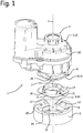
- Fig. 1 shows a fastening construction 1, in particular for an exterior vision unit of a motor vehicle.
- the construction and operation of an exterior vision unit are known to those skilled in the art, and will not be further elucidated here.
- For details regarding the construction and operation of an exterior vision unit reference is made to NL1019258 in which an exterior vision unit is described, and the contents of which may be considered inserted herein by reference.
- a first embodiment of the fastening construction 1 comprises a base part 3 which can be fixedly connected with a vehicle, and a rotation part 4 which is couplable with the base part 3.
- the rotation part 4 in coupled condition forms a central shaft 5 for pivotally bearing-mounting a housing 20 of an exterior vision unit, not represented.
- the base part 3 and the rotation part 4 are provided with at least one cam and groove pair 7, 8 cooperating as a bayonet catch 6.
- the rotation part 4 is provided with a main shaft part 10 extending along the geometric axis 2 and a bearing part 11 extending substantially radially with respect to the geometric axis 2 for bearing in a chamber 12 in the base part 3.
- the bearing part 11 together with the chamber 12 embody the bayonet catch 6.
- the cam 7 in this example is implemented as a radially protruding corner point of the bearing part 11, here of plate-shaped design, and the groove 8 is formed under a projection 14 on the wall 13 of the chamber 12, between the lower edge of the projection 14 and the bottom 15 of the chamber 12.
- the bearing part 11 fits into the chamber 12 in the base part 3, which chamber 12 is provided with an access opening 16 corresponding to the bearing part 11.
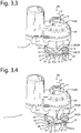
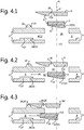
- the rotation part 4 in a first angular position ⁇ 1 of the rotation part 4 relative to the base part 3, can be displaced in the direction of the arrow P1 along a geometric axis 2 to the base part 3 to align the cam and groove pair 7, 8 for cooperation.
- the rotation part 4 is pivotable about the geometric axis 2 in the direction of arrow P2 from the first angular position ⁇ 1 to a second angular position ⁇ 2.
- the second angular position ⁇ 2 is shown in Figs. 3.5 and 4.5 . In the second angular position the cam 7 of the bayonet catch 6 extends into the groove 8, so that axial movement in a direction opposite to the arrow P1 is counteracted.
- the cam and groove pair 7, 8 cooperate via a forcible filling element 17.
- the forcible filling element 17 in this example is implemented as a filling plate from plastics material which is relatively easily spreadable with respect to the metal of the cam and groove pair 7, 8.
- the forcible filling element 17 forms a separate component which is carried on an underside of the bearing part 11 of the rotation part 4.
- the forcible filling element 17 is provided with fastening elements 18.
- the forcible filling element 17 in this embodiment is provided with a centering, preferably a self-centering, cylindrical bearing part 19.
- the self-centering bearing part 19 is furthermore provided with guide elements 19a in the form of axially extending cams.
- the cams extend free from play to a ring-shaped inner wall of the base part 3, and lock the cylindrical bearing part 19 by elastic and/or plastic deformation of the cams in radial direction, free from play.
- the guide elements 19a in the form of axially extending cams may extend inwards, for example for cooperation with a ring-shaped outer wall of the base part 3.
- the forcible filling element 17 is furthermore provided with cams 21 having wedge-fashion rising contact surfaces 22, which cooperate with corresponding contact surfaces 23 of forcing elements 27 on the bottom 15 of the base part 3.
- FIG. 3.6 and 4.6 there is shown that the rotation part 4 moves under forced displacement of material of the filling element 17 from the second angular position ⁇ 2 in the direction of arrow P3 about the geometric axis 2 to the third angular position ⁇ 3, in which the rotation part 4 is locked relative to the base part 3 axially along the geometric axis 2. Movement in the direction of arrow P1 is now hindered as well, so that the cam and groove pair 7, 8 of the bayonet catch 6 are axially fixed. The axial space between cam and groove pair 7, 8 of the bayonet catch 6 is then filled up with material of a first section of the filling element 17, in particular the filling plate and a part of the cams 21.
- Material of a second section of the filling element 17 which is surplus in the axial space, in particular the tops of the cams 21, is displaced upon tightening from the second angular position ⁇ 2 in the direction of arrow P3 to the third angular position ⁇ 3 by forcing.
- the rotation part 4 furthermore comprises a flange 9 implemented as a separate component.
- the flange 9 is rotation-coupled with the central shaft 5, but is axially slidable along the geometric axis 2.
- the flange 9 is biased under spring action towards the bearing part 11.
- a helical spring - not shown - arranged around the central shaft 5, which is restrained by the central shaft 5 and which presses on the flange 9.
- the helical spring is under a bias.
- the rotation part 4 and the base part 3 are furthermore provided with cooperating blocking parts 24 which restrain the rotation part 4 in the third angular position ⁇ 3 from rotation about the geometric axis 2 relative to the base part 3.
- the blocking parts 24 are implemented as cams 25 on the base part 3 which cooperate with corresponding recesses 26 in the flange 9.
- the coupling cam 25 of the cooperating blocking parts 24 in the third angular position ⁇ 3 is received in the recess 26 in a rotation-locking manner, and the rotation part 4 in the third angular position ⁇ 3 is blocked from rotation about the geometric axis 2 relative to the base part 3. This allows a moment to be exerted on the rotation part 4 without the locking action of the bayonet catch 6 being influenced, and can prevent the bayonet catch 6 becoming undone unintendedly.
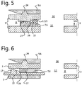
- Fig. 5 analogously to Fig. 4.6 , a variant on the first embodiment is shown where the forcible intermediate element 17 is borne on the cam 7 of the bayonet catch 6, and the forcing element 27 extends downwards from an upper side of the groove 8.
- Fig. 6 a further variant on the first embodiment is shown where the forcible intermediate element 17 forms a separate component which is received rotation-locked with the base part 3 in the chamber 12 between the cam 7 and groove 8.
- a second embodiment of a fastening construction 1 is shown.
- the forcible intermediate element 17 is received as a ring in a rotation-locked manner in the bottom 15 of the chamber 12 of the base part 3.
- the cams 21 are provided with convex contact surfaces 22, which cooperate with edges 28 of the cams 7 as forcing elements 27.
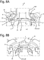
- Figs. 8a and 8b there is shown a comparable third embodiment of a fastening construction 1, where the forcible element 17 is implemented as a central ring with cams 21 set up in a cross, extending radially outwards and having convex contact surfaces 22 which cooperate with edges 28 of the cams 7 of the rotation part 4 of the bayonet catch 6.
- the fastening construction may be provided with a driving mechanism to adjust the housing electrically and the cam and groove pair of the bayonet catch may be implemented in a variety of ways.
Landscapes
- Engineering & Computer Science (AREA)
- Multimedia (AREA)
- Mechanical Engineering (AREA)
- Snaps, Bayonet Connections, Set Pins, And Snap Rings (AREA)
- Rear-View Mirror Devices That Are Mounted On The Exterior Of The Vehicle (AREA)
- Clamps And Clips (AREA)
Description
- The invention relates to a fastening construction, in particular for an exterior vision unit of a motor vehicle, comprising a base part which can be fixedly connected with a vehicle, and a rotation part which is couplable with the base part and which in coupled condition forms a central shaft for pivotally bearing-mounting a housing of an exterior vision unit.
- Such a fastening construction is known from
NL1019258 - It is customary to design exterior vision units of motor vehicles in such a manner that they can pivot towards the vehicle, for instance in case of a calamity, such as a collision, or to occupy less space in parked condition. The exterior vision units are then designed with a central shaft, which is fixedly connected with the vehicle and around which the housing of the exterior vision unit with the frame, exterior mirror and other provisions can rotate after a particular moment is exceeded.
- Because exterior vision units are mostly assembled separately and are mounted to the car as an assembly, the central shaft is often designed as a part of the rotation part which can be coupled to a fixed part of the car, the base part.
- This coupling can be carried out by connecting the rotation part by the central shaft with the base part using screws. The central shaft is then provided, for instance, with one or more holes which correspond with threaded holes in the base part. This solution has as an advantage that an operationally reliable connection can be made, but as a disadvantage that a large number of additional assembly operations are required, and that, moreover, per threaded hole an additional part is required: the screw.
- It has been found that fitting the screws can lead to errors. In particular, it may be forgotten to fit screws and/or loose screws may remain behind in the exterior vision unit. In addition, the tightening force of screws is difficult to control. Also, the screws require additional mounting space, which may seriously hamper the freedom in the design of the exterior vision unit.
- In
NL1019258 - While this construction offers many advantages, it has been found difficult in practice to realize the axial lock in an operationally reliable manner free from play. In particular, it is relatively costly to manufacture the cam and groove pairs with low axial play and, also, axial play can increase in the course of the construction's life due to external factors such as vibrations and temperature fluctuations.
- To counteract these disadvantages it has been proposed in
NL2015897 claim 1, to provide the bayonet catch with a cam and groove pair cooperating under wedging action in combination with a breakable coupling. By providing the bayonet catch with a cam and groove pair cooperating under wedging action, it is made possible, through the wedging effect upon rotation to the second position, to eliminate the axial play from the bayonet catch, and even to apply an axial bias. The rotation part can furthermore comprise a flange implemented as a separate part which is breakably rotation-coupled with the central shaft. By providing a breakable coupling between flange and rotation part, it can be ensured at the same time that, even at a relatively wide axial tolerance between cam and groove pair, during tightening a predetermined maximum tightening moment on the bayonet catch is not exceeded. Thus, with the fastening construction an axially low-play or even no-play lock-up can be realized cost-effectively and reliably. A disadvantage of this solution, however, is that this construction is relatively complex to implement in practice. - The invention contemplates an ameliorated fastening construction, especially one that is simpler to implement. In particular, the invention contemplates a fastening construction with a cam and groove pair cooperating as a bayonet catch, with which, whilst preserving the advantages mentioned, the disadvantages mentioned can be counteracted.
- To that end, the invention provides an exterior vision unit fastening construction for a motor vehicle, comprising a base part which can be fixedly connected with a vehicle, and a rotation part which is couplable with the base part and which in coupled condition forms a central shaft for pivotally bearing-mounting a housing of an exterior vision unit, wherein the base part and the rotation part are provided with at least one cam and groove pair cooperating as a bayonet catch, such that in a first angular position of the rotation part with respect to the base part, the rotation part for the purpose of coupling can be displaced along a geometric axis to the base part to align the cam and groove pair for cooperation and the rotation part is pivotable about the geometric axis from the first angular position to a second angular position in which the cam and groove pair cooperate via a forcible filling element, so that the rotation part can rotate under forced displacement of material of the filling element from the second angular position about the geometric axis to a third angular position, and the rotation part is locked with respect to the base part axially along the geometric axis.
- By providing the bayonet catch with a forcible filling element, the axial play can be eliminated from the bayonet catch and even an axial bias can be applied. By use of a forcible filling element, the axial space between cam and groove pair can be filled up with material of a first section of the filling element, and material of a second section of the filling element which is surplus in the axial space can upon tightening be displaced by forcing of the material. The forced displacement of the material can involve both elastic deformation and plastic deformation of the material. When at least a part of the material of the filling element is compressed in axial direction by, for example, the cam, it can contribute by elastic deformation to an axial bias. Another part of the material can then be pushed away by the cam in tangential and/or radial direction under plastic deformation. Thus, with the fastening construction an axially low-play or even no-play lock-up can be realized cost-effectively and reliably in a relatively simple manner.
- By making the forcible filling element from a material deforming more easily with respect to the material of cam and/or groove, it can be achieved that a predetermined maximum tightening moment on the bayonet catch is not exceeded. Thus, for example, the cam and groove pair may be made from metal, while the forcible filling element is made from plastic, preferably a relatively tough and spreadable plastic, such as PA (PolyAmide) with for example a glass bead filling or filled POM (Poly-Oxy-Methacrylate). Many materials are conceivable, not unknown to those skilled in the art.
- The forcible filling element can be a separate part. As a separate part, the filling element can constitute, for example, a loose intermediate element, or, for example, it may be provided on the cam or groove, or be carried by the same. However, the forcible filling element may also be formed integrally with the cam or groove. The filling element is not a separate part then, but is part of the cam or groove.
- By providing the forcible filling element with a rising contact surface, such as a bulging or inclined contact surface, it can be ensured that even at a relatively wide axial tolerance between cam and groove pair the axial play can be removed without a high forcing power being necessary.
- When the rotation part and the base part are provided with cooperating blocking parts which block the rotation part in the third angular position from rotation about the geometric axis relative to the base part, it can be achieved that the rotation part and the base part can be locked against rotation relative to each other. As a result, during use a moment can be exerted on the rotation part without the locking action of the bayonet catch being influenced. In particular, this can prevent the bayonet catch being overloaded, or coming loose unintendedly.
- The rotation part can furthermore comprise a flange implemented as a separate part, which is rotation-coupled with the central shaft.
- When the housing of the exterior vision unit during connection cooperates with the flange in a moment-transmissive manner, in particular via a ring, arranged on the flange, with engaging elements which may be formed as cams, the exterior vision unit can be secured by rotating the housing.
- When the flange is movable relative to the rotation part axially along the geometric axis, the cooperating blocking parts can be realized in a structurally simple manner.
- When the flange during use is biased under spring action, in particular towards a bearing part extending substantially radially with respect to the geometric axis which carries a cam or groove of the bayonet catch, this allows the cooperating blocking parts to be energized in a structurally simple manner. For the purpose of generating spring action, it is then preferred to provide a spring, in particular a helical spring, arranged around the central shaft.
- Further embodiments of the fastening construction are represented in the claims.
- The invention also relates to an exterior vision unit for a motor vehicle, comprising a fastening construction.
- The invention furthermore concerns a method for fastening an exterior vision unit to a motor vehicle, wherein a rotation part of an exterior vision unit around which a housing is pivotally bearing-mounted is connected via a bayonet catch with a base part which is mounted to the motor vehicle, comprising a first assembly step in which the rotation part is displaced along a geometric axis to the base part to align at least one cam and groove pair of the bayonet catch for cooperation, and wherein in a second assembly step the rotation part, by exertion of a tightening moment, is pivoted about the geometric axis from a first angular position to a second angular position in which cam and groove pair cooperate via a forcible filling element, and wherein the rotation part is rotated, under forced displacement of material of the filling element, from the second angular position about the geometric axis to a third angular position in which the rotation part is locked with respect to the base part axially along the geometric axis. The axial space between cam and groove pair can thereby be filled up with material of a first section of the filling element, and material of a second section of the filling element which is surplus in the axial space can upon tightening be displaced by forcing of the material.
- The flange can then in the third angular position be nonrotatably coupled with the rotation part via a fixation coupling.
- Further, the rotation part in the third angular position may be blocked via cooperating blocking parts from rotation about the geometric axis relative to the base part.
- Also, the housing of the exterior vision unit may during connection cooperate moment-transmissively with the flange.
- Regarding the disclosure in this application it is noted that the technical features of the fastening construction described in the independent claim can also be regarded as an invention independently or in combination with only one or more technical features from the main claim, the subclaims or the description. Also, the method steps of the method described in the independent method claim can be regarded as an invention independently or in combination with only one or more method steps from the main claim, the subclaims or the description.
- The invention will be further elucidated on the basis of an exemplary embodiment of a fastening construction which is shown in drawings. In the drawings:
-
Fig. 1 shows a schematic perspective top plan view of a first embodiment of a fastening construction according to the invention in disassembled condition; -
Fig. 2 shows a schematic perspective bottom view of the fastening construction ofFig. 1 ; -
Figs. 3.1 through 3.6 each show a schematic perspective view of the fastening construction ofFig. 1 in successive stages during connection, and -
Figs. 4.1 through 4.6 each show a simplified side view corresponding in detail to what is shown inFigs. 3.1 through Fig. 3.6 ; -
Fig. 5 shows a variant on the first embodiment as shown inFig. 4.6 wherein the forcible intermediate element is carried on the cam, and the stop extends downwards from an upper side of the groove; -
Fig. 6 shows a further variant on the first embodiment as shown inFig. 4.6 wherein the forcible intermediate element forms a separate component which is received, rotation-locked with the groove, between cam and groove; -
Fig. 7a shows a sectioned schematic perspective bottom view of a second embodiment of a fastening construction according to the invention in mounted condition; -
Fig. 7b shows a sectioned schematic perspective top plan view of the base part of the fastening construction ofFig. 7a with the forcible intermediate element therein; -
Fig. 8a shows a sectioned schematic perspective top plan view of a third embodiment of a fastening construction according to the invention in mounted condition; -
Fig. 8b shows a sectioned schematic perspective top plan view of the base part of the fastening construction ofFig. 8a with the forcible intermediate element therein. - In the figures, the same or corresponding parts are designated by the same reference numerals. It is noted that the figures are merely shown by way of exemplary embodiment and should not be regarded as limiting in any way.
-
Fig. 1 shows afastening construction 1, in particular for an exterior vision unit of a motor vehicle. The construction and operation of an exterior vision unit are known to those skilled in the art, and will not be further elucidated here. For details regarding the construction and operation of an exterior vision unit, reference is made toNL1019258 - Referring to
Fig. 1 andFig. 2 , a first embodiment of thefastening construction 1 comprises abase part 3 which can be fixedly connected with a vehicle, and arotation part 4 which is couplable with thebase part 3. Therotation part 4 in coupled condition forms a central shaft 5 for pivotally bearing-mounting ahousing 20 of an exterior vision unit, not represented. Thebase part 3 and therotation part 4 are provided with at least one cam andgroove pair bayonet catch 6. - The
rotation part 4 is provided with a main shaft part 10 extending along thegeometric axis 2 and a bearingpart 11 extending substantially radially with respect to thegeometric axis 2 for bearing in achamber 12 in thebase part 3. In this exemplary embodiment, the bearingpart 11 together with thechamber 12 embody thebayonet catch 6. Thecam 7 in this example is implemented as a radially protruding corner point of the bearingpart 11, here of plate-shaped design, and thegroove 8 is formed under aprojection 14 on thewall 13 of thechamber 12, between the lower edge of theprojection 14 and the bottom 15 of thechamber 12. The bearingpart 11 fits into thechamber 12 in thebase part 3, whichchamber 12 is provided with an access opening 16 corresponding to the bearingpart 11. - As shown in
Figs. 3.1 and4.1 , in a first angular position α1 of therotation part 4 relative to thebase part 3, therotation part 4, for the purpose of coupling, can be displaced in the direction of the arrow P1 along ageometric axis 2 to thebase part 3 to align the cam andgroove pair groove pair Figs. 3.2 and4.2 , are aligned for cooperation, therotation part 4 is pivotable about thegeometric axis 2 in the direction of arrow P2 from the first angular position α1 to a second angular position α2. The second angular position α2 is shown inFigs. 3.5 and4.5 . In the second angular position thecam 7 of thebayonet catch 6 extends into thegroove 8, so that axial movement in a direction opposite to the arrow P1 is counteracted. - In the second angular position α2 the cam and
groove pair forcible filling element 17. Theforcible filling element 17 in this example is implemented as a filling plate from plastics material which is relatively easily spreadable with respect to the metal of the cam andgroove pair forcible filling element 17 forms a separate component which is carried on an underside of the bearingpart 11 of therotation part 4. To that end, theforcible filling element 17 is provided withfastening elements 18. Also, theforcible filling element 17 in this embodiment is provided with a centering, preferably a self-centering, cylindrical bearingpart 19. InFig. 2 , the self-centeringbearing part 19 is furthermore provided withguide elements 19a in the form of axially extending cams. The cams extend free from play to a ring-shaped inner wall of thebase part 3, and lock thecylindrical bearing part 19 by elastic and/or plastic deformation of the cams in radial direction, free from play. In alternative embodiments, theguide elements 19a in the form of axially extending cams may extend inwards, for example for cooperation with a ring-shaped outer wall of thebase part 3. Many embodiments are possible. Theforcible filling element 17 is furthermore provided withcams 21 having wedge-fashion rising contact surfaces 22, which cooperate with corresponding contact surfaces 23 of forcingelements 27 on the bottom 15 of thebase part 3. - Referring to
Figs. 3.6 and4.6 , there is shown that therotation part 4 moves under forced displacement of material of the fillingelement 17 from the second angular position α2 in the direction of arrow P3 about thegeometric axis 2 to the third angular position α3, in which therotation part 4 is locked relative to thebase part 3 axially along thegeometric axis 2. Movement in the direction of arrow P1 is now hindered as well, so that the cam andgroove pair bayonet catch 6 are axially fixed. The axial space between cam andgroove pair bayonet catch 6 is then filled up with material of a first section of the fillingelement 17, in particular the filling plate and a part of thecams 21. Material of a second section of the fillingelement 17 which is surplus in the axial space, in particular the tops of thecams 21, is displaced upon tightening from the second angular position α2 in the direction of arrow P3 to the third angular position α3 by forcing. - The
rotation part 4 furthermore comprises aflange 9 implemented as a separate component. Theflange 9 is rotation-coupled with the central shaft 5, but is axially slidable along thegeometric axis 2. During use, theflange 9 is biased under spring action towards the bearingpart 11. For generating spring action, there is provided a helical spring - not shown - arranged around the central shaft 5, which is restrained by the central shaft 5 and which presses on theflange 9. In a preferred embodiment the helical spring is under a bias. When, for the purpose of coupling, therotation part 4, as shown inFigs. 3.1 and4.1 , is moved in the direction of the arrow P1 along thegeometric axis 2 towards thebase part 3 to align the cam andgroove pair flange 9 is restrained by thebase part 3, while the main shaft part 10 and the bearingpart 11 move on axially. The spring is thereby compressed and when the cam andgroove pair Figures 3.2 and4.2 are aligned for cooperation, the driving part is under a strong spring action. - The
rotation part 4 and thebase part 3 are furthermore provided with cooperating blockingparts 24 which restrain therotation part 4 in the third angular position α3 from rotation about thegeometric axis 2 relative to thebase part 3. The blockingparts 24 are implemented ascams 25 on thebase part 3 which cooperate withcorresponding recesses 26 in theflange 9. Referring toFigs. 3.3 - 3.6 andFigs. 4.3 - 4.6 , there is shown that theflange 9 when rotating in the direction of the arrows P2 and P3, upon passing the second angular position is lifted up by thecam 25 against the action of the spring in a direction opposite to the direction of arrow P1, and thereupon, in the third angular position α3 under spring action moves in the direction of arrow P1 downward again in that thecam 25 is received inrecess 26. Thus, therotation part 4 in the third angular position α3 is locked against rotation relative to thebase part 3. Thus, thecoupling cam 25 of the cooperating blockingparts 24 in the third angular position α3 is received in therecess 26 in a rotation-locking manner, and therotation part 4 in the third angular position α3 is blocked from rotation about thegeometric axis 2 relative to thebase part 3. This allows a moment to be exerted on therotation part 4 without the locking action of thebayonet catch 6 being influenced, and can prevent thebayonet catch 6 becoming undone unintendedly. - In
Fig. 5 , analogously toFig. 4.6 , a variant on the first embodiment is shown where the forcibleintermediate element 17 is borne on thecam 7 of thebayonet catch 6, and the forcingelement 27 extends downwards from an upper side of thegroove 8. - In
Fig. 6 a further variant on the first embodiment is shown where the forcibleintermediate element 17 forms a separate component which is received rotation-locked with thebase part 3 in thechamber 12 between thecam 7 andgroove 8. - In
Fig. 7a and Fig. 7b a second embodiment of afastening construction 1 according to the invention is shown. Here, the forcibleintermediate element 17 is received as a ring in a rotation-locked manner in the bottom 15 of thechamber 12 of thebase part 3. In this embodiment, thecams 21 are provided with convex contact surfaces 22, which cooperate withedges 28 of thecams 7 as forcingelements 27. - In
Figs. 8a and 8b , there is shown a comparable third embodiment of afastening construction 1, where theforcible element 17 is implemented as a central ring withcams 21 set up in a cross, extending radially outwards and having convex contact surfaces 22 which cooperate withedges 28 of thecams 7 of therotation part 4 of thebayonet catch 6. - The invention is not limited to the exemplary embodiments represented here. In particular, the fastening construction may be provided with a driving mechanism to adjust the housing electrically and the cam and groove pair of the bayonet catch may be implemented in a variety of ways.
- These and other variations will be clear to one skilled in the art and are understood to be within the scope of the invention as represented in the following claims.
-
- 1.
- fastening construction
- 2.
- geometric axis
- 3.
- base part
- 4.
- rotation part
- 5.
- central shaft
- 6.
- bayonet catch
- 7.
- cam
- 8.
- groove
- 9.
- flange
- 10.
- main shaft part
- 11.
- bearing part
- 12.
- chamber
- 13.
- wall
- 14.
- projection
- 15.
- bottom
- 16.
- access opening
- 17.
- forcible filling element
- 18.
- fastening element
- 19.
- bearing part
- 19a.
- guide element
- 20.
- housing
- 21.
- cam
- 22.
- contact surface
- 23.
- contact surface
- 24.
- blocking part
- 25.
- cam
- 26.
- recess
- 27.
- forcing element
- 28.
- edge
- P1
- Arrow
- P2
- Arrow
- P3
- Arrow
- α1
- first angular position
- α2
- second angular position
- α3
- third angular position
Claims (21)
- An exterior vision unit fastening construction (1) for a motor vehicle, comprising a base part (3) which can be fixedly connected with a vehicle, and a rotation part (4) which is couplable with the base part (3) and which in coupled condition forms a central shaft (5) for pivotally bearing-mounting a housing (20) of an exterior vision unit, wherein the base part (3) and the rotation part (4) are provided with at least one cam and groove pair (7,8) cooperating as a bayonet catch (6), such that in a first angular position (α1) of the rotation part (4) with respect to the base part (3), the rotation part (4) for the purpose of coupling can be displaced along a geometric axis (2) to the base part (3) to align the cam and groove pair for cooperation and the rotation part (4) is pivotable about the geometric axis (2) from the first angular position (α1) to a second angular position (α2) in which the cam and groove pair (7,8) cooperate, characterised in that the cam and groove pair (7,8) cooperate via a forcible filling element (17), so that the rotation part (4) can rotate under forced displacement of material of the filling element from the second angular position (α2) about the geometric axis (2) to a third angular position (α3), and the rotation part (4) is locked with respect to the base part (3) axially along the geometric axis (2).
- The fastening construction (1) according to claim 1, wherein the forcible filling element (17) is made from plastic, preferably a relatively tough and spreadable plastic.
- The fastening construction (1) according to claim 1 or 2, wherein the forcible filling element (17) is a separate part.
- The fastening construction (1) according to any one of the preceding claims, wherein the forcible filling element (17) is provided with at least one guide element (19a) for centering the rotation part (4) around the geometric axis (2) with respect to the base part (3).
- The fastening construction (1) according to any one of the preceding claims, wherein the forcible filling element (17) is arranged on the cam or groove, or is carried thereby.
- The fastening construction (1) according to any one of the preceding claims, wherein the forcible filling element (17) is provided with a rising contact surface, in particular a bulging or inclined contact surface.
- The fastening construction (1) according to any one of the preceding claims, wherein the rotation part (4) and the base part (3) are provided with cooperating blocking parts (24) which block the rotation part (4) in the third angular position (α3) against rotation about the geometric axis (2) relative to the base part (3).
- The fastening construction (1) according to any one of the preceding claims, wherein the rotation part (4) furthermore comprises a flange implemented as a separate part which is rotation-coupled with the central shaft (5).
- The fastening construction (1) according to claim 8, wherein the housing (20) of the exterior vision unit during connection cooperates with the flange in a moment-transmissive manner, in particular via a ring, arranged on the flange, with engaging elements, which may be formed as cams.
- The fastening construction (1) according to claim 8 or 9, wherein the flange is movable relative to the rotation part (4) axially along the geometric axis (2).
- The fastening construction (1) according to any one of claims 8-10, wherein the flange during use is biased under spring action, in particular towards a bearing part (11) extending substantially radially with respect to the geometric axis (2), which carries a cam or groove of the bayonet catch (6).
- The fastening construction (1) according to any one of the preceding claims, wherein the rotation part (4) is provided with a main shaft part (10) extending along the geometric axis (2) and a bearing part (11) extending substantially radially with respect to the geometric axis (2) for bearing in a chamber (12) in the base part (3), wherein the bearing part (11) together with the chamber (12) forms the bayonet catch (6).
- The fastening construction (1) according to any one of the preceding claims, wherein for the purpose of generating spring action, there is provided a spring, in particular a helical spring, arranged around the central shaft (5).
- The fastening construction (1) according to any one of the preceding claims, wherein the cooperating blocking parts (24) comprise a recess in the base part (3) in which the coupling cam in the third angular position (α3) is received in a rotation-locking manner.
- The fastening construction (1) according to any one of the preceding claims, provided with a housing (20), bearing-mounted around the rotation part (4), for an exterior vision unit.
- An exterior vision unit for a motor vehicle, comprising a fastening construction (1) according to any one of the preceding claims.
- A method for fastening an exterior vision unit to a motor vehicle, wherein a rotation part (4) of an exterior vision unit around which a housing (20) is pivotally bearing-mounted is connected via a bayonet catch (6) with a base part (3) which is mounted to the motor vehicle, comprising a first assembly step in which the rotation part (4) is displaced along a geometric axis (2) to the base part (3) to align at least one cam and groove pair of the bayonet catch (6) for cooperation, and wherein in a second assembly step the rotation part (4), by exertion of a tightening moment around the geometric axis (2), is pivoted from a first angular position (α1) to a second angular position (α2) characterised by, the cam and groove pair cooperate via a forcible filling element (17), and wherein the rotation part (4) is rotated under forced displacement of material of the filling element from the second angular position (α2) around the geometric axis (2) to a third angular position (α3) in which the rotation part (4) is locked with respect to the base part (3) axially along the geometric axis (2).
- The method according to claim 17, wherein the axial space between cam and groove pair is filled up with material of a first section of the filling element, and material of a second section of the filling element which is surplus in the axial space is displaced upon tightening by forcing of the material.
- The method according to claim 17 or 18, wherein the flange in the third angular position (α3) is nonrotatably coupled with the rotation part (4) via a fixation coupling.
- The method according to any one of claims 17-19, wherein the rotation part (4) in the third angular position (α3) is blocked via cooperating blocking parts (24) from rotation about the geometrical axis relative to the base part (3).
- The method according to any one of claims 17-20, wherein the housing (20) of the exterior vision unit during connection cooperates with the flange in a moment-transmissive manner.
Applications Claiming Priority (2)
| Application Number | Priority Date | Filing Date | Title |
|---|---|---|---|
| NL2019778A NL2019778B1 (en) | 2017-10-20 | 2017-10-20 | Fixing structure, in particular for an outside view unit of a motor vehicle |
| PCT/NL2018/050692 WO2019078724A1 (en) | 2017-10-20 | 2018-10-22 | Fastening construction, in particular for an exterior vision unit of a motor vehicle |
Publications (2)
| Publication Number | Publication Date |
|---|---|
| EP3697645A1 EP3697645A1 (en) | 2020-08-26 |
| EP3697645B1 true EP3697645B1 (en) | 2021-07-07 |
Family
ID=60766105
Family Applications (1)
| Application Number | Title | Priority Date | Filing Date |
|---|---|---|---|
| EP18812362.4A Active EP3697645B1 (en) | 2017-10-20 | 2018-10-22 | Fastening construction, in particular for an exterior vision unit of a motor vehicle |
Country Status (7)
| Country | Link |
|---|---|
| US (1) | US11273765B2 (en) |
| EP (1) | EP3697645B1 (en) |
| JP (1) | JP7250010B2 (en) |
| KR (1) | KR102378009B1 (en) |
| CN (1) | CN111263711B (en) |
| NL (1) | NL2019778B1 (en) |
| WO (1) | WO2019078724A1 (en) |
Families Citing this family (5)
| Publication number | Priority date | Publication date | Assignee | Title |
|---|---|---|---|---|
| NL2023881B1 (en) * | 2019-09-23 | 2021-05-25 | Mci Mirror Controls Int Netherlands B V | Drive component for an adjustment tool |
| NL2025061B1 (en) * | 2020-03-05 | 2021-10-14 | Mci Mirror Controls Int Netherlands B V | Adjustment device, and method for assembling |
| NL2026693B1 (en) * | 2020-10-16 | 2022-06-14 | Mci Mirror Controls Int Netherlands B V | Adjusting instrument comprising mutually cooperating cam patterns, in particular for adjusting an exterior vision unit of a vehicle |
| KR102500757B1 (en) * | 2021-04-14 | 2023-02-17 | 주식회사 에스엠알오토모티브모듈코리아 | An actuator for an outside rearview mirror for a vehicle |
| US20250161628A1 (en) * | 2022-02-15 | 2025-05-22 | Biotronik Ag | Packaging arrangement for a medical device and connecting element for such a packaging arrangement |
Family Cites Families (27)
| Publication number | Priority date | Publication date | Assignee | Title |
|---|---|---|---|---|
| JPS49133582U (en) * | 1973-03-19 | 1974-11-16 | ||
| JPH0517819U (en) * | 1991-08-16 | 1993-03-05 | スタンレー電気株式会社 | Bulb socket fitting structure for vehicle lighting |
| AUPM942394A0 (en) * | 1994-11-14 | 1994-12-08 | Britax Rainsfords Pty Ltd | A detent mechanism |
| NL1003144C2 (en) * | 1996-05-15 | 1997-11-18 | Iku Holding Montfoort Bv | Electrically operated hinge actuator, and outside mirror with electrically operated hinge mechanism. |
| AUPP853699A0 (en) * | 1999-02-05 | 1999-03-04 | Britax Rainsfords Pty Ltd | A pivot with a detent |
| DE10051126A1 (en) * | 1999-11-27 | 2001-05-31 | Continental Teves Ag & Co Ohg | Hydraulic block, esp. valve block for motor vehicle brake system has component fastened to it in individual connection points by caulking or clinching |
| DE10009579B4 (en) * | 2000-02-29 | 2006-02-23 | Bühler Motor GmbH | Exterior rearview mirror for a motor vehicle |
| NL1018687C2 (en) * | 2001-08-02 | 2003-02-04 | Iku Holding Montfoort Bv | Hinge construction and hinge actuator, in particular for an exterior mirror of a motor vehicle. |
| NL1019258C2 (en) * | 2001-10-30 | 2003-05-02 | Iku Holding Montfoort Bv | Fastening construction, in particular for an exterior mirror of a motor vehicle. |
| NL1025437C2 (en) * | 2004-02-06 | 2005-08-09 | Iku Holding Montfoort Bv | Hinge actuator. |
| WO2005075249A1 (en) * | 2004-02-06 | 2005-08-18 | Eaton Automotive B.V. | Hinge actuator and method for adjusting two parts of a hinge actuator relative to each other |
| BRPI0706807B1 (en) * | 2006-01-24 | 2018-03-13 | Fico Mirrors Sa | EXTERNAL REAR MIRROR FOR MOTOR VEHICLES |
| NL1031808C2 (en) * | 2006-05-12 | 2007-11-15 | Eaton Automotive Bv | Hinge construction. |
| NL1032368C2 (en) * | 2006-08-25 | 2008-02-26 | Eaton Automotive Bv | Hinge construction as well as exterior mirror unit, in particular for a motor vehicle. |
| JP4985276B2 (en) * | 2007-09-27 | 2012-07-25 | 市光工業株式会社 | Outside mirror device for vehicle |
| KR100963386B1 (en) * | 2008-12-18 | 2010-06-14 | 에스엠알 페턴츠 에스.에이.알.엘. | Driver for outside view mirror for vehicle |
| JP5501746B2 (en) * | 2009-12-11 | 2014-05-28 | 株式会社村上開明堂 | Door mirror and its assembly method |
| NL2006301C2 (en) * | 2010-10-06 | 2012-04-11 | Mci Mirror Controls Int Nl Bv | ADJUSTMENT MECHANISM. |
| EP2439106B1 (en) * | 2010-10-08 | 2012-12-05 | SMR Patents S.à.r.l. | Power fold mechanism |
| DE202012003399U1 (en) * | 2012-02-16 | 2012-04-19 | Mci (Mirror Controls International) Netherlands B.V. | Exterior mirror and hinge actuator for such |
| EP2639112B1 (en) * | 2012-03-14 | 2014-10-01 | Magna Auteca AG | Group of external mirrors with different functions |
| JP5961025B2 (en) * | 2012-04-12 | 2016-08-02 | 株式会社小糸製作所 | Light source mounting structure for vehicle lamp |
| NL2012333B1 (en) * | 2014-02-28 | 2015-10-19 | MCI (Mirror Controls International) Netherlands B V | Mirror adjustment mechanism, in particular for a wing mirror for a motor vehicle. |
| NL2014026B1 (en) * | 2014-12-19 | 2016-10-12 | MCI (Mirror Controls International) Netherlands B V | Mounting construction, exterior mirror part, body part, exterior mirror unit, motor vehicle and working method. |
| NL2015676B1 (en) * | 2015-10-28 | 2017-05-29 | MCI (Mirror Controls International) Netherlands B V | Adjustment instrument for an outside view unit for a vehicle. |
| NL2015897B1 (en) * | 2015-12-02 | 2017-06-28 | MCI (Mirror Controls International) Netherlands B V | Fixing structure, in particular for an outside view unit of a motor vehicle. |
| NL2020820B1 (en) * | 2018-04-24 | 2019-10-31 | Mci Mirror Controls Int Netherlands B V | Adjustment instrument, in particular for adjusting an outside view unit of a vehicle |
-
2017
- 2017-10-20 NL NL2019778A patent/NL2019778B1/en not_active IP Right Cessation
-
2018
- 2018-10-22 WO PCT/NL2018/050692 patent/WO2019078724A1/en not_active Ceased
- 2018-10-22 KR KR1020207014259A patent/KR102378009B1/en active Active
- 2018-10-22 EP EP18812362.4A patent/EP3697645B1/en active Active
- 2018-10-22 US US16/757,004 patent/US11273765B2/en active Active
- 2018-10-22 JP JP2020522015A patent/JP7250010B2/en active Active
- 2018-10-22 CN CN201880065973.XA patent/CN111263711B/en active Active
Also Published As
| Publication number | Publication date |
|---|---|
| JP2021500262A (en) | 2021-01-07 |
| NL2019778B1 (en) | 2019-04-29 |
| WO2019078724A1 (en) | 2019-04-25 |
| US20200339037A1 (en) | 2020-10-29 |
| US11273765B2 (en) | 2022-03-15 |
| KR20200088814A (en) | 2020-07-23 |
| CN111263711A (en) | 2020-06-09 |
| EP3697645A1 (en) | 2020-08-26 |
| KR102378009B1 (en) | 2022-03-23 |
| CN111263711B (en) | 2023-10-13 |
| JP7250010B2 (en) | 2023-03-31 |
Similar Documents
| Publication | Publication Date | Title |
|---|---|---|
| US11273765B2 (en) | Fastening construction, in particular for an exterior vision unit of a motor vehicle | |
| EP3383705B1 (en) | Fastening construction, in particular for an exterior vision unit of a motor vehicle | |
| US6742756B1 (en) | Pivot with a detent | |
| US20170233063A1 (en) | Lock mechanism, propeller having a lock mechanism, and aerial vehicle | |
| EP3093211B1 (en) | Steering device | |
| KR20040038986A (en) | System with a tool holding fixture | |
| KR101589859B1 (en) | Assembly comprising a component and a fastening system for flexible connection of the component on a plate-shaped support member | |
| US5310276A (en) | Connection device between two mechanical components | |
| CN101561006A (en) | Connection component for attaching an extension element to a carrier element | |
| WO2018215599A1 (en) | Pivot joint system and rear view device therewith | |
| US9915340B2 (en) | Housing for a steering gear | |
| WO2015160500A1 (en) | Clip for fastening a panel on a support, method for implementing same, and motor vehicle equipment | |
| WO2018153548A1 (en) | Drive, comprising an electric motor and a transmission, and method for producing a drive | |
| EP3788702B1 (en) | Electric motor with a coupling between the rotor shaft and the shaft of an angle sensor | |
| GB2343495A (en) | Spring strut mounting | |
| US20180180155A1 (en) | Drive wheel for a transmission drive device, and transmission drive device | |
| US20200325720A1 (en) | Spindle drive for an adjusting element of a motor vehicle | |
| WO2020052680A1 (en) | Antenna module for motor vehicle | |
| CN105751854A (en) | Venting Device | |
| EP1683250B1 (en) | Electric motor with self-adjusting bushing structure | |
| CN106402353B (en) | Transmission housing and transmission drive unit | |
| KR102066947B1 (en) | clinching nut for self tapping | |
| WO2018153550A1 (en) | Drive, comprising an electric motor and a transmission, and method for producing a drive | |
| KR20160043982A (en) | Ratcheting freewheel | |
| EP3141429B1 (en) | Vehicular door mirror |
Legal Events
| Date | Code | Title | Description |
|---|---|---|---|
| STAA | Information on the status of an ep patent application or granted ep patent |
Free format text: STATUS: UNKNOWN |
|
| STAA | Information on the status of an ep patent application or granted ep patent |
Free format text: STATUS: THE INTERNATIONAL PUBLICATION HAS BEEN MADE |
|
| PUAI | Public reference made under article 153(3) epc to a published international application that has entered the european phase |
Free format text: ORIGINAL CODE: 0009012 |
|
| STAA | Information on the status of an ep patent application or granted ep patent |
Free format text: STATUS: REQUEST FOR EXAMINATION WAS MADE |
|
| 17P | Request for examination filed |
Effective date: 20200429 |
|
| AK | Designated contracting states |
Kind code of ref document: A1 Designated state(s): AL AT BE BG CH CY CZ DE DK EE ES FI FR GB GR HR HU IE IS IT LI LT LU LV MC MK MT NL NO PL PT RO RS SE SI SK SM TR |
|
| AX | Request for extension of the european patent |
Extension state: BA ME |
|
| DAV | Request for validation of the european patent (deleted) | ||
| DAX | Request for extension of the european patent (deleted) | ||
| GRAP | Despatch of communication of intention to grant a patent |
Free format text: ORIGINAL CODE: EPIDOSNIGR1 |
|
| STAA | Information on the status of an ep patent application or granted ep patent |
Free format text: STATUS: GRANT OF PATENT IS INTENDED |
|
| INTG | Intention to grant announced |
Effective date: 20210301 |
|
| GRAS | Grant fee paid |
Free format text: ORIGINAL CODE: EPIDOSNIGR3 |
|
| GRAA | (expected) grant |
Free format text: ORIGINAL CODE: 0009210 |
|
| STAA | Information on the status of an ep patent application or granted ep patent |
Free format text: STATUS: THE PATENT HAS BEEN GRANTED |
|
| AK | Designated contracting states |
Kind code of ref document: B1 Designated state(s): AL AT BE BG CH CY CZ DE DK EE ES FI FR GB GR HR HU IE IS IT LI LT LU LV MC MK MT NL NO PL PT RO RS SE SI SK SM TR |
|
| REG | Reference to a national code |
Ref country code: GB Ref legal event code: FG4D |
|
| REG | Reference to a national code |
Ref country code: AT Ref legal event code: REF Ref document number: 1408262 Country of ref document: AT Kind code of ref document: T Effective date: 20210715 |
|
| REG | Reference to a national code |
Ref country code: DE Ref legal event code: R096 Ref document number: 602018019882 Country of ref document: DE |
|
| REG | Reference to a national code |
Ref country code: IE Ref legal event code: FG4D |
|
| REG | Reference to a national code |
Ref country code: LT Ref legal event code: MG9D |
|
| REG | Reference to a national code |
Ref country code: NL Ref legal event code: MP Effective date: 20210707 |
|
| REG | Reference to a national code |
Ref country code: AT Ref legal event code: MK05 Ref document number: 1408262 Country of ref document: AT Kind code of ref document: T Effective date: 20210707 |
|
| PG25 | Lapsed in a contracting state [announced via postgrant information from national office to epo] |
Ref country code: LT Free format text: LAPSE BECAUSE OF FAILURE TO SUBMIT A TRANSLATION OF THE DESCRIPTION OR TO PAY THE FEE WITHIN THE PRESCRIBED TIME-LIMIT Effective date: 20210707 Ref country code: AT Free format text: LAPSE BECAUSE OF FAILURE TO SUBMIT A TRANSLATION OF THE DESCRIPTION OR TO PAY THE FEE WITHIN THE PRESCRIBED TIME-LIMIT Effective date: 20210707 Ref country code: BG Free format text: LAPSE BECAUSE OF FAILURE TO SUBMIT A TRANSLATION OF THE DESCRIPTION OR TO PAY THE FEE WITHIN THE PRESCRIBED TIME-LIMIT Effective date: 20211007 Ref country code: HR Free format text: LAPSE BECAUSE OF FAILURE TO SUBMIT A TRANSLATION OF THE DESCRIPTION OR TO PAY THE FEE WITHIN THE PRESCRIBED TIME-LIMIT Effective date: 20210707 Ref country code: NO Free format text: LAPSE BECAUSE OF FAILURE TO SUBMIT A TRANSLATION OF THE DESCRIPTION OR TO PAY THE FEE WITHIN THE PRESCRIBED TIME-LIMIT Effective date: 20211007 Ref country code: NL Free format text: LAPSE BECAUSE OF FAILURE TO SUBMIT A TRANSLATION OF THE DESCRIPTION OR TO PAY THE FEE WITHIN THE PRESCRIBED TIME-LIMIT Effective date: 20210707 Ref country code: PT Free format text: LAPSE BECAUSE OF FAILURE TO SUBMIT A TRANSLATION OF THE DESCRIPTION OR TO PAY THE FEE WITHIN THE PRESCRIBED TIME-LIMIT Effective date: 20211108 Ref country code: SE Free format text: LAPSE BECAUSE OF FAILURE TO SUBMIT A TRANSLATION OF THE DESCRIPTION OR TO PAY THE FEE WITHIN THE PRESCRIBED TIME-LIMIT Effective date: 20210707 Ref country code: RS Free format text: LAPSE BECAUSE OF FAILURE TO SUBMIT A TRANSLATION OF THE DESCRIPTION OR TO PAY THE FEE WITHIN THE PRESCRIBED TIME-LIMIT Effective date: 20210707 Ref country code: FI Free format text: LAPSE BECAUSE OF FAILURE TO SUBMIT A TRANSLATION OF THE DESCRIPTION OR TO PAY THE FEE WITHIN THE PRESCRIBED TIME-LIMIT Effective date: 20210707 Ref country code: ES Free format text: LAPSE BECAUSE OF FAILURE TO SUBMIT A TRANSLATION OF THE DESCRIPTION OR TO PAY THE FEE WITHIN THE PRESCRIBED TIME-LIMIT Effective date: 20210707 |
|
| PG25 | Lapsed in a contracting state [announced via postgrant information from national office to epo] |
Ref country code: PL Free format text: LAPSE BECAUSE OF FAILURE TO SUBMIT A TRANSLATION OF THE DESCRIPTION OR TO PAY THE FEE WITHIN THE PRESCRIBED TIME-LIMIT Effective date: 20210707 Ref country code: LV Free format text: LAPSE BECAUSE OF FAILURE TO SUBMIT A TRANSLATION OF THE DESCRIPTION OR TO PAY THE FEE WITHIN THE PRESCRIBED TIME-LIMIT Effective date: 20210707 Ref country code: GR Free format text: LAPSE BECAUSE OF FAILURE TO SUBMIT A TRANSLATION OF THE DESCRIPTION OR TO PAY THE FEE WITHIN THE PRESCRIBED TIME-LIMIT Effective date: 20211008 |
|
| REG | Reference to a national code |
Ref country code: DE Ref legal event code: R097 Ref document number: 602018019882 Country of ref document: DE |
|
| PG25 | Lapsed in a contracting state [announced via postgrant information from national office to epo] |
Ref country code: DK Free format text: LAPSE BECAUSE OF FAILURE TO SUBMIT A TRANSLATION OF THE DESCRIPTION OR TO PAY THE FEE WITHIN THE PRESCRIBED TIME-LIMIT Effective date: 20210707 |
|
| PLBE | No opposition filed within time limit |
Free format text: ORIGINAL CODE: 0009261 |
|
| STAA | Information on the status of an ep patent application or granted ep patent |
Free format text: STATUS: NO OPPOSITION FILED WITHIN TIME LIMIT |
|
| REG | Reference to a national code |
Ref country code: CH Ref legal event code: PL |
|
| PG25 | Lapsed in a contracting state [announced via postgrant information from national office to epo] |
Ref country code: SM Free format text: LAPSE BECAUSE OF FAILURE TO SUBMIT A TRANSLATION OF THE DESCRIPTION OR TO PAY THE FEE WITHIN THE PRESCRIBED TIME-LIMIT Effective date: 20210707 Ref country code: SK Free format text: LAPSE BECAUSE OF FAILURE TO SUBMIT A TRANSLATION OF THE DESCRIPTION OR TO PAY THE FEE WITHIN THE PRESCRIBED TIME-LIMIT Effective date: 20210707 Ref country code: RO Free format text: LAPSE BECAUSE OF FAILURE TO SUBMIT A TRANSLATION OF THE DESCRIPTION OR TO PAY THE FEE WITHIN THE PRESCRIBED TIME-LIMIT Effective date: 20210707 Ref country code: EE Free format text: LAPSE BECAUSE OF FAILURE TO SUBMIT A TRANSLATION OF THE DESCRIPTION OR TO PAY THE FEE WITHIN THE PRESCRIBED TIME-LIMIT Effective date: 20210707 Ref country code: CZ Free format text: LAPSE BECAUSE OF FAILURE TO SUBMIT A TRANSLATION OF THE DESCRIPTION OR TO PAY THE FEE WITHIN THE PRESCRIBED TIME-LIMIT Effective date: 20210707 Ref country code: AL Free format text: LAPSE BECAUSE OF FAILURE TO SUBMIT A TRANSLATION OF THE DESCRIPTION OR TO PAY THE FEE WITHIN THE PRESCRIBED TIME-LIMIT Effective date: 20210707 |
|
| 26N | No opposition filed |
Effective date: 20220408 |
|
| REG | Reference to a national code |
Ref country code: BE Ref legal event code: MM Effective date: 20211031 |
|
| PG25 | Lapsed in a contracting state [announced via postgrant information from national office to epo] |
Ref country code: MC Free format text: LAPSE BECAUSE OF FAILURE TO SUBMIT A TRANSLATION OF THE DESCRIPTION OR TO PAY THE FEE WITHIN THE PRESCRIBED TIME-LIMIT Effective date: 20210707 |
|
| PG25 | Lapsed in a contracting state [announced via postgrant information from national office to epo] |
Ref country code: LU Free format text: LAPSE BECAUSE OF NON-PAYMENT OF DUE FEES Effective date: 20211022 Ref country code: IT Free format text: LAPSE BECAUSE OF FAILURE TO SUBMIT A TRANSLATION OF THE DESCRIPTION OR TO PAY THE FEE WITHIN THE PRESCRIBED TIME-LIMIT Effective date: 20210707 Ref country code: BE Free format text: LAPSE BECAUSE OF NON-PAYMENT OF DUE FEES Effective date: 20211031 |
|
| PG25 | Lapsed in a contracting state [announced via postgrant information from national office to epo] |
Ref country code: LI Free format text: LAPSE BECAUSE OF NON-PAYMENT OF DUE FEES Effective date: 20211031 Ref country code: CH Free format text: LAPSE BECAUSE OF NON-PAYMENT OF DUE FEES Effective date: 20211031 |
|
| PG25 | Lapsed in a contracting state [announced via postgrant information from national office to epo] |
Ref country code: IE Free format text: LAPSE BECAUSE OF NON-PAYMENT OF DUE FEES Effective date: 20211022 |
|
| P01 | Opt-out of the competence of the unified patent court (upc) registered |
Effective date: 20230516 |
|
| PG25 | Lapsed in a contracting state [announced via postgrant information from national office to epo] |
Ref country code: CY Free format text: LAPSE BECAUSE OF FAILURE TO SUBMIT A TRANSLATION OF THE DESCRIPTION OR TO PAY THE FEE WITHIN THE PRESCRIBED TIME-LIMIT Effective date: 20210707 |
|
| PG25 | Lapsed in a contracting state [announced via postgrant information from national office to epo] |
Ref country code: HU Free format text: LAPSE BECAUSE OF FAILURE TO SUBMIT A TRANSLATION OF THE DESCRIPTION OR TO PAY THE FEE WITHIN THE PRESCRIBED TIME-LIMIT; INVALID AB INITIO Effective date: 20181022 |
|
| PG25 | Lapsed in a contracting state [announced via postgrant information from national office to epo] |
Ref country code: MK Free format text: LAPSE BECAUSE OF FAILURE TO SUBMIT A TRANSLATION OF THE DESCRIPTION OR TO PAY THE FEE WITHIN THE PRESCRIBED TIME-LIMIT Effective date: 20210707 |
|
| PG25 | Lapsed in a contracting state [announced via postgrant information from national office to epo] |
Ref country code: TR Free format text: LAPSE BECAUSE OF FAILURE TO SUBMIT A TRANSLATION OF THE DESCRIPTION OR TO PAY THE FEE WITHIN THE PRESCRIBED TIME-LIMIT Effective date: 20210707 |
|
| PG25 | Lapsed in a contracting state [announced via postgrant information from national office to epo] |
Ref country code: MT Free format text: LAPSE BECAUSE OF FAILURE TO SUBMIT A TRANSLATION OF THE DESCRIPTION OR TO PAY THE FEE WITHIN THE PRESCRIBED TIME-LIMIT Effective date: 20210707 |
|
| PGFP | Annual fee paid to national office [announced via postgrant information from national office to epo] |
Ref country code: DE Payment date: 20251021 Year of fee payment: 8 |
|
| PGFP | Annual fee paid to national office [announced via postgrant information from national office to epo] |
Ref country code: GB Payment date: 20251022 Year of fee payment: 8 |
|
| PGFP | Annual fee paid to national office [announced via postgrant information from national office to epo] |
Ref country code: FR Payment date: 20251030 Year of fee payment: 8 |