EP3697570B1 - Tube slitter with off-axis hinge - Google Patents
Tube slitter with off-axis hinge Download PDFInfo
- Publication number
- EP3697570B1 EP3697570B1 EP18868493.0A EP18868493A EP3697570B1 EP 3697570 B1 EP3697570 B1 EP 3697570B1 EP 18868493 A EP18868493 A EP 18868493A EP 3697570 B1 EP3697570 B1 EP 3697570B1
- Authority
- EP
- European Patent Office
- Prior art keywords
- tool
- tube
- cable
- concave surface
- portions
- Prior art date
- Legal status (The legal status is an assumption and is not a legal conclusion. Google has not performed a legal analysis and makes no representation as to the accuracy of the status listed.)
- Active
Links
Images








Classifications
-
- G—PHYSICS
- G02—OPTICS
- G02B—OPTICAL ELEMENTS, SYSTEMS OR APPARATUS
- G02B6/00—Light guides; Structural details of arrangements comprising light guides and other optical elements, e.g. couplings
- G02B6/24—Coupling light guides
- G02B6/245—Removing protective coverings of light guides before coupling
-
- B—PERFORMING OPERATIONS; TRANSPORTING
- B26—HAND CUTTING TOOLS; CUTTING; SEVERING
- B26D—CUTTING; DETAILS COMMON TO MACHINES FOR PERFORATING, PUNCHING, CUTTING-OUT, STAMPING-OUT OR SEVERING
- B26D3/00—Cutting work characterised by the nature of the cut made; Apparatus therefor
- B26D3/16—Cutting rods or tubes transversely
- B26D3/169—Hand held tube cutters
-
- B—PERFORMING OPERATIONS; TRANSPORTING
- B26—HAND CUTTING TOOLS; CUTTING; SEVERING
- B26D—CUTTING; DETAILS COMMON TO MACHINES FOR PERFORATING, PUNCHING, CUTTING-OUT, STAMPING-OUT OR SEVERING
- B26D3/00—Cutting work characterised by the nature of the cut made; Apparatus therefor
- B26D3/001—Cutting tubes longitudinally
-
- G—PHYSICS
- G02—OPTICS
- G02B—OPTICAL ELEMENTS, SYSTEMS OR APPARATUS
- G02B6/00—Light guides; Structural details of arrangements comprising light guides and other optical elements, e.g. couplings
- G02B6/46—Processes or apparatus adapted for installing or repairing optical fibres or optical cables
- G02B6/56—Processes for repairing optical cables
- G02B6/566—Devices for opening or removing the mantle
Definitions
- the present invention is directed to a tool for mid-span slitting or cutting tubes, cables or insulating jackets of cables carrying signal- or power-transmitting conduits, such as fiber optic cables.
- Fiber optic cables come in many different configurations and jacket thicknesses. In some applications, many fibers are contained in a single tube. Conventional tools used for midspan application can be difficult to use and inaccurate. Some have blade depth adjustments which can be difficult to set correctly. Other tools have a series of channels with integral blades set to specific depths. These tools rely on the opposite side blades to pierce the jacket wall. They have a clip that can be difficult to operate, and ultimately rely on the precision of the clip feature to set the depth of the cut. Other tools do not use a clip must be squeezed with continuous pressure as the tool is brought down the cable.
- Mid-span cable or tube slitter products on the market can be categorized into two groups.
- the first group is the adjustable blade slitters. This group of tools has more moving parts, fewer blades, and require the user to adjust depth of the blade corresponding to each cable size.
- the second group are fixed blade slitters. These tools have different channels sized for the outer diameter of the range of tubes. Aligned in these channels are blades with depths related to the overall wall thickness.
- the fixed blade tool category can be divided into locking tools and tools that do not lock.
- Locking tools require the end user to use a lock or latch to close the tool around the tube.
- the problem in this style of tool is that the tool will be forced open as it is being used. Since the latch will always need some amount of clearance to work properly, there is always some finite amount of loosening, as shown in Fig. 1 . This causes the overall diameter and blade setting to lose accuracy. This will result in longitudinal cuts that do not pierce the jacket fully.
- tube or cable jacket slitting or cutting tools including first and second opposite tool portions, each tool portion including a common hinged portion at a first end for engaging the opposite tool portion.
- the first and second opposite tool portions are foldable about the hinged portion between an open position and a closed, folded-together position, each of the first and second opposite tool portions having a length, width, and height, with the length extending in the direction from the hinged portion at the one end to a second end opposite the hinge.
- the width extends in the direction perpendicular to the length and the height extends in the direction perpendicular to the length and width, the first and second opposite tool portions meeting along a plane comprising the length and width when in the closed position.
- the tube or cable jacket slitting or cutting tool includes at least one concave surface extending across the width of at least one of the first and second tool portions, the at least one concave surface forming an opening, when the first and second opposite tool portions are in the closed position, through which a tube or cable may be slid with respect to the tool.
- the tube or cable jacket slitting or cutting tool includes a blade extending inward into the opening formed by the at least one concave surface for slitting or cutting a depth of the tube or cable jacket as it is moved with respect to the tool.
- the tube or cable jacket slitting or cutting tool includes a hinge pivot axis in the hinged portion extending in a direction substantially in the direction of the width and at an acute angle to either the plane or to the longitudinal axis of the tube or cable in the opening formed by the at least one concave surface.
- each of the tool portions may include an alignment portion disposed near the second end and the first tool portion alignment portion may be engagable with the second tool portion alignment portion for maintaining alignment of the tool when the tool is in the closed position.
- the tube or cable jacket slitting or cutting tool may include a projection extending from a side of first and second opposite tool portions in the direction of the tool width and wherein the at least one concave surface extends through the projection.
- the blade may extend inward into the opening formed by the at least one concave surface in the projection.
- the projection may extend between a user's fingers when the user grasps the tool with the fingers extend substantially around the closed tool portions.
- the blade may extend inward into the opening formed by the at least one concave surface in the projection.
- the at least one concave surface and blade may be removable as a unit from the at least one of the first and second tool portions.
- the tube or cable jacket slitting or cutting tool may include at least one concave surface formed into and extending across the width of each of the first and second tool portions, the at least one concave surface in each tool portion being in alignment with the other concave surface to form an opening, wherein when the first and second opposite tool portions are in the closed position, the tube or cable may be slid through the opening with respect to the tool.
- the tool may include a magnet secured in the first or second tool portion and an alloy dowel pin secured in the other of the first or second tool potion wherein the magnet is disposed adjacent the alloy dowel when the tool is in the closed position, maintaining the tool in the closed position when a tube is drawn through the tool.
- Another aspect of the present invention is directed to a method of using the tube or cable slitting tool as described above according to claim 11.
- methoda including ensuring the first and second tool portions are in an open position and placing a tube or cable having an outer jacket into the opening formed by the at least one concave surface of the first or second tool portion.
- the method includes moving the first and second tool portions to the closed position whereby the blade extending inward into at opening cuts the tube or cable outer jacket and drawing a portion of the tube or cable with respect to the tool in a parallel direction to the at least one concave surface of the first or second tool half whereby the blade produces an elongated slit in the tube or cable jacket.
- the method includes moving the tool to the open position and removing the slit tube or cable from the at least one concave surface of the first or second tool portion.
- Drawing the tube through the opening formed by the at least one concave surface in one direction may cause the first and second opposite tool portions to be urged toward one another.
- One or both of the tool portions may include a projection extending from a side thereof in the direction of the tool width, with the opening formed by the at least one concave surface extending through the projection wherein during drawing the tube through the at least one concave surface in one direction the projection extends between the tool operator's fingers when the user grasps the tool with the fingers extend substantially around the closed tool portions.
- the blade may extend inward into the opening formed by the at least one concave surface in the projection.
- a tube or cable jacket slitting or cutting tool including first and second opposite tool portions, each tool portion having a common hinged portion at a first end for engaging the opposite tool portion.
- the first and second opposite tool portions are foldable about the hinged portion between an open position and a closed, folded-together position, each of the first and second opposite tool portions having a length, width, and height.
- the length extends in the direction from the hinged portion at the one end to a second end opposite the hinge.
- the width extends in the direction perpendicular to the length, and the height extends in the direction perpendicular to the length and width.
- the first and second opposite tool portions meeting along a plane comprising the length and width when in the closed position.
- the tube or cable jacket slitting or cutting tool includes a projection extending from a side of first and second opposite tool portions in the direction of the tool width and at least one concave surface extending across the width of at least one of the first and second tool portions and through the projection.
- the at least one concave surface forms an opening, when the first and second opposite tool portions are in the closed position, through which a tube or cable may be slid with respect to the tool.
- the tube or cable jacket slitting or cutting tool includes a blade extending inward into the opening formed by the at least one concave surface in the projection for slitting or cutting a depth of the tube or cable jacket as it is moved with respect to the tool.
- the tube or cable jacket slitting or cutting tool may include a hinge pivot axis in the hinged portion extending in a direction substantially in the direction of the width and at an acute angle to either the plane or to the longitudinal axis of the tube or cable in the opening formed by the at least one concave surface.
- a method of using the tube or cable slitting tool as described includes ensuring the first and second tool portions are in an open position and placing a tube or cable having an outer jacket into the opening formed by the at least one concave surface of the first or second tool portion.
- the method includes moving the first and second tool portions to the closed position whereby the blade extending inward into at opening cuts the tube or cable outer jacket and grasping the tool with a user's fingers extend substantially around the closed tool portions wherein the projection extends between the tool operator's fingers.
- the method includes drawing a portion of the tube or cable with respect to the tool in a parallel direction to the at least one concave surface of the first or second tool half whereby the blade produces an elongated slit in the tube or cable jacket, moving the tool to the open position and removing the slit tube or cable from the at least one concave surface of the first or second tool portion.
- the tool may include a hinge pivot axis in the hinged portion extending in a direction substantially in the direction of the width and at an acute angle to either the plane or to the longitudinal axis of the tube or cable in the opening formed by the at least one concave surface wherein drawing the tube through the opening formed by the at least one concave surface with respect to the tool in one direction causes the first and second opposite tool portions to be urged toward one another.
- the tool of the present invention may be employed with a fixed blade to cut or slit a tube or cable, including cable jacket or insulation, to a desired depth set by the dimension of the blade.
- the tool of the present invention uses an angled hinge to rotate the blade(s) into the tube or cable jacket using the same motion as tool operation. This action eases the stress put on the tool operator.
- the instant tool does not need to rely on a clip to set the closed tool position, so it is more accurate than locking tools.
- FIG. 3-13 A first embodiment of the tube slitter tool of the present invention is shown in Figs. 3-13 .
- tool 20 of the present invention has first and second body halves, identified as first body portion 22a and second body portion 22b joined at one end by off-axis hinge 40.
- Body portions 22a, 22b when folded together ( Fig. 1 ) meet along a plane.
- Each body portion 22a, 22b has a length L in the direction from the hinge 40 end of the body to the end 26a, 26b opposite the hinge, and a width W perpendicular to the length.
- each body portion Molded or otherwise formed into and across the width of each body portion are one or more semi-cylindrical or otherwise concave or indented surfaces, channels or grooves 31a, 31b, 32a, 32b, 33a, 33b, 34a, 34b, 35a, 35b, 36a, 36b.
- the semi-cylindrical surfaces form cylindrical openings with longitudinal axes generally perpendicular to the body length and parallel to the body width, and that have different desired diameters to accommodate tubes or cable of different diameters within the height H of each body portion.
- the indentations, channels or grooves 31a, 31b, 32a, 32b, 33a, 33b, 34a, 34b, 35a, 35b, 36a, 36b across the body portions may be configured to the shape of the tube or cable, such as rectangular, and may be in one or the other of the body portions 22a or 22b, instead of both as shown.
- the tool cylindrical openings diameters or widths may be the same or slightly larger than the cable to be slit, to enable the cable to be slid through with respect to the tool body. Projecting into each of the openings from the semi-cylindrical surfaces on one or both body portions is a slitting or cutting blade 24.
- Blade 24 extends into semi-cylindrical surfaces 31a, 31b, 32a, 32b, 33a, 33b, 34a, 34b, 35a, 35b, 36a, 36b a distance of height sufficient to cut through the cable jacket, or otherwise make the desired cut in the tube or cable. While this blade 24 is shown as being fixed, it is possible to employ blades whose depth may be adjusted. Instead of being integrally formed into and of one piece with body portions 22a, 22b, the cable indentations, channels or grooves 31a, 31b, 32a, 32b, 33a, 33b, 34a, 34b, 35a, 35b, 36a, 36b and their associated blades 24 may be provided as a cassette removable as a unit from within body portions 22a, 22b. This would permit common body portions 22a, 22b, joined by off-axis hinge 40, to be configured for cable diameters and blade heights for different customers and applications.
- the off-axis hinge 40 is shown in more detail in Figs, 6a, 6b , 8, 9 , 11 and 13 .
- the opposite tool portions 22a, 22b are in the closed position and hinge pivot axis in hinge 40 extends in a direction substantially in the direction of the width of the tool and at an acute offset angle to both i) the plane along which the first and second opposite tool portions 22a, 22b meet and ii) the longitudinal axis of the tube or cable in the channel formed by the concave surfaces in the tool portions.
- the off-axis hinge configuration of the tool of the present invention relieves strain on the operator and ensures a consistent cut depth.
- the tool includes a face 92a on the first tool portion 22a which contacts the face 92b of the second tool portion 22b when the tool is in the closed position, the faces 92a, 92b meeting one another along a plane 100.
- the alignment features 80 comprise at least one protrusion 82 on the first tool portion 22a and at least one corresponding detent 84 on the tool second portion 22b.
- the protrusion 82 includes a top surface and tapered side walls extending from the top surface to the first tool face 92a.
- the detent 84 includes a bottom surface and tapered side walls extending from the bottom surface to the second tool face 92b.
- the protrusion 82 may be nearly engaged with the corresponding detent 84 as shown in Fig. 7a , and as the cable is drawn through in the direction of arrow 70, the force of the cable pulling the second portion 22b in the direction of arrow 70 allows the hinge 40 to force the tool portions 22a, 22b together in the direction of arrows 74, 76 because of the angle of the hinge 40 to the tool portion top surfaces 92a, 92b whereby the tool is urged to the fully closed position as shown in Fig. 7b . Additionally, the tool may be in the fully closed position before the cable is drawn in the direction of arrow 70 and the drawing movement maintains the tool in the closed position.
- the tool portions 22a, 22b may be forced away from one another directly by the user, or the cable may be drawn in the direction of arrow 72 to open the tool for removal of the cable or tube.
- These alignment features prevent excessive wear on the hinge and reduce the possibility that the tool halves will slide past each other beyond the designed closed position.
- the alignment features may include a protrusion 82 on each of the tool portions22a, 22b engagable with a detent 84 on the opposition tool portion as shown in the embodiment of Figs. 7a and 7b .
- FIG. 14-34 A second embodiment of the tube slitter tool 20' of the present invention is shown in Figs. 14-34 .
- This embodiment includes a similar off-axis hinge 40 but includes only one opening formed by concave surface indentation, channel or groove 31a, 31b across the width of the body portion configured to accept the shape of the tube or cable 50.
- the tool cylindrical opening diameter or width may be the same or slightly larger than the cable to be slit, to enable the cable to be slid through with respect to the tool body.
- a slitting or cutting blade 24 Projecting into each of the semi-cylindrical surfaces on indentation, channel or groove 31a, 31b of the body portions is a slitting or cutting blade 24, which extends a distance of height sufficient to cut through the cable jacket, or otherwise make the desired cut in the tube or cable 50.
- the body portion has extended from a side thereof a projection, consisting of body portions 122a, 122b, through which the opening formed by indentation, channel or groove 31a, 31b extends. This projection increases the width of the tool, compared to the width of body portions 22a, 22b. Blades 24 may be located in this projection, beyond the sides of the body portions 22a, 22b.
- Body portions 22a, 22b may contain on their interior slots or storage openings for spare blades and a hex wrench installation tool that are accessible when the tool is in the opened position ( Figs. 15, 17 and 20 ).
- the tube slitter tool 20' includes the first and second body portions or opposite tool portions or 22a, 22b, each tool portion including a common hinged portion at a first tool end for engaging the opposite tool portion.
- the first and second opposite tool portions 22a, 22b are foldable about the hinged portion 40 between an open position and a closed, folded-together position, each of the first and second opposite tool portions 22a, 22b having a length L, width W, and height H, with the length extending in the direction from the hinged portion at the one end to a second end opposite the hinge.
- the width W extends in the direction perpendicular to the length L and the height H extends in the direction perpendicular to the length L and width W, the first and second opposite tool portions 22a, 22b meeting along a plane 250 (highlighted line 252 shows the plane lines on the tool 20') comprising the length L and width W when the tool 20' in the closed position.
- the tube or cable jacket slitting or cutting tool 20' includes at least one concave surface 31a, 31b extending across the width W of at least one of the first and second tool portions 22a, 22b, the at least one concave surface 31a, 31b forming an opening 44, when the first and second opposite tool portions 31a, 31b are in the closed position, through which a tube or cable 50 may be slid with respect to the tool 20'.
- the tube or cable jacket slitting or cutting tool 20' includes a blade 24 extending inward into the opening formed 44 by the at least one concave surface for slitting or cutting a depth of the tube or cable jacket as it is moved with respect to the tool 20'.
- the tube or cable jacket slitting or cutting tool 20' includes a hinge pivot axis 60 in the hinged portion extending in a direction substantially in the direction of the width W and at an acute angle to either the plane or to the longitudinal axis 70 of the tube or cable in the opening formed by the at least one concave surface 31a, 31b.
- each of the tool portions 22a, 22b may include an alignment portion disposed near the second end and the first tool portion alignment portion may be engagable with the second tool portion alignment portion for maintaining alignment of the tool when the tool is in the closed position.
- the tube or cable jacket slitting or cutting tool 20' may include a projection 122a, 122b extending from a side of first and second opposite tool portions in the direction of the tool width W wherein the at least one concave 31a, 31b surface extends through the projection 122a, 122b.
- the blade 24 may extend inward into the opening formed by the at least one concave surface 31a, 31b in the projection 122a, 122b.
- the projection 122a, 122b may extend between a user's fingers when the user grasps the tool with the fingers extend substantially around the closed tool portions.
- the blade may extend inward into the opening formed by the at least one concave surface in the projection.
- the at least one concave surface 31a, 31b and blade 24 may be removable as a unit from the at least one of the first and second tool portions.
- the tube or cable jacket slitting or cutting tool 20' may include at least one concave surface 31a, 31b formed into and extending across the width of each of the first and second tool portions 22a, 22b, the at least one concave surface 31a, 31b in each tool portion 22a, 22b being in alignment with the other concave surface 22a, 22b to form an opening 44, wherein when the first and second opposite tool portions are in the closed position, the tube or cable 50 may be slid through the opening 44 with respect to the tool 20'.
- Extra or spare blades 26 ( Fig.
- the tube slitter 20' may be secured in an interior portion of the tube slitter 20' with a spare blade fastener 27 and may be released using a fastener tool 28 secured in an interior portion of the slitting tool 20'.
- Alignment of the tool 20' in the closed position may be accomplished with male alignment protrusions 46 engaging female alignment depressions 47 to provide stabilization of the tool 20' during the pulling action of the tool 20' with respect to the tube or cable 50, the pulling action producing a twisting force on the off-axis hinge 40.
- the instant tool supports those forces on the opposite, non-hinge, end of the tool using the male alignment protrusions 46 and female alignment depressions 47 that limit the twisting of the hinge.
- a method of using the tube or cable slitting tool as described above and shown in Fig. 34 includes ensuring the first and second tool portions are in an open position and placing a tube or cable 50 having an outer jacket into the opening formed by the at least one concave surface of the first or second tool portion 22a, 22b.
- the method includes moving the first and second tool portions 22a, 22b to the closed position whereby the blade 24 extending inward into at opening31a, 31b cuts the tube or cable 50 outer jacket and drawing a portion of the tube or cable 50 with respect to the tool 10 in a parallel direction to the at least one concave surface of the first or second tool half 22a, 22b whereby the blade 24 produces an elongated slit in the tube or cable 50 jacket.
- the method includes moving the tool 10 to the open position and removing the slit tube or cable 50 from the at least one concave surface of the first or second tool portion 22a, 22b. Drawing the tube 50 through the opening 31a, 31b formed by the at least one concave surface in one direction causes the first and second opposite tool portions 22a, 22b to be urged toward one another.
- One or both of the tool portions includes a projection 122a, 122b extending from a side thereof in the direction of the tool width, with the opening 31a, 31b formed by the at least one concave surface extending through the projection 122a, 122b, and wherein during drawing the tube 50 through the at least one concave surface in one direction the projection extends between the tool operator's fingers when the user grasps the tool 10 with the fingers extend substantially around the closed tool portions 22a, 22b.
- the tool operator after moving the first and second tool body portions 22a, 22b about the hinge 40 into the open position, without disassembling the tool 10, the tool operator places tube or cable 50 having an outer jacket in one concave surface , and then moves the first and second tool portions about the hinge to the closed position. An end or mid-span portion of the tube or cable may be placed in the tool.
- the operator grasps the tool such that the fingers extend substantially around the closed body portions 22a, 22b, with the projection 122a, 122b extending between the fingers.
- the blade cuts into the tube or cable outer jacket, and the operator draws the portion of the tube or cable extending from projection 122a, 122b outward in a parallel direction to the one concave surface (e.g., opposite the direction of the arrow on the tool housing shown in Fig. 18 ), so that the blade makes an elongated slit in the tube or cable jacket.
- the tool is drawn in the direction of the arrow with respect to the cable. After moving the tool to the open position, the slit tube or cable may be removed from the tool body portion.
- the articulating hinge of the tool allows accurate end and mid-span stripping without disassembling the tool.
- the user simply closes the tool over the cable and pulls to slit the jacket.
- the blades are shielded to provide safe operation and prevent cuts and lacerations to the operator's fingers.
- the tool body may be made with lightweight materials, such as a polymer, and has an ergonomic design with convenient opening tabs which fits comfortably in the operator's hand and requires minimal effort to use.
- the blades may be reversible blades, and additional replacement blades may be stowed conveniently inside the tool.
- Figs. 35-37 are a perspective views of a third embodiment of the tube slitter and show the off-axis hinge 40 and the pin 41 allowing the first tool portion 22a' to rotatingly engage the second tool portion 22b'.
- the first or second tool portion 22a', 22b' includes a magnet 88 which is preferably a high strength earth magnet and the opposite tool portion includes an alloy dowel pin 89 which substantially contacts the magnet 88 when the tube slitter is in the closed position.
- FIG. 37 shows the second tool portion 22b' having the alloy dowel pin 89 secured in an opening 99 and the corresponding earth magnet 88 secured in first tool portion 22a' aligned with the dowel pin 89 (the first tool portion not shown) when the tube slitter is in a partially open position.
- Figs. 35-37 additionally show a the off-axis hinge 40 and hinge pin 41 common to both tool portions 22a', 22b'.
- the magnet 88 urges the allow dowel 89 toward the magnet 88 so that when the tool is in the closed position, the earth magnet 88 and allow dowel pin 89 secure the tool in a tightly closed position, maintaining the tight tolerances in slitting the cable or tube 50.
- the present invention provides one or more of the following advantages: 1)
- the off-axis hinge transfers natural pulling pressure into blade engagement pressure.
- the tool is consistently held closed ensuring consistent cut depths. 2)
- the twist limiting features restricts over torqueing of hinge and supports off-axis loads generated by the hinge. 3)
- the tool is ergonomic convenient to the operator using one handed operation to hold the tool while pulling the tube or cable with the other hand.
Landscapes
- Physics & Mathematics (AREA)
- General Physics & Mathematics (AREA)
- Optics & Photonics (AREA)
- Life Sciences & Earth Sciences (AREA)
- Forests & Forestry (AREA)
- Engineering & Computer Science (AREA)
- Mechanical Engineering (AREA)
- Details Of Indoor Wiring (AREA)
Description
- The present invention is directed to a tool for mid-span slitting or cutting tubes, cables or insulating jackets of cables carrying signal- or power-transmitting conduits, such as fiber optic cables.
- Fiber optic cables come in many different configurations and jacket thicknesses. In some applications, many fibers are contained in a single tube. Conventional tools used for midspan application can be difficult to use and inaccurate. Some have blade depth adjustments which can be difficult to set correctly. Other tools have a series of channels with integral blades set to specific depths. These tools rely on the opposite side blades to pierce the jacket wall. They have a clip that can be difficult to operate, and ultimately rely on the precision of the clip feature to set the depth of the cut. Other tools do not use a clip must be squeezed with continuous pressure as the tool is brought down the cable.
- Mid-span cable or tube slitter products on the market can be categorized into two groups. The first group is the adjustable blade slitters. This group of tools has more moving parts, fewer blades, and require the user to adjust depth of the blade corresponding to each cable size. The second group are fixed blade slitters. These tools have different channels sized for the outer diameter of the range of tubes. Aligned in these channels are blades with depths related to the overall wall thickness.
- The fixed blade tool category can be divided into locking tools and tools that do not lock. Locking tools require the end user to use a lock or latch to close the tool around the tube. The problem in this style of tool is that the tool will be forced open as it is being used. Since the latch will always need some amount of clearance to work properly, there is always some finite amount of loosening, as shown in
Fig. 1 . This causes the overall diameter and blade setting to lose accuracy. This will result in longitudinal cuts that do not pierce the jacket fully. - Tools that do not have a latch must be held closed by the operator. This helps in maintaining the correct setting for the tool. However, since current tools have the hinge parallel to the tube direction, it causes extra strain on the operator of the tool. The tool must be pulled down the tube, while at the same time being squeezed perpendicular to the direction of the pull. If the operator releases pressure on the tool, the blades will slide out of contact with the tube and the cut will end, as shown in
Fig. 2 . This constant need to apply pressure makes this style tool difficult to achieve consistent cut depths. In many cases two-handed operator is the only way to use the tool properly.US2016/268785 relates to a stripping tool and more particularly to a multi-size cylindrical channel tube splitter with precision cutting edges for neat splitting of fiber cables.US2010/000372 relates to a two-piece cable stripper.DE 20 2013102163 U1 relates to a stripping tool. - Bearing in mind the problems and deficiencies of the prior art, it is therefore an object of the present invention to provide a tool that has improved ergonomics for the operator and improved precision for midspan slitting and cutting applications.
- Still other objects and advantages of the invention will in part be obvious and will in part be apparent from the specification.
- The above and other objects, which will be apparent to those skilled in the art, are achieved in the present invention which is directed to a tube or cable jacket slitting or cutting tool according to
claim 1. Also disclosed herein are tube or cable jacket slitting or cutting tools including first and second opposite tool portions, each tool portion including a common hinged portion at a first end for engaging the opposite tool portion. The first and second opposite tool portions are foldable about the hinged portion between an open position and a closed, folded-together position, each of the first and second opposite tool portions having a length, width, and height, with the length extending in the direction from the hinged portion at the one end to a second end opposite the hinge. The width extends in the direction perpendicular to the length and the height extends in the direction perpendicular to the length and width, the first and second opposite tool portions meeting along a plane comprising the length and width when in the closed position. The tube or cable jacket slitting or cutting tool includes at least one concave surface extending across the width of at least one of the first and second tool portions, the at least one concave surface forming an opening, when the first and second opposite tool portions are in the closed position, through which a tube or cable may be slid with respect to the tool. The tube or cable jacket slitting or cutting tool includes a blade extending inward into the opening formed by the at least one concave surface for slitting or cutting a depth of the tube or cable jacket as it is moved with respect to the tool. The tube or cable jacket slitting or cutting tool includes a hinge pivot axis in the hinged portion extending in a direction substantially in the direction of the width and at an acute angle to either the plane or to the longitudinal axis of the tube or cable in the opening formed by the at least one concave surface. When the first and second opposite tool portions are folded to the closed position with the tube or cable in the opening, the blade cuts into the tube or cable outer jacket and movement of the tube or cable with respect to the tool in one direction to slit or cut the tube or cable jacket with the blade causes the first and second opposite tool portions to be urged toward each other. Each of the tool portions may include an alignment portion disposed near the second end and the first tool portion alignment portion may be engagable with the second tool portion alignment portion for maintaining alignment of the tool when the tool is in the closed position. The tube or cable jacket slitting or cutting tool may include a projection extending from a side of first and second opposite tool portions in the direction of the tool width and wherein the at least one concave surface extends through the projection. The blade may extend inward into the opening formed by the at least one concave surface in the projection. The projection may extend between a user's fingers when the user grasps the tool with the fingers extend substantially around the closed tool portions. The blade may extend inward into the opening formed by the at least one concave surface in the projection. The at least one concave surface and blade may be removable as a unit from the at least one of the first and second tool portions. The tube or cable jacket slitting or cutting tool may include at least one concave surface formed into and extending across the width of each of the first and second tool portions, the at least one concave surface in each tool portion being in alignment with the other concave surface to form an opening, wherein when the first and second opposite tool portions are in the closed position, the tube or cable may be slid through the opening with respect to the tool. The tool may include a magnet secured in the first or second tool portion and an alloy dowel pin secured in the other of the first or second tool potion wherein the magnet is disposed adjacent the alloy dowel when the tool is in the closed position, maintaining the tool in the closed position when a tube is drawn through the tool. - Another aspect of the present invention is directed to a method of using the tube or cable slitting tool as described above according to claim 11. Also disclosed herein are methoda including ensuring the first and second tool portions are in an open position and placing a tube or cable having an outer jacket into the opening formed by the at least one concave surface of the first or second tool portion. The method includes moving the first and second tool portions to the closed position whereby the blade extending inward into at opening cuts the tube or cable outer jacket and drawing a portion of the tube or cable with respect to the tool in a parallel direction to the at least one concave surface of the first or second tool half whereby the blade produces an elongated slit in the tube or cable jacket. The method includes moving the tool to the open position and removing the slit tube or cable from the at least one concave surface of the first or second tool portion. Drawing the tube through the opening formed by the at least one concave surface in one direction may cause the first and second opposite tool portions to be urged toward one another. One or both of the tool portions may include a projection extending from a side thereof in the direction of the tool width, with the opening formed by the at least one concave surface extending through the projection wherein during drawing the tube through the at least one concave surface in one direction the projection extends between the tool operator's fingers when the user grasps the tool with the fingers extend substantially around the closed tool portions. The blade may extend inward into the opening formed by the at least one concave surface in the projection.
- Also disclosed herein is a tube or cable jacket slitting or cutting tool including first and second opposite tool portions, each tool portion having a common hinged portion at a first end for engaging the opposite tool portion. The first and second opposite tool portions are foldable about the hinged portion between an open position and a closed, folded-together position, each of the first and second opposite tool portions having a length, width, and height. The length extends in the direction from the hinged portion at the one end to a second end opposite the hinge. The width extends in the direction perpendicular to the length, and the height extends in the direction perpendicular to the length and width. The first and second opposite tool portions meeting along a plane comprising the length and width when in the closed position. The tube or cable jacket slitting or cutting tool includes a projection extending from a side of first and second opposite tool portions in the direction of the tool width and at least one concave surface extending across the width of at least one of the first and second tool portions and through the projection. The at least one concave surface forms an opening, when the first and second opposite tool portions are in the closed position, through which a tube or cable may be slid with respect to the tool. The tube or cable jacket slitting or cutting tool includes a blade extending inward into the opening formed by the at least one concave surface in the projection for slitting or cutting a depth of the tube or cable jacket as it is moved with respect to the tool. When the first and second opposite tool portions are folded to the closed position with the tube or cable in the opening, the blade cuts into the tube or cable outer jacket and movement of the tube or cable with respect to the tool in one direction causes the blade to cut the tube or cable jacket. The tube or cable jacket slitting or cutting tool may include a hinge pivot axis in the hinged portion extending in a direction substantially in the direction of the width and at an acute angle to either the plane or to the longitudinal axis of the tube or cable in the opening formed by the at least one concave surface. When the first and second opposite tool portions are folded to the closed position with the tube or cable in the opening, the blade cuts into the tube or cable outer jacket and movement of the tube or cable with respect to the tool in one direction to slit or cut the tube or cable jacket with the blade causes the first and second opposite tool portions to be urged toward each other. A method of using the tube or cable slitting tool as described includes ensuring the first and second tool portions are in an open position and placing a tube or cable having an outer jacket into the opening formed by the at least one concave surface of the first or second tool portion. The method includes moving the first and second tool portions to the closed position whereby the blade extending inward into at opening cuts the tube or cable outer jacket and grasping the tool with a user's fingers extend substantially around the closed tool portions wherein the projection extends between the tool operator's fingers. The method includes drawing a portion of the tube or cable with respect to the tool in a parallel direction to the at least one concave surface of the first or second tool half whereby the blade produces an elongated slit in the tube or cable jacket, moving the tool to the open position and removing the slit tube or cable from the at least one concave surface of the first or second tool portion. The tool may include a hinge pivot axis in the hinged portion extending in a direction substantially in the direction of the width and at an acute angle to either the plane or to the longitudinal axis of the tube or cable in the opening formed by the at least one concave surface wherein drawing the tube through the opening formed by the at least one concave surface with respect to the tool in one direction causes the first and second opposite tool portions to be urged toward one another.
- The features of the invention believed to be novel and the elements characteristic of the invention are set forth with particularity in the appended claims. The figures are for illustration purposes only and are not drawn to scale. The invention itself, however, both as to organization and method of operation, may best be understood by reference to the detailed description which follows taken in conjunction with the accompanying drawings in which:
-
Fig. 1 shows a side view of a locking style prior art mid-span cutting tool. -
Fig. 2 shows end and side views of a non-locking style prior art mid-span cutting tool. -
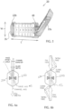
Fig. 3 is a perspective view of an embodiment of the tube slitter tool of the present invention in the closed position. -
Fig. 4 is a perspective view of the tube slitter ofFig. 3 in the open position according to the present invention. -
Fig. 5 is a top elevational view of the tube slitter ofFig. 3 in the open position according to the present invention. -
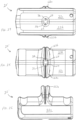
Figs. 6a and 6b are front cutaway views showing the blades of the tube slitter ofFig. 3 in the closed position. -
Figs. 7a and 7b show forces on the tube slitter ofFig. 3 in a semi-closed and closed position. -
Fig. 8 is a rear elevational view of the tube slitter ofFig. 3 in the closed position. -
Fig. 9 is a rear elevational view of the tube slitter ofFig. 3 in the open position. -
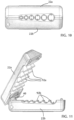
Fig. 10 is a side elevational view of the tube slitter ofFig. 3 in the closed position. -
Fig. 11 is a side elevational view of the tube slitter ofFig. 3 in the open position. -
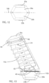
Fig. 12 is a front elevational view of the tube slitter ofFig. 3 in the closed position. -
Fig. 13 is a front elevational view of the tube slitter ofFig. 3 in the open position. -
Fig. 14 is a right front bottom perspective view of another embodiment of the tube slitter in the open position. -
Fig. 15 shows a bottom plan view of the tube slitter tool shown inFig. 14 . -
Fig. 16 is a left side cross-sectional view of the tube slitter ofFig. 15 in the closed position across cut lines 16-16. -
Fig. 17 is a right side elevational view of the tube slitter ofFig. 14 in the closed position according to the present invention. -
Fig. 18 is a bottom cross-sectional view of the tube slitter ofFig. 17 across cut lines 18-18. -
Fig. 19 s a left cross-sectional view of the tube slitter shown inFig. 14 . -
Fig. 20 is bottom cross-sectional view of the tube slitter shown inFig. 19 across cut lines 20-20. -
Fig. 21 is an exploded perspective view of the tube slitter ofFig. 14 showing one body portion with the storage forextra blades 26. -
Fig. 22 is a perspective view of the tube slitter ofFig. 14 in the open position. -
Fig. 23 is a perspective view of the tube slitter ofFig. 14 in the open position with a cable engaged in the groove of one body portion. -
Fig. 24 is a rear elevational perspective view of the tube slitter ofFig. 14 in the open position. -
Fig. 25 is a front elevational view of the tube slitter ofFig. 14 in the open position. -
Fig. 26 is a bottom plan view of the tube slitter ofFig. 14 in the open position. -
Fig. 27 is a perspective view of the tube slitter ofFig. 14 in the open position showing the hinge. -
Fig. 28 is a left elevational view of the tube slitter ofFig. 14 in the open position. -
Fig. 29 shows a front perspective view of the tube slitter in an open position. -
Fig. 30 is a left front top perspective view of the tube slitter ofFig. 14 in the open position. -
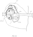
Fig. 31 is a front top perspective view of the tube slitter ofFig. 14 in the open position. -
Fig. 32 is a right front top perspective view of the tube slitter ofFig. 14 in the open position. -
Fig. 33 is an enlarged perspective view of a portion of the tube slitter ofFig. 14 showing the blade secured and extending into the groove. -
Fig. 34 is a perspective view of the tube slitter ofFig. 14 showing a method of using the tube slitter with an operator's hand grasping the tube slitter in the closed position with a cable or tube inserted through the opening formed by the concave surface. -
Fig. 35 is a perspective view of one tool portion half of the tube slitter according to a third embodiment of the present invention. -
Fig. 36 is a perspective view of the opposite tool portion half of the tube slitter engagable with the third embodiment shown inFig. 35 . -
Fig. 37 is a perspective view of the one tool portion half of the tube slitter shown inFig. 35 . - In describing the embodiment of the present invention, reference will be made herein to
Figs. 1-37 of the drawings in which like numerals refer to like features of the invention. - The tool of the present invention may be employed with a fixed blade to cut or slit a tube or cable, including cable jacket or insulation, to a desired depth set by the dimension of the blade. The tool of the present invention uses an angled hinge to rotate the blade(s) into the tube or cable jacket using the same motion as tool operation. This action eases the stress put on the tool operator. The instant tool does not need to rely on a clip to set the closed tool position, so it is more accurate than locking tools.
- A first embodiment of the tube slitter tool of the present invention is shown in
Figs. 3-13 . As shown inFigs. 3-5 ,tool 20 of the present invention has first and second body halves, identified asfirst body portion 22a andsecond body portion 22b joined at one end by off-axis hinge 40.Body portions Fig. 1 ) meet along a plane. Eachbody portion hinge 40 end of the body to theend grooves body portions grooves body portions blade 24.Blade 24 extends intosemi-cylindrical surfaces blade 24 is shown as being fixed, it is possible to employ blades whose depth may be adjusted. Instead of being integrally formed into and of one piece withbody portions grooves blades 24 may be provided as a cassette removable as a unit from withinbody portions common body portions axis hinge 40, to be configured for cable diameters and blade heights for different customers and applications. - The off-
axis hinge 40 is shown in more detail inFigs, 6a, 6b ,8, 9 ,11 and13 . InFigs. 6a and 6b , theopposite tool portions hinge 40 extends in a direction substantially in the direction of the width of the tool and at an acute offset angle to both i) the plane along which the first and secondopposite tool portions Fig. 6b . This reduces the strain on the operator because the need to drive the blades into the tube, cable or cable jacket is integrated into the natural pulling movement of the tool. - The pulling action of the tool with respect to the tube or cable creates twisting forces on the off-axis hinge. The instant tool supports those forces on the opposite, non-hinge, end of the tool using alignment features 80 that limit the twisting of the hinge. As shown in
Fig. 7 , the tool includes aface 92a on thefirst tool portion 22a which contacts theface 92b of thesecond tool portion 22b when the tool is in the closed position, thefaces plane 100. The alignment features 80 comprise at least oneprotrusion 82 on thefirst tool portion 22a and at least one correspondingdetent 84 on the toolsecond portion 22b. Theprotrusion 82 includes a top surface and tapered side walls extending from the top surface to thefirst tool face 92a. Thedetent 84 includes a bottom surface and tapered side walls extending from the bottom surface to thesecond tool face 92b. When first and secondopposite tool portions second tool portions arrow 70 to cut the tube or cable jacket with the blade causes the first and secondopposite tool portions arrows protrusion 82 may be nearly engaged with thecorresponding detent 84 as shown inFig. 7a , and as the cable is drawn through in the direction ofarrow 70, the force of the cable pulling thesecond portion 22b in the direction ofarrow 70 allows thehinge 40 to force thetool portions arrows hinge 40 to the toolportion top surfaces Fig. 7b . Additionally, the tool may be in the fully closed position before the cable is drawn in the direction ofarrow 70 and the drawing movement maintains the tool in the closed position. Thetool portions protrusion 82 on each of the tool portions22a, 22b engagable with adetent 84 on the opposition tool portion as shown in the embodiment ofFigs. 7a and 7b . - A second embodiment of the tube slitter tool 20' of the present invention is shown in
Figs. 14-34 . This embodiment includes a similar off-axis hinge 40 but includes only one opening formed by concave surface indentation, channel orgroove 31a, 31b across the width of the body portion configured to accept the shape of the tube orcable 50. The tool cylindrical opening diameter or width may be the same or slightly larger than the cable to be slit, to enable the cable to be slid through with respect to the tool body. Projecting into each of the semi-cylindrical surfaces on indentation, channel orgroove 31a, 31b of the body portions is a slitting or cuttingblade 24, which extends a distance of height sufficient to cut through the cable jacket, or otherwise make the desired cut in the tube orcable 50. In this embodiment, the body portion has extended from a side thereof a projection, consisting ofbody portions groove 31a, 31b extends. This projection increases the width of the tool, compared to the width ofbody portions Blades 24 may be located in this projection, beyond the sides of thebody portions -
Body portions Figs. 15, 17 and20 ). - The tube slitter tool 20' includes the first and second body portions or opposite tool portions or 22a, 22b, each tool portion including a common hinged portion at a first tool end for engaging the opposite tool portion. The first and second
opposite tool portions portion 40 between an open position and a closed, folded-together position, each of the first and secondopposite tool portions opposite tool portions concave surface 31a, 31b extending across the width W of at least one of the first andsecond tool portions concave surface 31a, 31b forming an opening 44, when the first and secondopposite tool portions 31a, 31b are in the closed position, through which a tube orcable 50 may be slid with respect to the tool 20'. - The tube or cable jacket slitting or cutting tool 20' includes a
blade 24 extending inward into the opening formed 44 by the at least one concave surface for slitting or cutting a depth of the tube or cable jacket as it is moved with respect to the tool 20'. The tube or cable jacket slitting or cutting tool 20' includes a hinge pivot axis 60 in the hinged portion extending in a direction substantially in the direction of the width W and at an acute angle to either the plane or to thelongitudinal axis 70 of the tube or cable in the opening formed by the at least oneconcave surface 31a, 31b. When the first and secondopposite tool portions cable 50 in the opening, theblade 24 cuts into the tube or cable outer jacket 52 and movement of the tube or cable 60 with respect to the tool 20' in one direction to slit or cut the tube or cable jacket 52 with theblade 24 causes the first and secondopposite tool portions tool portions projection projection blade 24 may extend inward into the opening formed by the at least oneconcave surface 31a, 31b in theprojection projection concave surface 31a, 31b andblade 24 may be removable as a unit from the at least one of the first and second tool portions. The tube or cable jacket slitting or cutting tool 20' may include at least oneconcave surface 31a, 31b formed into and extending across the width of each of the first andsecond tool portions concave surface 31a, 31b in eachtool portion concave surface cable 50 may be slid through the opening 44 with respect to the tool 20'. Extra or spare blades 26 (Fig. 21 ) may be secured in an interior portion of the tube slitter 20' with a spare blade fastener 27 and may be released using a fastener tool 28 secured in an interior portion of the slitting tool 20'. Alignment of the tool 20' in the closed position may be accomplished withmale alignment protrusions 46 engagingfemale alignment depressions 47 to provide stabilization of the tool 20' during the pulling action of the tool 20' with respect to the tube orcable 50, the pulling action producing a twisting force on the off-axis hinge 40. The instant tool supports those forces on the opposite, non-hinge, end of the tool using themale alignment protrusions 46 andfemale alignment depressions 47 that limit the twisting of the hinge. - A method of using the tube or cable slitting tool as described above and shown in
Fig. 34 includes ensuring the first and second tool portions are in an open position and placing a tube orcable 50 having an outer jacket into the opening formed by the at least one concave surface of the first orsecond tool portion second tool portions blade 24 extending inward into at opening31a, 31b cuts the tube orcable 50 outer jacket and drawing a portion of the tube orcable 50 with respect to the tool 10 in a parallel direction to the at least one concave surface of the first orsecond tool half blade 24 produces an elongated slit in the tube orcable 50 jacket. The method includes moving the tool 10 to the open position and removing the slit tube orcable 50 from the at least one concave surface of the first orsecond tool portion tube 50 through theopening 31a, 31b formed by the at least one concave surface in one direction causes the first and secondopposite tool portions projection opening 31a, 31b formed by the at least one concave surface extending through theprojection tube 50 through the at least one concave surface in one direction the projection extends between the tool operator's fingers when the user grasps the tool 10 with the fingers extend substantially around theclosed tool portions - In other words, after moving the first and second
tool body portions hinge 40 into the open position, without disassembling the tool 10, the tool operator places tube orcable 50 having an outer jacket in one concave surface , and then moves the first and second tool portions about the hinge to the closed position. An end or mid-span portion of the tube or cable may be placed in the tool. In the case of the second tool embodiment, the operator grasps the tool such that the fingers extend substantially around theclosed body portions projection projection Fig. 18 ), so that the blade makes an elongated slit in the tube or cable jacket. The tool is drawn in the direction of the arrow with respect to the cable. After moving the tool to the open position, the slit tube or cable may be removed from the tool body portion. - The articulating hinge of the tool allows accurate end and mid-span stripping without disassembling the tool. The user simply closes the tool over the cable and pulls to slit the jacket. The blades are shielded to provide safe operation and prevent cuts and lacerations to the operator's fingers. The tool body may be made with lightweight materials, such as a polymer, and has an ergonomic design with convenient opening tabs which fits comfortably in the operator's hand and requires minimal effort to use. The blades may be reversible blades, and additional replacement blades may be stowed conveniently inside the tool.
-
Figs. 35-37 are a perspective views of a third embodiment of the tube slitter and show the off-axis hinge 40 and thepin 41 allowing thefirst tool portion 22a' to rotatingly engage thesecond tool portion 22b'. The first orsecond tool portion 22a', 22b' includes a magnet 88 which is preferably a high strength earth magnet and the opposite tool portion includes an alloy dowel pin 89 which substantially contacts the magnet 88 when the tube slitter is in the closed position.Fig. 37 shows thesecond tool portion 22b' having the alloy dowel pin 89 secured in an opening 99 and the corresponding earth magnet 88 secured infirst tool portion 22a' aligned with the dowel pin 89 (the first tool portion not shown) when the tube slitter is in a partially open position.Figs. 35-37 additionally show a the off-axis hinge 40 andhinge pin 41 common to bothtool portions 22a', 22b'. The magnet 88 urges the allow dowel 89 toward the magnet 88 so that when the tool is in the closed position, the earth magnet 88 and allow dowel pin 89 secure the tool in a tightly closed position, maintaining the tight tolerances in slitting the cable ortube 50. - Thus, the present invention provides one or more of the following advantages: 1) The off-axis hinge transfers natural pulling pressure into blade engagement pressure. The tool is consistently held closed ensuring consistent cut depths. 2) The twist limiting features restricts over torqueing of hinge and supports off-axis loads generated by the hinge. 3) The tool is ergonomic convenient to the operator using one handed operation to hold the tool while pulling the tube or cable with the other hand.
- While the present invention has been particularly described, in conjunction with one or more specific embodiments, it is evident that many alternatives, modifications and variations will be apparent to those skilled in the art in light of the foregoing description.
- Thus, having described the invention, what is claimed is:
Claims (15)
- A tube or cable jacket slitting or cutting tool (20) comprising:first and second opposite tool portions (22a, 22b), each tool portion (22a, 22b) including a common hinged portion (40) at a first end for engaging the first and second opposite tool portions (22a, 22b), the first and second opposite tool portions (22a, 22b) being foldable about the hinged portion (40) between an open position and a closed, folded-together position, each of the first and second opposite tool portions (22a, 22b) having a length, width, and height, with the length extending in the direction from the hinged portion (40) at the one end to a second end (26a, 26b) opposite the hinge, the width extending in the direction perpendicular to the length, and the height extending in the direction perpendicular to the length and width, the first and second opposite tool portions (22a, 22b) meeting along a plane comprising the length and width when in the closed position;at least one concave surface (31a, 31b, 32a, 32b, 33a, 33b, 34a, 34b, 35a, 35b, 36a, 36b) extending across the width of at least one of the first and second tool portions (22a, 22b), the at least one concave surface forming an opening, when the first and second opposite tool portions (22a, 22b) are in the closed position, through which a tube or cable may be slid with respect to the tool (20);a blade (24) extending inward into the opening formed by the at least one concave surface (31a, 31b, 32a, 32b, 33a, 33b, 34a, 34b, 35a, 35b, 36a, 36b) for slitting or cutting a depth of the tube or cable jacket as it is moved with respect to the tool (20); characterised in that,a hinge pivot axis (60) in the hinged portion (40) extending in a direction substantially in the direction of the width and at an acute angle to either the plane or to the longitudinal axis (70) of the tube or cable in the opening formed by the at least one concave surface,wherein when the first and second opposite tool portions (22a, 22b) are folded to the closed position with the tube or cable in the opening, the blade (24) cuts into the tube or cable outer jacket and movement of the tube or cable with respect to the tool (20) in one direction to slit or cut the tube or cable jacket with the blade (24) causes the first and second opposite tool portions (22a, 22b) to be urged toward each other.
- The tool of claim 1 wherein each of the tool portions (22a, 22b) includes an alignment portion disposed near the second end and the first tool portion alignment portion is engagable with the second tool portion alignment portion for maintaining alignment of the tool when the tool (20) is in the closed position.
- The tool of claim 1 further including a projection extending from a side of first and second opposite tool portions (22a, 22b) in the direction of the tool width and wherein the at least one concave surface (31a, 31b, 32a, 32b, 33a, 33b, 34a, 34b, 35a, 35b, 36a, 36b) extends through the projection.
- The tool of claim 3 wherein the blade (24) extends inward into the opening formed by the at least one concave surface (31a, 31b, 32a, 32b, 33a, 33b, 34a, 34b, 35a, 35b, 36a, 36b) in the projection.
- The tool of claim 3 wherein the projection extends between a user's fingers when the user grasps the tool (20) with the fingers extend substantially around the closed tool portions (22a, 22b).
- The tool of claim 5 wherein the blade (24) extends inward into the opening formed by the at least one concave surface (31a, 31b, 32a, 32b, 33a, 33b, 34a, 34b, 35a, 35b, 36a, 36b) in the projection.
- The tool of claim 1 wherein the at least one concave surface (31a, 31b, 32a, 32b, 33a, 33b, 34a, 34b, 35a, 35b, 36a, 36b) and blade (24) are removable as a unit from the at least one of the first and second tool portions (22a, 22b).
- The tool of claim 1 including at least one concave surface (31a, 31b, 32a, 32b, 33a, 33b, 34a, 34b, 35a, 35b, 36a, 36b) formed into and extending across the width of each of the first and second tool portions (22a, 22b), the at least one concave surface in each tool portion (22a, 22b) being in alignment with the other concave surface to form an opening, wherein when the first and second opposite tool portions (22a, 22b) are in the closed position, the tube or cable may be slid through the opening with respect to the tool (20).
- The tool of claim 1 including a magnet (88) secured in the first or second tool portion (22a, 22b) and an alloy dowel pin (89) secured in the other of the first or second tool portion (22a, 22b) wherein the magnet (88) is disposed adjacent the alloy dowel pin (89) when the tool (20) is in the closed position, maintaining the tool (20) in the closed position when a tube is drawn through the tool (20).
- The tool (20) of claim 1 further comprising:a projection extending from a side of the first and second opposite tool portions (22a, 22b) in the direction of the tool width,wherein the at least one concave surface ((31a, 31b, 32a, 32b, 33a, 33b, 34a, 34b, 35a, 35b, 36a, 36b) extends through the projection, andwherein the blade (24) extends inward into the opening formed by the at least one concave surface in the projection for slitting or cutting a depth of the tube or cable jacket as it is moved with respect to the tool (20), wherein when the first and second opposite tool portions (22a, 22b) are folded to the closed position with the tube or cable in the opening, the blade (24) cuts into the tube or cable outer jacket and movement of the tube or cable with respect to the tool (20) in one direction causes the blade to cut the tube or cable jacket.
- A method of using the tube or cable slitting tool as described in claim 1 comprising:ensuring the first and second tool portions (22a, 22b) are in an open position;placing a tube or cable having an outer jacket into the opening formed by the at least one concave surface (31a, 31b, 32a, 32b, 33a, 33b, 34a, 34b, 35a, 35b, 36a, 36b) of the first or second tool portion (22a, 22b);moving the first and second tool portions (22a, 22b) to the closed position whereby the blade extending inward into at opening cuts the tube or cable outer jacket;drawing a portion of the tube or cable with respect to the tool (20) in a parallel direction to the at least one concave surface of the first or second tool half whereby the blade (24) produces an elongated slit in the tube or cable jacket;moving the tool (20) to the open position; andremoving the slit tube or cable from the at least one concave surface of the first or second tool portion (22a, 22b).
- The method of claim 11 wherein drawing the tube through the opening formed by the at least one concave surface (31a, 31b, 32a, 32b, 33a, 33b, 34a, 34b, 35a, 35b, 36a, 36b) in one direction causes the first and second opposite tool portions (22a, 22b) to be urged toward one another.
- The method of claim 12 wherein one or both of the tool portions (22a, 22b) includes a projection extending from a side thereof in the direction of the tool width, with the opening formed by the at least one concave surface (31a, 31b, 32a, 32b, 33a, 33b, 34a, 34b, 35a, 35b, 36a, 36b) extending through the projection, and wherein during drawing the tube through the at least one concave surface in one direction the projection extends between the tool operator's fingers when the user grasps the tool (20) with the fingers extend substantially around the closed tool portions (22a, 22b).
- The method of claim 13 wherein the blade (24) extends inward into the opening formed by the at least one concave surface (31a, 31b, 32a, 32b, 33a, 33b, 34a, 34b, 35a, 35b, 36a, 36b) in the projection.
- The method of claim 11 further comprising:
grasping the tool (20) with a user's fingers extend substantially around the closed tool portions (22a, 22b) wherein the projection extends between the tool operator's fingers.
Applications Claiming Priority (3)
| Application Number | Priority Date | Filing Date | Title |
|---|---|---|---|
| US201762572596P | 2017-10-16 | 2017-10-16 | |
| US201862725557P | 2018-08-31 | 2018-08-31 | |
| PCT/US2018/056067 WO2019079287A1 (en) | 2017-10-16 | 2018-10-16 | Tube slitter with off-axis hinge |
Publications (3)
| Publication Number | Publication Date |
|---|---|
| EP3697570A1 EP3697570A1 (en) | 2020-08-26 |
| EP3697570A4 EP3697570A4 (en) | 2021-07-21 |
| EP3697570B1 true EP3697570B1 (en) | 2023-09-27 |
Family
ID=66095767
Family Applications (1)
| Application Number | Title | Priority Date | Filing Date |
|---|---|---|---|
| EP18868493.0A Active EP3697570B1 (en) | 2017-10-16 | 2018-10-16 | Tube slitter with off-axis hinge |
Country Status (3)
| Country | Link |
|---|---|
| US (1) | US10795085B2 (en) |
| EP (1) | EP3697570B1 (en) |
| WO (1) | WO2019079287A1 (en) |
Families Citing this family (4)
| Publication number | Priority date | Publication date | Assignee | Title |
|---|---|---|---|---|
| US11493722B2 (en) * | 2020-10-16 | 2022-11-08 | Metra Electronics Corporation | Cable stripping tool |
| US12355221B2 (en) * | 2021-05-07 | 2025-07-08 | Hubbell Power Systems, Inc. | Shaving tool with upright handle |
| EP4367762B1 (en) * | 2021-07-09 | 2026-07-15 | Hubbell Power Systems, Inc. | Cable shaving tool |
| CN117533864A (en) * | 2023-12-18 | 2024-02-09 | 谢建武 | Double barrel paper cutter |
Family Cites Families (9)
| Publication number | Priority date | Publication date | Assignee | Title |
|---|---|---|---|---|
| US4081871A (en) | 1978-04-04 | 1978-04-04 | Knuth Everett F | Electrician's wire stripping tool |
| US5325587A (en) * | 1992-03-16 | 1994-07-05 | Rostra Tool Company | Wire stripper |
| WO2000033430A1 (en) * | 1998-11-30 | 2000-06-08 | The Siemon Company | Preparation tool for shielded cables |
| US8353107B2 (en) | 2008-06-03 | 2013-01-15 | Uraseal Inc. | Two-piece cable stripper |
| US9184575B2 (en) * | 2011-12-16 | 2015-11-10 | Sumitomo Electric Lightwave Corp. | Entry tool and methods for use for tubes or cables |
| DE202013102163U1 (en) | 2013-05-17 | 2013-07-01 | Krampe Immobilien Gmbh & Co. Kg | Deflashing tool for flat cables and round cables |
| US9819161B2 (en) * | 2015-03-13 | 2017-11-14 | Jonard Industries Corp. | Tube splitter |
| DE102015118439A1 (en) * | 2015-10-28 | 2017-05-04 | Weicon Gmbh & Co Kg | Coaxial cable tool |
| TWM554656U (en) * | 2017-10-03 | 2018-01-21 | 亨龍工業有限公司 | Cable stripping tool |
-
2018
- 2018-10-16 WO PCT/US2018/056067 patent/WO2019079287A1/en not_active Ceased
- 2018-10-16 EP EP18868493.0A patent/EP3697570B1/en active Active
- 2018-10-16 US US16/161,535 patent/US10795085B2/en active Active
Also Published As
| Publication number | Publication date |
|---|---|
| EP3697570A1 (en) | 2020-08-26 |
| WO2019079287A1 (en) | 2019-04-25 |
| EP3697570A4 (en) | 2021-07-21 |
| US20190113681A1 (en) | 2019-04-18 |
| US10795085B2 (en) | 2020-10-06 |
Similar Documents
| Publication | Publication Date | Title |
|---|---|---|
| US10795085B2 (en) | Tube slitter with off-axis hinge | |
| US6739217B2 (en) | Soft-grip wire stripper | |
| US4722140A (en) | Knife system | |
| CA2426412C (en) | Cutter knife for left-handed and right-handed persons | |
| US20110113633A1 (en) | Mid-span access tool for buffer tubes | |
| US5713132A (en) | Coaxial cable trimmer | |
| EP3326251B1 (en) | Stripping tool | |
| US5822863A (en) | Universal tool for accessing optical fibers in a fiber optic cable | |
| US20160268785A1 (en) | Tube splitter | |
| US20180095222A1 (en) | Sheath splitter and cutter | |
| US3447172A (en) | Electrician's tool | |
| US6079104A (en) | Stripping tool | |
| US20210245334A1 (en) | Hand tool structure | |
| US7089619B2 (en) | Multipurpose tool | |
| US5970615A (en) | Combined cutting and thinning shears | |
| KR101133235B1 (en) | cutter | |
| US20220203505A1 (en) | Hand tool structure | |
| US20210255413A1 (en) | Jacket removal tool for fiber optic cables | |
| US20070037444A1 (en) | Coaxial cable stripper | |
| US20250355182A1 (en) | Cable Slitter | |
| WO2020225325A1 (en) | Insulating-stripping tool designed as a hand tool, cutting part for an insulation-stripping tool and method for stripping a cable | |
| US20250262721A1 (en) | Multi-purpose cutting tool | |
| KR101463579B1 (en) | Multiple function tool | |
| EP1681140B1 (en) | Combination hairdressing scissor assembly | |
| US20240399542A1 (en) | Hand tool structure |
Legal Events
| Date | Code | Title | Description |
|---|---|---|---|
| STAA | Information on the status of an ep patent application or granted ep patent |
Free format text: STATUS: THE INTERNATIONAL PUBLICATION HAS BEEN MADE |
|
| PUAI | Public reference made under article 153(3) epc to a published international application that has entered the european phase |
Free format text: ORIGINAL CODE: 0009012 |
|
| STAA | Information on the status of an ep patent application or granted ep patent |
Free format text: STATUS: REQUEST FOR EXAMINATION WAS MADE |
|
| 17P | Request for examination filed |
Effective date: 20200325 |
|
| AK | Designated contracting states |
Kind code of ref document: A1 Designated state(s): AL AT BE BG CH CY CZ DE DK EE ES FI FR GB GR HR HU IE IS IT LI LT LU LV MC MK MT NL NO PL PT RO RS SE SI SK SM TR |
|
| AX | Request for extension of the european patent |
Extension state: BA ME |
|
| DAV | Request for validation of the european patent (deleted) | ||
| DAX | Request for extension of the european patent (deleted) | ||
| A4 | Supplementary search report drawn up and despatched |
Effective date: 20210622 |
|
| RIC1 | Information provided on ipc code assigned before grant |
Ipc: B25B 13/48 20060101AFI20210616BHEP Ipc: B25B 13/06 20060101ALI20210616BHEP Ipc: G02B 6/245 20060101ALI20210616BHEP Ipc: G02B 6/25 20060101ALI20210616BHEP Ipc: G02B 6/46 20060101ALI20210616BHEP Ipc: B26D 3/16 20060101ALI20210616BHEP |
|
| GRAP | Despatch of communication of intention to grant a patent |
Free format text: ORIGINAL CODE: EPIDOSNIGR1 |
|
| STAA | Information on the status of an ep patent application or granted ep patent |
Free format text: STATUS: GRANT OF PATENT IS INTENDED |
|
| RIC1 | Information provided on ipc code assigned before grant |
Ipc: B26D 3/16 20060101ALI20230313BHEP Ipc: G02B 6/46 20060101ALI20230313BHEP Ipc: G02B 6/25 20060101ALI20230313BHEP Ipc: G02B 6/245 20060101ALI20230313BHEP Ipc: B25B 13/06 20060101ALI20230313BHEP Ipc: B25B 13/48 20060101AFI20230313BHEP |
|
| INTG | Intention to grant announced |
Effective date: 20230413 |
|
| P01 | Opt-out of the competence of the unified patent court (upc) registered |
Effective date: 20230525 |
|
| RAP1 | Party data changed (applicant data changed or rights of an application transferred) |
Owner name: HUBBELL POWER SYSTEMS, INC. |
|
| GRAS | Grant fee paid |
Free format text: ORIGINAL CODE: EPIDOSNIGR3 |
|
| GRAA | (expected) grant |
Free format text: ORIGINAL CODE: 0009210 |
|
| STAA | Information on the status of an ep patent application or granted ep patent |
Free format text: STATUS: THE PATENT HAS BEEN GRANTED |
|
| AK | Designated contracting states |
Kind code of ref document: B1 Designated state(s): AL AT BE BG CH CY CZ DE DK EE ES FI FR GB GR HR HU IE IS IT LI LT LU LV MC MK MT NL NO PL PT RO RS SE SI SK SM TR |
|
| REG | Reference to a national code |
Ref country code: GB Ref legal event code: FG4D |
|
| REG | Reference to a national code |
Ref country code: CH Ref legal event code: EP |
|
| REG | Reference to a national code |
Ref country code: DE Ref legal event code: R096 Ref document number: 602018058430 Country of ref document: DE |
|
| REG | Reference to a national code |
Ref country code: IE Ref legal event code: FG4D |
|
| REG | Reference to a national code |
Ref country code: LT Ref legal event code: MG9D |
|
| PG25 | Lapsed in a contracting state [announced via postgrant information from national office to epo] |
Ref country code: GR Free format text: LAPSE BECAUSE OF FAILURE TO SUBMIT A TRANSLATION OF THE DESCRIPTION OR TO PAY THE FEE WITHIN THE PRESCRIBED TIME-LIMIT Effective date: 20231228 |
|
| PG25 | Lapsed in a contracting state [announced via postgrant information from national office to epo] |
Ref country code: SE Free format text: LAPSE BECAUSE OF FAILURE TO SUBMIT A TRANSLATION OF THE DESCRIPTION OR TO PAY THE FEE WITHIN THE PRESCRIBED TIME-LIMIT Effective date: 20230927 Ref country code: RS Free format text: LAPSE BECAUSE OF FAILURE TO SUBMIT A TRANSLATION OF THE DESCRIPTION OR TO PAY THE FEE WITHIN THE PRESCRIBED TIME-LIMIT Effective date: 20230927 Ref country code: NO Free format text: LAPSE BECAUSE OF FAILURE TO SUBMIT A TRANSLATION OF THE DESCRIPTION OR TO PAY THE FEE WITHIN THE PRESCRIBED TIME-LIMIT Effective date: 20231227 Ref country code: LV Free format text: LAPSE BECAUSE OF FAILURE TO SUBMIT A TRANSLATION OF THE DESCRIPTION OR TO PAY THE FEE WITHIN THE PRESCRIBED TIME-LIMIT Effective date: 20230927 Ref country code: LT Free format text: LAPSE BECAUSE OF FAILURE TO SUBMIT A TRANSLATION OF THE DESCRIPTION OR TO PAY THE FEE WITHIN THE PRESCRIBED TIME-LIMIT Effective date: 20230927 Ref country code: HR Free format text: LAPSE BECAUSE OF FAILURE TO SUBMIT A TRANSLATION OF THE DESCRIPTION OR TO PAY THE FEE WITHIN THE PRESCRIBED TIME-LIMIT Effective date: 20230927 Ref country code: GR Free format text: LAPSE BECAUSE OF FAILURE TO SUBMIT A TRANSLATION OF THE DESCRIPTION OR TO PAY THE FEE WITHIN THE PRESCRIBED TIME-LIMIT Effective date: 20231228 Ref country code: FI Free format text: LAPSE BECAUSE OF FAILURE TO SUBMIT A TRANSLATION OF THE DESCRIPTION OR TO PAY THE FEE WITHIN THE PRESCRIBED TIME-LIMIT Effective date: 20230927 |
|
| REG | Reference to a national code |
Ref country code: NL Ref legal event code: MP Effective date: 20230927 |
|
| REG | Reference to a national code |
Ref country code: AT Ref legal event code: MK05 Ref document number: 1614936 Country of ref document: AT Kind code of ref document: T Effective date: 20230927 |
|
| PG25 | Lapsed in a contracting state [announced via postgrant information from national office to epo] |
Ref country code: NL Free format text: LAPSE BECAUSE OF FAILURE TO SUBMIT A TRANSLATION OF THE DESCRIPTION OR TO PAY THE FEE WITHIN THE PRESCRIBED TIME-LIMIT Effective date: 20230927 |
|
| PG25 | Lapsed in a contracting state [announced via postgrant information from national office to epo] |
Ref country code: IS Free format text: LAPSE BECAUSE OF FAILURE TO SUBMIT A TRANSLATION OF THE DESCRIPTION OR TO PAY THE FEE WITHIN THE PRESCRIBED TIME-LIMIT Effective date: 20240127 |
|
| PG25 | Lapsed in a contracting state [announced via postgrant information from national office to epo] |
Ref country code: AT Free format text: LAPSE BECAUSE OF FAILURE TO SUBMIT A TRANSLATION OF THE DESCRIPTION OR TO PAY THE FEE WITHIN THE PRESCRIBED TIME-LIMIT Effective date: 20230927 |
|
| PG25 | Lapsed in a contracting state [announced via postgrant information from national office to epo] |
Ref country code: ES Free format text: LAPSE BECAUSE OF FAILURE TO SUBMIT A TRANSLATION OF THE DESCRIPTION OR TO PAY THE FEE WITHIN THE PRESCRIBED TIME-LIMIT Effective date: 20230927 |
|
| PG25 | Lapsed in a contracting state [announced via postgrant information from national office to epo] |
Ref country code: SM Free format text: LAPSE BECAUSE OF FAILURE TO SUBMIT A TRANSLATION OF THE DESCRIPTION OR TO PAY THE FEE WITHIN THE PRESCRIBED TIME-LIMIT Effective date: 20230927 Ref country code: RO Free format text: LAPSE BECAUSE OF FAILURE TO SUBMIT A TRANSLATION OF THE DESCRIPTION OR TO PAY THE FEE WITHIN THE PRESCRIBED TIME-LIMIT Effective date: 20230927 Ref country code: IS Free format text: LAPSE BECAUSE OF FAILURE TO SUBMIT A TRANSLATION OF THE DESCRIPTION OR TO PAY THE FEE WITHIN THE PRESCRIBED TIME-LIMIT Effective date: 20240127 Ref country code: ES Free format text: LAPSE BECAUSE OF FAILURE TO SUBMIT A TRANSLATION OF THE DESCRIPTION OR TO PAY THE FEE WITHIN THE PRESCRIBED TIME-LIMIT Effective date: 20230927 Ref country code: EE Free format text: LAPSE BECAUSE OF FAILURE TO SUBMIT A TRANSLATION OF THE DESCRIPTION OR TO PAY THE FEE WITHIN THE PRESCRIBED TIME-LIMIT Effective date: 20230927 Ref country code: CZ Free format text: LAPSE BECAUSE OF FAILURE TO SUBMIT A TRANSLATION OF THE DESCRIPTION OR TO PAY THE FEE WITHIN THE PRESCRIBED TIME-LIMIT Effective date: 20230927 Ref country code: AT Free format text: LAPSE BECAUSE OF FAILURE TO SUBMIT A TRANSLATION OF THE DESCRIPTION OR TO PAY THE FEE WITHIN THE PRESCRIBED TIME-LIMIT Effective date: 20230927 Ref country code: SK Free format text: LAPSE BECAUSE OF FAILURE TO SUBMIT A TRANSLATION OF THE DESCRIPTION OR TO PAY THE FEE WITHIN THE PRESCRIBED TIME-LIMIT Effective date: 20230927 Ref country code: PT Free format text: LAPSE BECAUSE OF FAILURE TO SUBMIT A TRANSLATION OF THE DESCRIPTION OR TO PAY THE FEE WITHIN THE PRESCRIBED TIME-LIMIT Effective date: 20240129 |
|
| PG25 | Lapsed in a contracting state [announced via postgrant information from national office to epo] |
Ref country code: PL Free format text: LAPSE BECAUSE OF FAILURE TO SUBMIT A TRANSLATION OF THE DESCRIPTION OR TO PAY THE FEE WITHIN THE PRESCRIBED TIME-LIMIT Effective date: 20230927 Ref country code: IT Free format text: LAPSE BECAUSE OF FAILURE TO SUBMIT A TRANSLATION OF THE DESCRIPTION OR TO PAY THE FEE WITHIN THE PRESCRIBED TIME-LIMIT Effective date: 20230927 |
|
| REG | Reference to a national code |
Ref country code: CH Ref legal event code: PL |
|
| REG | Reference to a national code |
Ref country code: BE Ref legal event code: MM Effective date: 20231031 |
|
| PG25 | Lapsed in a contracting state [announced via postgrant information from national office to epo] |
Ref country code: LU Free format text: LAPSE BECAUSE OF NON-PAYMENT OF DUE FEES Effective date: 20231016 |
|
| PG25 | Lapsed in a contracting state [announced via postgrant information from national office to epo] |
Ref country code: LU Free format text: LAPSE BECAUSE OF NON-PAYMENT OF DUE FEES Effective date: 20231016 |
|
| REG | Reference to a national code |
Ref country code: DE Ref legal event code: R097 Ref document number: 602018058430 Country of ref document: DE |
|
| PG25 | Lapsed in a contracting state [announced via postgrant information from national office to epo] |
Ref country code: MC Free format text: LAPSE BECAUSE OF FAILURE TO SUBMIT A TRANSLATION OF THE DESCRIPTION OR TO PAY THE FEE WITHIN THE PRESCRIBED TIME-LIMIT Effective date: 20230927 |
|
| PG25 | Lapsed in a contracting state [announced via postgrant information from national office to epo] |
Ref country code: DK Free format text: LAPSE BECAUSE OF FAILURE TO SUBMIT A TRANSLATION OF THE DESCRIPTION OR TO PAY THE FEE WITHIN THE PRESCRIBED TIME-LIMIT Effective date: 20230927 |
|
| PG25 | Lapsed in a contracting state [announced via postgrant information from national office to epo] |
Ref country code: CH Free format text: LAPSE BECAUSE OF NON-PAYMENT OF DUE FEES Effective date: 20231031 |
|
| PG25 | Lapsed in a contracting state [announced via postgrant information from national office to epo] |
Ref country code: MC Free format text: LAPSE BECAUSE OF FAILURE TO SUBMIT A TRANSLATION OF THE DESCRIPTION OR TO PAY THE FEE WITHIN THE PRESCRIBED TIME-LIMIT Effective date: 20230927 Ref country code: DK Free format text: LAPSE BECAUSE OF FAILURE TO SUBMIT A TRANSLATION OF THE DESCRIPTION OR TO PAY THE FEE WITHIN THE PRESCRIBED TIME-LIMIT Effective date: 20230927 Ref country code: CH Free format text: LAPSE BECAUSE OF NON-PAYMENT OF DUE FEES Effective date: 20231031 |
|
| PLBE | No opposition filed within time limit |
Free format text: ORIGINAL CODE: 0009261 |
|
| STAA | Information on the status of an ep patent application or granted ep patent |
Free format text: STATUS: NO OPPOSITION FILED WITHIN TIME LIMIT |
|
| PG25 | Lapsed in a contracting state [announced via postgrant information from national office to epo] |
Ref country code: BE Free format text: LAPSE BECAUSE OF NON-PAYMENT OF DUE FEES Effective date: 20231031 |
|
| 26N | No opposition filed |
Effective date: 20240628 |
|
| PG25 | Lapsed in a contracting state [announced via postgrant information from national office to epo] |
Ref country code: IE Free format text: LAPSE BECAUSE OF NON-PAYMENT OF DUE FEES Effective date: 20231016 |
|
| PG25 | Lapsed in a contracting state [announced via postgrant information from national office to epo] |
Ref country code: SI Free format text: LAPSE BECAUSE OF FAILURE TO SUBMIT A TRANSLATION OF THE DESCRIPTION OR TO PAY THE FEE WITHIN THE PRESCRIBED TIME-LIMIT Effective date: 20230927 |
|
| PG25 | Lapsed in a contracting state [announced via postgrant information from national office to epo] |
Ref country code: SI Free format text: LAPSE BECAUSE OF FAILURE TO SUBMIT A TRANSLATION OF THE DESCRIPTION OR TO PAY THE FEE WITHIN THE PRESCRIBED TIME-LIMIT Effective date: 20230927 Ref country code: IE Free format text: LAPSE BECAUSE OF NON-PAYMENT OF DUE FEES Effective date: 20231016 |
|
| PG25 | Lapsed in a contracting state [announced via postgrant information from national office to epo] |
Ref country code: BG Free format text: LAPSE BECAUSE OF FAILURE TO SUBMIT A TRANSLATION OF THE DESCRIPTION OR TO PAY THE FEE WITHIN THE PRESCRIBED TIME-LIMIT Effective date: 20230927 |
|
| PG25 | Lapsed in a contracting state [announced via postgrant information from national office to epo] |
Ref country code: BG Free format text: LAPSE BECAUSE OF FAILURE TO SUBMIT A TRANSLATION OF THE DESCRIPTION OR TO PAY THE FEE WITHIN THE PRESCRIBED TIME-LIMIT Effective date: 20230927 |
|
| PG25 | Lapsed in a contracting state [announced via postgrant information from national office to epo] |
Ref country code: CY Free format text: LAPSE BECAUSE OF FAILURE TO SUBMIT A TRANSLATION OF THE DESCRIPTION OR TO PAY THE FEE WITHIN THE PRESCRIBED TIME-LIMIT; INVALID AB INITIO Effective date: 20181016 |
|
| PG25 | Lapsed in a contracting state [announced via postgrant information from national office to epo] |
Ref country code: HU Free format text: LAPSE BECAUSE OF FAILURE TO SUBMIT A TRANSLATION OF THE DESCRIPTION OR TO PAY THE FEE WITHIN THE PRESCRIBED TIME-LIMIT; INVALID AB INITIO Effective date: 20181016 |
|
| PGFP | Annual fee paid to national office [announced via postgrant information from national office to epo] |
Ref country code: GB Payment date: 20250911 Year of fee payment: 8 |
|
| PGFP | Annual fee paid to national office [announced via postgrant information from national office to epo] |
Ref country code: FR Payment date: 20250912 Year of fee payment: 8 |
|
| PG25 | Lapsed in a contracting state [announced via postgrant information from national office to epo] |
Ref country code: TR Free format text: LAPSE BECAUSE OF FAILURE TO SUBMIT A TRANSLATION OF THE DESCRIPTION OR TO PAY THE FEE WITHIN THE PRESCRIBED TIME-LIMIT Effective date: 20230927 |
|
| PGFP | Annual fee paid to national office [announced via postgrant information from national office to epo] |
Ref country code: DE Payment date: 20250912 Year of fee payment: 8 |