EP3697173A1 - Variable power water heater - Google Patents
Variable power water heater Download PDFInfo
- Publication number
- EP3697173A1 EP3697173A1 EP19215672.7A EP19215672A EP3697173A1 EP 3697173 A1 EP3697173 A1 EP 3697173A1 EP 19215672 A EP19215672 A EP 19215672A EP 3697173 A1 EP3697173 A1 EP 3697173A1
- Authority
- EP
- European Patent Office
- Prior art keywords
- controller
- power
- heating element
- identifier
- water heater
- Prior art date
- Legal status (The legal status is an assumption and is not a legal conclusion. Google has not performed a legal analysis and makes no representation as to the accuracy of the status listed.)
- Granted
Links
Images


Classifications
-
- F—MECHANICAL ENGINEERING; LIGHTING; HEATING; WEAPONS; BLASTING
- F24—HEATING; RANGES; VENTILATING
- F24H—FLUID HEATERS, e.g. WATER OR AIR HEATERS, HAVING HEAT-GENERATING MEANS, e.g. HEAT PUMPS, IN GENERAL
- F24H9/00—Details
- F24H9/20—Arrangement or mounting of control or safety devices
- F24H9/2007—Arrangement or mounting of control or safety devices for water heaters
- F24H9/2014—Arrangement or mounting of control or safety devices for water heaters using electrical energy supply
- F24H9/2021—Storage heaters
-
- F—MECHANICAL ENGINEERING; LIGHTING; HEATING; WEAPONS; BLASTING
- F24—HEATING; RANGES; VENTILATING
- F24H—FLUID HEATERS, e.g. WATER OR AIR HEATERS, HAVING HEAT-GENERATING MEANS, e.g. HEAT PUMPS, IN GENERAL
- F24H9/00—Details
- F24H9/20—Arrangement or mounting of control or safety devices
- F24H9/2007—Arrangement or mounting of control or safety devices for water heaters
- F24H9/2014—Arrangement or mounting of control or safety devices for water heaters using electrical energy supply
-
- F—MECHANICAL ENGINEERING; LIGHTING; HEATING; WEAPONS; BLASTING
- F24—HEATING; RANGES; VENTILATING
- F24H—FLUID HEATERS, e.g. WATER OR AIR HEATERS, HAVING HEAT-GENERATING MEANS, e.g. HEAT PUMPS, IN GENERAL
- F24H1/00—Water heaters, e.g. boilers, continuous-flow heaters or water-storage heaters
- F24H1/18—Water-storage heaters
-
- F—MECHANICAL ENGINEERING; LIGHTING; HEATING; WEAPONS; BLASTING
- F24—HEATING; RANGES; VENTILATING
- F24H—FLUID HEATERS, e.g. WATER OR AIR HEATERS, HAVING HEAT-GENERATING MEANS, e.g. HEAT PUMPS, IN GENERAL
- F24H1/00—Water heaters, e.g. boilers, continuous-flow heaters or water-storage heaters
- F24H1/18—Water-storage heaters
- F24H1/20—Water-storage heaters with immersed heating elements, e.g. electric elements or furnace tubes
- F24H1/201—Water-storage heaters with immersed heating elements, e.g. electric elements or furnace tubes using electric energy supply
-
- F—MECHANICAL ENGINEERING; LIGHTING; HEATING; WEAPONS; BLASTING
- F24—HEATING; RANGES; VENTILATING
- F24H—FLUID HEATERS, e.g. WATER OR AIR HEATERS, HAVING HEAT-GENERATING MEANS, e.g. HEAT PUMPS, IN GENERAL
- F24H15/00—Control of fluid heaters
- F24H15/20—Control of fluid heaters characterised by control inputs
- F24H15/212—Temperature of the water
- F24H15/223—Temperature of the water in the water storage tank
-
- F—MECHANICAL ENGINEERING; LIGHTING; HEATING; WEAPONS; BLASTING
- F24—HEATING; RANGES; VENTILATING
- F24H—FLUID HEATERS, e.g. WATER OR AIR HEATERS, HAVING HEAT-GENERATING MEANS, e.g. HEAT PUMPS, IN GENERAL
- F24H15/00—Control of fluid heaters
- F24H15/30—Control of fluid heaters characterised by control outputs; characterised by the components to be controlled
- F24H15/355—Control of heat-generating means in heaters
- F24H15/37—Control of heat-generating means in heaters of electric heaters
-
- F—MECHANICAL ENGINEERING; LIGHTING; HEATING; WEAPONS; BLASTING
- F24—HEATING; RANGES; VENTILATING
- F24H—FLUID HEATERS, e.g. WATER OR AIR HEATERS, HAVING HEAT-GENERATING MEANS, e.g. HEAT PUMPS, IN GENERAL
- F24H15/00—Control of fluid heaters
- F24H15/40—Control of fluid heaters characterised by the type of controllers
- F24H15/407—Control of fluid heaters characterised by the type of controllers using electrical switching, e.g. TRIAC
-
- F—MECHANICAL ENGINEERING; LIGHTING; HEATING; WEAPONS; BLASTING
- F24—HEATING; RANGES; VENTILATING
- F24H—FLUID HEATERS, e.g. WATER OR AIR HEATERS, HAVING HEAT-GENERATING MEANS, e.g. HEAT PUMPS, IN GENERAL
- F24H15/00—Control of fluid heaters
- F24H15/40—Control of fluid heaters characterised by the type of controllers
- F24H15/414—Control of fluid heaters characterised by the type of controllers using electronic processing, e.g. computer-based
- F24H15/421—Control of fluid heaters characterised by the type of controllers using electronic processing, e.g. computer-based using pre-stored data
-
- H—ELECTRICITY
- H02—GENERATION; CONVERSION OR DISTRIBUTION OF ELECTRIC POWER
- H02M—APPARATUS FOR CONVERSION BETWEEN AC AND AC, BETWEEN AC AND DC, OR BETWEEN DC AND DC, AND FOR USE WITH MAINS OR SIMILAR POWER SUPPLY SYSTEMS; CONVERSION OF DC OR AC INPUT POWER INTO SURGE OUTPUT POWER; CONTROL OR REGULATION THEREOF
- H02M1/00—Details of apparatus for conversion
- H02M1/08—Circuits specially adapted for the generation of control voltages for semiconductor devices incorporated in static converters
-
- H—ELECTRICITY
- H05—ELECTRIC TECHNIQUES NOT OTHERWISE PROVIDED FOR
- H05B—ELECTRIC HEATING; ELECTRIC LIGHT SOURCES NOT OTHERWISE PROVIDED FOR; CIRCUIT ARRANGEMENTS FOR ELECTRIC LIGHT SOURCES, IN GENERAL
- H05B1/00—Details of electric heating devices
- H05B1/02—Automatic switching arrangements specially adapted to apparatus ; Control of heating devices
- H05B1/0227—Applications
- H05B1/0252—Domestic applications
- H05B1/0275—Heating of spaces, e.g. rooms, wardrobes
- H05B1/0283—For heating of fluids, e.g. water heaters
Definitions
- Water heaters are typically designed with fixed hardware for powering their heating elements. This hardware may have fixed power requirements. Consequently, an entire water heater, or at least the hardware for powering its heating element, may need to be changed when the water heater is implemented in a facility (e.g., an aircraft or other passenger vehicle, a building, etc.) that does not meet the power requirements of the water heater.
- a facility e.g., an aircraft or other passenger vehicle, a building, etc.
- variable power water heater includes a water tank, a heating element, a power supply circuit, a switch, and a controller.
- the heating element may be disposed within or coupled to the water tank.
- the power supply circuit may be configured to generate a power signal for the heating element.
- the switch may be configured to couple the power supply circuit to the heating element, and the controller may be configured to toggle the switch according to a pulse width modulation (PWM) scheme to control a duty cycle of the power signal transmitted from the power supply circuit to the heating element.
- PWM pulse width modulation
- the switch may include or may be a triac.
- the controller may be further configured to detect an identifier and determine the PWM scheme based on the identifier.
- the controller may be configured to detect the identifier via an interface connection between the controller and an aircraft communication system and/or an aircraft power system.
- the controller may be configured to determine the PWM scheme based on the identifier by comparing the identifier with a lookup table including a plurality of identifiers and a plurality of PWM schemes corresponding to the plurality of identifiers.
- the controller may be configured to set the PWM scheme to a default PWM scheme when the controller is unable to detect the identifier.
- the controller may be configured to detect one or more power source characteristics and determine the PWM scheme based on the one or more power source characteristics.
- the controller may be configured to detect the one or more power source characteristics via an interface connection between the controller and an aircraft communication system and/or an aircraft power system.
- the controller may be configured to determine the PWM scheme by calculating the duty cycle of the power signal based on the one or more power source characteristics.
- the power supply circuit and the controller may be integrated into a combined power supply and control circuit.
- a control system for a variable power water heater includes a power supply circuit, a switch, and a controller.
- the power supply circuit may be configured to generate a power signal for a heating element of the variable power water heater.
- the switch may be configured to couple the power supply circuit to the heating element, and the controller may be configured to toggle the switch according to a PWM scheme to control a duty cycle of the power signal transmitted from the power supply circuit to the heating element.
- the switch may include or may be a triac.
- the controller may be further configured to detect an identifier and determine the PWM scheme based on the identifier.
- the controller may be configured to detect the identifier via an interface connection between the controller and an aircraft communication system and/or an aircraft power system.
- the controller may be configured to determine the PWM scheme based on the identifier by comparing the identifier with a lookup table including a plurality of identifiers and a plurality of PWM schemes corresponding to the plurality of identifiers.
- the controller may be configured to set the PWM scheme to a default PWM scheme when the controller is unable to detect the identifier.
- the controller may be configured to detect one or more power source characteristics and determine the PWM scheme based on the one or more power source characteristics.
- the controller may be configured to detect the one or more power source characteristics via an interface connection between the controller and an aircraft communication system and/or an aircraft power system.
- the controller may be configured to determine the PWM scheme by calculating the duty cycle of the power signal based on the one or more power source characteristics.
- the power supply circuit and the controller may be integrated into a combined power supply and control circuit.
- a method of controlling a variable power water heater includes: generating a power signal for a heating element; detecting an identifier or one or more power source characteristics; determining a PWM scheme based on the identifier or the one or more power source characteristics; and toggling a switch that delivers the power signal to the heating element according to the PWM scheme to control a duty cycle of the power signal.
- a letter following a reference numeral is intended to reference an embodiment of the feature or element that may be similar, but not necessarily identical, to a previously described element or feature bearing the same reference numeral (e.g., 1, 1a, 1b).
- reference numeral e.g. 1, 1a, 1b
- Such shorthand notations are used for purposes of convenience only and should not be construed to limit the disclosure in any way unless expressly stated to the contrary.
- any reference to “one embodiment” or “some embodiments” means that a particular element, feature, structure, or characteristic described in connection with the embodiment is included in at least one embodiment disclosed herein.
- the appearances of the phrase “in some embodiments” in various places in the specification are not necessarily all referring to the same embodiment, and embodiments may include one or more of the features expressly described or inherently present herein, or any combination of subcombination of two or more such features, along with any other features which may not necessarily be expressly described or inherently present in the instant disclosure.
- variable power water heater is disclosed.
- water heaters are designed with fixed hardware for powering their heating elements. This hardware may have fixed power requirements. Consequently, an entire water heater, or at least the hardware for powering its heating element, may need to be changed when the water heater is implemented in a facility (e.g., an aircraft or other passenger vehicle, a building, etc.) that does not meet the power requirements of the water heater.
- the variable power water heater disclosed herein is a software-controlled water heater that can adjust its duty cycle to meet selected power requirements or power budget of an aircraft or any other setting/facility in which the variable power water heater is installed
- variable power water heater may be configured for use in a variety of settings or facilities, such as, but not limited to, an aircraft lavatory (e.g., for a faucet, shower, etc.), an aircraft galley (e.g., for a coffee maker, faucet, dishwasher, etc.), or any other vehicle or building facility.
- an aircraft lavatory e.g., for a faucet, shower, etc.
- an aircraft galley e.g., for a coffee maker, faucet, dishwasher, etc.
- the variable power water heater and/or control system for the variable power water heater may be implemented in any other setting or facility.
- the examples and embodiments provided herein are not intended as limitations of the present disclosure unless otherwise specified in the claims.
- FIG. 1A is a block diagram illustrating an aircraft environment/system 100 that includes a variable power water heater 101, in accordance with one or more embodiments of this disclosure.
- the variable power water heater 101 includes a water tank 104, a heating element 102, a power supply circuit 106, a switch 110, and a controller 112.
- one or more of the components may be structurally separate from the variable power water heater 101.
- the power supply circuit 106, switch 110, and/or controller 112 may be coupled to the variable power water heater 101 via an external connection interface (e.g., an external port or connector).
- the heating element (or elements) 102 may be disposed within or coupled to the water tank 104.
- the heating element 102 may be disposed within the water tank 104 such that the heating element 102 becomes at least partially submerged when the water tank 104 is filled.
- the heating element 102 (or another (e.g., second, third, etc.) heating element 102) may be coupled to a side or bottom portion of the water tank 104.
- the heating element 102 may be coupled or otherwise held in contact with an internal or external side or bottom surface of the water tank 102.
- the heating element 102 (or elements) may be configured to heat one or more tubes or pipes that flow the water.
- the variable power water heater 101 may be a tankless water heater and/or configured with an auxiliary heating system.
- the water tank 104 or heated tube/pipe may be continuously or periodically filled by portable water supplied from a main water tank of the aircraft.
- the power supply circuit 106 may be configured to generate a power signal for the heating element 102.
- the power supply circuit 106 e.g., a power supply unit (PSU), or the like
- the power supply circuit 106 may be connected to an aircraft power system 108.
- the aircraft power system 108 is configured to supply 115V, 400Hz aircraft power.
- the aircraft power system 108 may be configured to provide aircraft power at other voltages (e.g., at any voltage in the range of 100-240V, etc.) or other frequencies (e.g., at any frequency in the range of 100-1000Hz, etc.).
- the switch 110 may be configured to couple the power supply circuit 106 to the heating element 102.
- the switch 110 can be configured to connect the power supply circuit 106 to the heating element 102 in a closed state and disconnect the power supply circuit 106 from the heating element 102 in an open state.
- the switch 110 is part of the power supply circuit 106.
- the switch 110 is a separate component disposed in between the power supply circuit 106 and the heating element 102.
- the switch 110 may be a triac (also known as a bidirectional triode thyristor or bilateral triode thyristor) or any other electrical or electromechanical switch element that connects the power supply circuit 106 to the heating element 102.
- the controller 112 may be configured to toggle the switch 110 according to a pulse width modulation (PWM) scheme to control a duty cycle of the power signal transmitted from the power supply circuit 106 to the heating element 102.
- PWM pulse width modulation
- the controller 112 may include a processor 118, memory 120, and a communication interface 122.
- the processor 118 provides processing functionality for at least the controller 112 and can include any number of processors, micro-controllers, circuitry, field programmable gate array (FPGA) or other processing systems, and resident or external memory for storing data, executable code, and other information accessed or generated by the controller 112.
- the processor 118 can execute one or more software programs embodied in a non-transitory computer readable medium (e.g., memory 120) that implement techniques described herein.
- the processor 118 is not limited by the materials from which it is formed, or the processing mechanisms employed therein and, as such, can be implemented via semiconductor(s) and/or transistors (e.g., using electronic integrated circuit (IC) components), and so forth.
- the memory 120 can be an example of tangible, computer-readable storage medium that provides storage functionality to store various data and/or program code associated with operation of the controller 112/processor 118, such as software programs and/or code segments, or other data to instruct the processor 118, and possibly other components of the controller 112, to perform the functionality described herein.
- the memory 120 can store data, such as a program of instructions for operating the controller 112, including its components (e.g., processor 118, communication interface 122, etc.), and so forth.
- processor 118 e.g., communication interface 122, etc.
- memory 120 can be an example of tangible, computer-readable storage medium that provides storage functionality to store various data and/or program code associated with operation of the controller 112/processor 118, such as software programs and/or code segments, or other data to instruct the processor 118, and possibly other components of the controller 112, to perform the functionality described herein.
- the memory 120 can store data, such as a program of instructions for operating the controller 112, including its components (e.g., processor
- the memory 120 can be integral with the processor 118, can comprise stand-alone memory, or can be a combination of both.
- Some examples of the memory 120 can include removable and non-removable memory components, such as random-access memory (RAM), read-only memory (ROM), flash memory (e.g., a secure digital (SD) memory card, a mini-SD memory card, and/or a micro-SD memory card), solid-state drive (SSD) memory, magnetic memory, optical memory, universal serial bus (USB) memory devices, hard disk memory, external memory, and so forth.
- RAM random-access memory
- ROM read-only memory
- flash memory e.g., a secure digital (SD) memory card, a mini-SD memory card, and/or a micro-SD memory card
- SSD solid-state drive
- magnetic memory magnetic memory
- optical memory optical memory
- USB universal serial bus
- the communication interface 122 can be operatively configured to communicate with components of the controller 112.
- the communication interface 122 can be configured to retrieve data from the processor 118 or other devices (e.g., aircraft power system 108, aircraft communication system 114, a temperature sensor (e.g., for sensing water temperature), user interface 116, etc.), transmit data for storage in the memory 120, retrieve data from storage in the memory 120, and so forth.
- the communication interface 122 can also be communicatively coupled with the processor 118 to facilitate data transfer between components of the controller 112 and the processor 118.
- the communication interface 122 is described as a component of the controller 112, one or more components of the communication interface 122 can be implemented as external components communicatively coupled to the controller 112 via a wired and/or wireless connection.
- the controller 112 can also include and/or connect to one or more input/output (I/O) devices (e.g., user interface 116 or other human machine interface (HMI) devices) via the communication interface 122.
- I/O input/output
- HMI human machine interface
- the communication interface 122 may include a transmitter, receiver, transceiver, physical connection interface, or any combination thereof.
- the power supply circuit 106 may include fixed hardware, and the power to the heating element 102 may be varied by toggling the switch 110 via the controller 112 to implement a selected PWM scheme.
- the power supply circuit 106 and the controller 112 may be integrated into a combined power supply and control circuit 124.
- the power supply and control circuit 124 may be configured to output a PWM power signal with a controlled duty cycle.
- the controller 112 may be configured to execute software to determine an identifier (e.g., power system identifier, aircraft type, etc.) or one or more power source characteristics (e.g., supported wattage) and control the duty cycle of the power signal to power the heating element 102 according to the power source characteristics/requirements of the aircraft.
- the controller 112 is configured to detect an identifier and determine the PWM scheme based on the identifier.
- the controller 112 may be configured to detect the identifier via an interface connection (e.g., identifier code sequence or programming detected via one or more connector pins) between the controller 112 and an aircraft communication system 114 (e.g., Controller Area Network (CAN) data bus, or the like) and/or the aircraft power system 108 itself.
- the controller 112 can be configured to receive the identifier in a data signal communicated via the aircraft communication system 114 or via user interface 116.
- the controller 112 may be configured to determine the PWM scheme based on the identifier by comparing the identifier with a lookup table including a plurality of identifiers and a plurality of PWM schemes corresponding to the plurality of identifiers. For example, various aircraft types and/or power systems may be stored in a listing with corresponding PWM schemes or duty cycles for achieving the target power requirements for the aircraft.
- the controller 112 is configured to detect one or more power source characteristics and determine the PWM scheme based on the one or more power source characteristics.
- the controller 112 may be configured to detect the one or more power source characteristics via an interface connection (e.g., code sequence or programming detected via one or more connector pins) between the controller 112 and an aircraft communication system 114 (e.g., Controller Area Network (CAN) data bus, or the like) and/or the aircraft power system 108 itself.
- the controller 112 can be configured to receive the one or more power source characteristics in a data signal communicated via the aircraft communication system 114 or via user interface 116.
- the controller 112 may be configured to determine the PWM scheme by calculating the duty cycle of the power signal based on the one or more power source characteristics. For example, the controller 112 can be configured to calculate a duty cycle based on the one or more detected power source characteristics (e.g., based on supported wattage) for the aircraft. The controller 112 can be further configured to determine the PWM scheme for achieving the calculated duty cycle. Alternatively, the controller 112 may be configured to determine the PWM scheme based on the one or more power source characteristics by comparing the one or more power source characteristics with a lookup table including a plurality of power source characteristics and a plurality of PWM schemes corresponding to the different power source characteristics. For example, various power source characteristics (e.g., values or ranges of power requirements, supported wattages, etc.) may be stored in a listing with corresponding PWM schemes or duty cycles for achieving the target power requirements for the aircraft.
- various power source characteristics e.g., values or ranges of power requirements, supported wattages, etc.
- the controller 112 may be configured to set the PWM scheme to a default PWM scheme.
- the controller 112 may be configured to set the PWM scheme to a PWM scheme associated with a default duty cycle (e.g., 70% duty cycle, 60% duty cycle, 50% duty cycle, or less).
- the controller 112 is communicatively coupled to a user interface 116.
- the controller 112 may be configured to receive a user-input temperature setting, duty cycle, identifier, power source characteristics, and/or power requirement via the user interface 116.
- the user interface 116 may include, but is not limited to, a display, a touchscreen display, touch panel, touchpad, keyboard, keypad, knob, buttons, switches, or any combination thereof.
- the user interface 116 comprises a personal electronic device (e.g., mobile device, personal computer, etc.) that is communicatively coupled to the controller 112 via the aircraft communication system 114.
- the user interface 116 can be used to override the controller programming, for example, to manually set the duty cycle or target power level/requirement.
- FIG. 2 illustrates one or more embodiments of a method 200 for controlling the variable power water heater 101 described herein.
- any steps or operations of disclosed processes e.g., method 200 may be performed in an arbitrary order, unless otherwise provided in the claims.
- the method 200 includes generating a power signal for a heating element 102.
- the power supply circuit 106 may be configured to generate a power signal for the heating element 102.
- the method 200 includes detecting an identifier or one or more power source characteristics.
- the controller 112 may be configured to detect the identifier or the one or more power source characteristics via an interface connection between the controller 112 and the aircraft communication system 114 and/or the aircraft power system 108.
- the controller 112 can be configured to receive the identifier or the one or more power source characteristics in a data signal communicated via the aircraft communication system 114 or via user interface 116.
- the method 200 includes determining a PWM scheme based on the identifier or the one or more power source characteristics.
- the controller 112 may be configured to determine the PWM scheme based on the identifier by comparing the identifier with a lookup table including a plurality of identifiers and a plurality of PWM schemes corresponding to the plurality of identifiers.
- the controller 112 can be configured to calculate a duty cycle based on the one or more detected power source characteristics and further configured to determine the PWM scheme for achieving the calculated duty cycle.
- the controller 112 may be configured to determine the PWM scheme based on the one or more power source characteristics by comparing the one or more power source characteristics with a lookup table including a plurality of power source characteristics and a plurality of PWM schemes corresponding to the different power source characteristics.
- the method 200 includes toggling a switch that delivers the power signal to the heating element according to the PWM scheme to control a duty cycle of the power signal.
- the controller 112 may be configured to toggle the switch 110 according to the selected, calculated, or otherwise determined PWM scheme to control a duty cycle of the power signal transmitted from the power supply circuit 106 to the heating element 102.
- water in the water tank 104 and/or heated tube/pipe can be heated by the heating element 102, and the power to the heating element 102 can be controlled by toggling the switch 110 according to the PWM-driven duty cycle to achieve target power requirements for the aircraft.
- the method 200 may further include any step or operation implied or required by one or more embodiments of the variable power water heater 101/system 100 described herein.
- the variable power water heater 101/system 100 can also include any additional component or functionality expressed or implied by one or more embodiments of the method 200.
- implementations of the methods disclosed herein may include one or more of the steps described herein. Further, such steps may be carried out in any desired order and two or more of the steps may be carried out simultaneously with one another. Two or more of the steps disclosed herein may be combined in a single step, and in some implementations, one or more of the steps may be carried out as two or more sub-steps. Further, other steps or sub-steps may be carried in addition to, or as substitutes to one or more of the steps disclosed herein.
Landscapes
- Engineering & Computer Science (AREA)
- Physics & Mathematics (AREA)
- Thermal Sciences (AREA)
- Chemical & Material Sciences (AREA)
- Combustion & Propulsion (AREA)
- Mechanical Engineering (AREA)
- General Engineering & Computer Science (AREA)
- Computer Hardware Design (AREA)
- Power Engineering (AREA)
- Control Of Resistance Heating (AREA)
- Resistance Heating (AREA)
- Heat-Pump Type And Storage Water Heaters (AREA)
Abstract
Description
- Water heaters are typically designed with fixed hardware for powering their heating elements. This hardware may have fixed power requirements. Consequently, an entire water heater, or at least the hardware for powering its heating element, may need to be changed when the water heater is implemented in a facility (e.g., an aircraft or other passenger vehicle, a building, etc.) that does not meet the power requirements of the water heater.
- A variable power water heater is disclosed. In embodiments, the variable power water heater includes a water tank, a heating element, a power supply circuit, a switch, and a controller. The heating element may be disposed within or coupled to the water tank. The power supply circuit may be configured to generate a power signal for the heating element. The switch may be configured to couple the power supply circuit to the heating element, and the controller may be configured to toggle the switch according to a pulse width modulation (PWM) scheme to control a duty cycle of the power signal transmitted from the power supply circuit to the heating element.
- In some embodiments of the variable power water heater, the switch may include or may be a triac.
- In some embodiments of the variable power water heater, the controller may be further configured to detect an identifier and determine the PWM scheme based on the identifier.
- In some embodiments of the variable power water heater, the controller may be configured to detect the identifier via an interface connection between the controller and an aircraft communication system and/or an aircraft power system.
- In some embodiments of the variable power water heater, the controller may be configured to determine the PWM scheme based on the identifier by comparing the identifier with a lookup table including a plurality of identifiers and a plurality of PWM schemes corresponding to the plurality of identifiers.
- In some embodiments of the variable power water heater, the controller may be configured to set the PWM scheme to a default PWM scheme when the controller is unable to detect the identifier.
- In some embodiments of the variable power water heater, the controller may be configured to detect one or more power source characteristics and determine the PWM scheme based on the one or more power source characteristics.
- In some embodiments of the variable power water heater, the controller may be configured to detect the one or more power source characteristics via an interface connection between the controller and an aircraft communication system and/or an aircraft power system.
- In some embodiments of the variable power water heater, the controller may be configured to determine the PWM scheme by calculating the duty cycle of the power signal based on the one or more power source characteristics.
- In some embodiments of the variable power water heater, the power supply circuit and the controller may be integrated into a combined power supply and control circuit.
- A control system for a variable power water heater is also disclosed. In embodiments, the control system includes a power supply circuit, a switch, and a controller. The power supply circuit may be configured to generate a power signal for a heating element of the variable power water heater. The switch may be configured to couple the power supply circuit to the heating element, and the controller may be configured to toggle the switch according to a PWM scheme to control a duty cycle of the power signal transmitted from the power supply circuit to the heating element.
- In some embodiments of the control system, the switch may include or may be a triac.
- In some embodiments of the control system, the controller may be further configured to detect an identifier and determine the PWM scheme based on the identifier.
- In some embodiments of the control system, the controller may be configured to detect the identifier via an interface connection between the controller and an aircraft communication system and/or an aircraft power system.
- In some embodiments of the control system, the controller may be configured to determine the PWM scheme based on the identifier by comparing the identifier with a lookup table including a plurality of identifiers and a plurality of PWM schemes corresponding to the plurality of identifiers.
- In some embodiments of the control system, the controller may be configured to set the PWM scheme to a default PWM scheme when the controller is unable to detect the identifier.
- In some embodiments of the control system, the controller may be configured to detect one or more power source characteristics and determine the PWM scheme based on the one or more power source characteristics.
- In some embodiments of the control system, the controller may be configured to detect the one or more power source characteristics via an interface connection between the controller and an aircraft communication system and/or an aircraft power system.
- In some embodiments of the control system, the controller may be configured to determine the PWM scheme by calculating the duty cycle of the power signal based on the one or more power source characteristics.
- In some embodiments of the control system, the power supply circuit and the controller may be integrated into a combined power supply and control circuit.
- A method of controlling a variable power water heater is also disclosed. In embodiments, the method includes: generating a power signal for a heating element; detecting an identifier or one or more power source characteristics; determining a PWM scheme based on the identifier or the one or more power source characteristics; and toggling a switch that delivers the power signal to the heating element according to the PWM scheme to control a duty cycle of the power signal.
- This Summary is provided solely as an introduction to subject matter that is fully described in the Detailed Description and Drawings. The Summary should not be considered to describe essential features nor be used to determine the scope of the Claims. Moreover, it is to be understood that both the foregoing Summary and the following Detailed Description are provided for example and explanatory only and are not necessarily restrictive of the subject matter claimed.
- The detailed description is described with reference to the accompanying figures. The use of the same reference numbers in different instances in the description and the figures may indicate similar or identical items. Various embodiments or examples ("examples") of the present disclosure are disclosed in the following detailed description and the accompanying drawings. The drawings are not necessarily to scale. In general, operations of disclosed processes may be performed in an arbitrary order, unless otherwise provided in the claims. In the drawings:
-
FIG. 1A is a block diagram illustrating an aircraft environment that includes a variable power water heater, in accordance with one or more embodiments of this disclosure; -
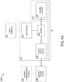
FIG. 1B is a block diagram illustrating a controller for the variable power water heater, in accordance with one or more embodiments of this disclosure; and -
FIG. 2 is a flow diagram illustrating a method for controlling a variable power water heater, in accordance with one or more embodiments of this disclosure. - Before explaining one or more embodiments of the disclosure in detail, it is to be understood that the embodiments are not limited in their application to the details of construction and the arrangement of the components or steps or methodologies set forth in the following description or illustrated in the drawings. In the following detailed description of embodiments, numerous specific details may be set forth in order to provide a more thorough understanding of the disclosure. However, it will be apparent to one of ordinary skill in the art having the benefit of the instant disclosure that the embodiments disclosed herein may be practiced without some of these specific details. In other instances, well-known features may not be described in detail to avoid unnecessarily complicating the instant disclosure.
- As used herein a letter following a reference numeral is intended to reference an embodiment of the feature or element that may be similar, but not necessarily identical, to a previously described element or feature bearing the same reference numeral (e.g., 1, 1a, 1b). Such shorthand notations are used for purposes of convenience only and should not be construed to limit the disclosure in any way unless expressly stated to the contrary.
- Further, unless expressly stated to the contrary, "or" refers to an inclusive or and not to an exclusive or. For example, a condition A or B is satisfied by anyone of the following: A is true (or present) and B is false (or not present), A is false (or not present) and B is true (or present), and both A and B are true (or present).
- In addition, use of "a" or "an" may be employed to describe elements and components of embodiments disclosed herein. This is done merely for convenience and "a" and "an" are intended to include "one" or "at least one," and the singular also includes the plural unless it is obvious that it is meant otherwise.
- Finally, as used herein any reference to "one embodiment" or "some embodiments" means that a particular element, feature, structure, or characteristic described in connection with the embodiment is included in at least one embodiment disclosed herein. The appearances of the phrase "in some embodiments" in various places in the specification are not necessarily all referring to the same embodiment, and embodiments may include one or more of the features expressly described or inherently present herein, or any combination of subcombination of two or more such features, along with any other features which may not necessarily be expressly described or inherently present in the instant disclosure.
- A variable power water heater is disclosed. Often, water heaters are designed with fixed hardware for powering their heating elements. This hardware may have fixed power requirements. Consequently, an entire water heater, or at least the hardware for powering its heating element, may need to be changed when the water heater is implemented in a facility (e.g., an aircraft or other passenger vehicle, a building, etc.) that does not meet the power requirements of the water heater. The variable power water heater disclosed herein is a software-controlled water heater that can adjust its duty cycle to meet selected power requirements or power budget of an aircraft or any other setting/facility in which the variable power water heater is installed
- The variable power water heater may be configured for use in a variety of settings or facilities, such as, but not limited to, an aircraft lavatory (e.g., for a faucet, shower, etc.), an aircraft galley (e.g., for a coffee maker, faucet, dishwasher, etc.), or any other vehicle or building facility. Although an aircraft environment is discussed throughout this disclosure, the variable power water heater and/or control system for the variable power water heater may be implemented in any other setting or facility. In this regard, the examples and embodiments provided herein are not intended as limitations of the present disclosure unless otherwise specified in the claims.
-
FIG. 1A is a block diagram illustrating an aircraft environment/system 100 that includes a variablepower water heater 101, in accordance with one or more embodiments of this disclosure. In some embodiments, the variablepower water heater 101 includes awater tank 104, aheating element 102, apower supply circuit 106, aswitch 110, and acontroller 112. In other embodiments, one or more of the components (e.g.,water tank 104,heating element 102,power supply circuit 106,switch 110, and/or controller 112) may be structurally separate from the variablepower water heater 101. For example, thepower supply circuit 106,switch 110, and/orcontroller 112 may be coupled to the variablepower water heater 101 via an external connection interface (e.g., an external port or connector). - The heating element (or elements) 102 may be disposed within or coupled to the
water tank 104. For example, in some embodiments, theheating element 102 may be disposed within thewater tank 104 such that theheating element 102 becomes at least partially submerged when thewater tank 104 is filled. In other embodiments, the heating element 102 (or another (e.g., second, third, etc.) heating element 102) may be coupled to a side or bottom portion of thewater tank 104. For example, theheating element 102 may be coupled or otherwise held in contact with an internal or external side or bottom surface of thewater tank 102. In other embodiments, the heating element 102 (or elements) may be configured to heat one or more tubes or pipes that flow the water. For example, the variablepower water heater 101 may be a tankless water heater and/or configured with an auxiliary heating system. In some embodiments, thewater tank 104 or heated tube/pipe may be continuously or periodically filled by portable water supplied from a main water tank of the aircraft. - The
power supply circuit 106 may be configured to generate a power signal for theheating element 102. In embodiments, the power supply circuit 106 (e.g., a power supply unit (PSU), or the like) is coupled to a power source. For example, thepower supply circuit 106 may be connected to anaircraft power system 108. In some embodiments, theaircraft power system 108 is configured to supply 115V, 400Hz aircraft power. In other embodiments, theaircraft power system 108 may be configured to provide aircraft power at other voltages (e.g., at any voltage in the range of 100-240V, etc.) or other frequencies (e.g., at any frequency in the range of 100-1000Hz, etc.). - The
switch 110 may be configured to couple thepower supply circuit 106 to theheating element 102. For example, theswitch 110 can be configured to connect thepower supply circuit 106 to theheating element 102 in a closed state and disconnect thepower supply circuit 106 from theheating element 102 in an open state. In some embodiments, theswitch 110 is part of thepower supply circuit 106. In other embodiments, theswitch 110 is a separate component disposed in between thepower supply circuit 106 and theheating element 102. Theswitch 110 may be a triac (also known as a bidirectional triode thyristor or bilateral triode thyristor) or any other electrical or electromechanical switch element that connects thepower supply circuit 106 to theheating element 102. - The
controller 112 may be configured to toggle theswitch 110 according to a pulse width modulation (PWM) scheme to control a duty cycle of the power signal transmitted from thepower supply circuit 106 to theheating element 102. In this manner, water in thewater tank 104 and/or heated tube/pipe can be heated by theheating element 102, and the power to theheating element 102 can be controlled by toggling theswitch 110 according to the PWM-driven duty cycle to achieve target power requirements for the aircraft. - As shown in
FIG. 1B , thecontroller 112 may include aprocessor 118,memory 120, and acommunication interface 122. Theprocessor 118 provides processing functionality for at least thecontroller 112 and can include any number of processors, micro-controllers, circuitry, field programmable gate array (FPGA) or other processing systems, and resident or external memory for storing data, executable code, and other information accessed or generated by thecontroller 112. Theprocessor 118 can execute one or more software programs embodied in a non-transitory computer readable medium (e.g., memory 120) that implement techniques described herein. Theprocessor 118 is not limited by the materials from which it is formed, or the processing mechanisms employed therein and, as such, can be implemented via semiconductor(s) and/or transistors (e.g., using electronic integrated circuit (IC) components), and so forth. - The
memory 120 can be an example of tangible, computer-readable storage medium that provides storage functionality to store various data and/or program code associated with operation of thecontroller 112/processor 118, such as software programs and/or code segments, or other data to instruct theprocessor 118, and possibly other components of thecontroller 112, to perform the functionality described herein. Thus, thememory 120 can store data, such as a program of instructions for operating thecontroller 112, including its components (e.g.,processor 118,communication interface 122, etc.), and so forth. It should be noted that while asingle memory 120 is described, a wide variety of types and combinations of memory (e.g., tangible, non-transitory memory) can be employed. Thememory 120 can be integral with theprocessor 118, can comprise stand-alone memory, or can be a combination of both. Some examples of thememory 120 can include removable and non-removable memory components, such as random-access memory (RAM), read-only memory (ROM), flash memory (e.g., a secure digital (SD) memory card, a mini-SD memory card, and/or a micro-SD memory card), solid-state drive (SSD) memory, magnetic memory, optical memory, universal serial bus (USB) memory devices, hard disk memory, external memory, and so forth. - The
communication interface 122 can be operatively configured to communicate with components of thecontroller 112. For example, thecommunication interface 122 can be configured to retrieve data from theprocessor 118 or other devices (e.g.,aircraft power system 108,aircraft communication system 114, a temperature sensor (e.g., for sensing water temperature),user interface 116, etc.), transmit data for storage in thememory 120, retrieve data from storage in thememory 120, and so forth. Thecommunication interface 122 can also be communicatively coupled with theprocessor 118 to facilitate data transfer between components of thecontroller 112 and theprocessor 118. It should be noted that while thecommunication interface 122 is described as a component of thecontroller 112, one or more components of thecommunication interface 122 can be implemented as external components communicatively coupled to thecontroller 112 via a wired and/or wireless connection. Thecontroller 112 can also include and/or connect to one or more input/output (I/O) devices (e.g.,user interface 116 or other human machine interface (HMI) devices) via thecommunication interface 122. In embodiments, thecommunication interface 122 may include a transmitter, receiver, transceiver, physical connection interface, or any combination thereof. - The
power supply circuit 106 may include fixed hardware, and the power to theheating element 102 may be varied by toggling theswitch 110 via thecontroller 112 to implement a selected PWM scheme. In other embodiments, thepower supply circuit 106 and thecontroller 112 may be integrated into a combined power supply andcontrol circuit 124. The power supply andcontrol circuit 124 may be configured to output a PWM power signal with a controlled duty cycle. In either case, thecontroller 112 may be configured to execute software to determine an identifier (e.g., power system identifier, aircraft type, etc.) or one or more power source characteristics (e.g., supported wattage) and control the duty cycle of the power signal to power theheating element 102 according to the power source characteristics/requirements of the aircraft. - In some embodiments, the
controller 112 is configured to detect an identifier and determine the PWM scheme based on the identifier. For example, thecontroller 112 may be configured to detect the identifier via an interface connection (e.g., identifier code sequence or programming detected via one or more connector pins) between thecontroller 112 and an aircraft communication system 114 (e.g., Controller Area Network (CAN) data bus, or the like) and/or theaircraft power system 108 itself. In another example, thecontroller 112 can be configured to receive the identifier in a data signal communicated via theaircraft communication system 114 or viauser interface 116. - The
controller 112 may be configured to determine the PWM scheme based on the identifier by comparing the identifier with a lookup table including a plurality of identifiers and a plurality of PWM schemes corresponding to the plurality of identifiers. For example, various aircraft types and/or power systems may be stored in a listing with corresponding PWM schemes or duty cycles for achieving the target power requirements for the aircraft. - In some embodiments, the
controller 112 is configured to detect one or more power source characteristics and determine the PWM scheme based on the one or more power source characteristics. For example, thecontroller 112 may be configured to detect the one or more power source characteristics via an interface connection (e.g., code sequence or programming detected via one or more connector pins) between thecontroller 112 and an aircraft communication system 114 (e.g., Controller Area Network (CAN) data bus, or the like) and/or theaircraft power system 108 itself. In another example, thecontroller 112 can be configured to receive the one or more power source characteristics in a data signal communicated via theaircraft communication system 114 or viauser interface 116. - The
controller 112 may be configured to determine the PWM scheme by calculating the duty cycle of the power signal based on the one or more power source characteristics. For example, thecontroller 112 can be configured to calculate a duty cycle based on the one or more detected power source characteristics (e.g., based on supported wattage) for the aircraft. Thecontroller 112 can be further configured to determine the PWM scheme for achieving the calculated duty cycle. Alternatively, thecontroller 112 may be configured to determine the PWM scheme based on the one or more power source characteristics by comparing the one or more power source characteristics with a lookup table including a plurality of power source characteristics and a plurality of PWM schemes corresponding to the different power source characteristics. For example, various power source characteristics (e.g., values or ranges of power requirements, supported wattages, etc.) may be stored in a listing with corresponding PWM schemes or duty cycles for achieving the target power requirements for the aircraft. - When the
controller 112 is unable to detect an identifier and/or power source characteristics for the aircraft, or when there are no lookup table entries corresponding to the detected identifier and/or power source characteristics, thecontroller 112 may be configured to set the PWM scheme to a default PWM scheme. For example, in such cases, thecontroller 112 may be configured to set the PWM scheme to a PWM scheme associated with a default duty cycle (e.g., 70% duty cycle, 60% duty cycle, 50% duty cycle, or less). - In some embodiments, the
controller 112 is communicatively coupled to auser interface 116. Thecontroller 112 may be configured to receive a user-input temperature setting, duty cycle, identifier, power source characteristics, and/or power requirement via theuser interface 116. In embodiments, theuser interface 116 may include, but is not limited to, a display, a touchscreen display, touch panel, touchpad, keyboard, keypad, knob, buttons, switches, or any combination thereof. In some embodiments, theuser interface 116 comprises a personal electronic device (e.g., mobile device, personal computer, etc.) that is communicatively coupled to thecontroller 112 via theaircraft communication system 114. In some embodiments, theuser interface 116 can be used to override the controller programming, for example, to manually set the duty cycle or target power level/requirement. -
FIG. 2 illustrates one or more embodiments of amethod 200 for controlling the variablepower water heater 101 described herein. In general, any steps or operations of disclosed processes (e.g., method 200) may be performed in an arbitrary order, unless otherwise provided in the claims. - At
step 202, themethod 200 includes generating a power signal for aheating element 102. For example, thepower supply circuit 106 may be configured to generate a power signal for theheating element 102. - At
step 204, themethod 200 includes detecting an identifier or one or more power source characteristics. For example, thecontroller 112 may be configured to detect the identifier or the one or more power source characteristics via an interface connection between thecontroller 112 and theaircraft communication system 114 and/or theaircraft power system 108. In another example, thecontroller 112 can be configured to receive the identifier or the one or more power source characteristics in a data signal communicated via theaircraft communication system 114 or viauser interface 116. - At
step 206, themethod 200 includes determining a PWM scheme based on the identifier or the one or more power source characteristics. For example, thecontroller 112 may be configured to determine the PWM scheme based on the identifier by comparing the identifier with a lookup table including a plurality of identifiers and a plurality of PWM schemes corresponding to the plurality of identifiers. In another example, thecontroller 112 can be configured to calculate a duty cycle based on the one or more detected power source characteristics and further configured to determine the PWM scheme for achieving the calculated duty cycle. Alternatively, thecontroller 112 may be configured to determine the PWM scheme based on the one or more power source characteristics by comparing the one or more power source characteristics with a lookup table including a plurality of power source characteristics and a plurality of PWM schemes corresponding to the different power source characteristics. - At
step 208, themethod 200 includes toggling a switch that delivers the power signal to the heating element according to the PWM scheme to control a duty cycle of the power signal. For example, thecontroller 112 may be configured to toggle theswitch 110 according to the selected, calculated, or otherwise determined PWM scheme to control a duty cycle of the power signal transmitted from thepower supply circuit 106 to theheating element 102. In this manner, water in thewater tank 104 and/or heated tube/pipe can be heated by theheating element 102, and the power to theheating element 102 can be controlled by toggling theswitch 110 according to the PWM-driven duty cycle to achieve target power requirements for the aircraft. - The
method 200 may further include any step or operation implied or required by one or more embodiments of the variablepower water heater 101/system 100 described herein. The variablepower water heater 101/system 100 can also include any additional component or functionality expressed or implied by one or more embodiments of themethod 200. - It is to be understood that implementations of the methods disclosed herein may include one or more of the steps described herein. Further, such steps may be carried out in any desired order and two or more of the steps may be carried out simultaneously with one another. Two or more of the steps disclosed herein may be combined in a single step, and in some implementations, one or more of the steps may be carried out as two or more sub-steps. Further, other steps or sub-steps may be carried in addition to, or as substitutes to one or more of the steps disclosed herein.
- Although inventive concepts have been described with reference to the embodiments illustrated in the attached drawing figures, equivalents may be employed and substitutions made herein without departing from the scope of the claims. Components illustrated and described herein are merely examples of a system/device and components that may be used to implement embodiments of the inventive concepts and may be replaced with other devices and components without departing from the scope of the claims. Furthermore, any dimensions, degrees, and/or numerical ranges provided herein are to be understood as non-limiting examples unless otherwise specified in the claims.
Claims (12)
- A control system for a variable power water heater, comprising:a power supply circuit (106) configured to generate a power signal for a heating element;a switch (110) configured to couple the power supply circuit to the heating element; anda controller (112) configured to toggle the switch according to a pulse width modulation scheme to control a duty cycle of the power signal transmitted from the power supply circuit to the heating element.
- The control system of claim 1, wherein the switch comprises a triac.
- The control system of claim 1 or 2, wherein the controller is further configured to:detect an identifier; anddetermine the pulse width modulation scheme based on the identifier.
- The control system of claim 3, wherein the controller is configured to detect the identifier via an interface connection between the controller and at least one of an aircraft communication system or an aircraft power system.
- The control system of claim 3, wherein the controller is configured to determine the pulse width modulation scheme based on the identifier by comparing the identifier with a lookup table including a plurality of identifiers and a plurality of pulse width modulation schemes corresponding to the plurality of identifiers.
- The control system of claim 3, wherein the controller is further configured to set the pulse width modulation scheme to a default pulse width modulation scheme when the controller is unable to detect the identifier.
- The control system of any preceding claim, wherein the controller is further configured to:detect one or more power source characteristics; anddetermine the pulse width modulation scheme based on the one or more power source characteristics.
- The control system of claim 7, wherein the controller is configured to detect the one or more power source characteristics via an interface connection between the controller and at least one of an aircraft communication system or an aircraft power system.
- The control system of claim 7, wherein the controller is configured to determine the pulse width modulation scheme by calculating the duty cycle of the power signal based on the one or more power source characteristics.
- A variable power water heater, comprising:a water tank;a heating element disposed within or coupled to the water tank and the control system of any preceding claim.
- The variable power water heater of claim 10, wherein the power supply circuit and the controller are integrated into a combined power supply and control circuit.
- A method of controlling a variable power water heater, comprising:generating a power signal for a heating element;detecting an identifier or one or more power source characteristics;determining a pulse width modulation scheme based on the identifier or the one or more power source characteristics; andtoggling a switch that delivers the power signal to the heating element according to the pulse width modulation scheme to control a duty cycle of the power signal.
Applications Claiming Priority (1)
| Application Number | Priority Date | Filing Date | Title |
|---|---|---|---|
| US16/277,796 US11215381B2 (en) | 2019-02-15 | 2019-02-15 | Variable power water heater |
Publications (2)
| Publication Number | Publication Date |
|---|---|
| EP3697173A1 true EP3697173A1 (en) | 2020-08-19 |
| EP3697173B1 EP3697173B1 (en) | 2021-10-13 |
Family
ID=68916169
Family Applications (1)
| Application Number | Title | Priority Date | Filing Date |
|---|---|---|---|
| EP19215672.7A Active EP3697173B1 (en) | 2019-02-15 | 2019-12-12 | Variable power water heater, control system therefor and control method thereof |
Country Status (3)
| Country | Link |
|---|---|
| US (1) | US11215381B2 (en) |
| EP (1) | EP3697173B1 (en) |
| CN (1) | CN111578522B (en) |
Families Citing this family (1)
| Publication number | Priority date | Publication date | Assignee | Title |
|---|---|---|---|---|
| US20210169681A1 (en) * | 2019-12-05 | 2021-06-10 | Robert Dempsey | Controlled temperature water bottle |
Citations (4)
| Publication number | Priority date | Publication date | Assignee | Title |
|---|---|---|---|---|
| JP2002295907A (en) * | 2001-03-29 | 2002-10-09 | Toto Ltd | Sanitary washing equipment |
| US20070272678A1 (en) * | 2003-11-26 | 2007-11-29 | Yitzhak Meyuchas | Apparatus and Method of Computer Component Heating |
| EP2375854A1 (en) * | 2010-04-06 | 2011-10-12 | Inergy Automotive Systems Research (Société Anonyme) | Heater for a vehicular fluid tank, motor vehicle comprising same, and method for heating a vehicular fluid tank |
| JP2017058040A (en) * | 2015-09-14 | 2017-03-23 | 株式会社バイタル | Vehicular hot water system |
Family Cites Families (10)
| Publication number | Priority date | Publication date | Assignee | Title |
|---|---|---|---|---|
| US4357524A (en) | 1980-01-29 | 1982-11-02 | Westinghouse Electric Corp. | Electrical heater controller for aircraft window heat control |
| AUPN560795A0 (en) | 1995-09-25 | 1995-10-19 | Stokes (Australasia) Limited | Heating element assembly |
| US6633726B2 (en) * | 1999-07-27 | 2003-10-14 | Kenneth A. Bradenbaugh | Method of controlling the temperature of water in a water heater |
| US6841761B1 (en) * | 2003-04-02 | 2005-01-11 | Whirlpool Corporation | Nominal voltage identification system for electric resistance |
| US20060263073A1 (en) * | 2005-05-23 | 2006-11-23 | Jcs/Thg,Llp. | Multi-power multi-stage electric heater |
| US9419520B2 (en) * | 2012-02-16 | 2016-08-16 | Abominable Labs, Llc | Battery compensation system using PWM |
| US20150035509A1 (en) * | 2013-07-31 | 2015-02-05 | Semiconductor Energy Laboratory Co., Ltd. | Control circuit and dc-dc converter |
| US20150144300A1 (en) * | 2013-11-22 | 2015-05-28 | Thermo Fisher Scientific (Asheville) Llc | Recirculating Bath With Global Voltage Compatibility |
| ITUB20153569A1 (en) * | 2015-09-11 | 2017-03-11 | De Longhi Appliances Srl | ELECTRIC COOKING AND / OR HEATING OF FOOD APPLIANCES |
| AU2016250449A1 (en) * | 2016-10-28 | 2018-05-17 | Rheem Australia Pty Limited | A system, apparatus and method for efficient use of solar photovoltaic energy |
-
2019
- 2019-02-15 US US16/277,796 patent/US11215381B2/en active Active
- 2019-12-12 EP EP19215672.7A patent/EP3697173B1/en active Active
- 2019-12-13 CN CN201911278583.3A patent/CN111578522B/en active Active
Patent Citations (4)
| Publication number | Priority date | Publication date | Assignee | Title |
|---|---|---|---|---|
| JP2002295907A (en) * | 2001-03-29 | 2002-10-09 | Toto Ltd | Sanitary washing equipment |
| US20070272678A1 (en) * | 2003-11-26 | 2007-11-29 | Yitzhak Meyuchas | Apparatus and Method of Computer Component Heating |
| EP2375854A1 (en) * | 2010-04-06 | 2011-10-12 | Inergy Automotive Systems Research (Société Anonyme) | Heater for a vehicular fluid tank, motor vehicle comprising same, and method for heating a vehicular fluid tank |
| JP2017058040A (en) * | 2015-09-14 | 2017-03-23 | 株式会社バイタル | Vehicular hot water system |
Also Published As
| Publication number | Publication date |
|---|---|
| US20200263904A1 (en) | 2020-08-20 |
| CN111578522A (en) | 2020-08-25 |
| CN111578522B (en) | 2022-08-16 |
| EP3697173B1 (en) | 2021-10-13 |
| US11215381B2 (en) | 2022-01-04 |
Similar Documents
| Publication | Publication Date | Title |
|---|---|---|
| CN103263224B (en) | Electric heating device, electric cooker and wireless temperature control method | |
| US9752784B2 (en) | Heating element control circuit | |
| AU2017202218A1 (en) | Fluid heating system and instant fluid heating device | |
| US9777927B2 (en) | Double oven preheat boost using cooking chamber lockout | |
| CN102389254A (en) | Temperature control method of electric heating kitchenware | |
| CN104214957B (en) | Water heater with wireless temperature controller | |
| US10274226B2 (en) | Electronic control system for electric water heater | |
| KR20170023868A (en) | Heat pump hot water machine control method and system | |
| CN108617043A (en) | The control method and control device and cooking appliance of cooking appliance | |
| CN103983019A (en) | Intelligent water mixing control device, intelligent water mixing control device method and water heater | |
| CN107003013B (en) | Heater control method of water heating pad and water heating pad suitable for heater control method | |
| CN110025228B (en) | Electric oven and temperature control method thereof | |
| US11215381B2 (en) | Variable power water heater | |
| CN104266239A (en) | Control method and system of microwave oven | |
| CN104287612B (en) | Steam roaster | |
| US20190293298A1 (en) | Cooktop appliance | |
| CN104110886B (en) | Electric heater and its control method | |
| US12321182B2 (en) | Cooktop appliance with variable closed-loop controls | |
| CN104287613A (en) | Steam oven | |
| CN203893438U (en) | Electric water heater | |
| JP2007280941A (en) | Heating cooker | |
| US20250374392A1 (en) | Heat molding mode for an oven appliance | |
| CN104287639B (en) | Steam roaster | |
| CN106247643B (en) | A kind of power control system of solar water heater | |
| CN118935744A (en) | Water heater temperature adjustment method, device and water heater |
Legal Events
| Date | Code | Title | Description |
|---|---|---|---|
| PUAI | Public reference made under article 153(3) epc to a published international application that has entered the european phase |
Free format text: ORIGINAL CODE: 0009012 |
|
| STAA | Information on the status of an ep patent application or granted ep patent |
Free format text: STATUS: THE APPLICATION HAS BEEN PUBLISHED |
|
| AK | Designated contracting states |
Kind code of ref document: A1 Designated state(s): AL AT BE BG CH CY CZ DE DK EE ES FI FR GB GR HR HU IE IS IT LI LT LU LV MC MK MT NL NO PL PT RO RS SE SI SK SM TR |
|
| AX | Request for extension of the european patent |
Extension state: BA ME |
|
| RIN1 | Information on inventor provided before grant (corrected) |
Inventor name: BUNIAK, BRADLEY J. Inventor name: STEENSTRA TOUSSAINT, TYSON J. Inventor name: HASIRUMANE, AVINASH SRIKANTEGOWDA |
|
| STAA | Information on the status of an ep patent application or granted ep patent |
Free format text: STATUS: REQUEST FOR EXAMINATION WAS MADE |
|
| 17P | Request for examination filed |
Effective date: 20210219 |
|
| RBV | Designated contracting states (corrected) |
Designated state(s): AL AT BE BG CH CY CZ DE DK EE ES FI FR GB GR HR HU IE IS IT LI LT LU LV MC MK MT NL NO PL PT RO RS SE SI SK SM TR |
|
| GRAP | Despatch of communication of intention to grant a patent |
Free format text: ORIGINAL CODE: EPIDOSNIGR1 |
|
| STAA | Information on the status of an ep patent application or granted ep patent |
Free format text: STATUS: GRANT OF PATENT IS INTENDED |
|
| RIC1 | Information provided on ipc code assigned before grant |
Ipc: H05B 1/02 20060101AFI20210329BHEP Ipc: F24H 1/18 20060101ALI20210329BHEP Ipc: G05B 11/28 20060101ALI20210329BHEP Ipc: G05D 23/19 20060101ALI20210329BHEP |
|
| INTG | Intention to grant announced |
Effective date: 20210429 |
|
| RAP3 | Party data changed (applicant data changed or rights of an application transferred) |
Owner name: B/E AEROSPACE, INC. |
|
| GRAS | Grant fee paid |
Free format text: ORIGINAL CODE: EPIDOSNIGR3 |
|
| GRAA | (expected) grant |
Free format text: ORIGINAL CODE: 0009210 |
|
| STAA | Information on the status of an ep patent application or granted ep patent |
Free format text: STATUS: THE PATENT HAS BEEN GRANTED |
|
| AK | Designated contracting states |
Kind code of ref document: B1 Designated state(s): AL AT BE BG CH CY CZ DE DK EE ES FI FR GB GR HR HU IE IS IT LI LT LU LV MC MK MT NL NO PL PT RO RS SE SI SK SM TR |
|
| REG | Reference to a national code |
Ref country code: GB Ref legal event code: FG4D |
|
| REG | Reference to a national code |
Ref country code: CH Ref legal event code: EP |
|
| REG | Reference to a national code |
Ref country code: DE Ref legal event code: R096 Ref document number: 602019008330 Country of ref document: DE |
|
| REG | Reference to a national code |
Ref country code: IE Ref legal event code: FG4D |
|
| REG | Reference to a national code |
Ref country code: AT Ref legal event code: REF Ref document number: 1439116 Country of ref document: AT Kind code of ref document: T Effective date: 20211115 |
|
| REG | Reference to a national code |
Ref country code: LT Ref legal event code: MG9D |
|
| REG | Reference to a national code |
Ref country code: NL Ref legal event code: MP Effective date: 20211013 |
|
| REG | Reference to a national code |
Ref country code: AT Ref legal event code: MK05 Ref document number: 1439116 Country of ref document: AT Kind code of ref document: T Effective date: 20211013 |
|
| PG25 | Lapsed in a contracting state [announced via postgrant information from national office to epo] |
Ref country code: RS Free format text: LAPSE BECAUSE OF FAILURE TO SUBMIT A TRANSLATION OF THE DESCRIPTION OR TO PAY THE FEE WITHIN THE PRESCRIBED TIME-LIMIT Effective date: 20211013 Ref country code: LT Free format text: LAPSE BECAUSE OF FAILURE TO SUBMIT A TRANSLATION OF THE DESCRIPTION OR TO PAY THE FEE WITHIN THE PRESCRIBED TIME-LIMIT Effective date: 20211013 Ref country code: FI Free format text: LAPSE BECAUSE OF FAILURE TO SUBMIT A TRANSLATION OF THE DESCRIPTION OR TO PAY THE FEE WITHIN THE PRESCRIBED TIME-LIMIT Effective date: 20211013 Ref country code: BG Free format text: LAPSE BECAUSE OF FAILURE TO SUBMIT A TRANSLATION OF THE DESCRIPTION OR TO PAY THE FEE WITHIN THE PRESCRIBED TIME-LIMIT Effective date: 20220113 Ref country code: AT Free format text: LAPSE BECAUSE OF FAILURE TO SUBMIT A TRANSLATION OF THE DESCRIPTION OR TO PAY THE FEE WITHIN THE PRESCRIBED TIME-LIMIT Effective date: 20211013 |
|
| PG25 | Lapsed in a contracting state [announced via postgrant information from national office to epo] |
Ref country code: IS Free format text: LAPSE BECAUSE OF FAILURE TO SUBMIT A TRANSLATION OF THE DESCRIPTION OR TO PAY THE FEE WITHIN THE PRESCRIBED TIME-LIMIT Effective date: 20220213 Ref country code: SE Free format text: LAPSE BECAUSE OF FAILURE TO SUBMIT A TRANSLATION OF THE DESCRIPTION OR TO PAY THE FEE WITHIN THE PRESCRIBED TIME-LIMIT Effective date: 20211013 Ref country code: PT Free format text: LAPSE BECAUSE OF FAILURE TO SUBMIT A TRANSLATION OF THE DESCRIPTION OR TO PAY THE FEE WITHIN THE PRESCRIBED TIME-LIMIT Effective date: 20220214 Ref country code: PL Free format text: LAPSE BECAUSE OF FAILURE TO SUBMIT A TRANSLATION OF THE DESCRIPTION OR TO PAY THE FEE WITHIN THE PRESCRIBED TIME-LIMIT Effective date: 20211013 Ref country code: NO Free format text: LAPSE BECAUSE OF FAILURE TO SUBMIT A TRANSLATION OF THE DESCRIPTION OR TO PAY THE FEE WITHIN THE PRESCRIBED TIME-LIMIT Effective date: 20220113 Ref country code: NL Free format text: LAPSE BECAUSE OF FAILURE TO SUBMIT A TRANSLATION OF THE DESCRIPTION OR TO PAY THE FEE WITHIN THE PRESCRIBED TIME-LIMIT Effective date: 20211013 Ref country code: LV Free format text: LAPSE BECAUSE OF FAILURE TO SUBMIT A TRANSLATION OF THE DESCRIPTION OR TO PAY THE FEE WITHIN THE PRESCRIBED TIME-LIMIT Effective date: 20211013 Ref country code: HR Free format text: LAPSE BECAUSE OF FAILURE TO SUBMIT A TRANSLATION OF THE DESCRIPTION OR TO PAY THE FEE WITHIN THE PRESCRIBED TIME-LIMIT Effective date: 20211013 Ref country code: GR Free format text: LAPSE BECAUSE OF FAILURE TO SUBMIT A TRANSLATION OF THE DESCRIPTION OR TO PAY THE FEE WITHIN THE PRESCRIBED TIME-LIMIT Effective date: 20220114 Ref country code: ES Free format text: LAPSE BECAUSE OF FAILURE TO SUBMIT A TRANSLATION OF THE DESCRIPTION OR TO PAY THE FEE WITHIN THE PRESCRIBED TIME-LIMIT Effective date: 20211013 |
|
| REG | Reference to a national code |
Ref country code: DE Ref legal event code: R097 Ref document number: 602019008330 Country of ref document: DE |
|
| PG25 | Lapsed in a contracting state [announced via postgrant information from national office to epo] |
Ref country code: SM Free format text: LAPSE BECAUSE OF FAILURE TO SUBMIT A TRANSLATION OF THE DESCRIPTION OR TO PAY THE FEE WITHIN THE PRESCRIBED TIME-LIMIT Effective date: 20211013 Ref country code: SK Free format text: LAPSE BECAUSE OF FAILURE TO SUBMIT A TRANSLATION OF THE DESCRIPTION OR TO PAY THE FEE WITHIN THE PRESCRIBED TIME-LIMIT Effective date: 20211013 Ref country code: RO Free format text: LAPSE BECAUSE OF FAILURE TO SUBMIT A TRANSLATION OF THE DESCRIPTION OR TO PAY THE FEE WITHIN THE PRESCRIBED TIME-LIMIT Effective date: 20211013 Ref country code: MC Free format text: LAPSE BECAUSE OF FAILURE TO SUBMIT A TRANSLATION OF THE DESCRIPTION OR TO PAY THE FEE WITHIN THE PRESCRIBED TIME-LIMIT Effective date: 20211013 Ref country code: EE Free format text: LAPSE BECAUSE OF FAILURE TO SUBMIT A TRANSLATION OF THE DESCRIPTION OR TO PAY THE FEE WITHIN THE PRESCRIBED TIME-LIMIT Effective date: 20211013 Ref country code: DK Free format text: LAPSE BECAUSE OF FAILURE TO SUBMIT A TRANSLATION OF THE DESCRIPTION OR TO PAY THE FEE WITHIN THE PRESCRIBED TIME-LIMIT Effective date: 20211013 Ref country code: CZ Free format text: LAPSE BECAUSE OF FAILURE TO SUBMIT A TRANSLATION OF THE DESCRIPTION OR TO PAY THE FEE WITHIN THE PRESCRIBED TIME-LIMIT Effective date: 20211013 |
|
| PLBE | No opposition filed within time limit |
Free format text: ORIGINAL CODE: 0009261 |
|
| STAA | Information on the status of an ep patent application or granted ep patent |
Free format text: STATUS: NO OPPOSITION FILED WITHIN TIME LIMIT |
|
| 26N | No opposition filed |
Effective date: 20220714 |
|
| REG | Reference to a national code |
Ref country code: BE Ref legal event code: MM Effective date: 20211231 |
|
| PG25 | Lapsed in a contracting state [announced via postgrant information from national office to epo] |
Ref country code: LU Free format text: LAPSE BECAUSE OF NON-PAYMENT OF DUE FEES Effective date: 20211212 Ref country code: IE Free format text: LAPSE BECAUSE OF NON-PAYMENT OF DUE FEES Effective date: 20211212 Ref country code: AL Free format text: LAPSE BECAUSE OF FAILURE TO SUBMIT A TRANSLATION OF THE DESCRIPTION OR TO PAY THE FEE WITHIN THE PRESCRIBED TIME-LIMIT Effective date: 20211013 |
|
| PG25 | Lapsed in a contracting state [announced via postgrant information from national office to epo] |
Ref country code: SI Free format text: LAPSE BECAUSE OF FAILURE TO SUBMIT A TRANSLATION OF THE DESCRIPTION OR TO PAY THE FEE WITHIN THE PRESCRIBED TIME-LIMIT Effective date: 20211013 Ref country code: BE Free format text: LAPSE BECAUSE OF NON-PAYMENT OF DUE FEES Effective date: 20211231 |
|
| PG25 | Lapsed in a contracting state [announced via postgrant information from national office to epo] |
Ref country code: IT Free format text: LAPSE BECAUSE OF FAILURE TO SUBMIT A TRANSLATION OF THE DESCRIPTION OR TO PAY THE FEE WITHIN THE PRESCRIBED TIME-LIMIT Effective date: 20211013 |
|
| PG25 | Lapsed in a contracting state [announced via postgrant information from national office to epo] |
Ref country code: CY Free format text: LAPSE BECAUSE OF FAILURE TO SUBMIT A TRANSLATION OF THE DESCRIPTION OR TO PAY THE FEE WITHIN THE PRESCRIBED TIME-LIMIT Effective date: 20211013 |
|
| PG25 | Lapsed in a contracting state [announced via postgrant information from national office to epo] |
Ref country code: HU Free format text: LAPSE BECAUSE OF FAILURE TO SUBMIT A TRANSLATION OF THE DESCRIPTION OR TO PAY THE FEE WITHIN THE PRESCRIBED TIME-LIMIT; INVALID AB INITIO Effective date: 20191212 |
|
| REG | Reference to a national code |
Ref country code: CH Ref legal event code: PL |
|
| PG25 | Lapsed in a contracting state [announced via postgrant information from national office to epo] |
Ref country code: LI Free format text: LAPSE BECAUSE OF NON-PAYMENT OF DUE FEES Effective date: 20221231 Ref country code: CH Free format text: LAPSE BECAUSE OF NON-PAYMENT OF DUE FEES Effective date: 20221231 |
|
| PG25 | Lapsed in a contracting state [announced via postgrant information from national office to epo] |
Ref country code: MK Free format text: LAPSE BECAUSE OF FAILURE TO SUBMIT A TRANSLATION OF THE DESCRIPTION OR TO PAY THE FEE WITHIN THE PRESCRIBED TIME-LIMIT Effective date: 20211013 |
|
| PG25 | Lapsed in a contracting state [announced via postgrant information from national office to epo] |
Ref country code: TR Free format text: LAPSE BECAUSE OF FAILURE TO SUBMIT A TRANSLATION OF THE DESCRIPTION OR TO PAY THE FEE WITHIN THE PRESCRIBED TIME-LIMIT Effective date: 20211013 |
|
| PG25 | Lapsed in a contracting state [announced via postgrant information from national office to epo] |
Ref country code: MT Free format text: LAPSE BECAUSE OF FAILURE TO SUBMIT A TRANSLATION OF THE DESCRIPTION OR TO PAY THE FEE WITHIN THE PRESCRIBED TIME-LIMIT Effective date: 20211013 |
|
| PGFP | Annual fee paid to national office [announced via postgrant information from national office to epo] |
Ref country code: DE Payment date: 20251126 Year of fee payment: 7 |
|
| PGFP | Annual fee paid to national office [announced via postgrant information from national office to epo] |
Ref country code: GB Payment date: 20251119 Year of fee payment: 7 |
|
| PGFP | Annual fee paid to national office [announced via postgrant information from national office to epo] |
Ref country code: FR Payment date: 20251119 Year of fee payment: 7 |
|
| P01 | Opt-out of the competence of the unified patent court (upc) registered |
Free format text: CASE NUMBER: UPC_APP_0018912_3697173/2025 Effective date: 20251222 |