EP3696943A1 - Wireless power transmission system - Google Patents
Wireless power transmission system Download PDFInfo
- Publication number
- EP3696943A1 EP3696943A1 EP18865972.6A EP18865972A EP3696943A1 EP 3696943 A1 EP3696943 A1 EP 3696943A1 EP 18865972 A EP18865972 A EP 18865972A EP 3696943 A1 EP3696943 A1 EP 3696943A1
- Authority
- EP
- European Patent Office
- Prior art keywords
- power transmission
- power
- hmd
- power receiving
- coil
- Prior art date
- Legal status (The legal status is an assumption and is not a legal conclusion. Google has not performed a legal analysis and makes no representation as to the accuracy of the status listed.)
- Withdrawn
Links
Images



Classifications
-
- H—ELECTRICITY
- H02—GENERATION; CONVERSION OR DISTRIBUTION OF ELECTRIC POWER
- H02J—ELECTRIC POWER NETWORKS; CIRCUIT ARRANGEMENTS OR SYSTEMS FOR SUPPLYING OR DISTRIBUTING ELECTRIC POWER; SYSTEMS FOR STORING ELECTRIC ENERGY
- H02J50/00—Circuit arrangements or systems for wireless supply or distribution of electric power
- H02J50/40—Circuit arrangements or systems for wireless supply or distribution of electric power using two or more transmitting or receiving devices
-
- H—ELECTRICITY
- H02—GENERATION; CONVERSION OR DISTRIBUTION OF ELECTRIC POWER
- H02J—ELECTRIC POWER NETWORKS; CIRCUIT ARRANGEMENTS OR SYSTEMS FOR SUPPLYING OR DISTRIBUTING ELECTRIC POWER; SYSTEMS FOR STORING ELECTRIC ENERGY
- H02J50/00—Circuit arrangements or systems for wireless supply or distribution of electric power
- H02J50/10—Circuit arrangements or systems for wireless supply or distribution of electric power using inductive coupling
-
- H—ELECTRICITY
- H02—GENERATION; CONVERSION OR DISTRIBUTION OF ELECTRIC POWER
- H02J—ELECTRIC POWER NETWORKS; CIRCUIT ARRANGEMENTS OR SYSTEMS FOR SUPPLYING OR DISTRIBUTING ELECTRIC POWER; SYSTEMS FOR STORING ELECTRIC ENERGY
- H02J50/00—Circuit arrangements or systems for wireless supply or distribution of electric power
- H02J50/10—Circuit arrangements or systems for wireless supply or distribution of electric power using inductive coupling
- H02J50/12—Circuit arrangements or systems for wireless supply or distribution of electric power using inductive coupling of the resonant type
-
- H—ELECTRICITY
- H02—GENERATION; CONVERSION OR DISTRIBUTION OF ELECTRIC POWER
- H02J—ELECTRIC POWER NETWORKS; CIRCUIT ARRANGEMENTS OR SYSTEMS FOR SUPPLYING OR DISTRIBUTING ELECTRIC POWER; SYSTEMS FOR STORING ELECTRIC ENERGY
- H02J50/00—Circuit arrangements or systems for wireless supply or distribution of electric power
- H02J50/90—Circuit arrangements or systems for wireless supply or distribution of electric power involving detection or optimisation of position, e.g. alignment
-
- H—ELECTRICITY
- H02—GENERATION; CONVERSION OR DISTRIBUTION OF ELECTRIC POWER
- H02J—ELECTRIC POWER NETWORKS; CIRCUIT ARRANGEMENTS OR SYSTEMS FOR SUPPLYING OR DISTRIBUTING ELECTRIC POWER; SYSTEMS FOR STORING ELECTRIC ENERGY
- H02J7/00—Circuit arrangements for charging or discharging batteries or for supplying loads from batteries
-
- H—ELECTRICITY
- H02—GENERATION; CONVERSION OR DISTRIBUTION OF ELECTRIC POWER
- H02J—ELECTRIC POWER NETWORKS; CIRCUIT ARRANGEMENTS OR SYSTEMS FOR SUPPLYING OR DISTRIBUTING ELECTRIC POWER; SYSTEMS FOR STORING ELECTRIC ENERGY
- H02J7/00—Circuit arrangements for charging or discharging batteries or for supplying loads from batteries
- H02J7/02—Circuit arrangements for charging or discharging batteries or for supplying loads from batteries for charging batteries from AC mains by converters
Definitions
- the present invention relates to a wireless power transmission system.
- a wireless power transmission system in which an electric power is wirelessly transmitted from a power transmission device to a power receiving object by using wireless power transmission such as electromagnetic induction-type and magnetic field resonance-type.
- the power transmission device includes a power transmission coil that generates the magnetic field
- the power receiving object includes a power receiving coil that receives the electric power by the magnetic field generated by the power transmission coil.
- the wireless power transmission system is used for various industrial products, and for example, a power receiving and supplying system in which the power receiving object is a hearing aid, and the power transmission device is a battery charger has been proposed (ref: for example, Patent Document 1).
- the battery charger includes a housing cup having a housing space that is capable of housing the hearing aid, and a plurality of power transmission coils disposed so as to generate a magnetic field in the entire housing space.
- the electric power is transmitted from the power transmission coil to the power receiving coil in a state where the hearing aid is housed in the housing space of the housing cup regardless of the direction and the position of the hearing aid.
- Patent Document 1 Japanese Unexamined Patent Publication No. 2017-135831
- the present invention provides a wireless power transmission system that is capable of achieving a reduction in electric power consumption.
- the present invention [1] includes a wireless power transmission system including a power transmission device including a plurality of power transmission portions, and a power receiving object including a power receiving portion capable of receiving an electric power wirelessly transmitted from the power transmission portion, wherein of the plurality of power transmission portions, a specific power transmission portion transmits the electric power to the power receiving portion.
- the specific power transmission portion transmits the electric power to the power receiving portion, so that a reduction in electric power consumption can be achieved compared to a case where all of the power transmission portions are operated at the time of transmission of the electric power.
- the present invention [2] includes the wireless power transmission system described in the above-described [1] further including a positioning portion positioning the placed power receiving object, wherein the power receiving object is capable of receiving an electric power in a state of being positioned by the positioning portion.
- the power receiving object is positioned by the positioning portion, so that the power receiving portion that is positioned can efficiently receive the electric power from the specific power transmission portion, so that improvement of transmission efficiency of the electric power can be achieved.
- the present invention [3] includes the wireless power transmission system described in the above-described [2], wherein the power transmission device further includes a wall portion extending in a vertical direction and provided with at least one of the plurality of power transmission portions, and the wall portion also functions as the positioning portion.
- At least one of the plurality of power transmission portions is provided in the wall portion, and the wall portion functions as the positioning portion, so that the power transmission portion can surely transmit the electric power to the power receiving portion in a state where the power receiving object is positioned by the wall portion.
- the improvement of the transmission efficiency of the electric power can be surely achieved.
- the power receiving portion In various power receiving objects, there is a limit in space where the power receiving portion can be disposed. Thus, when the power transmission portion is provided on the surface on which the power receiving object is placed, there may be a case where the power receiving portion cannot be disposed in a preferable position with respect to the power transmission portion at the time of placement of the power receiving object, so that the transmission efficiency of the electric power is reduced.
- the power transmission portion is provided in the wall portion, so that even in the above-described case, there may be a case where the power receiving portion can be disposed in a preferable position with respect to the power transmission portion at the time of the placement of the power receiving object.
- the present invention [4] includes the wireless power transmission system described in the above-described [3], wherein the power transmission device further includes a placement portion enabling placement of the power receiving object, and the wall portion is integrally provided with the placement portion.
- the wall portion is integrally provided with the placement portion enabling the placement of the power receiving object, so that a placement posture of the power receiving object can be set.
- the power transmission portion can further more surely transmit the electric power to the power receiving portion in a state where the power receiving object is positioned by the wall portion, and the improvement of the transmission efficiency of the electric power can be further more surely achieved.
- the present invention [5] includes the wireless power transmission system described in any one of the above-described [2] to [4], wherein the positioning portion can position the power receiving object in a plurality of positions, and the plurality of power transmission portions are provided corresponding to the plurality of positions of the power receiving object.
- the power receiving object is a large-sized product compared to a small-sized product such as hearing aid
- a large number of (for example, three or more) power transmission portions are required to configure the wireless power transmission system so as to be capable of transmitting the electric power with respect to the entire region enabling the placement of the power receiving object.
- the positioning portion can position the power receiving object in the plurality of positions, and the plurality of power transmission portions are provided corresponding to the plurality of positions of the power receiving object, so that compared to a case where the electric power is capable of being transmitted with respect to the entire region enabling the placement of the power receiving object, the electric power can be efficiently wirelessly transmitted from the corresponding power transmission portion to the power receiving portion in a state where the power receiving object is positioned in each of the positions, while a reduction in number of the power transmission portion can be achieved.
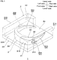
- a wireless power transmission unit 1 (a wireless electric power transmission unit 1) as a first embodiment of a wireless power transmission system of the present invention is described with reference to FIGS. 1 to 2B .
- the wireless power transmission unit 1 includes a power receiving object 3 (an electric power receiving object 3) and a power transmission device 2 (an electric power transmission device 2), and is configured to be capable of wirelessly transmitting an electric power from the power transmission device 2 to the power receiving object 3.
- a wireless power transmission system of the wireless power transmission unit 1 is not particularly limited as long as the electric power can be transmitted by a magnetic field, and any one of an electromagnetic induction-type and a magnetic field resonance-type may be used.
- a predetermined direction perpendicular to the vertical direction is referred to as a front-rear direction (first direction)
- the lower-left side on the plane of the sheet in FIG. 1 is referred to as a front side (one side in the first direction)
- the upper-right side on the plane of the sheet in FIG. 1 is referred to as a rear side (the other side in the first direction).
- the vertical direction is the same direction as a gravity direction (hereinafter, the same).
- the direction perpendicular to both directions of the vertical direction and the front-rear direction is referred to as a right-left direction (second direction)
- the lower-right side on the plane of the sheet in FIG. 1 is referred to as a right side (one side in the second direction)
- the upper-left side on the plane of the sheet in FIG. 1 is referred to as a left side (the other side in the second direction).
- directions are in conformity with direction arrows described in each view.
- the power receiving object 3 is not particularly limited, and examples thereof include wearable device that is capable of being mounted on a human body (for example, head mount display, brain wave sensor, glasses, smart watch, ring, or the like), AV equipment (for example, portable music player, IC recorder, portable DVD player, or the like), medical equipment (for example, measuring apparatus, treatment apparatus, or the like), and voice communication terminal (for example, cellular phone, smart phone, or the like).
- a human body for example, head mount display, brain wave sensor, glasses, smart watch, ring, or the like
- AV equipment for example, portable music player, IC recorder, portable DVD player, or the like
- medical equipment for example, measuring apparatus, treatment apparatus, or the like
- voice communication terminal for example, cellular phone, smart phone, or the like.
- the power receiving object 3 is the wearable device.
- a case where the power receiving object is a head mount display (hereinafter, referred to as a HMD 3) is described; in the third embodiment, a case where the power receiving object is a brain wave sensor 4 is described; and in the fourth embodiment, a case where the power receiving object is a smart glass 5 is described.
- the HMD 3 is a non-transmissive head mount display.
- the HMD 3 is used by being mounted on a head portion of a user, and is configured to display an image in front of the user's eyes who is mounted with it.
- the HMD 3 includes a display portion 33 and a mounting portion 34.
- the display portion 33 In a state where the HMD 3 is mounted on the user, the display portion 33 is positioned in front of the user's eyes and is capable of displaying an image for the user.
- the mounting portion 34 is capable of being mounted along the head portion of the user.
- the mounting portion 34 supports the display portion 33 so that the display portion 33 is positioned in front of the user's eyes in a state of being mounted on the head of the user.
- the mounting portion 34 is continuous to the display portion 33.
- a structure of the mounting portion 34 is not particularly limited, and in the first and the second embodiments, the mounting portion 34 consists of one pair of temple portions 34A that are disposed at spaced intervals to each other in a right-left direction. Each of the one pair of temple portions 34A extends in a front-rear direction continuously from the end portion in the right-left direction of the display portion 33.
- the HMD 3 includes a power receiving unit 30 (an electric power receiving unit 30) and a secondary cell 32 (ref: FIG. 3 ).
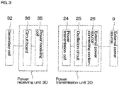
- the power receiving unit 30 is embedded in the side portion of the HMD 3. As shown in FIG. 3 , the power receiving unit 30 includes a power receiving coil 35 (an electric power receiving coil 35) as one example of a power receiving portion, and a circuit board 36.
- a power receiving coil 35 an electric power receiving coil 35
- a circuit board 36 a circuit board 36.
- the power receiving coil 35 is capable of receiving an electric power that is wirelessly transmitted from a power transmission coil 24 (an electric power transmission col 24) (described later). To be specific, the power receiving coil 35 is capable of generating an electric power by a magnetic field generated from the power transmission coil 24 (described later). Although not shown, the power receiving coil 35 is formed from a wire extending in a spiral shape. The wire is, for example, formed from an electrically conductive metal such as copper. In a state where the HMD 3 is horizontally placed, an axis of the power receiving coil 35 crosses the vertical direction (gravity direction), and preferably, is perpendicular to the vertical direction (gravity direction).
- the circuit board 36 is configured to supply an electric current from the power receiving coil 35 to the secondary cell 32 at the time of charging of the secondary cell 32, and is also configured to supply the electric current from the secondary cell 32 to the display portion 33 at the time of discharging of the secondary cell 32.
- the circuit board 36 includes a wire pattern, and a control element.
- the wire pattern is electrically connected to each of the display portion 33, the power receiving coil 35, and the secondary cell 32.
- the control element controls the electric power that flows in the wire pattern.
- the control element includes a rectifier (AC/DC converter), a charging controller, a transformer, or the like.
- the secondary cell 32 is a chargeable and dischargeable cell, and examples thereof include lithium ion secondary cell, nickel-hydrogen secondary cell, and silver-zinc secondary cell.
- the HMD 3 further includes a contact surface 31.
- the contact surface 31 is a portion of the outer-surface of the HMD 3, and to be more specific, is a portion of the peripheral surface of the HMD 3 extending in the vertical direction.
- the contact surface 31 includes a first contact portion 31A and a second contact portion 31B.
- the first contact portion 31A is positioned on the side surface of the HMD 3.
- the first contact portion 31A is disposed so as to be overlapped with the power receiving unit 30 (the power receiving coil 35) when projected in the right-left direction.
- the first contact portion 31A is disposed at the same side as the side at which the power receiving unit 30 is provided in the right-left direction.
- the first contact portion 31A is positioned at spaced intervals to the power receiving unit 30 in the right-left direction.
- the first contact portion 31A extends so as to cross the right-left direction, and preferably, extends along the front-rear direction so as to be perpendicular to the right-left direction.
- the second contact portion 31B is positioned on the front surface of the HMD 3.
- the second contact portion 31B is disposed so as to be overlapped with the power receiving unit 30 (the power receiving coil 35) when projected in the front-rear direction.
- the second contact portion 31B is positioned at spaced intervals to the power receiving unit 30 in the front-rear direction.
- the second contact portion 31B is continuous to the first contact portion 31 A.
- the second contact portion 31B has a generally circular arc shape when viewed from the top.
- the second contact portion 31B is continuous from the front end portion of the first contact portion 31A, and curves inwardly in the right-left direction (center in the right-left direction of the HMD 3) toward the front side.
- the power transmission device 2 enables the placement of the HMD 3, and is capable of transmitting the electric power to the HMD 3 that is placed thereon.
- the power transmission device 2 includes a placement portion 23, a plurality of wall portions 21, and a plurality of power transmission units 20 (electric power transmission units 20).
- the placement portion 23 enables the placement of the HMD 3.
- the placement portion 23 has a rectangular flat plate shape when viewed from the top.
- the placement portion 23 has a predetermined thickness, extends in the front-rear direction and the right-left direction, and has a flat front surface (upper surface) and a flat rear surface (lower surface).
- the upper surface of the placement portion 23 is defined as a placement surface 23A.
- the plurality of wall portions 21 are disposed on the placement surface 23A of the placement portion 23, and are integrally provided with the placement portion 23. Each of the plurality of wall portions 21 extends in the vertical direction (gravity direction).
- the plurality of wall portions 21 are the two wall portions 21, and consist of a first wall portion 21A and a second wall portion 21B.
- the first wall portion 21A and the second wall portion 21B are disposed in both end portions in the right-left direction of the placement surface 23A, and face at spaced intervals to each other in the right-left direction.
- Each of the inner-surfaces in the right-left direction of the first wall portion 21A and the second wall portion 21B extends in the vertical direction.
- the inner-surface in the right-left direction of the first wall portion 21A, the inner-surface in the right-left direction of the second wall portion 21B, and the placement surface 23A define a housing space 2A that is capable of housing the HMD 3.
- the first wall portion 21A and the second wall portion 21B are configured to be point-symmetrical (180° rotationally symmetrical) when viewed from the top. Of the first wall portion 21A and the second wall portion 21B, the first wall portion 21A is described, and the description of the second wall portion 21B is omitted.
- the first wall portion 21A is the wall portion 21 at the right side of the two wall portions 21.
- the inner-surface in the right-left direction of the first wall portion 21A includes a positioning surface 22 as one example of a positioning portion. That is, the wall portion 21 functions as a positioning portion as well.
- the positioning surface 22 positions the HMD 3 that is placed on the power transmission device 2.
- the positioning surface 22 of the first wall portion 21A can position (ref: FIG. 2A ) the HMD 3 in a first position (described later), and the positioning surface 22 of the second wall portion 21B can position (ref: FIG. 2B ) the HMD 3 in a second position (described later). That is, the positioning surface 22 (the positioning surface 22 of the first wall portion 21A or the positioning surface 22 of the second wall portion 21B) can position the HMD 3 in one position.
- the plurality of positioning surfaces 22 can position the HMD in the plurality of positions.
- the positioning surface 22 includes a first positioning portion 22A and a second positioning portion 22B.
- the first positioning portion 22A corresponds to the first contact portion 31A of the contact surface 31, and the first positioning portion 22A has the same shape as that of the first contact portion 31A.
- the first positioning portion 22A extends so as to cross the right-left direction, and preferably, extends along the front-rear direction so as to be perpendicular to the right-left direction.
- the second positioning portion 22B is positioned at the front side with respect to the first positioning portion 22A.
- the second positioning portion 22B corresponds to the second contact portion 31B of the contact surface 31.
- the second positioning portion 22B has the same shape as that of the second contact portion 31B.
- the second positioning portion 22B has a generally circular arc shape when viewed from the top.
- the second positioning portion 22B is continuous to the first positioning portion 22A.
- the second positioning portion 22B is continuous from the front end portion of the first positioning portion 22A, and curves inwardly in the right-left direction (center in the right-left direction of the HMD 3) toward the front side.
- the one power transmission unit 20 is provided in each of the wall portions 21.
- the plurality of power transmission units 20 are the two power transmission units 20, and consist of a first power transmission unit 20A (a first electric power transmission unit 20A) provided in the first wall portion 21A and a second power transmission unit 20B (a second electric power transmission unit 20B) provided in the second wall portion 21B.
- each of the power transmission units 20 includes the power transmission coil 24 as one example of a power transmission portion (an electric power transmission portion), an oscillation circuit 25, and an external power source-connecting portion 26. That is, each of the wall portions 21 is provided with the one power transmission coil 24, and the power transmission device 2 includes the plurality of power transmission coils 24 (the power transmission coil 24 of the first power transmission unit 20A and the power trasmission coil 24 of the second power transmission unit 20B).
- the plurality of power transmission coils 24 are provided corresponding to the plurality of positions of the HMD 3.
- the first power transmission unit 20A and the second power transmission unit 20B have the same structure, and are disposed so as to be point-symmetrical (180° rotationally symmetrical) when viewed from the top. Then, of the first power transmission unit 20A and the second power transmission unit 20B, the first power transmission unit 20A is described, and the description of the second power transmission unit 20B is omitted.
- the first power transmission unit 20A is embedded in the first wall portion 21A.
- the first power transmission unit 20A (the power transmission coil 24) is disposed so as to be overlapped with the front end portion of the first positioning portion 22A of the positioning surface 22 when projected in the right-left direction.
- the first power transmission unit 20A is positioned outwardly in the right-left direction at spaced intervals to the front end portion of the first positioning portion 22A.
- the power transmission coil 24 of the first power transmission unit 20A is provided corresponding to the first position of the HMD 3 (ref: FIG. 2A ).
- the power transmission coil 24 of the second power transmission unit 20B is provided corresponding to the second position of the HMD 3 (ref: FIG. 2B ).
- the power transmission coil 24 is capable of wirelessly transmitting the electric power to the power receiving coil 35.
- the power transmission coil 24 is capable of wirelessly transmitting the electric power in the right-left direction (horizontal direction), and generating the magnetic field.
- the power transmission coil 24 may have the same structure as that of the power receiving coil 35, or may be a spiral coil obtained by winding around a wire material such as copper wire.
- the axis of the power transmission coil 24 extends so as to cross the vertical direction, and preferably extends along the right-left direction so as to be perpendicular to the vertical direction.
- the oscillation circuit 25 is capable of generating an electric power having a frequency of, for example, 1 MHz or more and 10 MHz or less, preferably 1 MHz or more and 5 MHz or less.
- the oscillation circuit 25 is electrically connected to each of the power transmission coil 24 and the external power source-connecting portion 26.
- Examples of the oscillation circuit 25 include LC oscillation circuit, CR oscillation circuit, crystal oscillation circuit, and switching circuit.
- the external power source-connecting portion 26 is capable of being connected to an external power source 9 that is provided at the outside of the wireless power transmission unit 1. Examples of the external power source-connecting portion 26 include AC adapter and USB terminal.
- the external power source-connecting portion 26 is connected to the external power source 9, and all of the plurality of power transmission coils 24 periodically transmit the electric power.
- the electric power transmitted periodically may be the same as or lower than the electric power transmitted continuously to be described later.
- the plurality of wall portions 21 allow the insertion of the HMD 3 when the HMD 3 is inserted into the housing space 2A so as to be positioned in the first position (ref: FIG. 2A ) where the display portion 33 is at the front side or in the second position (ref: FIG. 2B ) where the display portion 33 is at the rear side. Meanwhile, the plurality of wall portions 21 are brought into contact with the HMD 3 and prohibit the insertion of the HMD 3 with respect to the housing space 2A when the HMD 3 is inserted into the housing space 2A so as to be positioned in another position excluding the first position and the second position.
- the HMD 3 when the HMD 3 is housed in the housing space 2A so as to be positioned in the first position, the HMD 3 is placed horizontally on the placement surface 23A of the placement portion 23.
- the contact surface 31 is brought into contact with the positioning surface 22 included in the first wall portion 21A.
- the first contact portion 31A of the contact surface 31 is brought into contact with the first positioning portion 22A of the positioning surface 22 in the right-left direction
- the second contact portion 31B of the contact surface 31 is brought into contact with the second positioning portion 22B of the positioning surface 22 in the front-rear direction.
- the positioning surface 22 of the second wall portion 21B may be in contact with the HMD 3 in the right-left direction or may be positioned at minute spaced intervals thereto in the right-left direction.
- the positioning surface 22 of the first wall portion 21A positions the HMD 3 in the horizontal direction (front-rear direction and right-left direction), and positions the HMD 3 in the first position.
- the power receiving unit 30 faces the first power transmission unit 20A at spaced intervals thereto in the right-left direction.
- the power receiving coil 35 faces the power transmission coil 24 of the first power transmission unit 20A in the right-left direction.
- the power receiving coil 35 receives the electric power that is periodically transmitted from the power transmission coil 24 of the first power transmission unit 20A.
- the power receiving coil 35 receives the electric power from the power transmission coil 24 of the first power transmission unit 20A, so that a voltage, a standing wave ratio, impedance, or the like fluctuate in the power transmission coil 24 of the first power transmission unit 20A. Meanwhile, the electric power from the power transmission coil 24 of the second power transmission unit 20B is not received by the power receiving coil 35, so that in the power transmission coil 24 of the second power transmission unit 20B, the voltage, the standing wave ratio, the impedance, or the like do not fluctuate. When the power receiving coil 35 receives the electric power, load resistance of the circuit board 36 may fluctuate. In this manner, in the power transmission coil 24 that transmits the electric power to the power receiving coil 35, the voltage, the standing wave ratio, the impedance, or the like fluctuate.
- the power transmission device 2 detects the power transmission coil 24 (the power transmission coil 24 of the first power transmission unit 20A) having a relatively large fluctuation amount of the voltage, the standing wave ratio, the impedance, or the like.
- the power transmission device 2 detects that the HMD 3 is placed in the first position, and specifies the power transmission coil 24 (the power transmission coil 24 of the first power transmission unit 20A) having the best transmission efficiency with respect to the power receiving coil 35.
- the circuit board 36 may transmit the situation of the secondary cell 32 (for example, remaining battery capacity or the like) to the power transmission device 2 as a digital signal by discrete fluctuation of the load resistance. In this manner, the power transmission device 2 can receive the situation of the secondary cell 32.
- the situation of the secondary cell 32 for example, remaining battery capacity or the like
- the power transmission device 2 stops the periodical power transmission from the power transmission coil 24 of the second power transmission unit 20B.
- the power transmission device 2 continuously transmits the electric power from the power transmission coil 24 of the first power transmission unit 20A.
- the specific power transmission coil 24 (the power transmission coil 24 of the first power transmission unit 20A) transmits the electric power to the power receiving coil 35, and of the plurality of power transmission coils 24, another power transmission coil 24 excluding the specific power transmission coil 24 (the power transmission coil 24 of the second power transmission unit 20B) stops the power transmission.
- the power receiving coil 35 receives the electric power that is transmitted from the specific power transmission coil 24.
- the contact surface 31 is brought into contact with the positioning surface 22 included in the second wall portion 21B.
- the first contact portion 31A is in contact with the first positioning portion 22A in the right-left direction
- the second contact portion 3 1B is in contact with the second positioning portion 22B in the front-rear direction.
- the positioning surface 22 of the second wall portion 21B positions the HMD 3 in the horizontal direction (front-rear direction and right-left direction), and positions the HMD 3 in the second position.
- the power receiving unit 30 faces the second power transmission unit 20B at spaced intervals thereto in the right-left direction.
- the power receiving coil 35 faces the power transmission coil 24 of the second power transmission unit 20B in the right-left direction.
- the power transmission device 2 detects the placement of the HMD 3 in the second position in the same manner as the description above, and specifies the power transmission coil 24 (the power transmission coil 24 of the second power transmission unit 20B) having the best transmission efficiency with respect to the power receiving coil 35. Thereafter, the power transmission device 2 stops the periodical power transmission from the power transmission coil 24 of the first power transmission unit 20A.
- the power transmission device 2 continuously transmits the electric power from the power transmission coil 24 of the second power transmission unit 20B. Then, the power receiving coil 35 receives the electric power transmitted from the power transmission coil 24 of the second power transmission unit 20B.
- the HMD 3 receives the electric power by the positioning surface 22 in a state of being positioned in the first position or the second position.
- the electric power is supplied from the power receiving coil 35 to the secondary cell 32 via the circuit board 36.
- the secondary cell 32 is charged.
- the circuit board 36 transmits a communication signal (digital signal) to the power transmission device 2 in the same manner as the description above, and the power transmission device 2 stops the power transmission by the communication signal from the circuit board 36.
- the electric power charged in the secondary cell 32 is appropriately supplied from the secondary cell 32 to the display portion 33 via the circuit board 36 to operate the display portion 33.
- the electric power received by the power receiving coil 35 can be directly supplied to the display portion 33 via the circuit board 36 without being supplied to the secondary cell 32 via the circuit board 36.
- the specific power transmission coil 24 transmits the electric power to the power receiving coil 35.
- a reduction in electric power consumption can be achieved.
- the HMD 3 is positioned by the positioning surface 22.
- the power receiving coil 35 that is positioned can efficiently receive the electric power from the specific power transmission coil 24, and improvement of the transmission efficiency of the electric power can be achieved.
- the power transmission coil 24 of the first power transmission unit 20A is provided in the first wall portion 21A
- the power transmission coil 24 of the second power transmission unit 20B is provided in the second wall portion 21B.
- Each of the first wall portion 21A and the second wall portion 21B includes the positioning surface 22.
- the power receiving coil 35 In the HMD 3, there is a limit in space where the power receiving coil 35 can be disposed. Thus, when the power transmission coil 24 is provided in the placement portion 23, the power receiving coil 35 cannot be disposed in a preferable position with respect to the power transmission coil 24 at the time of the placement of the HMD 3, so that the transmission efficiency of the electric power is reduced. Meanwhile, in the power transmission device 2, the power transmission coil 24 is provided in the wall portion 21, so that the power receiving coil 35 can be disposed in a preferable position with respect to the power transmission coil 24 at the time of the placement of the HMD 3.
- the wall portion 21 is integrally provided with the placement portion 23.
- a placement posture of the HMD 3 can be set.
- the power transmission coil 24 can further more surely transmit the electric power to the power receiving coil 35 in a state where the HMD 3 is positioned by the wall portion 21, and the improvement of the transmission efficiency of the electric power can be further more surely achieved.
- the large number of (for example, three or more) power transmission coils 24 are required to configure the power transmission device 2 so as to be capable of transmitting the electric power with respect to the entire housing space 2A that houses the HMD 3.
- the positioning surface 22 (the positioning surface 22 of the first wall portion 21A and the positioning surface 22 of the second wall portion 21B) can position the HMD 3 in the plurality of positions, and the plurality of power transmission coils 24 are provided corresponding to the plurality of positions of the HMD 3.
- the electric power can be efficiently wirelessly transmitted from the corresponding power transmission coil 24 to the power receiving coil 35 in a state where the HMD 3 is positioned in each of the positions, while a reduction in number of the power transmission coil 24 can be achieved.
- the power transmission device 2 detects the position of the HMD 3 by the transmission of the electric power between the power transmission coil 24 and the power receiving coil 35, and specifies the power transmission coil 24 having the best transmission efficiency with respect to the power receiving coil 35.
- a specifying method of the power transmission coil 24 is not particularly limited.
- the power transmission device 2 mechanically or optically detects the position of the HMD 3, and may specify the power transmission coil 24 having the best transmission efficiency with respect to the power receiving coil 35.
- An example of a mechanical detecting method includes a method in which a mechanical switch corresponding to each of the power transmission units 20 is provided so as to be contactable with the contact surface 31.
- An example of an optical detecting method includes a method in which a reflection-type optical sensor corresponding to each of the power transmission units 20 is provided so as to be reflectable on the contact surface 31.
- the second embodiment of the present invention is described with reference to FIG. 4 .
- the same reference numerals are provided for members corresponding to each of those in the above-described first embodiment, and their detailed description is omitted.
- the power transmission device 2 is capable of housing the HMD 3.
- the present invention is not limited to this.
- the power transmission device 2 when the HMD 3 is disposed in any one of the four positions, the power transmission device 2 is capable of housing the HMD 3.
- the power transmission device 2 includes the four power transmission units 20 including the power transmission coils 24 corresponding to the four positions of the HMD 3.
- the power transmission device 2 includes the four wall portions 21, each of which is provided with the power transmission unit 20.
- the four wall portions 21 are disposed at spaced intervals to each other in a peripheral direction of a symmetric axis so as to be 90° rotationally symmetrical with the predetermined symmetric axis as the center.
- Each of the four wall portions 21 has the positioning surface 22.
- the positioning surfaces 22 of the four wall portions 21, and the placement surface 23A define the housing space 2A that is capable of housing the HMD 3.
- the four wall portions 21 allow the insertion of the HMD 3 when the HMD 3 is inserted into the housing space 2A so as to be positioned in any one of the first position (not shown) where the display portion 33 is at the front side, the second position (not shown) where the display portion 33 is at the rear side, the third position (not shown) where the display portion 33 is at the right side, and the fourth position where the display portion 33 is at the left side.
- the four wall portions 21 are brought into contact with the HMD 3 and prohibit the insertion of the HMD 3 with respect to the housing space 2A when the HMD 3 is inserted into the housing space 2A so as to be positioned in another position excluding the four positions.
- the contact surface 31 is brought into contact with the positioning surface 22 included in the corresponding wall portion 21. In this manner, the HMD 3 is positioned in any one of the four positions.
- the power transmission device 2 detects the placement of the HMD 3 in any one of the above-described four positions in the same manner as the description above, specifies the power transmission coil 24 having the best transmission efficiency with respect to the power receiving coil 35, and stops the power transmission from another power transmission coil 24.
- the power transmission device 2 continuously transmits the electric power from the specific power transmission coil 24, and the power receiving coil 35 receives the electric power transmitted from the specific power transmission coil 24.
- the HMD 3 receives the electric power by the positioning surface 22 in a state of being positioned in any one of the above-described four positions.
- the same function and effect as that of the first embodiment can be achieved.
- the first embodiment is preferable.
- FIGS. 5A and 5B the same reference numerals are provided for members corresponding to each of those in the above-described first and second embodiments, and their detailed description is omitted.
- the power receiving object is the HMD 3.
- the power receiving object is not particularly limited.
- the power receiving object is a brain wave sensor 4.
- the brain wave sensor 4 is used by being mounted on the head portion of the user, and is configured to measure a brain wave of the user who is mounted with it.
- the brain wave sensor 4 includes a sensor portion 43 and a mounting portion 44.
- the sensor portion 43 is capable of measuring the brain wave of the user.
- the sensor portion 43 has a semi-circular arc shape when viewed from the top having an opening rearwardly.
- the sensor portion 43 has a first surface 45, a second surface 46, a third surface 47, a fourth surface 48, and a plurality of (two) contact surfaces 49.
- the first surface 45 is a surface that is positioned at the upper side in a state where the brain wave sensor 4 is mounted on the user.
- the second surface 46 is a surface that is positioned at the lower side in a state where the brain wave sensor 4 is mounted on the user.
- the first surface 45 and the second surface 46 are positioned at spaced intervals to each other in the vertical direction.
- the third surface 47 is the outer-peripheral surface (front-side peripheral surface) of the sensor portion 43, and has a semi-circular arc shape when viewed from the top.
- the third surface 47 connects the front end edge of the first surface 45 to that of the second surface 46 in the vertical direction.
- the fourth surface 48 is the inner-peripheral surface (rear-side peripheral surface) of the sensor portion 43, and has a semi-circular arc shape when viewed from the top.
- the fourth surface 48 is positioned at the rear side of the third surface 47 at spaced intervals thereto in a radial direction of the sensor portion 43.
- the plurality of (two) contact surfaces 49 are provided corresponding to a plurality of positioning portions 29 to be described later.
- the plurality of (two) contact surfaces 49 are the two contact surfaces 49.
- Each of the two contact surfaces 49 connects the end portion in the right-left direction of the third surface 47 to that in the right-left direction of the fourth surface 48 in the right-left direction, and connects the first surface 45 to the second surface 46 in the vertical direction.
- Each of the two contact surfaces 49 extends in the vertical direction.
- the two contact surfaces 49 are positioned at spaced intervals to each other in the right-left direction.
- the mounting portion 44 is capable of being mounted along the head portion of the user.
- the mounting portion 44 supports the sensor portion 43 so that the sensor portion 43 is positioned in the front head portion of the user in a state of being mounted on the head portion of the user.
- the mounting portion 44 has a semi-circular arc shape when viewed from the top having an opening forwardly.
- One end portion (right end portion) of the mounting portion 44 is connected to the contact surface 49 at the right side of the sensor portion 43, and the other end portion (left end portion) of the mounting portion 44 is connected to the contact surface 49 at the left side of the sensor portion 43.
- the brain wave sensor 4 includes the power receiving unit 30 and the secondary cell 32 (ref: FIG. 3 ) in the same manner as that in the HMD 3.
- the power receiving unit 30 is embedded in the side portion of the brain wave sensor 4. To be more specific, of the two contact surfaces 49, the power receiving unit 30 is disposed at the front side of the contact surface 49 at the right side at spaced intervals thereto.
- the structure of the secondary cell 32 is the same as the description above.
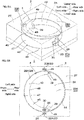
- the power transmission device 2 includes the placement portion 23, a wall portion 27, the plurality of power transmission units 20, and the plurality of (two) positioning portions 29.
- the structure of the placement portion 23 is the same as the description above.
- the wall portion 27 is integrally provided with the placement portion 23.
- the wall portion 27 extends from the entire placement surface 23A of the placement portion 23 in the vertical direction.
- the wall portion 27 has an opening portion 28.
- the opening portion 28 has a circular shape when viewed from the top, and passes through the wall portion 27 in the vertical direction. In this manner, the central portion of the placement surface 23A of the placement portion 23 is exposed from the upper side via the opening portion 28.
- An inner-peripheral surface 28A of the opening portion 28 and the placement surface 23A exposed from the wall portion 27 define the housing space 2A that is capable of housing the brain wave sensor 4.
- a radius of the inner-peripheral surface 28A of the opening portion 28 is generally the same as a radius of curvature of the third surface 47 of the sensor portion 43.
- the plurality of power transmission units 20 are provided in the wall portion 27.
- the plurality of power transmission units 20 are the two power transmission units 20, and consist of the first power transmission unit 20A that is embedded in the right end portion of the wall portion 27, and the second power transmission unit 20B that is embedded in the left end portion of the wall portion 27.
- the first power transmission unit 20A is positioned at the right side of the opening portion 28 at spaced intervals thereto.
- the power transmission coil 24 of the first power transmission unit 20A is provided corresponding to the first position (described later) of the brain wave sensor 4.
- the second power transmission unit 20B is positioned at the left side of the opening portion 28 at spaced intervals thereto.
- the power transmission coil 24 of the second power transmission unit 20B is provided corresponding to the second position (described later) of the brain wave sensor 4.
- the plurality of positioning portion 29 position the brain wave sensor 4 that is placed on the power transmission device 2.
- the plurality of positioning portions 29 are provided so as to be in contact with the corresponding contact surface 49 in the front-rear direction when the brain wave sensor 4 is housed in the housing space 2A.
- the plurality of positioning portions 29 are disposed at the inside of the housing space 2A and is integrally provided with the placement portion 23.
- the plurality of positioning portions 29 are the two positioning portions 29.
- the two positioning portions 29 are disposed at spaced intervals to each other in the right-left direction.
- the positioning portion 29 at the right side is positioned at the rear-left side of the first power transmission unit 20A at spaced intervals thereto, and the positioning portion 29 at the left side is positioned at the rear-right side of the second power transmission unit 20B at spaced intervals thereto.
- Each of the two positioning portions 29 protrudes upwardly from the placement surface 23A.
- the plurality of positioning portions 29 allow the insertion of the brain wave sensor 4 when the brain wave sensor 4 is inserted into the housing space 2A so as to be positioned in the first position or the second position (not shown).
- the sensor portion 43 In the first position of the brain wave senor 4, the sensor portion 43 is positioned at the front side, the first surface 45 is positioned at the upper side, and the second surface 46 is positioned at the lower side.
- the second position of the brain wave sensor 4 is a position that is reversed from the first position in an up-down direction.
- the sensor portion 43 is positioned at the front side, the first surface 45 is positioned at the lower side, and the second surface 46 is positioned at the upper side.
- the plurality of positioning portions 29 are brought into contact with the brain wave sensor 4 and prohibit the insertion of the brain wave sensor 4 with respect to the housing space 2A when the brain wave sensor 4 is inserted into the housing space 2A so as to be positioned in another position excluding the first position and the second position.
- the brain wave sensor 4 When the brain wave sensor 4 is housed in the housing space 2A so as to be positioned in the first position or the second position, the brain wave sensor 4 is placed horizontally on the placement surface 23A of the placement portion 23.
- the contact surface 49 is positioned at the front side with respect to the corresponding positioning portion 29 and is brought into contact with the corresponding positioning portion 29 in the front-rear direction.
- the third surface 47 of the sensor portion 43 faces the inner-peripheral surface 28A of the opening portion 28.
- the third surface 47 may be in contact with the inner-peripheral surface 28A or may be positioned at minute spaced intervals thereto.
- the positioning portion 29 positions the brain wave sensor 4 in the horizontal direction (front-rear direction), and positions the brain wave sensor 4 in the first position or the second position.
- the power transmission device 2 detects that the brain wave sensor 4 is placed in the first position or the second position in the same manner as the description above, specifies the power transmission coil 24 having the best transmission efficiency with respect to the power receiving coil 35, and stops the power transmission of another power transmission coil 24.
- the power transmission device 2 continuously transmits the electric power from the specific power transmission coil 24.
- the power receiving coil 35 receives the electric power that is transmitted from the specific power transmission coil 24.
- the brain wave sensor 4 receives the electric power by the positioning portion 29 in a state of being positioned in the first position or the second position.
- FIGS. 6A and 6B the fourth embodiment of the present invention is described with reference to FIGS. 6A and 6B .
- the same reference numerals are provided for members corresponding to each of those in the above-described first to third embodiments, and their detailed description is omitted.
- the power receiving object is the smart glass 5.
- the smart glass 5 is an eyeglass-type, and is a transmissive head mount device.
- the smart glass 5 includes a glass portion 53 and a mounting portion 54.
- the glass portion 53 includes two lenses 55 and a frame body 56.
- the two lenses 55 are positioned in front of the user's eyes in a state where the smart glass 5 is mounted on the user.
- the lenses 55 are optically transmissive, and is capable of displaying an image for the user.
- the frame body 56 supports the two lenses 55.
- the frame body 56 includes a first end portion 57 that is positioned at the upper end, and a second end portion 58 that is positioned at the lower end in a state where the smart glass 5 is mounted on the user.
- the first end portion 57 and the second end portion 58 are positioned at spaced intervals to each other in the vertical direction.
- the mounting portion 54 supports the glass portion 53 so that the glass portion 53 is positioned in front of the user's eyes in a state of being mounted on the head portion of the user.
- the mounting portion 54 consists of one pair of temple portions 54A that are disposed at spaced intervals to each other in the right-left direction.
- Each of the one pair of temple portions 54A is pivotably fixed to the end portion in the right-left direction of the frame body 56 with a rotational axis extending in the vertical direction as a supporting point. In this manner, each of the one pair of temple portions 54A is pivotable in a developing position that extends in the front-rear direction, and in a folding position that is folded with respect to the frame body 56 and extends in the right-left direction.
- the smart glass 5 includes the power receiving unit 30 and the secondary cell 32 (ref: FIG. 3 ) in the same manner as that of the HMD 3.
- the power receiving unit 30 is embedded in the side portion of the smart glass 5.
- the power receiving unit 30 is embedded in the right end portion of the frame body 56.
- the structure of the secondary cell 32 is the same as the description above.
- the power transmission device 2 includes the placement portion 23, the wall portion 27, and the plurality of power transmission units 20.
- the structure of the placement portion 23 is the same as the description above.
- the wall portion 27 has the opening portion 28.
- the opening portion 28 has a generally elliptical shape when viewed from the top, and passes through the wall portion 27 in the vertical direction. In this manner, the central portion of the placement surface 23A of the placement portion 23 is exposed from the upper side via the opening portion 28.
- An inner-peripheral surface 28B of the opening portion 28 and the placement surface 23A exposed from the wall portion 27 define the housing space 2A that is capable of housing the smart glass 5.
- the inner-peripheral surface 28B of the opening portion 28 includes a first inner-peripheral portion 28C as one example of a positioning portion and a second inner-peripheral portion 28D.
- the first inner-peripheral portion 28C is a front-side portion of the inner-peripheral surface 28B.
- the first inner-peripheral portion 28C has a shape along the frame body 56 of the smart glass 5, and has a U-shape having an opening rearwardly when viewed from the top.
- the second inner-peripheral portion 28D is a rear-side portion of the inner-peripheral surface 28B.
- the second inner-peripheral portion 28D is continuous to the first inner-peripheral portion 28C.
- the second inner-peripheral portion 28D has a U-shape having an opening forwardly when viewed from the top.
- the second inner-peripheral portion 28D does not have a shape along the frame body 56 of the smart glass 5, and has a smaller size (dent) in the front-rear direction compared to the first inner-peripheral portion 28C.
- the plurality of power transmission units 20 are provided in the wall portion 27, and to be specific, consist of the first power transmission unit 20A and the second power transmission unit 20B.
- the power transmission coil 24 of the first power transmission unit 20A is provided corresponding to the first position (described later) of the smart glass 5.
- the power transmission coil 24 of the second power transmission unit 20B is provided corresponding to the second position (described later) of the smart glass 5.
- the wall portion 27 allows the insertion of the smart glass 5 when the one pair of temple portions 54A are positioned in the folding position, and the smart glass 5 is inserted into the housing space 2A so as to be positioned in the first position or the second position (not shown).
- the glass portion 53 In the first position of the smart glass 5, the glass portion 53 is positioned at the front side, the first end portion 57 of the frame body 56 is positioned at the upper side, and the second end portion 58 of the frame body 56 is positioned at the lower side.
- the second position of the smart glass 5 is a position that is reversed from the first position in the up-down direction.
- the glass portion 53 is positioned at the front side, the first end portion 57 of the frame body 56 is positioned at the lower side, and the second end portion 58 of the frame body 56 is positioned at the upper side.
- the wall portion 27 is brought into contact with the smart glass 5, and prohibits the entry of the smart glass 5 with respect to the housing space 2A.
- the smart glass 5 When the smart glass 5 is housed in the housing space 2A so as to be positioned in the first position or the second position in a state where the one pair of temple portions 54A are positioned in the folding position, the smart glass 5 is placed horizontally on the placement surface 23A of the placement portion 23.
- the frame body 56 is positioned at the rear side with respect to the first inner-peripheral portion 28C of the opening portion 28 and is brought into contact with the first inner-peripheral portion 28C in the front-rear direction.
- the one pair of temple portions 54A in the folding position are positioned at the front side of the second inner-peripheral portion 28D of the opening portion 28 at spaced intervals thereto.
- the first inner-peripheral portion 28C of the opening portion 28 positions the smart glass 5 in the horizontal direction (front-rear direction and right-left direction), and positions the smart glass 5 in the first position or the second position.
- the power transmission device 2 detects that the smart glass 5 is placed in the first position or the second position in the same manner as the description above, specifies the power transmission coil 24 having the best transmission efficiency with respect to the power receiving coil 35, and stops the power transmission of another power transmission coil 24.
- the power transmission device 2 continuously transmits the electric power from the specific power transmission coil 24.
- the power receiving coil 35 receives the electric power that is transmitted from the specific power transmission coil 24.
- the smart glass 5 receives the electric power by the first inner-peripheral portion 28C of the wall portion 27 in a state of being positioned in the first position or the second position.
- the wireless power transmission system of the present invention can be applied for various industrial products, and among all, can be preferably used for wearable devices, AV equipment, medical equipment, voice communication terminals, or the like.
Landscapes
- Engineering & Computer Science (AREA)
- Power Engineering (AREA)
- Computer Networks & Wireless Communication (AREA)
- Charge And Discharge Circuits For Batteries Or The Like (AREA)
Abstract
Description
- The present invention relates to a wireless power transmission system.
- Conventionally, a wireless power transmission system has been known in which an electric power is wirelessly transmitted from a power transmission device to a power receiving object by using wireless power transmission such as electromagnetic induction-type and magnetic field resonance-type. The power transmission device includes a power transmission coil that generates the magnetic field, and the power receiving object includes a power receiving coil that receives the electric power by the magnetic field generated by the power transmission coil.
- The wireless power transmission system is used for various industrial products, and for example, a power receiving and supplying system in which the power receiving object is a hearing aid, and the power transmission device is a battery charger has been proposed (ref: for example, Patent Document 1).
- In the power receiving and supplying system, the battery charger includes a housing cup having a housing space that is capable of housing the hearing aid, and a plurality of power transmission coils disposed so as to generate a magnetic field in the entire housing space.
- In the power receiving and supplying system, the electric power is transmitted from the power transmission coil to the power receiving coil in a state where the hearing aid is housed in the housing space of the housing cup regardless of the direction and the position of the hearing aid.
- Patent Document 1: Japanese Unexamined Patent Publication No.
2017-135831 - In the power receiving and supplying system described in
Patent Document 1, all of the power transmission coils are operated in order to generate the magnetic field in the entire housing space at the time of transmission of the electric power, and thus, there is a limit in achieving a reduction in electric power consumption. - The present invention provides a wireless power transmission system that is capable of achieving a reduction in electric power consumption.
- The present invention [1] includes a wireless power transmission system including a power transmission device including a plurality of power transmission portions, and a power receiving object including a power receiving portion capable of receiving an electric power wirelessly transmitted from the power transmission portion, wherein of the plurality of power transmission portions, a specific power transmission portion transmits the electric power to the power receiving portion.
- According to the structure, of the plurality of power transmission portions, the specific power transmission portion transmits the electric power to the power receiving portion, so that a reduction in electric power consumption can be achieved compared to a case where all of the power transmission portions are operated at the time of transmission of the electric power.
- The present invention [2] includes the wireless power transmission system described in the above-described [1] further including a positioning portion positioning the placed power receiving object, wherein the power receiving object is capable of receiving an electric power in a state of being positioned by the positioning portion.
- According to the structure, the power receiving object is positioned by the positioning portion, so that the power receiving portion that is positioned can efficiently receive the electric power from the specific power transmission portion, so that improvement of transmission efficiency of the electric power can be achieved.
- The present invention [3] includes the wireless power transmission system described in the above-described [2], wherein the power transmission device further includes a wall portion extending in a vertical direction and provided with at least one of the plurality of power transmission portions, and the wall portion also functions as the positioning portion.
- According to the structure, at least one of the plurality of power transmission portions is provided in the wall portion, and the wall portion functions as the positioning portion, so that the power transmission portion can surely transmit the electric power to the power receiving portion in a state where the power receiving object is positioned by the wall portion. Thus, the improvement of the transmission efficiency of the electric power can be surely achieved.
- In various power receiving objects, there is a limit in space where the power receiving portion can be disposed. Thus, when the power transmission portion is provided on the surface on which the power receiving object is placed, there may be a case where the power receiving portion cannot be disposed in a preferable position with respect to the power transmission portion at the time of placement of the power receiving object, so that the transmission efficiency of the electric power is reduced.
- Meanwhile, according to the above-described structure, the power transmission portion is provided in the wall portion, so that even in the above-described case, there may be a case where the power receiving portion can be disposed in a preferable position with respect to the power transmission portion at the time of the placement of the power receiving object.
- The present invention [4] includes the wireless power transmission system described in the above-described [3], wherein the power transmission device further includes a placement portion enabling placement of the power receiving object, and the wall portion is integrally provided with the placement portion.
- According to the structure, the wall portion is integrally provided with the placement portion enabling the placement of the power receiving object, so that a placement posture of the power receiving object can be set. Thus, the power transmission portion can further more surely transmit the electric power to the power receiving portion in a state where the power receiving object is positioned by the wall portion, and the improvement of the transmission efficiency of the electric power can be further more surely achieved.
- The present invention [5] includes the wireless power transmission system described in any one of the above-described [2] to [4], wherein the positioning portion can position the power receiving object in a plurality of positions, and the plurality of power transmission portions are provided corresponding to the plurality of positions of the power receiving object.
- When the power receiving object is a large-sized product compared to a small-sized product such as hearing aid, a large number of (for example, three or more) power transmission portions are required to configure the wireless power transmission system so as to be capable of transmitting the electric power with respect to the entire region enabling the placement of the power receiving object.
- Meanwhile, according to the above-described structure, the positioning portion can position the power receiving object in the plurality of positions, and the plurality of power transmission portions are provided corresponding to the plurality of positions of the power receiving object, so that compared to a case where the electric power is capable of being transmitted with respect to the entire region enabling the placement of the power receiving object, the electric power can be efficiently wirelessly transmitted from the corresponding power transmission portion to the power receiving portion in a state where the power receiving object is positioned in each of the positions, while a reduction in number of the power transmission portion can be achieved.
- As a result, wireless transmission of the electric power is possible in each of the positions of the power receiving object, while a reduction in production cost of the wireless power transmission system can be achieved, so that the improvement of workability of the wireless transmission of the electric power with respect to the power receiving object can be achieved.
- According to the wireless power transmission system of the present invention, a reduction in electric power consumption can be achieved.
-
-
FIG. 1 shows a perspective view of a wireless power transmission unit as a first embodiment of a wireless power transmission system of the present invention. -
FIG. 2A shows a plan view of the wireless power transmission unit shown inFIG. 1 , and shows a state in which a HMD is positioned in a first position. -
FIG. 2B shows a plan view of the wireless power transmission unit shown inFIG. 1 , and shows a state in which a HMD is positioned in a second position. -
FIG. 3 shows a block view of a power transmission unit and a power receiving unit shown inFIG. 1 . -
FIG. 4 shows a plan view of a wireless power transmission unit as a second embodiment of a wireless power transmission system of the present invention. -
FIG. 5A shows a perspective view of a wireless power transmission unit as a third embodiment of a wireless power transmission system of the present invention. -
FIG. 5B shows a plan view of the wireless power transmission unit shown inFIG. 5A . -
FIG. 6A shows a perspective view of a wireless power transmission unit as a fourth embodiment of a wireless power transmission system of the present invention. -
FIG. 6B shows a plan view of the wireless power transmission unit shown inFIG. 6A . - A wireless power transmission unit 1 (a wireless electric power transmission unit 1) as a first embodiment of a wireless power transmission system of the present invention is described with reference to
FIGS. 1 to 2B . - As shown in
FIG. 1 , the wirelesspower transmission unit 1 includes a power receiving object 3 (an electric power receiving object 3) and a power transmission device 2 (an electric power transmission device 2), and is configured to be capable of wirelessly transmitting an electric power from thepower transmission device 2 to thepower receiving object 3. A wireless power transmission system of the wirelesspower transmission unit 1 is not particularly limited as long as the electric power can be transmitted by a magnetic field, and any one of an electromagnetic induction-type and a magnetic field resonance-type may be used. - In the following description, when referring to the direction of the wireless
power transmission unit 1, with a state where the wirelesspower transmission unit 1 is placed on a horizontal surface (flat surface perpendicular to a vertical direction) as a reference, a predetermined direction perpendicular to the vertical direction is referred to as a front-rear direction (first direction), the lower-left side on the plane of the sheet inFIG. 1 is referred to as a front side (one side in the first direction), and the upper-right side on the plane of the sheet inFIG. 1 is referred to as a rear side (the other side in the first direction). The vertical direction is the same direction as a gravity direction (hereinafter, the same). - Also, with a view when the wireless
power transmission unit 1 is viewed from the front side as a reference of the right and the left, the direction perpendicular to both directions of the vertical direction and the front-rear direction is referred to as a right-left direction (second direction), the lower-right side on the plane of the sheet inFIG. 1 is referred to as a right side (one side in the second direction), and the upper-left side on the plane of the sheet inFIG. 1 is referred to as a left side (the other side in the second direction). To be specific, directions are in conformity with direction arrows described in each view. - The power receiving
object 3 is not particularly limited, and examples thereof include wearable device that is capable of being mounted on a human body (for example, head mount display, brain wave sensor, glasses, smart watch, ring, or the like), AV equipment (for example, portable music player, IC recorder, portable DVD player, or the like), medical equipment (for example, measuring apparatus, treatment apparatus, or the like), and voice communication terminal (for example, cellular phone, smart phone, or the like). - In the first to the fourth embodiments, of the above-described power receiving objects, a case where the
power receiving object 3 is the wearable device is described. To be more specific, in the first and the second embodiments, a case where the power receiving object is a head mount display (hereinafter, referred to as a HMD 3) is described; in the third embodiment, a case where the power receiving object is abrain wave sensor 4 is described; and in the fourth embodiment, a case where the power receiving object is asmart glass 5 is described. - The
HMD 3 is a non-transmissive head mount display. TheHMD 3 is used by being mounted on a head portion of a user, and is configured to display an image in front of the user's eyes who is mounted with it. TheHMD 3 includes adisplay portion 33 and a mountingportion 34. - In a state where the
HMD 3 is mounted on the user, thedisplay portion 33 is positioned in front of the user's eyes and is capable of displaying an image for the user. The mountingportion 34 is capable of being mounted along the head portion of the user. The mountingportion 34 supports thedisplay portion 33 so that thedisplay portion 33 is positioned in front of the user's eyes in a state of being mounted on the head of the user. The mountingportion 34 is continuous to thedisplay portion 33. A structure of the mountingportion 34 is not particularly limited, and in the first and the second embodiments, the mountingportion 34 consists of one pair oftemple portions 34A that are disposed at spaced intervals to each other in a right-left direction. Each of the one pair oftemple portions 34A extends in a front-rear direction continuously from the end portion in the right-left direction of thedisplay portion 33. - The
HMD 3 includes a power receiving unit 30 (an electric power receiving unit 30) and a secondary cell 32 (ref:FIG. 3 ). - The
power receiving unit 30 is embedded in the side portion of theHMD 3. As shown inFIG. 3 , thepower receiving unit 30 includes a power receiving coil 35 (an electric power receiving coil 35) as one example of a power receiving portion, and acircuit board 36. - The
power receiving coil 35 is capable of receiving an electric power that is wirelessly transmitted from a power transmission coil 24 (an electric power transmission col 24) (described later). To be specific, thepower receiving coil 35 is capable of generating an electric power by a magnetic field generated from the power transmission coil 24 (described later). Although not shown, thepower receiving coil 35 is formed from a wire extending in a spiral shape. The wire is, for example, formed from an electrically conductive metal such as copper. In a state where theHMD 3 is horizontally placed, an axis of thepower receiving coil 35 crosses the vertical direction (gravity direction), and preferably, is perpendicular to the vertical direction (gravity direction). - The
circuit board 36 is configured to supply an electric current from thepower receiving coil 35 to thesecondary cell 32 at the time of charging of thesecondary cell 32, and is also configured to supply the electric current from thesecondary cell 32 to thedisplay portion 33 at the time of discharging of thesecondary cell 32. Although not shown, thecircuit board 36 includes a wire pattern, and a control element. The wire pattern is electrically connected to each of thedisplay portion 33, thepower receiving coil 35, and thesecondary cell 32. The control element controls the electric power that flows in the wire pattern. The control element includes a rectifier (AC/DC converter), a charging controller, a transformer, or the like. - The
secondary cell 32 is a chargeable and dischargeable cell, and examples thereof include lithium ion secondary cell, nickel-hydrogen secondary cell, and silver-zinc secondary cell. - As shown in
FIG. 1 , theHMD 3 further includes acontact surface 31. Thecontact surface 31 is a portion of the outer-surface of theHMD 3, and to be more specific, is a portion of the peripheral surface of theHMD 3 extending in the vertical direction. Thecontact surface 31 includes afirst contact portion 31A and asecond contact portion 31B. - As shown in
FIG. 2A , thefirst contact portion 31A is positioned on the side surface of theHMD 3. Thefirst contact portion 31A is disposed so as to be overlapped with the power receiving unit 30 (the power receiving coil 35) when projected in the right-left direction. Thefirst contact portion 31A is disposed at the same side as the side at which thepower receiving unit 30 is provided in the right-left direction. Thefirst contact portion 31A is positioned at spaced intervals to thepower receiving unit 30 in the right-left direction. Thefirst contact portion 31A extends so as to cross the right-left direction, and preferably, extends along the front-rear direction so as to be perpendicular to the right-left direction. - The
second contact portion 31B is positioned on the front surface of theHMD 3. Thesecond contact portion 31B is disposed so as to be overlapped with the power receiving unit 30 (the power receiving coil 35) when projected in the front-rear direction. Thesecond contact portion 31B is positioned at spaced intervals to thepower receiving unit 30 in the front-rear direction. Thesecond contact portion 31B is continuous to thefirst contact portion 31 A. Thesecond contact portion 31B has a generally circular arc shape when viewed from the top. Thesecond contact portion 31B is continuous from the front end portion of thefirst contact portion 31A, and curves inwardly in the right-left direction (center in the right-left direction of the HMD 3) toward the front side. - As shown in
FIG. 1 , thepower transmission device 2 enables the placement of theHMD 3, and is capable of transmitting the electric power to theHMD 3 that is placed thereon. Thepower transmission device 2 includes aplacement portion 23, a plurality ofwall portions 21, and a plurality of power transmission units 20 (electric power transmission units 20). - The
placement portion 23 enables the placement of theHMD 3. Theplacement portion 23 has a rectangular flat plate shape when viewed from the top. Theplacement portion 23 has a predetermined thickness, extends in the front-rear direction and the right-left direction, and has a flat front surface (upper surface) and a flat rear surface (lower surface). In the following, the upper surface of theplacement portion 23 is defined as aplacement surface 23A. - The plurality of
wall portions 21 are disposed on theplacement surface 23A of theplacement portion 23, and are integrally provided with theplacement portion 23. Each of the plurality ofwall portions 21 extends in the vertical direction (gravity direction). - To be specific, the plurality of
wall portions 21 are the twowall portions 21, and consist of afirst wall portion 21A and asecond wall portion 21B. Thefirst wall portion 21A and thesecond wall portion 21B are disposed in both end portions in the right-left direction of theplacement surface 23A, and face at spaced intervals to each other in the right-left direction. Each of the inner-surfaces in the right-left direction of thefirst wall portion 21A and thesecond wall portion 21B extends in the vertical direction. The inner-surface in the right-left direction of thefirst wall portion 21A, the inner-surface in the right-left direction of thesecond wall portion 21B, and theplacement surface 23A define ahousing space 2A that is capable of housing theHMD 3. Thefirst wall portion 21A and thesecond wall portion 21B are configured to be point-symmetrical (180° rotationally symmetrical) when viewed from the top. Of thefirst wall portion 21A and thesecond wall portion 21B, thefirst wall portion 21A is described, and the description of thesecond wall portion 21B is omitted. - The
first wall portion 21A is thewall portion 21 at the right side of the twowall portions 21. The inner-surface in the right-left direction of thefirst wall portion 21A includes apositioning surface 22 as one example of a positioning portion. That is, thewall portion 21 functions as a positioning portion as well. - The
positioning surface 22 positions theHMD 3 that is placed on thepower transmission device 2. To be more specific, thepositioning surface 22 of thefirst wall portion 21A can position (ref:FIG. 2A ) theHMD 3 in a first position (described later), and thepositioning surface 22 of thesecond wall portion 21B can position (ref:FIG. 2B ) theHMD 3 in a second position (described later). That is, the positioning surface 22 (thepositioning surface 22 of thefirst wall portion 21A or thepositioning surface 22 of thesecond wall portion 21B) can position theHMD 3 in one position. Thus, the plurality of positioning surfaces 22 can position the HMD in the plurality of positions. - The
positioning surface 22 includes afirst positioning portion 22A and asecond positioning portion 22B. - The
first positioning portion 22A corresponds to thefirst contact portion 31A of thecontact surface 31, and thefirst positioning portion 22A has the same shape as that of thefirst contact portion 31A. Thefirst positioning portion 22A extends so as to cross the right-left direction, and preferably, extends along the front-rear direction so as to be perpendicular to the right-left direction. - The
second positioning portion 22B is positioned at the front side with respect to thefirst positioning portion 22A. Thesecond positioning portion 22B corresponds to thesecond contact portion 31B of thecontact surface 31. Thesecond positioning portion 22B has the same shape as that of thesecond contact portion 31B. Thesecond positioning portion 22B has a generally circular arc shape when viewed from the top. Thesecond positioning portion 22B is continuous to thefirst positioning portion 22A. Thesecond positioning portion 22B is continuous from the front end portion of thefirst positioning portion 22A, and curves inwardly in the right-left direction (center in the right-left direction of the HMD 3) toward the front side. - The one
power transmission unit 20 is provided in each of thewall portions 21. To be specific, the plurality ofpower transmission units 20 are the twopower transmission units 20, and consist of a firstpower transmission unit 20A (a first electricpower transmission unit 20A) provided in thefirst wall portion 21A and a secondpower transmission unit 20B (a second electricpower transmission unit 20B) provided in thesecond wall portion 21B. - As shown in
FIG. 3 , each of the power transmission units 20 (the firstpower transmission unit 20A and the secondpower transmission unit 20B) includes thepower transmission coil 24 as one example of a power transmission portion (an electric power transmission portion), anoscillation circuit 25, and an external power source-connectingportion 26. That is, each of thewall portions 21 is provided with the onepower transmission coil 24, and thepower transmission device 2 includes the plurality of power transmission coils 24 (thepower transmission coil 24 of the firstpower transmission unit 20A and thepower trasmission coil 24 of the secondpower transmission unit 20B). The plurality of power transmission coils 24 are provided corresponding to the plurality of positions of theHMD 3. - As shown in
FIG. 2A , the firstpower transmission unit 20A and the secondpower transmission unit 20B have the same structure, and are disposed so as to be point-symmetrical (180° rotationally symmetrical) when viewed from the top. Then, of the firstpower transmission unit 20A and the secondpower transmission unit 20B, the firstpower transmission unit 20A is described, and the description of the secondpower transmission unit 20B is omitted. - The first
power transmission unit 20A is embedded in thefirst wall portion 21A. The firstpower transmission unit 20A (the power transmission coil 24) is disposed so as to be overlapped with the front end portion of thefirst positioning portion 22A of thepositioning surface 22 when projected in the right-left direction. The firstpower transmission unit 20A is positioned outwardly in the right-left direction at spaced intervals to the front end portion of thefirst positioning portion 22A. - The
power transmission coil 24 of the firstpower transmission unit 20A is provided corresponding to the first position of the HMD 3 (ref:FIG. 2A ). Thepower transmission coil 24 of the secondpower transmission unit 20B is provided corresponding to the second position of the HMD 3 (ref:FIG. 2B ). - The
power transmission coil 24 is capable of wirelessly transmitting the electric power to thepower receiving coil 35. To be specific, thepower transmission coil 24 is capable of wirelessly transmitting the electric power in the right-left direction (horizontal direction), and generating the magnetic field. Although not shown, thepower transmission coil 24 may have the same structure as that of thepower receiving coil 35, or may be a spiral coil obtained by winding around a wire material such as copper wire. The axis of thepower transmission coil 24 extends so as to cross the vertical direction, and preferably extends along the right-left direction so as to be perpendicular to the vertical direction. - As shown in
FIG. 3 , theoscillation circuit 25 is capable of generating an electric power having a frequency of, for example, 1 MHz or more and 10 MHz or less, preferably 1 MHz or more and 5 MHz or less. Theoscillation circuit 25 is electrically connected to each of thepower transmission coil 24 and the external power source-connectingportion 26. Examples of theoscillation circuit 25 include LC oscillation circuit, CR oscillation circuit, crystal oscillation circuit, and switching circuit. - The external power source-connecting
portion 26 is capable of being connected to an external power source 9 that is provided at the outside of the wirelesspower transmission unit 1. Examples of the external power source-connectingportion 26 include AC adapter and USB terminal. - Next, the power receiving operation of the
HMD 3 is described with reference toFIGS. 2A and 2B . - First, the
power transmission device 2 in a state before theHMD 3 is set is described. - In the
power transmission device 2 before theHMD 3 is set, the external power source-connectingportion 26 is connected to the external power source 9, and all of the plurality of power transmission coils 24 periodically transmit the electric power. The electric power transmitted periodically may be the same as or lower than the electric power transmitted continuously to be described later. - The plurality of
wall portions 21 allow the insertion of theHMD 3 when theHMD 3 is inserted into thehousing space 2A so as to be positioned in the first position (ref:FIG. 2A ) where thedisplay portion 33 is at the front side or in the second position (ref:FIG. 2B ) where thedisplay portion 33 is at the rear side. Meanwhile, the plurality ofwall portions 21 are brought into contact with theHMD 3 and prohibit the insertion of theHMD 3 with respect to thehousing space 2A when theHMD 3 is inserted into thehousing space 2A so as to be positioned in another position excluding the first position and the second position. - As shown in
FIG. 2A , when theHMD 3 is housed in thehousing space 2A so as to be positioned in the first position, theHMD 3 is placed horizontally on theplacement surface 23A of theplacement portion 23. - At this time, the
contact surface 31 is brought into contact with thepositioning surface 22 included in thefirst wall portion 21A. To be more specific, thefirst contact portion 31A of thecontact surface 31 is brought into contact with thefirst positioning portion 22A of thepositioning surface 22 in the right-left direction, and thesecond contact portion 31B of thecontact surface 31 is brought into contact with thesecond positioning portion 22B of thepositioning surface 22 in the front-rear direction. At this time, thepositioning surface 22 of thesecond wall portion 21B may be in contact with theHMD 3 in the right-left direction or may be positioned at minute spaced intervals thereto in the right-left direction. - In this manner, the
positioning surface 22 of thefirst wall portion 21A positions theHMD 3 in the horizontal direction (front-rear direction and right-left direction), and positions theHMD 3 in the first position. - When the
HMD 3 is positioned in the first position, thepower receiving unit 30 faces the firstpower transmission unit 20A at spaced intervals thereto in the right-left direction. Thepower receiving coil 35 faces thepower transmission coil 24 of the firstpower transmission unit 20A in the right-left direction. - Then, the
power receiving coil 35 receives the electric power that is periodically transmitted from thepower transmission coil 24 of the firstpower transmission unit 20A. - At this time, the
power receiving coil 35 receives the electric power from thepower transmission coil 24 of the firstpower transmission unit 20A, so that a voltage, a standing wave ratio, impedance, or the like fluctuate in thepower transmission coil 24 of the firstpower transmission unit 20A. Meanwhile, the electric power from thepower transmission coil 24 of the secondpower transmission unit 20B is not received by thepower receiving coil 35, so that in thepower transmission coil 24 of the secondpower transmission unit 20B, the voltage, the standing wave ratio, the impedance, or the like do not fluctuate. When thepower receiving coil 35 receives the electric power, load resistance of thecircuit board 36 may fluctuate. In this manner, in thepower transmission coil 24 that transmits the electric power to thepower receiving coil 35, the voltage, the standing wave ratio, the impedance, or the like fluctuate. - The
power transmission device 2 detects the power transmission coil 24 (thepower transmission coil 24 of the firstpower transmission unit 20A) having a relatively large fluctuation amount of the voltage, the standing wave ratio, the impedance, or the like. - In this way, the
power transmission device 2 detects that theHMD 3 is placed in the first position, and specifies the power transmission coil 24 (thepower transmission coil 24 of the firstpower transmission unit 20A) having the best transmission efficiency with respect to thepower receiving coil 35. - The
circuit board 36 may transmit the situation of the secondary cell 32 (for example, remaining battery capacity or the like) to thepower transmission device 2 as a digital signal by discrete fluctuation of the load resistance. In this manner, thepower transmission device 2 can receive the situation of thesecondary cell 32. - Thereafter, the
power transmission device 2 stops the periodical power transmission from thepower transmission coil 24 of the secondpower transmission unit 20B. - Next, the
power transmission device 2 continuously transmits the electric power from thepower transmission coil 24 of the firstpower transmission unit 20A. In other words, of the plurality of power transmission coils 24, the specific power transmission coil 24 (thepower transmission coil 24 of the firstpower transmission unit 20A) transmits the electric power to thepower receiving coil 35, and of the plurality of power transmission coils 24, anotherpower transmission coil 24 excluding the specific power transmission coil 24 (thepower transmission coil 24 of the secondpower transmission unit 20B) stops the power transmission. - The
power receiving coil 35 receives the electric power that is transmitted from the specificpower transmission coil 24. - As shown in
FIG. 2B , when theHMD 3 is housed in thehousing space 2A so as to be positioned in the second position, thecontact surface 31 is brought into contact with thepositioning surface 22 included in thesecond wall portion 21B. To be more specific, thefirst contact portion 31A is in contact with thefirst positioning portion 22A in the right-left direction, and thesecond contact portion 3 1B is in contact with thesecond positioning portion 22B in the front-rear direction. - In this manner, the
positioning surface 22 of thesecond wall portion 21B positions theHMD 3 in the horizontal direction (front-rear direction and right-left direction), and positions theHMD 3 in the second position. - When the
HMD 3 is positioned in the second position, thepower receiving unit 30 faces the secondpower transmission unit 20B at spaced intervals thereto in the right-left direction. Thepower receiving coil 35 faces thepower transmission coil 24 of the secondpower transmission unit 20B in the right-left direction. - Then, the
power transmission device 2 detects the placement of theHMD 3 in the second position in the same manner as the description above, and specifies the power transmission coil 24 (thepower transmission coil 24 of the secondpower transmission unit 20B) having the best transmission efficiency with respect to thepower receiving coil 35. Thereafter, thepower transmission device 2 stops the periodical power transmission from thepower transmission coil 24 of the firstpower transmission unit 20A. - Next, the
power transmission device 2 continuously transmits the electric power from thepower transmission coil 24 of the secondpower transmission unit 20B. Then, thepower receiving coil 35 receives the electric power transmitted from thepower transmission coil 24 of the secondpower transmission unit 20B. - In this way, the
HMD 3 receives the electric power by thepositioning surface 22 in a state of being positioned in the first position or the second position. - Thereafter, as shown in
FIG. 3 , the electric power is supplied from thepower receiving coil 35 to thesecondary cell 32 via thecircuit board 36. In this manner, thesecondary cell 32 is charged. Thereafter, when the charging of thesecondary cell 32 is completed, thecircuit board 36 transmits a communication signal (digital signal) to thepower transmission device 2 in the same manner as the description above, and thepower transmission device 2 stops the power transmission by the communication signal from thecircuit board 36. - The electric power charged in the
secondary cell 32 is appropriately supplied from thesecondary cell 32 to thedisplay portion 33 via thecircuit board 36 to operate thedisplay portion 33. The electric power received by thepower receiving coil 35 can be directly supplied to thedisplay portion 33 via thecircuit board 36 without being supplied to thesecondary cell 32 via thecircuit board 36. - As shown in
FIGS. 2A and 2B , in the wirelesspower transmission unit 1, of the plurality of power transmission coils 24, the specificpower transmission coil 24 transmits the electric power to thepower receiving coil 35. Thus, compared to a case where all of the power transmission coils 24 are operated at the time of transmission of the electric power, a reduction in electric power consumption can be achieved. - The
HMD 3 is positioned by thepositioning surface 22. Thus, thepower receiving coil 35 that is positioned can efficiently receive the electric power from the specificpower transmission coil 24, and improvement of the transmission efficiency of the electric power can be achieved. - The
power transmission coil 24 of the firstpower transmission unit 20A is provided in thefirst wall portion 21A, and thepower transmission coil 24 of the secondpower transmission unit 20B is provided in thesecond wall portion 21B. Each of thefirst wall portion 21A and thesecond wall portion 21B includes thepositioning surface 22. Thus, thepower transmission coil 24 can surely transmit the electric power to thepower receiving coil 35 in a state where theHMD 3 is positioned by thewall portion 21. As a result, the improvement of the transmission efficiency of the electric power can be surely achieved. - In the
HMD 3, there is a limit in space where thepower receiving coil 35 can be disposed. Thus, when thepower transmission coil 24 is provided in theplacement portion 23, thepower receiving coil 35 cannot be disposed in a preferable position with respect to thepower transmission coil 24 at the time of the placement of theHMD 3, so that the transmission efficiency of the electric power is reduced. Meanwhile, in thepower transmission device 2, thepower transmission coil 24 is provided in thewall portion 21, so that thepower receiving coil 35 can be disposed in a preferable position with respect to thepower transmission coil 24 at the time of the placement of theHMD 3. - The
wall portion 21 is integrally provided with theplacement portion 23. Thus, a placement posture of theHMD 3 can be set. As a result, thepower transmission coil 24 can further more surely transmit the electric power to thepower receiving coil 35 in a state where theHMD 3 is positioned by thewall portion 21, and the improvement of the transmission efficiency of the electric power can be further more surely achieved. - When the power receiving object is the
HMD 3 or the like, the large number of (for example, three or more) power transmission coils 24 are required to configure thepower transmission device 2 so as to be capable of transmitting the electric power with respect to theentire housing space 2A that houses theHMD 3. - Meanwhile, in the
power transmission device 2, the positioning surface 22 (thepositioning surface 22 of thefirst wall portion 21A and thepositioning surface 22 of thesecond wall portion 21B) can position theHMD 3 in the plurality of positions, and the plurality of power transmission coils 24 are provided corresponding to the plurality of positions of theHMD 3. - Thus, compared to a case where the electric power is capable of being transmitted with respect to the
entire housing space 2A, the electric power can be efficiently wirelessly transmitted from the correspondingpower transmission coil 24 to thepower receiving coil 35 in a state where theHMD 3 is positioned in each of the positions, while a reduction in number of thepower transmission coil 24 can be achieved. - As a result, wireless transmission of the electric power is possible in each of the positions of the
HMD 3, while a reduction in production cost of the wirelesspower transmission unit 1 can be achieved, so that the improvement of workability of the wireless transmission of the electric power with respect to theHMD 3 can be achieved. - In the first embodiment, the
power transmission device 2 detects the position of theHMD 3 by the transmission of the electric power between thepower transmission coil 24 and thepower receiving coil 35, and specifies thepower transmission coil 24 having the best transmission efficiency with respect to thepower receiving coil 35. However, a specifying method of thepower transmission coil 24 is not particularly limited. For example, thepower transmission device 2 mechanically or optically detects the position of theHMD 3, and may specify thepower transmission coil 24 having the best transmission efficiency with respect to thepower receiving coil 35. - An example of a mechanical detecting method includes a method in which a mechanical switch corresponding to each of the
power transmission units 20 is provided so as to be contactable with thecontact surface 31. - An example of an optical detecting method includes a method in which a reflection-type optical sensor corresponding to each of the
power transmission units 20 is provided so as to be reflectable on thecontact surface 31. - Next, the second embodiment of the present invention is described with reference to
FIG. 4 . In the second embodiment, the same reference numerals are provided for members corresponding to each of those in the above-described first embodiment, and their detailed description is omitted. - In the first embodiment, as shown in
FIGS. 2A and 2B , when theHMD 3 is disposed in any one of the two positions (the first position and the second position), thepower transmission device 2 is capable of housing theHMD 3. However, the present invention is not limited to this. - In the second embodiment, when the
HMD 3 is disposed in any one of the four positions, thepower transmission device 2 is capable of housing theHMD 3. Thepower transmission device 2 includes the fourpower transmission units 20 including the power transmission coils 24 corresponding to the four positions of theHMD 3. To be more specific, thepower transmission device 2 includes the fourwall portions 21, each of which is provided with thepower transmission unit 20. - The four
wall portions 21 are disposed at spaced intervals to each other in a peripheral direction of a symmetric axis so as to be 90° rotationally symmetrical with the predetermined symmetric axis as the center. Each of the fourwall portions 21 has thepositioning surface 22. The positioning surfaces 22 of the fourwall portions 21, and theplacement surface 23A define thehousing space 2A that is capable of housing theHMD 3. - The four
wall portions 21 allow the insertion of theHMD 3 when theHMD 3 is inserted into thehousing space 2A so as to be positioned in any one of the first position (not shown) where thedisplay portion 33 is at the front side, the second position (not shown) where thedisplay portion 33 is at the rear side, the third position (not shown) where thedisplay portion 33 is at the right side, and the fourth position where thedisplay portion 33 is at the left side. - Meanwhile, the four
wall portions 21 are brought into contact with theHMD 3 and prohibit the insertion of theHMD 3 with respect to thehousing space 2A when theHMD 3 is inserted into thehousing space 2A so as to be positioned in another position excluding the four positions. - When the
HMD 3 is housed in thehousing space 2A so as to be positioned in any one of the above-described four positions, thecontact surface 31 is brought into contact with thepositioning surface 22 included in thecorresponding wall portion 21. In this manner, theHMD 3 is positioned in any one of the four positions. - Then, the
power transmission device 2 detects the placement of theHMD 3 in any one of the above-described four positions in the same manner as the description above, specifies thepower transmission coil 24 having the best transmission efficiency with respect to thepower receiving coil 35, and stops the power transmission from anotherpower transmission coil 24. - Thereafter, the
power transmission device 2 continuously transmits the electric power from the specificpower transmission coil 24, and thepower receiving coil 35 receives the electric power transmitted from the specificpower transmission coil 24. - In this way, the
HMD 3 receives the electric power by thepositioning surface 22 in a state of being positioned in any one of the above-described four positions. - In the second embodiment, the same function and effect as that of the first embodiment can be achieved. In view of a reduction in the production cost of the wireless
power transmission unit 1, the first embodiment is preferable. - Next, the third embodiment of the present invention is described with reference to
FIGS. 5A and 5B . In the third embodiment, the same reference numerals are provided for members corresponding to each of those in the above-described first and second embodiments, and their detailed description is omitted. - In the first embodiment, as shown in
FIG. 1 , the power receiving object is theHMD 3. However, the power receiving object is not particularly limited. In the third embodiment, the power receiving object is abrain wave sensor 4. - The
brain wave sensor 4 is used by being mounted on the head portion of the user, and is configured to measure a brain wave of the user who is mounted with it. Thebrain wave sensor 4 includes asensor portion 43 and a mountingportion 44. - In a state where the
brain wave sensor 4 is mounted on the user, thesensor portion 43 is capable of measuring the brain wave of the user. Thesensor portion 43 has a semi-circular arc shape when viewed from the top having an opening rearwardly. Thesensor portion 43 has afirst surface 45, asecond surface 46, athird surface 47, afourth surface 48, and a plurality of (two) contact surfaces 49. - The
first surface 45 is a surface that is positioned at the upper side in a state where thebrain wave sensor 4 is mounted on the user. Thesecond surface 46 is a surface that is positioned at the lower side in a state where thebrain wave sensor 4 is mounted on the user. Thefirst surface 45 and thesecond surface 46 are positioned at spaced intervals to each other in the vertical direction. - The
third surface 47 is the outer-peripheral surface (front-side peripheral surface) of thesensor portion 43, and has a semi-circular arc shape when viewed from the top. Thethird surface 47 connects the front end edge of thefirst surface 45 to that of thesecond surface 46 in the vertical direction. Thefourth surface 48 is the inner-peripheral surface (rear-side peripheral surface) of thesensor portion 43, and has a semi-circular arc shape when viewed from the top. Thefourth surface 48 is positioned at the rear side of thethird surface 47 at spaced intervals thereto in a radial direction of thesensor portion 43. - The plurality of (two) contact surfaces 49 are provided corresponding to a plurality of
positioning portions 29 to be described later. To be specific, the plurality of (two) contact surfaces 49 are the two contact surfaces 49. Each of the twocontact surfaces 49 connects the end portion in the right-left direction of thethird surface 47 to that in the right-left direction of thefourth surface 48 in the right-left direction, and connects thefirst surface 45 to thesecond surface 46 in the vertical direction. Each of the twocontact surfaces 49 extends in the vertical direction. The twocontact surfaces 49 are positioned at spaced intervals to each other in the right-left direction. - The mounting
portion 44 is capable of being mounted along the head portion of the user. The mountingportion 44 supports thesensor portion 43 so that thesensor portion 43 is positioned in the front head portion of the user in a state of being mounted on the head portion of the user. The mountingportion 44 has a semi-circular arc shape when viewed from the top having an opening forwardly. One end portion (right end portion) of the mountingportion 44 is connected to thecontact surface 49 at the right side of thesensor portion 43, and the other end portion (left end portion) of the mountingportion 44 is connected to thecontact surface 49 at the left side of thesensor portion 43. - The
brain wave sensor 4 includes thepower receiving unit 30 and the secondary cell 32 (ref:FIG. 3 ) in the same manner as that in theHMD 3. Thepower receiving unit 30 is embedded in the side portion of thebrain wave sensor 4. To be more specific, of the twocontact surfaces 49, thepower receiving unit 30 is disposed at the front side of thecontact surface 49 at the right side at spaced intervals thereto. The structure of thesecondary cell 32 is the same as the description above. - The
power transmission device 2 includes theplacement portion 23, awall portion 27, the plurality ofpower transmission units 20, and the plurality of (two)positioning portions 29. The structure of theplacement portion 23 is the same as the description above. - The
wall portion 27 is integrally provided with theplacement portion 23. Thewall portion 27 extends from theentire placement surface 23A of theplacement portion 23 in the vertical direction. Thewall portion 27 has an openingportion 28. The openingportion 28 has a circular shape when viewed from the top, and passes through thewall portion 27 in the vertical direction. In this manner, the central portion of theplacement surface 23A of theplacement portion 23 is exposed from the upper side via the openingportion 28. An inner-peripheral surface 28A of the openingportion 28 and theplacement surface 23A exposed from thewall portion 27 define thehousing space 2A that is capable of housing thebrain wave sensor 4. A radius of the inner-peripheral surface 28A of the openingportion 28 is generally the same as a radius of curvature of thethird surface 47 of thesensor portion 43. - The plurality of
power transmission units 20 are provided in thewall portion 27. To be specific, the plurality ofpower transmission units 20 are the twopower transmission units 20, and consist of the firstpower transmission unit 20A that is embedded in the right end portion of thewall portion 27, and the secondpower transmission unit 20B that is embedded in the left end portion of thewall portion 27. The firstpower transmission unit 20A is positioned at the right side of the openingportion 28 at spaced intervals thereto. Thepower transmission coil 24 of the firstpower transmission unit 20A is provided corresponding to the first position (described later) of thebrain wave sensor 4. The secondpower transmission unit 20B is positioned at the left side of the openingportion 28 at spaced intervals thereto. Thepower transmission coil 24 of the secondpower transmission unit 20B is provided corresponding to the second position (described later) of thebrain wave sensor 4. - The plurality of
positioning portion 29 position thebrain wave sensor 4 that is placed on thepower transmission device 2. To be more specific, the plurality ofpositioning portions 29 are provided so as to be in contact with thecorresponding contact surface 49 in the front-rear direction when thebrain wave sensor 4 is housed in thehousing space 2A. The plurality ofpositioning portions 29 are disposed at the inside of thehousing space 2A and is integrally provided with theplacement portion 23. To be specific, the plurality ofpositioning portions 29 are the twopositioning portions 29. The twopositioning portions 29 are disposed at spaced intervals to each other in the right-left direction. Of the twopositioning portions 29, the positioningportion 29 at the right side is positioned at the rear-left side of the firstpower transmission unit 20A at spaced intervals thereto, and thepositioning portion 29 at the left side is positioned at the rear-right side of the secondpower transmission unit 20B at spaced intervals thereto. Each of the twopositioning portions 29 protrudes upwardly from theplacement surface 23A. - In the
power transmission device 2, the plurality ofpositioning portions 29 allow the insertion of thebrain wave sensor 4 when thebrain wave sensor 4 is inserted into thehousing space 2A so as to be positioned in the first position or the second position (not shown). In the first position of thebrain wave senor 4, thesensor portion 43 is positioned at the front side, thefirst surface 45 is positioned at the upper side, and thesecond surface 46 is positioned at the lower side. The second position of thebrain wave sensor 4 is a position that is reversed from the first position in an up-down direction. In the second position of thebrain wave sensor 4, thesensor portion 43 is positioned at the front side, thefirst surface 45 is positioned at the lower side, and thesecond surface 46 is positioned at the upper side. - Meanwhile, the plurality of
positioning portions 29 are brought into contact with thebrain wave sensor 4 and prohibit the insertion of thebrain wave sensor 4 with respect to thehousing space 2A when thebrain wave sensor 4 is inserted into thehousing space 2A so as to be positioned in another position excluding the first position and the second position. - When the
brain wave sensor 4 is housed in thehousing space 2A so as to be positioned in the first position or the second position, thebrain wave sensor 4 is placed horizontally on theplacement surface 23A of theplacement portion 23. - At this time, the
contact surface 49 is positioned at the front side with respect to thecorresponding positioning portion 29 and is brought into contact with thecorresponding positioning portion 29 in the front-rear direction. Thethird surface 47 of thesensor portion 43 faces the inner-peripheral surface 28A of the openingportion 28. Thethird surface 47 may be in contact with the inner-peripheral surface 28A or may be positioned at minute spaced intervals thereto. - In this manner, the positioning
portion 29 positions thebrain wave sensor 4 in the horizontal direction (front-rear direction), and positions thebrain wave sensor 4 in the first position or the second position. - The
power transmission device 2 detects that thebrain wave sensor 4 is placed in the first position or the second position in the same manner as the description above, specifies thepower transmission coil 24 having the best transmission efficiency with respect to thepower receiving coil 35, and stops the power transmission of anotherpower transmission coil 24. - Next, the
power transmission device 2 continuously transmits the electric power from the specificpower transmission coil 24. Thepower receiving coil 35 receives the electric power that is transmitted from the specificpower transmission coil 24. - In this way, the
brain wave sensor 4 receives the electric power by the positioningportion 29 in a state of being positioned in the first position or the second position. - In the third embodiment, the same function and effect as that of the first embodiment can be achieved.
- Next, the fourth embodiment of the present invention is described with reference to
FIGS. 6A and 6B . In the fourth embodiment, the same reference numerals are provided for members corresponding to each of those in the above-described first to third embodiments, and their detailed description is omitted. - In the fourth embodiment, the power receiving object is the
smart glass 5. - The
smart glass 5 is an eyeglass-type, and is a transmissive head mount device. Thesmart glass 5 includes aglass portion 53 and a mountingportion 54. - The
glass portion 53 includes twolenses 55 and aframe body 56. The twolenses 55 are positioned in front of the user's eyes in a state where thesmart glass 5 is mounted on the user. Thelenses 55 are optically transmissive, and is capable of displaying an image for the user. Theframe body 56 supports the twolenses 55. Theframe body 56 includes afirst end portion 57 that is positioned at the upper end, and asecond end portion 58 that is positioned at the lower end in a state where thesmart glass 5 is mounted on the user. Thefirst end portion 57 and thesecond end portion 58 are positioned at spaced intervals to each other in the vertical direction. - The mounting
portion 54 supports theglass portion 53 so that theglass portion 53 is positioned in front of the user's eyes in a state of being mounted on the head portion of the user. The mountingportion 54 consists of one pair oftemple portions 54A that are disposed at spaced intervals to each other in the right-left direction. Each of the one pair oftemple portions 54A is pivotably fixed to the end portion in the right-left direction of theframe body 56 with a rotational axis extending in the vertical direction as a supporting point. In this manner, each of the one pair oftemple portions 54A is pivotable in a developing position that extends in the front-rear direction, and in a folding position that is folded with respect to theframe body 56 and extends in the right-left direction. - The
smart glass 5 includes thepower receiving unit 30 and the secondary cell 32 (ref:FIG. 3 ) in the same manner as that of theHMD 3. Thepower receiving unit 30 is embedded in the side portion of thesmart glass 5. To be more specific, thepower receiving unit 30 is embedded in the right end portion of theframe body 56. The structure of thesecondary cell 32 is the same as the description above. - The
power transmission device 2 includes theplacement portion 23, thewall portion 27, and the plurality ofpower transmission units 20. The structure of theplacement portion 23 is the same as the description above. - The
wall portion 27 has the openingportion 28. The openingportion 28 has a generally elliptical shape when viewed from the top, and passes through thewall portion 27 in the vertical direction. In this manner, the central portion of theplacement surface 23A of theplacement portion 23 is exposed from the upper side via the openingportion 28. An inner-peripheral surface 28B of the openingportion 28 and theplacement surface 23A exposed from thewall portion 27 define thehousing space 2A that is capable of housing thesmart glass 5. - The inner-
peripheral surface 28B of the openingportion 28 includes a first inner-peripheral portion 28C as one example of a positioning portion and a second inner-peripheral portion 28D. - The first inner-
peripheral portion 28C is a front-side portion of the inner-peripheral surface 28B. The first inner-peripheral portion 28C has a shape along theframe body 56 of thesmart glass 5, and has a U-shape having an opening rearwardly when viewed from the top. - The second inner-
peripheral portion 28D is a rear-side portion of the inner-peripheral surface 28B. The second inner-peripheral portion 28D is continuous to the first inner-peripheral portion 28C. The second inner-peripheral portion 28D has a U-shape having an opening forwardly when viewed from the top. The second inner-peripheral portion 28D does not have a shape along theframe body 56 of thesmart glass 5, and has a smaller size (dent) in the front-rear direction compared to the first inner-peripheral portion 28C. - The plurality of
power transmission units 20 are provided in thewall portion 27, and to be specific, consist of the firstpower transmission unit 20A and the secondpower transmission unit 20B. Thepower transmission coil 24 of the firstpower transmission unit 20A is provided corresponding to the first position (described later) of thesmart glass 5. Thepower transmission coil 24 of the secondpower transmission unit 20B is provided corresponding to the second position (described later) of thesmart glass 5. - In the
power transmission device 2, thewall portion 27 allows the insertion of thesmart glass 5 when the one pair oftemple portions 54A are positioned in the folding position, and thesmart glass 5 is inserted into thehousing space 2A so as to be positioned in the first position or the second position (not shown). In the first position of thesmart glass 5, theglass portion 53 is positioned at the front side, thefirst end portion 57 of theframe body 56 is positioned at the upper side, and thesecond end portion 58 of theframe body 56 is positioned at the lower side. The second position of thesmart glass 5 is a position that is reversed from the first position in the up-down direction. In the second position of thesmart glass 5, theglass portion 53 is positioned at the front side, thefirst end portion 57 of theframe body 56 is positioned at the lower side, and thesecond end portion 58 of theframe body 56 is positioned at the upper side. - Meanwhile, when the one pair of
temple portions 54A are positioned in the developing position, and when the one pair oftemple portions 54A are positioned in the folding position, in a case where thesmart glass 5 is positioned in another position excluding the first position and the second position, thewall portion 27 is brought into contact with thesmart glass 5, and prohibits the entry of thesmart glass 5 with respect to thehousing space 2A. - When the
smart glass 5 is housed in thehousing space 2A so as to be positioned in the first position or the second position in a state where the one pair oftemple portions 54A are positioned in the folding position, thesmart glass 5 is placed horizontally on theplacement surface 23A of theplacement portion 23. - At this time, the
frame body 56 is positioned at the rear side with respect to the first inner-peripheral portion 28C of the openingportion 28 and is brought into contact with the first inner-peripheral portion 28C in the front-rear direction. The one pair oftemple portions 54A in the folding position are positioned at the front side of the second inner-peripheral portion 28D of the openingportion 28 at spaced intervals thereto. - In this manner, the first inner-
peripheral portion 28C of the openingportion 28 positions thesmart glass 5 in the horizontal direction (front-rear direction and right-left direction), and positions thesmart glass 5 in the first position or the second position. - The
power transmission device 2 detects that thesmart glass 5 is placed in the first position or the second position in the same manner as the description above, specifies thepower transmission coil 24 having the best transmission efficiency with respect to thepower receiving coil 35, and stops the power transmission of anotherpower transmission coil 24. - Next, the
power transmission device 2 continuously transmits the electric power from the specificpower transmission coil 24. Thepower receiving coil 35 receives the electric power that is transmitted from the specificpower transmission coil 24. - In this way, the
smart glass 5 receives the electric power by the first inner-peripheral portion 28C of thewall portion 27 in a state of being positioned in the first position or the second position. - In the fourth embodiment, the same function and effect as that of the first embodiment can be achieved.
- While the illustrative embodiments of the present invention are provided in the above description, such is for illustrative purpose only and it is not to be construed as limiting the scope of the present invention. Modification and variation of the present invention that will be obvious to those skilled in the art is to be covered by the following claims.
- The wireless power transmission system of the present invention can be applied for various industrial products, and among all, can be preferably used for wearable devices, AV equipment, medical equipment, voice communication terminals, or the like.
-
- 1
- Wireless power transmission unit
- 2
- Power transmission device
- 3
- HMD
- 4
- Brain wave sensor
- 5
- Smart glass
- 21
- Wall portion
- 22
- Positioning surface
- 23
- Placement portion
- 24
- Power transmission coil
- 27
- Wall portion
- 28C
- First inner-peripheral portion
- 29
- Positioning portion
- 35
- Power receiving coil
Claims (5)
- A wireless power transmission system comprising:a power transmission device including a plurality of power transmission portions, anda power receiving object including a power receiving portion capable of receiving an electric power wirelessly transmitted from the power transmission portion, whereinof the plurality of power transmission portions, a specific power transmission portion transmits the electric power to the power receiving portion.
- The wireless power transmission system according to claim 1 further comprising:a positioning portion positioning the placed power receiving object, whereinthe power receiving object is capable of receiving an electric power in a state of being positioned by the positioning portion.
- The wireless power transmission system according to claim 2, wherein
the power transmission device further includes a wall portion extending in a vertical direction and provided with at least one of the plurality of power transmission portions, and
the wall portion also functions as the positioning portion. - The wireless power transmission system according to claim 3, wherein
the power transmission device further includes a placement portion enabling placement of the power receiving object, and
the wall portion is integrally provided with the placement portion. - The wireless power transmission system according to claim 2, wherein
the positioning portion can position the power receiving object in a plurality of positions, and
the plurality of power transmission portions are provided corresponding to the plurality of positions of the power receiving object.
Applications Claiming Priority (2)
| Application Number | Priority Date | Filing Date | Title |
|---|---|---|---|
| JP2017198000A JP7061444B2 (en) | 2017-10-11 | 2017-10-11 | Wireless power transmission system |
| PCT/JP2018/033615 WO2019073736A1 (en) | 2017-10-11 | 2018-09-11 | Wireless power transmission system |
Publications (2)
| Publication Number | Publication Date |
|---|---|
| EP3696943A1 true EP3696943A1 (en) | 2020-08-19 |
| EP3696943A4 EP3696943A4 (en) | 2021-03-03 |
Family
ID=66101504
Family Applications (1)
| Application Number | Title | Priority Date | Filing Date |
|---|---|---|---|
| EP18865972.6A Withdrawn EP3696943A4 (en) | 2017-10-11 | 2018-09-11 | Wireless power transmission system |
Country Status (5)
| Country | Link |
|---|---|
| US (1) | US11056921B2 (en) |
| EP (1) | EP3696943A4 (en) |
| JP (1) | JP7061444B2 (en) |
| CN (1) | CN111133657B (en) |
| WO (1) | WO2019073736A1 (en) |
Families Citing this family (2)
| Publication number | Priority date | Publication date | Assignee | Title |
|---|---|---|---|---|
| US20240055911A1 (en) * | 2020-12-18 | 2024-02-15 | Dish Ukraine Llc | Wireless device charging apparatus and method |
| JP7645932B2 (en) * | 2023-06-26 | 2025-03-14 | 本田技研工業株式会社 | Coil Unit |
Family Cites Families (8)
| Publication number | Priority date | Publication date | Assignee | Title |
|---|---|---|---|---|
| US4556837A (en) | 1982-03-24 | 1985-12-03 | Terumo Kabushiki Kaisha | Electronic clinical thermometer |
| JP2011229314A (en) * | 2010-04-21 | 2011-11-10 | Sanyo Electric Co Ltd | Charging device, and, method of controlling charging device |
| JP2011232550A (en) | 2010-04-28 | 2011-11-17 | Taiyo Yuden Co Ltd | Spectacles and power feeder of the same |
| JP2011252550A (en) * | 2010-06-02 | 2011-12-15 | Shimazaki Seisakusho:Kk | Reciprocative rotation mechanism |
| TR201806786T4 (en) * | 2011-12-22 | 2018-06-21 | Koninklijke Philips Nv | Charging coil system for a dropped target device like a toothbrush. |
| JP6315382B2 (en) * | 2013-12-19 | 2018-04-25 | パナソニックIpマネジメント株式会社 | Power transmission device, power reception device, and wireless power transmission system for wireless power transmission |
| JPWO2016043135A1 (en) * | 2014-09-19 | 2017-07-06 | 日本電気株式会社 | Charging device, charging system, and electronic device |
| JP6909557B2 (en) | 2016-01-27 | 2021-07-28 | 日東電工株式会社 | Power supply device and power receiving / receiving device |
-
2017
- 2017-10-11 JP JP2017198000A patent/JP7061444B2/en not_active Expired - Fee Related
-
2018
- 2018-09-11 US US16/649,755 patent/US11056921B2/en active Active
- 2018-09-11 CN CN201880062294.7A patent/CN111133657B/en not_active Expired - Fee Related
- 2018-09-11 EP EP18865972.6A patent/EP3696943A4/en not_active Withdrawn
- 2018-09-11 WO PCT/JP2018/033615 patent/WO2019073736A1/en not_active Ceased
Also Published As
| Publication number | Publication date |
|---|---|
| EP3696943A4 (en) | 2021-03-03 |
| WO2019073736A1 (en) | 2019-04-18 |
| CN111133657A (en) | 2020-05-08 |
| US11056921B2 (en) | 2021-07-06 |
| JP7061444B2 (en) | 2022-04-28 |
| CN111133657B (en) | 2024-03-19 |
| JP2019071759A (en) | 2019-05-09 |
| US20200280218A1 (en) | 2020-09-03 |
Similar Documents
| Publication | Publication Date | Title |
|---|---|---|
| CN110383151B (en) | glasses with wireless charging | |
| EP2579427B1 (en) | Power receiver for wireless charging, and portable electronic device having same | |
| EP2926351B1 (en) | Wireless charging system for a wrist-worn device | |
| EP2400633B1 (en) | Power transmitting apparatus, power receiving apparatus, and wireless power transmission system | |
| US9821672B2 (en) | Electronic device, electric vehicle, and wireless electric power transmission device | |
| EP1763120A2 (en) | Contactless Battery Charger | |
| US11658703B2 (en) | Electronic device and method for wired and wireless charging in electronic device | |
| WO2019142807A1 (en) | Wearable device, and battery and power feed system used in said wearable device | |
| EP3113316A1 (en) | Power source device for portable apparatus, portable apparatus, and charging device | |
| US20130257367A1 (en) | Contactless charging system and charging device | |
| US20160141884A1 (en) | Wireless power transmitting apparatus | |
| EP3089313A1 (en) | Circuit device, portable device, and charging system and the like | |
| JP5490626B2 (en) | Charger | |
| KR20160087671A (en) | Wireless charging device | |
| US11056921B2 (en) | Wireless power transmission system | |
| US20210389605A1 (en) | Eyewear, electricity supply device for eyewear and eyewear set | |
| KR101470438B1 (en) | Wireless charging battery case of multiple function | |
| JP2014017920A (en) | Battery pack | |
| KR20150046567A (en) | Multi-function wireless charging device | |
| CN112817165B (en) | Intelligent glasses and wireless charging seat | |
| KR20170020058A (en) | Cup shaped wireless charging apparatus for mobile device | |
| JP2015002580A (en) | Wireless charging device | |
| KR20140054629A (en) | Apparatus and method for wirelessly charging portable terminal | |
| CN213522334U (en) | Wireless charging earphone and wireless charging earphone assembly | |
| CN215006132U (en) | Intelligent glasses, wireless charging seat and wireless charging system |
Legal Events
| Date | Code | Title | Description |
|---|---|---|---|
| STAA | Information on the status of an ep patent application or granted ep patent |
Free format text: STATUS: THE INTERNATIONAL PUBLICATION HAS BEEN MADE |
|
| PUAI | Public reference made under article 153(3) epc to a published international application that has entered the european phase |
Free format text: ORIGINAL CODE: 0009012 |
|
| STAA | Information on the status of an ep patent application or granted ep patent |
Free format text: STATUS: REQUEST FOR EXAMINATION WAS MADE |
|
| 17P | Request for examination filed |
Effective date: 20200331 |
|
| AK | Designated contracting states |
Kind code of ref document: A1 Designated state(s): AL AT BE BG CH CY CZ DE DK EE ES FI FR GB GR HR HU IE IS IT LI LT LU LV MC MK MT NL NO PL PT RO RS SE SI SK SM TR |
|
| AX | Request for extension of the european patent |
Extension state: BA ME |
|
| DAV | Request for validation of the european patent (deleted) | ||
| DAX | Request for extension of the european patent (deleted) | ||
| A4 | Supplementary search report drawn up and despatched |
Effective date: 20210202 |
|
| RIC1 | Information provided on ipc code assigned before grant |
Ipc: H02J 50/90 20160101ALI20210127BHEP Ipc: H02J 50/40 20160101AFI20210127BHEP Ipc: H02J 7/00 20060101ALI20210127BHEP Ipc: H02J 50/10 20160101ALI20210127BHEP |
|
| STAA | Information on the status of an ep patent application or granted ep patent |
Free format text: STATUS: THE APPLICATION HAS BEEN WITHDRAWN |
|
| 18W | Application withdrawn |
Effective date: 20240807 |