EP3696931A1 - Dual active bridge energy storage module systems - Google Patents
Dual active bridge energy storage module systems Download PDFInfo
- Publication number
- EP3696931A1 EP3696931A1 EP19210711.8A EP19210711A EP3696931A1 EP 3696931 A1 EP3696931 A1 EP 3696931A1 EP 19210711 A EP19210711 A EP 19210711A EP 3696931 A1 EP3696931 A1 EP 3696931A1
- Authority
- EP
- European Patent Office
- Prior art keywords
- esm
- assembly
- rail
- recited
- bus
- Prior art date
- Legal status (The legal status is an assumption and is not a legal conclusion. Google has not performed a legal analysis and makes no representation as to the accuracy of the status listed.)
- Pending
Links
Images


Classifications
-
- H—ELECTRICITY
- H02—GENERATION; CONVERSION OR DISTRIBUTION OF ELECTRIC POWER
- H02J—ELECTRIC POWER NETWORKS; CIRCUIT ARRANGEMENTS OR SYSTEMS FOR SUPPLYING OR DISTRIBUTING ELECTRIC POWER; SYSTEMS FOR STORING ELECTRIC ENERGY
- H02J1/00—Circuit arrangements for DC mains or DC distribution networks
- H02J1/08—Three-wire DC power distribution systems; Systems having more than three wires
- H02J1/082—DC supplies with two or more different DC voltage levels
-
- H—ELECTRICITY
- H02—GENERATION; CONVERSION OR DISTRIBUTION OF ELECTRIC POWER
- H02M—APPARATUS FOR CONVERSION BETWEEN AC AND AC, BETWEEN AC AND DC, OR BETWEEN DC AND DC, AND FOR USE WITH MAINS OR SIMILAR POWER SUPPLY SYSTEMS; CONVERSION OF DC OR AC INPUT POWER INTO SURGE OUTPUT POWER; CONTROL OR REGULATION THEREOF
- H02M7/00—Conversion of AC power input into DC power output; Conversion of DC power input into AC power output
- H02M7/42—Conversion of DC power input into AC power output without possibility of reversal
- H02M7/44—Conversion of DC power input into AC power output without possibility of reversal by static converters
- H02M7/48—Conversion of DC power input into AC power output without possibility of reversal by static converters using discharge tubes with control electrode or semiconductor devices with control electrode
- H02M7/53—Conversion of DC power input into AC power output without possibility of reversal by static converters using discharge tubes with control electrode or semiconductor devices with control electrode using devices of a triode or transistor type requiring continuous application of a control signal
- H02M7/537—Conversion of DC power input into AC power output without possibility of reversal by static converters using discharge tubes with control electrode or semiconductor devices with control electrode using devices of a triode or transistor type requiring continuous application of a control signal using semiconductor devices only, e.g. single switched pulse inverters
- H02M7/5387—Conversion of DC power input into AC power output without possibility of reversal by static converters using discharge tubes with control electrode or semiconductor devices with control electrode using devices of a triode or transistor type requiring continuous application of a control signal using semiconductor devices only, e.g. single switched pulse inverters in a bridge configuration
-
- H—ELECTRICITY
- H02—GENERATION; CONVERSION OR DISTRIBUTION OF ELECTRIC POWER
- H02J—ELECTRIC POWER NETWORKS; CIRCUIT ARRANGEMENTS OR SYSTEMS FOR SUPPLYING OR DISTRIBUTING ELECTRIC POWER; SYSTEMS FOR STORING ELECTRIC ENERGY
- H02J1/00—Circuit arrangements for DC mains or DC distribution networks
- H02J1/10—Parallel operation of DC sources
- H02J1/102—Parallel operation of DC sources being switching converters
-
- H—ELECTRICITY
- H02—GENERATION; CONVERSION OR DISTRIBUTION OF ELECTRIC POWER
- H02J—ELECTRIC POWER NETWORKS; CIRCUIT ARRANGEMENTS OR SYSTEMS FOR SUPPLYING OR DISTRIBUTING ELECTRIC POWER; SYSTEMS FOR STORING ELECTRIC ENERGY
- H02J1/00—Circuit arrangements for DC mains or DC distribution networks
- H02J1/10—Parallel operation of DC sources
- H02J1/106—Parallel operation of DC sources for load balancing, symmetrisation, or sharing
-
- H—ELECTRICITY
- H02—GENERATION; CONVERSION OR DISTRIBUTION OF ELECTRIC POWER
- H02J—ELECTRIC POWER NETWORKS; CIRCUIT ARRANGEMENTS OR SYSTEMS FOR SUPPLYING OR DISTRIBUTING ELECTRIC POWER; SYSTEMS FOR STORING ELECTRIC ENERGY
- H02J1/00—Circuit arrangements for DC mains or DC distribution networks
- H02J1/14—Balancing load and power generation in DC networks
-
- H—ELECTRICITY
- H02—GENERATION; CONVERSION OR DISTRIBUTION OF ELECTRIC POWER
- H02J—ELECTRIC POWER NETWORKS; CIRCUIT ARRANGEMENTS OR SYSTEMS FOR SUPPLYING OR DISTRIBUTING ELECTRIC POWER; SYSTEMS FOR STORING ELECTRIC ENERGY
- H02J7/00—Circuit arrangements for charging or discharging batteries or for supplying loads from batteries
- H02J7/34—Parallel operation in networks using both storage and other DC sources, e.g. providing buffering
-
- H—ELECTRICITY
- H02—GENERATION; CONVERSION OR DISTRIBUTION OF ELECTRIC POWER
- H02J—ELECTRIC POWER NETWORKS; CIRCUIT ARRANGEMENTS OR SYSTEMS FOR SUPPLYING OR DISTRIBUTING ELECTRIC POWER; SYSTEMS FOR STORING ELECTRIC ENERGY
- H02J7/00—Circuit arrangements for charging or discharging batteries or for supplying loads from batteries
- H02J7/865—Battery or charger load switching, e.g. concurrent charging and load supply
-
- H—ELECTRICITY
- H02—GENERATION; CONVERSION OR DISTRIBUTION OF ELECTRIC POWER
- H02M—APPARATUS FOR CONVERSION BETWEEN AC AND AC, BETWEEN AC AND DC, OR BETWEEN DC AND DC, AND FOR USE WITH MAINS OR SIMILAR POWER SUPPLY SYSTEMS; CONVERSION OF DC OR AC INPUT POWER INTO SURGE OUTPUT POWER; CONTROL OR REGULATION THEREOF
- H02M1/00—Details of apparatus for conversion
- H02M1/08—Circuits specially adapted for the generation of control voltages for semiconductor devices incorporated in static converters
-
- H—ELECTRICITY
- H02—GENERATION; CONVERSION OR DISTRIBUTION OF ELECTRIC POWER
- H02M—APPARATUS FOR CONVERSION BETWEEN AC AND AC, BETWEEN AC AND DC, OR BETWEEN DC AND DC, AND FOR USE WITH MAINS OR SIMILAR POWER SUPPLY SYSTEMS; CONVERSION OF DC OR AC INPUT POWER INTO SURGE OUTPUT POWER; CONTROL OR REGULATION THEREOF
- H02M1/00—Details of apparatus for conversion
- H02M1/32—Means for protecting converters other than automatic disconnection
-
- H—ELECTRICITY
- H02—GENERATION; CONVERSION OR DISTRIBUTION OF ELECTRIC POWER
- H02M—APPARATUS FOR CONVERSION BETWEEN AC AND AC, BETWEEN AC AND DC, OR BETWEEN DC AND DC, AND FOR USE WITH MAINS OR SIMILAR POWER SUPPLY SYSTEMS; CONVERSION OF DC OR AC INPUT POWER INTO SURGE OUTPUT POWER; CONTROL OR REGULATION THEREOF
- H02M3/00—Conversion of DC power input into DC power output
- H02M3/22—Conversion of DC power input into DC power output with intermediate conversion into AC
- H02M3/24—Conversion of DC power input into DC power output with intermediate conversion into AC by static converters
- H02M3/28—Conversion of DC power input into DC power output with intermediate conversion into AC by static converters using discharge tubes with control electrode or semiconductor devices with control electrode to produce the intermediate AC
- H02M3/325—Conversion of DC power input into DC power output with intermediate conversion into AC by static converters using discharge tubes with control electrode or semiconductor devices with control electrode to produce the intermediate AC using devices of a triode or a transistor type requiring continuous application of a control signal
- H02M3/335—Conversion of DC power input into DC power output with intermediate conversion into AC by static converters using discharge tubes with control electrode or semiconductor devices with control electrode to produce the intermediate AC using devices of a triode or a transistor type requiring continuous application of a control signal using semiconductor devices only
- H02M3/33569—Conversion of DC power input into DC power output with intermediate conversion into AC by static converters using discharge tubes with control electrode or semiconductor devices with control electrode to produce the intermediate AC using devices of a triode or a transistor type requiring continuous application of a control signal using semiconductor devices only having several active switching elements
- H02M3/33576—Conversion of DC power input into DC power output with intermediate conversion into AC by static converters using discharge tubes with control electrode or semiconductor devices with control electrode to produce the intermediate AC using devices of a triode or a transistor type requiring continuous application of a control signal using semiconductor devices only having several active switching elements having at least one active switching element at the secondary side of an isolation transformer
- H02M3/33584—Bidirectional converters
-
- B—PERFORMING OPERATIONS; TRANSPORTING
- B60—VEHICLES IN GENERAL
- B60R—VEHICLES, VEHICLE FITTINGS, OR VEHICLE PARTS, NOT OTHERWISE PROVIDED FOR
- B60R16/00—Electric or fluid circuits specially adapted for vehicles and not otherwise provided for; Arrangement of elements of electric or fluid circuits specially adapted for vehicles and not otherwise provided for
- B60R16/02—Electric or fluid circuits specially adapted for vehicles and not otherwise provided for; Arrangement of elements of electric or fluid circuits specially adapted for vehicles and not otherwise provided for electric constitutive elements
- B60R16/03—Electric or fluid circuits specially adapted for vehicles and not otherwise provided for; Arrangement of elements of electric or fluid circuits specially adapted for vehicles and not otherwise provided for electric constitutive elements for supply of electrical power to vehicle subsystems or for
-
- B—PERFORMING OPERATIONS; TRANSPORTING
- B64—AIRCRAFT; AVIATION; COSMONAUTICS
- B64D—EQUIPMENT FOR FITTING IN OR TO AIRCRAFT; FLIGHT SUITS; PARACHUTES; ARRANGEMENT OR MOUNTING OF POWER PLANTS OR PROPULSION TRANSMISSIONS IN AIRCRAFT
- B64D2221/00—Electric power distribution systems onboard aircraft
-
- H—ELECTRICITY
- H02—GENERATION; CONVERSION OR DISTRIBUTION OF ELECTRIC POWER
- H02M—APPARATUS FOR CONVERSION BETWEEN AC AND AC, BETWEEN AC AND DC, OR BETWEEN DC AND DC, AND FOR USE WITH MAINS OR SIMILAR POWER SUPPLY SYSTEMS; CONVERSION OF DC OR AC INPUT POWER INTO SURGE OUTPUT POWER; CONTROL OR REGULATION THEREOF
- H02M7/00—Conversion of AC power input into DC power output; Conversion of DC power input into AC power output
- H02M7/42—Conversion of DC power input into AC power output without possibility of reversal
- H02M7/44—Conversion of DC power input into AC power output without possibility of reversal by static converters
- H02M7/48—Conversion of DC power input into AC power output without possibility of reversal by static converters using discharge tubes with control electrode or semiconductor devices with control electrode
- H02M7/483—Converters with outputs that each can have more than two voltages levels
- H02M7/487—Neutral point clamped inverters
Definitions
- the present disclosure relates to electrical systems, and more particularly to electrical systems employing an energy storage module with dual active bridge.
- Vehicles such as aircraft commonly include electrical systems with on-board generator that converts rotational movement within the engines to electrical power. This power is then provided to the electrical loads on the aircraft.
- the electrical systems on a vehicle can be required to support a variety of electrical transients. These transients may have relatively high slew rates that can significantly impact the power quality of the electrical bus or the performance of the engine providing power to the electrical system.
- energy storage modules are used to smooth voltage changes from loads connecting and disconnecting from the system.
- These energy storage modules generally include a stack of low voltage energy sources, i.e., energy cells, with a voltage lower than the bus to which the energy cells provide power.
- energy cells i.e., energy cells
- the ESM can occupy a large volume and have a considerable weight. Multiple cells also require, at times, complex interface systems.
- An energy storage module (ESM) assembly includes an ESM having an energy source and a multi-level dual active bridge (ML-DAB).
- the ML-DAB is connected to the energy source to source current therefrom, or send current thereto, or both.
- the ML-DAB includes a bi-directional DC/AC converter.
- the DC/AC converter can include a conductor connected to the energy source.
- the ML-DAB can include a bi-directional isolation transformer connected to the bi-directional DC/AC converter.
- the ML-DAB can include a second bi-directional DC/AC converter connected to the isolation transformer.
- the second bi-directional DC/AC converter can be a t-type dual active bridge.
- the ESM assembly can be configured and adapted to be electrically coupled to a negative rail, a positive rail and a neutral rail of a DC bus.
- the assembly includes a power filter connected to the ML-DAB.
- the power filter can include a negative lead, a positive lead and neutral filter lead extending therefrom configured and adapted to be electrically coupled to a negative rail, a positive rail and a neutral rail, respectively, of a DC bus.
- the energy source includes at least one of a fuel cell, battery, or ultracapacitor.
- a system architecture includes the ESM assembly described above.
- the system architecture includes a DC bus connected to the ESM assembly.
- the ESM assembly includes a power filter coupled between the ML-DAB and the DC bus.
- the power filter can include a negative lead, a positive lead and neutral filter lead extending therefrom electrically coupled to a negative rail, a positive rail and a neutral rail, respectively, of the DC bus.
- the ML-DAB in the system architecture can include elements similar to those described above.
- the ESM in the system architecture can include elements similar to those described above.
- the ESM assembly can be electrically coupled to a negative rail, a positive rail and a neutral rail of the DC bus.
- the ESM assembly can be a first ESM assembly, the system further comprising a second ESM assembly in parallel with the first ESM assembly.
- the second ESM assembly can be electrically coupled to a negative rail, a positive rail and a neutral rail of the DC bus.
- FIG. 1 a partial view of an exemplary embodiment of an ESM assembly constructed in accordance with the disclosure is shown in Fig. 1 and is designated generally by reference character 100.
- the systems and methods described herein can be used in air vehicles, though the present disclosure is not limited to aircraft, e.g. fixed wing aircraft. It is also contemplated that the systems and methods described herein can be used in ground vehicles, e.g. ground vehicles having a high-voltage bus, such as +/- 300V.
- an electrical system 10 e.g., an aircraft electrical system is shown.
- Electrical system 10 includes a generator 12, a power bus 14, and electrical loads 16.
- Generator 12 is operably associated with an engine 18, e.g., an aircraft main engine or auxiliary power unit, and is arranged to provide a flow of electrical power 20 to power bus 14.
- Power bus 14 is connected to respective power-consuming devices 16 to provide electrical power 20 to electrical loads 16.
- ESM assembly 100 is disposed in electrical communication with power bus 14 and is configured to and adapted to be charged by and discharged from power bus 14.
- a system architecture 101 includes ESM assembly 100 and power bus 14.
- power bus 14 is a DC power bus and includes a positive rail 22, a neutral rail 24, and a negative rail 26.
- Positive rail 22, neutral rail 24, and negative rail 26 connect one or more of electrical loads 16 with generator 12 to provide DC power 20.
- DC power bus 14 is a high voltage DC power bus, e.g., +/-270 volts or higher (e.g., +/- 300 volts for ground vehicles), with the positive voltage provided on positive rail 22, the negative voltage provided on negative rail 26, and neutral rail 24 being 0 volts.
- ESM assembly 100 includes an energy storage module (ESM) 102, a multi-level dual active bridge (ML-DAB) 104, and a power filter 106.
- ESM assembly 100 is coupled to positive rail 22, neutral rail 24 and negative rail 26.
- Power filter 106 is connected between ML-DAB and DC bus 14.
- Multi-level refers to the different voltage levels in a system. In this case, the three levels are -270V (at positive negative converter conductor 114), 0V (at neutral conductor 107), and +270V (at positive output converter conductor 112). Those skilled in the art will readily appreciate that there can be more levels and those levels do not have to correspond to these values.
- 270V is typically the upper voltage limit due to corona (arcing that can occur at altitude due to low air density reducing dielectric resistance).
- Dual active refers to having both sides of the converter (high voltage side 130 and low voltage side 134) being actively controlled. In this case, both sides are active in order to achieve soft-switching (makes unit more efficient). With single active control, only one side would be actively controlled and the other side would passively rectify.
- a filter conductor of power filter 106 is connected to positive rail 22 by a positive filter lead 108 and another conductor of power filter 106 is connected to neutral rail 24 by a neutral filter lead 110.
- Filter lead 110 is coupled via a resistor 111 to neutral rail 24.
- Resistor 111 can be a high impedance resistor to ensure that power does not go neutral rail 24 and back into the generator 12. While resistor 111 is depicted on neutral filter lead 110 outside of power filter 106, those skilled in the art will readily appreciate that resistor 111 could be positioned on the lead 110 within power filter 106.
- Power filter 106 is connected to negative rail 26 by a negative filter lead 105.
- a converter conductor 112 of ML-DAB 104 is connected to a node (shown in Fig. 3 as node 148) of power filter 106, a neutral converter conductor 107 of ML-DAB is connected to a node 109 of power filter 106, and a converter conductor 114 of ML-DAB 104 is connected to a node (shown in Fig. 3 as node 158) of power filter 106.
- ESM 102 includes an energy source 132.
- ML-DAB 104 is connected to energy source 132 to source current therefrom, or send current thereto, or both.
- ML-DAB 104 includes a bi-directional DC/AC converter 134.
- DC/AC converter 134 includes conductors 116 and 118 connected to ESM 102 and energy source 132.
- ML-DAB 104 includes a bi-directional isolation transformer 140.
- a low voltage side 141 of isolation transformer 140 is connected to bi-directional DC/AC converter 134 through conductors 145 and 147.
- ML-DAB 104 includes a second bi-directional DC/AC converter 130 connected to a high voltage side 143 of isolation transformer 140 through conductors 151 and 153.
- energy source 132 can be a fuel cell, battery, and/or an ultracapacitor strung together in series or on their own.
- conductor 116 of ML-DAB 104 e.g. a positive terminal conductor, is connected to positive ESM terminal 126.
- a singular negative ESM terminal (shown in Fig. 3 as negative ESM terminal 122) is connected to conductor 118, e.g. a negative terminal conductor 118.
- Energy source 132 is connected between negative ESM terminal 122 and positive ESM terminal 126. Those skilled in the art will readily appreciate that more than one energy source 132 can be used. Multiple energy sources 132 are connected in series with one another in a string between negative ESM terminal 122 and positive ESM terminal 126.
- energy cells 132 can be mid-size ultracapacitors, e.g., capacitors having a capacitance in the range of 1 farad to about 500 farads.
- the ESM can be at either a lower or a higher voltage than power bus 14.
- ESM 102 can include, for example and without limitation, a battery or an ultracapacitor, or a hybrid of energy storage technologies
- the ML-DAB allows for a single ESM assembly 100 with a single larger battery to achieve a split bus output (as opposed to requiring two separate ESM architectures, e.g. one for positive and one for negative).
- Parallel stages of the single ESM assembly 100 can be used to achieve the desired power rating.
- a second ESM assembly 100b exact to ESM assembly 100, can be used in parallel with ESM assembly 100 in order to achieve higher power and/or energy storage requirements. This allows for a single design to be used to meet a wide range of applications.
- transformer 140 can have multiple inputs to provide parallel operation.
- transformer would have another set of connectors 145 and 147 to lead to a second DC/AC converter, e.g. similar to DC/AC converter 134, and another ESM, e.g. ESM 132.
- DC/AC converter e.g. similar to DC/AC converter 134
- ESM e.g. ESM 132.
- ESM architectures that require two separate ESM assemblies for split bus connection tend to occupy more space, have increased weight, and have complex interface systems, the embodiments of the present disclosure provide an ESM assembly with reduced weight, volume and complexity.
- each of first phase solid-state switch devices 142a-142d is provided with a diode 143 disposed in parallel with its respective corresponding switch 142a-142d.
- Solid-state switch devices 142a and 142b are coupled in series and solid-state switch devices 142c and 142d are coupled in series.
- Each of second phase solid-state switch devices 144a-144f is provided with a diode 145 disposed in parallel with the respective corresponding switch 144a-144f.
- Solid-state switch devices 144a and 144b are coupled in series, solid-state switch devices 144c and 144d are coupled in series, and solid state switch devices 144e and 144f are coupled in series.
- Second bi-directional DC/AC converter 130 is a t-type dual active bridge.
- T-type refers to the configuration of switches on the right side of 130 made up of switches 144b, 144e, 144f and 144d.
- the second phase e.g. second bi-directional DC/AC converter 130, includes three legs.
- a first leg connects between isolation transformer 140 and positive output converter conductor 112 at node 146a, and includes first and second solid-state switch devices 144a and 144b, connected in series with its endpoints.
- a second leg connects between isolation transformer 140 and negative converter conductor 114 at node 146b, and includes first and second solid-state switch devices 144c and 144d, connected in series with its endpoints.
- a third leg connects between isolation transformer 140 and neutral rail 24 at node 146c, and includes first and second solid-state switch devices 144e and 144f, connected in series with its endpoints.
- Isolation transformer 140 is connected by parallel couplings to nodes 161 and 149 to scale up/down voltage and provide galvanic isolation (protection).
- a method of regulating voltage on a DC bus can be, for example, a proportional integral controller method with a feedforward term on the bus current. It is contemplated that there can be a deadzone on the output when it is near zero to keep the system from running all the time.
- the method includes comparing voltage on the DC bus to a DC bus voltage target. When a determination is made that the bus voltage is above the voltage target by a first predetermined amount, an absorb mode is entered in which a command is generated to control current to be absorbed by an ESM, such as ESM 102.
- Causing the current to be absorbed by the ESM can be performed, for example, based on a difference between the bus voltage and the target voltage. The absorbing of current can continue until the bus voltage returns within a predetermined range defined by the first predetermined amount and the voltage target or until the ESM becomes fully charged and is forced to stop charging.
- bus voltage comparison indicates that the bus voltage is not above the voltage target by the first predetermined amount
- a determination is made as to whether the bus voltage is below the target voltage by a second predetermined amount. If the comparison indicates that the bus voltage is not below the voltage target by the second predetermined amount, then bus voltage monitoring continues.
- a source mode is entered in which a command is generated to source current from the ESM, e.g., via the energy source 132. Sourcing the current from the ESM can be performed, for example, based on a difference between the bus voltage and the target voltage. The sourcing of the current can continue until the bus voltage returns to within a predetermined range defined by the first and second predetermined amounts.
Landscapes
- Engineering & Computer Science (AREA)
- Power Engineering (AREA)
- Charge And Discharge Circuits For Batteries Or The Like (AREA)
- Direct Current Feeding And Distribution (AREA)
Abstract
Description
- The present disclosure relates to electrical systems, and more particularly to electrical systems employing an energy storage module with dual active bridge.
- Vehicles such as aircraft commonly include electrical systems with on-board generator that converts rotational movement within the engines to electrical power. This power is then provided to the electrical loads on the aircraft. During normal operation, the electrical systems on a vehicle can be required to support a variety of electrical transients. These transients may have relatively high slew rates that can significantly impact the power quality of the electrical bus or the performance of the engine providing power to the electrical system.
- To compensate for these high slew rate loads, energy storage modules are used to smooth voltage changes from loads connecting and disconnecting from the system. These energy storage modules (ESM) generally include a stack of low voltage energy sources, i.e., energy cells, with a voltage lower than the bus to which the energy cells provide power. Depending on the type of energy cells used in the ESM the ESM can occupy a large volume and have a considerable weight. Multiple cells also require, at times, complex interface systems.
- Such conventional methods and systems have generally been considered satisfactory for their intended purpose. However, there is still a need in the art for improved energy storage modules, electrical systems, and methods of controlling voltage on direct current buses with a smaller size, reduced weight and reduced complexity. The present disclosure provides a solution for this need.
- An energy storage module (ESM) assembly includes an ESM having an energy source and a multi-level dual active bridge (ML-DAB). The ML-DAB is connected to the energy source to source current therefrom, or send current thereto, or both.
- In some embodiments, the ML-DAB includes a bi-directional DC/AC converter. The DC/AC converter can include a conductor connected to the energy source. The ML-DAB can include a bi-directional isolation transformer connected to the bi-directional DC/AC converter. The ML-DAB can include a second bi-directional DC/AC converter connected to the isolation transformer. The second bi-directional DC/AC converter can be a t-type dual active bridge.
- The ESM assembly can be configured and adapted to be electrically coupled to a negative rail, a positive rail and a neutral rail of a DC bus. In some embodiments, the assembly includes a power filter connected to the ML-DAB. The power filter can include a negative lead, a positive lead and neutral filter lead extending therefrom configured and adapted to be electrically coupled to a negative rail, a positive rail and a neutral rail, respectively, of a DC bus. The energy source includes at least one of a fuel cell, battery, or ultracapacitor.
- In accordance with another aspect, a system architecture includes the ESM assembly described above. The system architecture includes a DC bus connected to the ESM assembly.
- In some embodiments, the ESM assembly includes a power filter coupled between the ML-DAB and the DC bus. The power filter can include a negative lead, a positive lead and neutral filter lead extending therefrom electrically coupled to a negative rail, a positive rail and a neutral rail, respectively, of the DC bus. The ML-DAB in the system architecture can include elements similar to those described above. The ESM in the system architecture can include elements similar to those described above.
- The ESM assembly can be electrically coupled to a negative rail, a positive rail and a neutral rail of the DC bus. The ESM assembly can be a first ESM assembly, the system further comprising a second ESM assembly in parallel with the first ESM assembly. The second ESM assembly can be electrically coupled to a negative rail, a positive rail and a neutral rail of the DC bus.
- These and other features of the systems and methods of the subject disclosure will become more readily apparent to those skilled in the art from the following detailed description of the embodiments taken in conjunction with the drawings.
- So that those skilled in the art to which the subject disclosure appertains will readily understand how to make and use the devices and methods of the subject disclosure without undue experimentation, embodiments thereof will be described in detail herein below with reference to certain figures, wherein:
-
Fig. 1 is a schematic view of an exemplary embodiment of an energy storage module (ESM) assembly constructed in accordance with the present disclosure, showing the ESM assembly having an ML-DAB connected in an aircraft electrical system; -
Fig. 2 is a schematic view of the ESM assembly ofFig. 1 , showing the ESM assembly connected to the DC bus along with another ESM assembly in parallel; and -
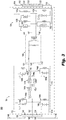
Fig. 3 is a detailed schematic view of the ESM ofFig. 1 , showing the circuit elements of the ESM assembly. - Reference will now be made to the drawings wherein like reference numerals identify similar structural features or aspects of the subject disclosure. For purposes of explanation and illustration, and not limitation, a partial view of an exemplary embodiment of an ESM assembly constructed in accordance with the disclosure is shown in
Fig. 1 and is designated generally byreference character 100. Other embodiments ofESM assembly 100 in accordance with the disclosure, or aspects thereof, are provided inFigs. 2-3 , as will be described. The systems and methods described herein can be used in air vehicles, though the present disclosure is not limited to aircraft, e.g. fixed wing aircraft. It is also contemplated that the systems and methods described herein can be used in ground vehicles, e.g. ground vehicles having a high-voltage bus, such as +/- 300V. - Referring to
Fig. 1 , anelectrical system 10, e.g., an aircraft electrical system is shown.Electrical system 10 includes agenerator 12, apower bus 14, andelectrical loads 16.Generator 12 is operably associated with anengine 18, e.g., an aircraft main engine or auxiliary power unit, and is arranged to provide a flow ofelectrical power 20 topower bus 14.Power bus 14 is connected to respective power-consumingdevices 16 to provideelectrical power 20 toelectrical loads 16.ESM assembly 100 is disposed in electrical communication withpower bus 14 and is configured to and adapted to be charged by and discharged frompower bus 14. Although an aircraft electrical system is shown and described herein it is to be understood and appreciated that other types of electrical systems can also benefit from the present disclosure. - With reference now to
Figs. 1 and2 , asystem architecture 101 includesESM assembly 100 andpower bus 14. As shown and described herein,power bus 14 is a DC power bus and includes apositive rail 22, aneutral rail 24, and anegative rail 26.Positive rail 22,neutral rail 24, andnegative rail 26 connect one or more ofelectrical loads 16 withgenerator 12 to provideDC power 20. It is contemplated thatDC power bus 14 is a high voltage DC power bus, e.g., +/-270 volts or higher (e.g., +/- 300 volts for ground vehicles), with the positive voltage provided onpositive rail 22, the negative voltage provided onnegative rail 26, andneutral rail 24 being 0 volts. - As shown in
Figs. 2-3 ,ESM assembly 100 includes an energy storage module (ESM) 102, a multi-level dual active bridge (ML-DAB) 104, and apower filter 106.ESM assembly 100 is coupled topositive rail 22,neutral rail 24 andnegative rail 26.Power filter 106 is connected between ML-DAB andDC bus 14. Multi-level refers to the different voltage levels in a system. In this case, the three levels are -270V (at positive negative converter conductor 114), 0V (at neutral conductor 107), and +270V (at positive output converter conductor 112). Those skilled in the art will readily appreciate that there can be more levels and those levels do not have to correspond to these values. However, for aircraft applications, 270V is typically the upper voltage limit due to corona (arcing that can occur at altitude due to low air density reducing dielectric resistance). Dual active refers to having both sides of the converter (high voltage side 130 and low voltage side 134) being actively controlled. In this case, both sides are active in order to achieve soft-switching (makes unit more efficient). With single active control, only one side would be actively controlled and the other side would passively rectify. - More particularly, a filter conductor of
power filter 106 is connected topositive rail 22 by apositive filter lead 108 and another conductor ofpower filter 106 is connected toneutral rail 24 by aneutral filter lead 110.Filter lead 110 is coupled via aresistor 111 toneutral rail 24.Resistor 111 can be a high impedance resistor to ensure that power does not goneutral rail 24 and back into thegenerator 12. Whileresistor 111 is depicted onneutral filter lead 110 outside ofpower filter 106, those skilled in the art will readily appreciate thatresistor 111 could be positioned on thelead 110 withinpower filter 106.Power filter 106 is connected tonegative rail 26 by anegative filter lead 105. Aconverter conductor 112 of ML-DAB 104 is connected to a node (shown inFig. 3 as node 148) ofpower filter 106, aneutral converter conductor 107 of ML-DAB is connected to anode 109 ofpower filter 106, and aconverter conductor 114 of ML-DAB 104 is connected to a node (shown inFig. 3 as node 158) ofpower filter 106. - With reference now to
Fig. 3 ,ESM 102 includes anenergy source 132. ML-DAB 104 is connected toenergy source 132 to source current therefrom, or send current thereto, or both. ML-DAB 104 includes a bi-directional DC/AC converter 134. DC/AC converter 134 includesconductors ESM 102 andenergy source 132. ML-DAB 104 includes abi-directional isolation transformer 140. Alow voltage side 141 ofisolation transformer 140 is connected to bi-directional DC/AC converter 134 throughconductors DAB 104 includes a second bi-directional DC/AC converter 130 connected to ahigh voltage side 143 ofisolation transformer 140 throughconductors energy source 132 can be a fuel cell, battery, and/or an ultracapacitor strung together in series or on their own. - As shown in
Figs. 2-3 ,conductor 116 of ML-DAB 104, e.g. a positive terminal conductor, is connected topositive ESM terminal 126. A singular negative ESM terminal (shown inFig. 3 as negative ESM terminal 122) is connected toconductor 118, e.g. anegative terminal conductor 118.Energy source 132 is connected betweennegative ESM terminal 122 andpositive ESM terminal 126. Those skilled in the art will readily appreciate that more than oneenergy source 132 can be used.Multiple energy sources 132 are connected in series with one another in a string betweennegative ESM terminal 122 andpositive ESM terminal 126. In this respect,energy cells 132 can be mid-size ultracapacitors, e.g., capacitors having a capacitance in the range of 1 farad to about 500 farads. Notably, the ESM can be at either a lower or a higher voltage thanpower bus 14.ESM 102 can include, for example and without limitation, a battery or an ultracapacitor, or a hybrid of energy storage technologies - With continued reference to
Figs. 2-3 , the ML-DAB allows for asingle ESM assembly 100 with a single larger battery to achieve a split bus output (as opposed to requiring two separate ESM architectures, e.g. one for positive and one for negative). Parallel stages of thesingle ESM assembly 100 can be used to achieve the desired power rating. As shown inFig. 2 , asecond ESM assembly 100b, exact toESM assembly 100, can be used in parallel withESM assembly 100 in order to achieve higher power and/or energy storage requirements. This allows for a single design to be used to meet a wide range of applications. Those skilled in the art will readily appreciate that, in some embodiments,transformer 140 can have multiple inputs to provide parallel operation. In other words, transformer would have another set ofconnectors AC converter 134, and another ESM,e.g. ESM 132. ESM architectures that require two separate ESM assemblies for split bus connection tend to occupy more space, have increased weight, and have complex interface systems, the embodiments of the present disclosure provide an ESM assembly with reduced weight, volume and complexity. - With continued reference to
Fig. 3 , each of first phase solid-state switch devices 142a-142d is provided with adiode 143 disposed in parallel with its respectivecorresponding switch 142a-142d. Solid-state switch devices state switch devices state switch devices 144a-144f is provided with adiode 145 disposed in parallel with the respectivecorresponding switch 144a-144f. Solid-state switch devices state switch devices state switch devices AC converter 130 is a t-type dual active bridge. T-type refers to the configuration of switches on the right side of 130 made up ofswitches - The second phase, e.g. second bi-directional DC/
AC converter 130, includes three legs. A first leg connects betweenisolation transformer 140 and positiveoutput converter conductor 112 atnode 146a, and includes first and second solid-state switch devices isolation transformer 140 andnegative converter conductor 114 atnode 146b, and includes first and second solid-state switch devices isolation transformer 140 andneutral rail 24 atnode 146c, and includes first and second solid-state switch devices Isolation transformer 140 is connected by parallel couplings tonodes - With reference to
Figs. 2-3 , a method of regulating voltage on a DC bus, e.g.,DC bus 14, can be, for example, a proportional integral controller method with a feedforward term on the bus current. It is contemplated that there can be a deadzone on the output when it is near zero to keep the system from running all the time. The method includes comparing voltage on the DC bus to a DC bus voltage target. When a determination is made that the bus voltage is above the voltage target by a first predetermined amount, an absorb mode is entered in which a command is generated to control current to be absorbed by an ESM, such asESM 102. Causing the current to be absorbed by the ESM can be performed, for example, based on a difference between the bus voltage and the target voltage. The absorbing of current can continue until the bus voltage returns within a predetermined range defined by the first predetermined amount and the voltage target or until the ESM becomes fully charged and is forced to stop charging. - When the bus voltage comparison indicates that the bus voltage is not above the voltage target by the first predetermined amount, a determination is made as to whether the bus voltage is below the target voltage by a second predetermined amount. If the comparison indicates that the bus voltage is not below the voltage target by the second predetermined amount, then bus voltage monitoring continues. When the comparison indicates that the bus voltage is below the voltage target by the second predetermined amount, a source mode is entered in which a command is generated to source current from the ESM, e.g., via the
energy source 132. Sourcing the current from the ESM can be performed, for example, based on a difference between the bus voltage and the target voltage. The sourcing of the current can continue until the bus voltage returns to within a predetermined range defined by the first and second predetermined amounts. - The methods and systems of the present disclosure, as described above and shown in the drawings provide for ESM architectures with superior properties including lighter weight and reduced interface complexity. While the apparatus and methods of the subject disclosure have been shown and described with reference to certain embodiments, those skilled in the art will readily appreciate that change and/or modifications may be made thereto without departing from the scope of the subject disclosure.
Claims (15)
- An energy storage module (ESM) assembly (100), comprising:an ESM (102) having an energy source; anda multi-level dual active bridge (ML-DAB) (104) connected to the energy source to source current therefrom, or send current thereto, or both.
- The ESM assembly as recited in claim 1, wherein the ML-DAB (104) includes a bi-directional DC/AC converter (134), wherein the DC/AC converter (134) includes a conductor (116, 118) connected to the energy source.
- The ESM assembly as recited in claim 2, wherein the ML-DAB (104) includes a bi-directional isolation transformer (140) connected to the bi-directional DC/AC converter (134).
- The ESM assembly as recited in claim 3, wherein the ML-DAB (104) includes a second bi-directional DC/AC converter connected to the isolation transformer.
- The ESM assembly as recited in claim 4, wherein the second bi-directional DC/AC converter is a t-type dual active bridge.
- The ESM assembly as recited in any preceding claim, wherein the ESM assembly (100) is configured and adapted to be electrically coupled to a negative rail (26), a positive rail (22) and a neutral rail (24) of a DC bus (14).
- The ESM assembly as recited in any preceding claim, further comprising a power filter (106) connected to the ML-DAB.
- The ESM assembly as recited in claim 7, wherein the power filter (106) includes a negative lead, a positive lead and neutral filter lead extending therefrom configured and adapted to be electrically coupled to a negative rail (26), a positive rail (22) and a neutral rail (24), respectively, of a DC bus.
- The ESM assembly as recited in any preceding claim, wherein the energy source includes at least one of a fuel cell, battery, or ultracapacitor.
- A system architecture, comprising:an ESM assembly (100) as recited in any preceding claim; anda DC bus (106) connected to the ESM assembly (100).
- The system architecture as recited in claim 10, wherein the ESM assembly (100) includes a power filter (106) coupled between the ML-DAB (104) and the DC bus (14).
- The system architecture as recited in claim 11, wherein the power filter (106) includes a negative lead, a positive lead and neutral filter lead extending therefrom electrically coupled to a negative rail, a positive rail and a neutral rail, respectively, of the DC bus.
- The system architecture as recited in claim 10, wherein the ESM (102) includes at least one of a fuel cell, battery, or ultracapacitor.
- The system architecture as recited in claim 10, wherein the ESM assembly (100) is a first ESM assembly, the system further comprising a second ESM assembly in parallel with the first ESM assembly.
- The system architecture as recited in claim 14, wherein the second ESM assembly is electrically coupled to a negative rail, a positive rail and a neutral rail of the DC bus.
Applications Claiming Priority (1)
| Application Number | Priority Date | Filing Date | Title |
|---|---|---|---|
| US16/277,677 US10868475B2 (en) | 2019-02-15 | 2019-02-15 | Dual active bridge energy storage module systems |
Publications (1)
| Publication Number | Publication Date |
|---|---|
| EP3696931A1 true EP3696931A1 (en) | 2020-08-19 |
Family
ID=68653381
Family Applications (1)
| Application Number | Title | Priority Date | Filing Date |
|---|---|---|---|
| EP19210711.8A Pending EP3696931A1 (en) | 2019-02-15 | 2019-11-21 | Dual active bridge energy storage module systems |
Country Status (2)
| Country | Link |
|---|---|
| US (1) | US10868475B2 (en) |
| EP (1) | EP3696931A1 (en) |
Cited By (2)
| Publication number | Priority date | Publication date | Assignee | Title |
|---|---|---|---|---|
| EP4092898A1 (en) * | 2021-05-21 | 2022-11-23 | Hamilton Sundstrand Corporation | Modular solid-state power converter and fault protector |
| EP4287475A4 (en) * | 2021-03-05 | 2024-02-28 | Huawei Digital Power Technologies Co., Ltd. | SEMICONDUCTOR TRANSFORMER, POWER SUPPLY DEVICE AND DATA CENTER |
Family Cites Families (5)
| Publication number | Priority date | Publication date | Assignee | Title |
|---|---|---|---|---|
| US8395280B2 (en) | 2010-02-16 | 2013-03-12 | Infineon Technologies Ag | Circuit arrangement including a multi-level converter |
| US8970161B1 (en) | 2011-06-29 | 2015-03-03 | Carlos Cuadros | Modulation control scheme for power converters in photovoltaic system charge controllers |
| US9893633B1 (en) * | 2016-03-23 | 2018-02-13 | The Florida State University Research Foundation, Inc. | Modular multilevel DC-DC converter and associated method of use |
| US10245961B2 (en) | 2016-06-01 | 2019-04-02 | Current Ways, Inc. | Inverter-charger combination |
| EP3291432B1 (en) | 2016-09-06 | 2020-02-19 | Siemens Aktiengesellschaft | Dual-active-bridge with modular multilevel bridges |
-
2019
- 2019-02-15 US US16/277,677 patent/US10868475B2/en active Active
- 2019-11-21 EP EP19210711.8A patent/EP3696931A1/en active Pending
Non-Patent Citations (2)
| Title |
|---|
| GEORGIOS E. SFAKIANAKIS ET AL: "Charge-based ZVS modulation of a 3-5 level bidirectional dual active bridge DC-DC converter", 2016 IEEE ENERGY CONVERSION CONGRESS AND EXPOSITION (ECCE), 1 September 2016 (2016-09-01), pages 1 - 10, XP055668754, ISBN: 978-1-5090-0737-0, DOI: 10.1109/ECCE.2016.7854914 * |
| RALPH M. BURKART ET AL: "Comparative $\eta$- $\rho$- $\sigma$ Pareto Optimization of Si and SiC Multilevel Dual-Active-Bridge Topologies With Wide Input Voltage Range", IEEE TRANSACTIONS ON POWER ELECTRONICS, vol. 32, no. 7, 1 July 2017 (2017-07-01), USA, pages 5258 - 5270, XP055668749, ISSN: 0885-8993, DOI: 10.1109/TPEL.2016.2614139 * |
Cited By (4)
| Publication number | Priority date | Publication date | Assignee | Title |
|---|---|---|---|---|
| EP4287475A4 (en) * | 2021-03-05 | 2024-02-28 | Huawei Digital Power Technologies Co., Ltd. | SEMICONDUCTOR TRANSFORMER, POWER SUPPLY DEVICE AND DATA CENTER |
| US12609601B2 (en) | 2021-03-05 | 2026-04-21 | Huawei Digital Power Technologies Co., Ltd. | Solid-state transformer, power supply device, and data center |
| EP4092898A1 (en) * | 2021-05-21 | 2022-11-23 | Hamilton Sundstrand Corporation | Modular solid-state power converter and fault protector |
| US11728738B2 (en) | 2021-05-21 | 2023-08-15 | Hamilton Sundstrand Corporation | Modular solid-state power converter and fault protector |
Also Published As
| Publication number | Publication date |
|---|---|
| US20200266728A1 (en) | 2020-08-20 |
| US10868475B2 (en) | 2020-12-15 |
Similar Documents
| Publication | Publication Date | Title |
|---|---|---|
| EP3567711B1 (en) | Module of suppressing inrush current, method of controlling the same and on-board bidirectional charger using the same | |
| US8227939B2 (en) | Reconfigurable multi-cell power converter | |
| US6917181B2 (en) | Power supply unit, distributed power supply system and electric vehicle loaded therewith | |
| US20130285615A1 (en) | Module for converting voltage between a high-voltage electrical network of an aircraft and an energy storage element | |
| US11791628B2 (en) | SST system with multiple LVDC outputs | |
| EP4030610A1 (en) | Power conversion system and method of controlling the same | |
| EP3322059B1 (en) | Solar powered spacecraft power system | |
| CN107707011A (en) | A kind of Helios supplies power distribution equipment | |
| CN111725981A (en) | A photovoltaic inverter, photovoltaic system and discharge control method | |
| EP3696931A1 (en) | Dual active bridge energy storage module systems | |
| EP3644470B1 (en) | Energy storage modules with parallel energy storage module architectures | |
| CN115459242A (en) | Multi-power supply module series-parallel control device and control method for realizing automatic hot swap | |
| EP4425729A1 (en) | Vehicle power supply system and vehicle comprising same | |
| CN119968748A (en) | DC transformer arrangement, energy supply system and method for discharging an intermediate circuit capacitor | |
| RU2478537C2 (en) | Method of spacecraft manufacture | |
| Lücken et al. | Integration scenarios to improve fuel cell dynamics for modern aircraft application | |
| EP4498551A1 (en) | Multilane power distribution system | |
| Buticchi et al. | A Quadruple Active Bridge converter as the storage interface in the more electric aircraft | |
| EP4498552A1 (en) | Multilane power distribution system | |
| CN224218118U (en) | A charging module and charging system | |
| CN120171356B (en) | Charging and discharging control system and charging pile | |
| CN114024447A (en) | Auxiliary power supply system and power electronic converter system | |
| CN121710505A (en) | Internal power supply unit for motor controller, motor controller and electric drive system | |
| CN116520931A (en) | A solar cell array power regulation circuit |
Legal Events
| Date | Code | Title | Description |
|---|---|---|---|
| PUAI | Public reference made under article 153(3) epc to a published international application that has entered the european phase |
Free format text: ORIGINAL CODE: 0009012 |
|
| STAA | Information on the status of an ep patent application or granted ep patent |
Free format text: STATUS: THE APPLICATION HAS BEEN PUBLISHED |
|
| AK | Designated contracting states |
Kind code of ref document: A1 Designated state(s): AL AT BE BG CH CY CZ DE DK EE ES FI FR GB GR HR HU IE IS IT LI LT LU LV MC MK MT NL NO PL PT RO RS SE SI SK SM TR |
|
| AX | Request for extension of the european patent |
Extension state: BA ME |
|
| RIN1 | Information on inventor provided before grant (corrected) |
Inventor name: WILHIDE, MATTHEW L. Inventor name: FENG, FRANK Z. |
|
| STAA | Information on the status of an ep patent application or granted ep patent |
Free format text: STATUS: REQUEST FOR EXAMINATION WAS MADE |
|
| 17P | Request for examination filed |
Effective date: 20210219 |
|
| RBV | Designated contracting states (corrected) |
Designated state(s): AL AT BE BG CH CY CZ DE DK EE ES FI FR GB GR HR HU IE IS IT LI LT LU LV MC MK MT NL NO PL PT RO RS SE SI SK SM TR |
|
| STAA | Information on the status of an ep patent application or granted ep patent |
Free format text: STATUS: EXAMINATION IS IN PROGRESS |
|
| 17Q | First examination report despatched |
Effective date: 20220114 |
|
| GRAP | Despatch of communication of intention to grant a patent |
Free format text: ORIGINAL CODE: EPIDOSNIGR1 |
|
| STAA | Information on the status of an ep patent application or granted ep patent |
Free format text: STATUS: GRANT OF PATENT IS INTENDED |
|
| RIC1 | Information provided on ipc code assigned before grant |
Ipc: H02M 7/487 20070101ALI20250320BHEP Ipc: H02M 3/335 20060101ALI20250320BHEP Ipc: B60R 16/03 20060101ALI20250320BHEP Ipc: H02J 7/34 20060101ALI20250320BHEP Ipc: H02J 1/14 20060101ALI20250320BHEP Ipc: H02J 1/10 20060101ALI20250320BHEP Ipc: H02J 1/08 20060101AFI20250320BHEP |
|
| INTG | Intention to grant announced |
Effective date: 20250411 |
|
| GRAJ | Information related to disapproval of communication of intention to grant by the applicant or resumption of examination proceedings by the epo deleted |
Free format text: ORIGINAL CODE: EPIDOSDIGR1 |
|
| STAA | Information on the status of an ep patent application or granted ep patent |
Free format text: STATUS: EXAMINATION IS IN PROGRESS |
|
| INTC | Intention to grant announced (deleted) |