EP3696796A1 - Replacement device, replacement method, and program - Google Patents
Replacement device, replacement method, and program Download PDFInfo
- Publication number
- EP3696796A1 EP3696796A1 EP18865871.0A EP18865871A EP3696796A1 EP 3696796 A1 EP3696796 A1 EP 3696796A1 EP 18865871 A EP18865871 A EP 18865871A EP 3696796 A1 EP3696796 A1 EP 3696796A1
- Authority
- EP
- European Patent Office
- Prior art keywords
- permutation
- integer
- elements
- sequence
- buffer
- Prior art date
- Legal status (The legal status is an assumption and is not a legal conclusion. Google has not performed a legal analysis and makes no representation as to the accuracy of the status listed.)
- Granted
Links
Images



Classifications
-
- G—PHYSICS
- G06—COMPUTING OR CALCULATING; COUNTING
- G06F—ELECTRIC DIGITAL DATA PROCESSING
- G06F12/00—Accessing, addressing or allocating within memory systems or architectures
- G06F12/02—Addressing or allocation; Relocation
- G06F12/08—Addressing or allocation; Relocation in hierarchically structured memory systems, e.g. virtual memory systems
- G06F12/0802—Addressing of a memory level in which the access to the desired data or data block requires associative addressing means, e.g. caches
-
- H—ELECTRICITY
- H04—ELECTRIC COMMUNICATION TECHNIQUE
- H04L—TRANSMISSION OF DIGITAL INFORMATION, e.g. TELEGRAPHIC COMMUNICATION
- H04L9/00—Cryptographic mechanisms or cryptographic arrangements for secret or secure communications; Network security protocols
- H04L9/08—Key distribution or management, e.g. generation, sharing or updating, of cryptographic keys or passwords
- H04L9/0861—Generation of secret information including derivation or calculation of cryptographic keys or passwords
-
- G—PHYSICS
- G06—COMPUTING OR CALCULATING; COUNTING
- G06F—ELECTRIC DIGITAL DATA PROCESSING
- G06F12/00—Accessing, addressing or allocating within memory systems or architectures
- G06F12/02—Addressing or allocation; Relocation
- G06F12/08—Addressing or allocation; Relocation in hierarchically structured memory systems, e.g. virtual memory systems
- G06F12/10—Address translation
- G06F12/109—Address translation for multiple virtual address spaces, e.g. segmentation
-
- G—PHYSICS
- G06—COMPUTING OR CALCULATING; COUNTING
- G06F—ELECTRIC DIGITAL DATA PROCESSING
- G06F7/00—Methods or arrangements for processing data by operating upon the order or content of the data handled
- G06F7/76—Arrangements for rearranging, permuting or selecting data according to predetermined rules, independently of the content of the data
- G06F7/766—Generation of all possible permutations
-
- G—PHYSICS
- G09—EDUCATION; CRYPTOGRAPHY; DISPLAY; ADVERTISING; SEALS
- G09C—CIPHERING OR DECIPHERING APPARATUS FOR CRYPTOGRAPHIC OR OTHER PURPOSES INVOLVING THE NEED FOR SECRECY
- G09C1/00—Apparatus or methods whereby a given sequence of signs, e.g. an intelligible text, is transformed into an unintelligible sequence of signs by transposing the signs or groups of signs or by replacing them by others according to a predetermined system
-
- G—PHYSICS
- G06—COMPUTING OR CALCULATING; COUNTING
- G06F—ELECTRIC DIGITAL DATA PROCESSING
- G06F2212/00—Indexing scheme relating to accessing, addressing or allocation within memory systems or architectures
- G06F2212/46—Caching storage objects of specific type in disk cache
- G06F2212/462—Track or segment
-
- H—ELECTRICITY
- H04—ELECTRIC COMMUNICATION TECHNIQUE
- H04L—TRANSMISSION OF DIGITAL INFORMATION, e.g. TELEGRAPHIC COMMUNICATION
- H04L2209/00—Additional information or applications relating to cryptographic mechanisms or cryptographic arrangements for secret or secure communication H04L9/00
- H04L2209/12—Details relating to cryptographic hardware or logic circuitry
- H04L2209/122—Hardware reduction or efficient architectures
-
- Y—GENERAL TAGGING OF NEW TECHNOLOGICAL DEVELOPMENTS; GENERAL TAGGING OF CROSS-SECTIONAL TECHNOLOGIES SPANNING OVER SEVERAL SECTIONS OF THE IPC; TECHNICAL SUBJECTS COVERED BY FORMER USPC CROSS-REFERENCE ART COLLECTIONS [XRACs] AND DIGESTS
- Y02—TECHNOLOGIES OR APPLICATIONS FOR MITIGATION OR ADAPTATION AGAINST CLIMATE CHANGE
- Y02D—CLIMATE CHANGE MITIGATION TECHNOLOGIES IN INFORMATION AND COMMUNICATION TECHNOLOGIES [ICT], I.E. INFORMATION AND COMMUNICATION TECHNOLOGIES AIMING AT THE REDUCTION OF THEIR OWN ENERGY USE
- Y02D10/00—Energy efficient computing, e.g. low power processors, power management or thermal management
Definitions
- the present invention relates to a technique for performing permutation processing at high speed.
- Permutation is one of basic data processing techniques used in a computer and the like and has found applications in various settings.
- Conventional permutation techniques include obvious permutation which moves data in sequence to locations described in permutation information and Fisher-Yates algorithm for randomly shuffling an array (see Non-patent Literature 1, for instance).
- Non-patent Literature 1 Fisher, Ronald A., Yates, Frank, "Statistical tables for biological, agricultural and medical research", Oliver & Boyd, pp. 26-27, 1938 .
- IO accesses take place as random accesses when performing permutation processing.
- accesses to a non-cache memory occur when target data is larger than a cache memory.
- an access speed differs by an order of magnitude or more between a cache memory and a non-cache memory and by an order of magnitude or more between sequential access and random access.
- the conventional permutation techniques have the problem in that random accesses to a non-cache memory occur and it slows the processing.
- an object of the invention is to provide a permutation technique capable of performing permutation processing at higher speed than the conventional techniques.
- a first aspect of the present invention provides a permutation apparatus, where D is a predetermined number of segmentations, a ⁇ is a vector of length m, b ⁇ is a sequence of values less than D representing allocation destinations in a buffer, x ⁇ is a sequence of values representing permutation destinations within the respective allocation destinations, d ⁇ is a vector representing a buffer of length m, i is each integer equal to or greater than 0 and less than D, j is each integer equal to or greater than 0 and less than m, Si is a start position corresponding to an i-th allocation destination, and Ni is the number of elements to be contained in the i-th allocation destination.
- the permutation apparatus includes: an initial position setting unit that, for each integer i, sets the start position Si into a value Pi indicating a position within processing corresponding to the i-th allocation destination; a rearrangement unit that, for each integer j, sets a j-th element a j of the vector a ⁇ into a P b_j -th element d P_b_j in the buffer d ⁇ ; and a permutation execution unit that, for each integer i, generates Ni elements cs_i, ..., c S_i+N_i-1 starting at an Si-th element of an output vector c ⁇ by executing an arbitrary inverse permutation algorithm on Ni elements ds_i, ..., d S_i+N_i-1 starting at an Si-th element in the buffer d ⁇ using N i elements starting at an Si-th element of the sequence x ⁇ .
- a second aspect of the present invention provides a permutation apparatus, where D is a predetermined number of segmentations, a ⁇ is a vector of length m, b ⁇ is a sequence of values less than D representing allocation destinations in a buffer, x ⁇ is a sequence of values representing permutation destinations within the respective allocation destinations, d ⁇ is a vector representing a buffer of length m, i is each integer equal to or greater than 0 and less than D, j is each integer equal to or greater than 0 and less than m, Si is a start position corresponding to an i-th allocation destination, and N i is the number of elements to be contained in the i-th allocation destination.
- the permutation apparatus includes: a permutation execution unit that, for each integer i, sets Ni elements ds_i, ..., d S_i+N-i-1 starting at an Si-th element in the buffer d ⁇ by executing an arbitrary permutation algorithm on N i elements starting at an Si-th element of the vector a ⁇ using N i elements starting at an Si-th element of the sequence x ⁇ ; an initial position setting unit that, for each integer i, sets the start position Si into a value Pi indicating a position within processing corresponding to the i-th allocation destination; and a rearrangement unit that, for each integer j, sets a P b_j -th element d P_b_j in the buffer d ⁇ into a j-th element c j of an output vector c ⁇ .
- the present invention can perform permutation process at higher speed than the conventional techniques because it can reduce random accesses to a non-cache memory by previously performing processing for allocating permutation target data across buffers that fit in a cache.
- x ⁇ used herein represents vector x or sequence x.
- a subscript attached to the letter immediately preceding " ⁇ " represents an element number within the vector or sequence.
- x i represents the i-th element of vector x ⁇ .
- a b_c means that b c is attached to A as a subscript.
- a B_c_d means that B c_d is attached to A as a subscript.
- a permutation technique of the present invention executes processing for coarsely allocating the data into D ( ⁇ 2) buffers that fit in a cache, E ( ⁇ 1) times (this is sequential access processing to a non-cache memory), and switches to general permutation involving random accesses when a cache hit ratio with m/D E pieces of data has become sufficiently high (this is random access processing to the cache memory), thereby reducing random accesses to the non-cache memory, which is slow, to achieve high speed permutation.
- D is referred to as the number of segmentations and E is referred to as recursion depth.
- D buffers that fit in a cache does not mean that the size of each one of the D buffers is equal to or less than the size of the cache memory.
- a caching mechanism stores data around the area into the cache. Assuming that the unit to store is X and the cache size is C, the cache will always hit if the number of locations to be accessed is limited to about C/X. Also, if sequential access is made at each of the D locations, a cache miss only occurs when sequential access to a location ends up in an area that has not been cached, in which case the speed will be the same as that of a general sequential access. Accordingly, it is desirable that D is a value on the order of C/X.
- the speed differs by an order of magnitude or more between a cache memory and a non-cache memory and by an order of magnitude or more between sequential access and random access.
- the present invention which performs several sequential accesses to a non-cache memory and one random access to a cache memory, is faster than a conventional technique which performs one random access to a non-cache memory. For example, when there are a million pieces of 4-byte data and the cache memory is 256 kilobytes and the unit to store in the cache is 16 kilobytes, the data size will be 4 megabytes and the cache hit ratio will be around 8%.
- the present invention is also applicable to non-random permutation.
- a general permutation that has been given in conformance to the processing procedure of the present invention is converted in format into a sequence of values representing allocation destinations and a sequence of values representing permutation destinations within the allocation destinations.
- Ni and Si when Scheme 2 is performed in combination with Scheme 3 or 4, Ni and Si may be set as follows.
- N i q+(i ⁇ r?1:0)
- Si iq+min(r, i)
- E ⁇ 2 the arbitrary inverse permutation algorithm executed at Step 7 of Scheme 3 may be recursively processed on Scheme 3 itself.
- Steps 6 and 7 can be processed in parallel.
- Steps 2 and 3 can be processed in parallel.
- iterations of Steps 5 to 7 cannot be processed in parallel.
- the left member and the right member separated by v are exclusive, and the number of elements to be stored in the k-th buffer is the sum of the number of j's that satisfy the left member and the number of j's that satisfy the right member.
- the number of j's is q+1 when k ⁇ r and is q when k ⁇ r.
- a first embodiment of the present invention is a permutation apparatus and method that execute the random permutation shown in Scheme 1.
- a permutation apparatus 1 of the first embodiment includes an allocation destination determination unit 11, a number-of-elements determination unit 12, a start position determination unit 13, an initial position setting unit 14, a rearrangement unit 15, and a permutation execution unit 16, as illustrated in Fig. 1 .
- the permutation method of the first embodiment is carried out.
- the permutation apparatus 1 is a special device configured by loading of a special program into a well-known or a dedicated computer having a central processing unit (CPU), main storage unit (random access memory: RAM), and the like, for example.
- the permutation apparatus 1 executes processing under control of the central processing unit, for example.
- Data input to the permutation apparatus 1 and data resulting from processing are stored in the main storage unit, for example, and the data stored in the main storage unit is read into the central processing unit and utilized for other processing as necessary.
- the processing components of the permutation apparatus 1 may be at least partially composed of hardware such as an integrated circuit.
- the random numbers b 0 , b 1 , ..., b m-1 are values representing the allocation destinations for allocating the elements a 0 , a 1 , ..., a m-1 of the vector a ⁇ to be permuted in the buffer.
- the number-of-elements determination unit 12 determines the number of elements N i for the i-th allocation destination by counting the number of occurrences of the integer i in the sequence b ⁇ .
- S 0 : 0.
- step S16 for each integer i equal to or greater than 0 and less than D, when E ⁇ 2, the permutation execution unit 16 recursively executes steps S11 to S16 with N i elements ds_i, ..., d S_i+N_i-1 starting at the Si-th element of the vector d ⁇ as the input vector and with the recursion depth E set as E-1.
- E 1
- a second embodiment of the present invention is a permutation apparatus and method that execute the inverse permutation shown in Scheme 3 using a sequence of values representing allocation destinations in the buffer and a sequence of values representing permutation destinations within the respective allocation destinations, which were generated through the format conversion shown in Scheme 2.
- a permutation apparatus 2 of the second embodiment includes a division unit 21, a number-of-elements determination unit 22, a start position determination unit 23, an allocation destination determination unit 24, a permutation generating unit 25, an initial position setting unit 31, a rearrangement unit 32, and a permutation execution unit 33, as illustrated in Fig. 3 .
- the permutation apparatus 2 performing the processing at each of the steps illustrated in Fig. 4 , the permutation method of the second embodiment is carried out.
- a third embodiment of the present invention is a permutation apparatus and method that execute the permutation shown in Scheme 4 using a sequence of values representing the allocation destinations in the buffer and a sequence of values representing permutation destinations within the respective allocation destinations, which were generated through the format conversion shown in Scheme 2.
- a permutation apparatus 3 of the third embodiment includes a division unit 21, a number-of-elements determination unit 22, a start position determination unit 23, an allocation destination determination unit 24, a permutation generating unit 25, a permutation execution unit 41, an initial position setting unit 42, and a rearrangement unit 43, as illustrated in Fig. 5 .
- the permutation method of the third embodiment is carried out.
- Processing at step S21 to step S25 is similar to the second embodiment.
- a fourth embodiment of the present invention is a permutation apparatus and method that handle two random permutations (b ⁇ , x ⁇ ) generated by Scheme 1 as a sequence of values representing allocation destinations in a buffer and a sequence of values representing permutation destinations within the respective allocation destinations and execute the inverse permutation shown in Scheme 3.
- a permutation apparatus 4 of the fourth embodiment includes an allocation destination determination unit 11, a number-of-elements determination unit 12, a start position determination unit 13, a permutation generating unit 17, an initial position setting unit 31, a rearrangement unit 32, and a permutation execution unit 33, as illustrated in Fig. 7 .
- the permutation method of the fourth embodiment is carried out.
- step S11 to step S13 is similar to the first embodiment.
- the permutation generating unit 17 generates m permutations ⁇ i utilizing an arbitrary inverse permutation algorithm for each integer i equal to or greater than 0 and less than D.
- a sequence of values generated by concatenating the permutations ⁇ i in sequential order is handled as a sequence of values x ⁇ representing permutation destinations within the respective allocation destinations.
- step S31 to step S33 is similar to the second embodiment.
- a fifth embodiment of the present invention is a permutation apparatus and method that handle two random permutations (b ⁇ , x ⁇ ) generated by Scheme 1 as a sequence of values representing allocation destinations in a buffer and a sequence of values representing permutation destinations within the respective allocation destinations and execute the permutation shown in Scheme 4.
- a permutation apparatus 5 of the fifth embodiment includes an allocation destination determination unit 11, a number-of-elements determination unit 12, a start position determination unit 13, a permutation generating unit 17, a permutation execution unit 41, an initial position setting unit 42, and a rearrangement unit 43, as illustrated in Fig. 9 .
- the permutation method of the fifth embodiment is carried out.
- Processing at step S11 to step S13 is similar to the fourth embodiment.
- Processing at step S17 is similar to the fourth embodiment.
- step S41 to step S43 is similar to the third embodiment.
- the random permutation can be undone.
- permutations ⁇ i that were generated during the execution of an arbitrary permutation algorithm are concatenated in sequential order to make a sequence x ⁇ of values representing permutation destinations within the respective allocation destinations, and using it with a sequence b ⁇ of values representing allocation destinations in the buffer that was generated when the permutation apparatus of the first embodiment was executed, the processing at steps S31 to S33 shown in the second and the fourth embodiments may be executed.
- the sequence b ⁇ of values representing allocation destinations in the buffer and the sequence x ⁇ of values representing permutation destinations within the allocation destination may be saved in a storage, not shown, in the permutation apparatus and read and utilized as necessary.
- the gist of the present invention is as follows.
- the present invention achieves permutation at high speed by making use of the fact that several sequential accesses and one random access to a cache is faster than random accesses to a non-cache memory despite an increase in the amount of processing and the fact that random accesses to several locations can be done at a similar speed to that of sequential access.
- the format conversion (Scheme 2) from a general permutation the present invention is designed such that elements are evenly allocated via several addition/subtraction and comparison operations, which are categorized as one of the fastest operations on modern computers, aside from one multiplication per element.
- E needs to be increased as the number of data increases in order to eliminate random accesses, the frequency of access itself conversely increases when E is increased; it is understood that there is an optimal value of E depending on the amount of data.
- the computer-readable recording medium may be any medium such as a magnetic recording device, an optical disk, a magneto-optical recording medium, and a semiconductor memory.
- Distribution of this program is implemented by sales, transfer, rental, and other transactions of a portable recording medium such as a DVD and a CD-ROM on which the program is recorded, for example. Furthermore, this program may be stored in a storage unit of a server computer and transferred from the server computer to other computers via a network so as to be distributed.
- a computer which executes such program first stores the program recorded in a portable recording medium or transferred from a server computer once in a storage unit thereof, for example.
- the computer reads out the program stored in the storage unit thereof and performs processing in accordance with the program thus read out.
- the computer may directly read out the program from a portable recording medium and perform processing in accordance with the program.
- the computer may sequentially perform processing in accordance with the received program.
- a configuration may be adopted in which the transfer of a program to the computer from the server computer is not performed and the above-described processing is executed by so-called application service provider (ASP)-type service by which the processing functions are implemented only by an instruction for execution thereof and result acquisition.
- ASP application service provider
- a program in this form includes information which is provided for processing performed by electronic calculation equipment and which is equivalent to a program (such as data which is not a direct instruction to the computer but has a property specifying the processing performed by the computer).
- the present apparatus is configured with a predetermined program executed on a computer.
- the present apparatus may be configured with at least part of these processing contents realized in a hardware manner.
Landscapes
- Engineering & Computer Science (AREA)
- Theoretical Computer Science (AREA)
- Physics & Mathematics (AREA)
- General Physics & Mathematics (AREA)
- General Engineering & Computer Science (AREA)
- Computer Security & Cryptography (AREA)
- Computer Networks & Wireless Communication (AREA)
- Signal Processing (AREA)
- Complex Calculations (AREA)
- Data Exchanges In Wide-Area Networks (AREA)
- Information Retrieval, Db Structures And Fs Structures Therefor (AREA)
Abstract
Description
- The present invention relates to a technique for performing permutation processing at high speed.
- Permutation is one of basic data processing techniques used in a computer and the like and has found applications in various settings. Conventional permutation techniques include obvious permutation which moves data in sequence to locations described in permutation information and Fisher-Yates algorithm for randomly shuffling an array (see Non-patent Literature 1, for instance).
- Non-patent Literature 1: Fisher, Ronald A., Yates, Frank, "Statistical tables for biological, agricultural and medical research", Oliver & Boyd, pp. 26-27, 1938.
- In the conventional permutation techniques, IO accesses take place as random accesses when performing permutation processing. In addition, accesses to a non-cache memory occur when target data is larger than a cache memory. Typically, an access speed differs by an order of magnitude or more between a cache memory and a non-cache memory and by an order of magnitude or more between sequential access and random access. Thus, when the target data is large, the conventional permutation techniques have the problem in that random accesses to a non-cache memory occur and it slows the processing.
- In view of the foregoing, an object of the invention is to provide a permutation technique capable of performing permutation processing at higher speed than the conventional techniques.
- To solve the above-described problem, a first aspect of the present invention provides a permutation apparatus, where D is a predetermined number of segmentations, a→ is a vector of length m, b→ is a sequence of values less than D representing allocation destinations in a buffer, x→ is a sequence of values representing permutation destinations within the respective allocation destinations, d→ is a vector representing a buffer of length m, i is each integer equal to or greater than 0 and less than D, j is each integer equal to or greater than 0 and less than m, Si is a start position corresponding to an i-th allocation destination, and Ni is the number of elements to be contained in the i-th allocation destination. The permutation apparatus includes: an initial position setting unit that, for each integer i, sets the start position Si into a value Pi indicating a position within processing corresponding to the i-th allocation destination; a rearrangement unit that, for each integer j, sets a j-th element aj of the vector a→ into a Pb_j-th element dP_b_j in the buffer d→; and a permutation execution unit that, for each integer i, generates Ni elements cs_i, ..., cS_i+N_i-1 starting at an Si-th element of an output vector c→ by executing an arbitrary inverse permutation algorithm on Ni elements ds_i, ..., dS_i+N_i-1 starting at an Si-th element in the buffer d→ using Ni elements starting at an Si-th element of the sequence x→.
- To attain the object, a second aspect of the present invention provides a permutation apparatus, where D is a predetermined number of segmentations, a→ is a vector of length m, b→ is a sequence of values less than D representing allocation destinations in a buffer, x→ is a sequence of values representing permutation destinations within the respective allocation destinations, d→ is a vector representing a buffer of length m, i is each integer equal to or greater than 0 and less than D, j is each integer equal to or greater than 0 and less than m, Si is a start position corresponding to an i-th allocation destination, and Ni is the number of elements to be contained in the i-th allocation destination. The permutation apparatus includes: a permutation execution unit that, for each integer i, sets Ni elements ds_i, ..., dS_i+N-i-1 starting at an Si-th element in the buffer d→ by executing an arbitrary permutation algorithm on Ni elements starting at an Si-th element of the vector a→ using Ni elements starting at an Si-th element of the sequence x→; an initial position setting unit that, for each integer i, sets the start position Si into a value Pi indicating a position within processing corresponding to the i-th allocation destination; and a rearrangement unit that, for each integer j, sets a Pb_j-th element dP_b_j in the buffer d→ into a j-th element cj of an output vector c→.
- The present invention can perform permutation process at higher speed than the conventional techniques because it can reduce random accesses to a non-cache memory by previously performing processing for allocating permutation target data across buffers that fit in a cache.
-
-
Fig. 1 illustrates a functional configuration of a permutation apparatus according to a first embodiment. -
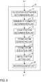
Fig. 2 illustrates a processing procedure of a permutation method according to the first embodiment. -
Fig. 3 illustrates a functional configuration of a permutation apparatus according to a second embodiment. -
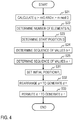
Fig. 4 illustrates a processing procedure of a permutation method according to the second embodiment. -
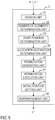
Fig. 5 illustrates a functional configuration of a permutation apparatus according to a third embodiment. -
Fig. 6 illustrates a processing procedure of a permutation method according to the third embodiment. -
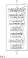
Fig. 7 illustrates a functional configuration of a permutation apparatus according to a fourth embodiment. -
Fig. 8 illustrates a processing procedure of a permutation method according to the fourth embodiment. -
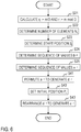
Fig. 9 illustrates a functional configuration of a permutation apparatus according to a fifth embodiment. -
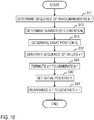
Fig. 10 illustrates a processing procedure of a permutation method according to the fifth embodiment. - "x→" used herein represents vector x or sequence x. A subscript attached to the letter immediately preceding "→" represents an element number within the vector or sequence. For example, "xi" represents the i-th element of vector x→.
- The symbol "_" used in a subscript means that the immediately following letters are subscripts. For example, Ab_c means that bc is attached to A as a subscript. Likewise, AB_c_d means that Bc_d is attached to A as a subscript.
- When permuting m (≥ 2) pieces of data, a permutation technique of the present invention executes processing for coarsely allocating the data into D (≥ 2) buffers that fit in a cache, E (≥ 1) times (this is sequential access processing to a non-cache memory), and switches to general permutation involving random accesses when a cache hit ratio with m/DE pieces of data has become sufficiently high (this is random access processing to the cache memory), thereby reducing random accesses to the non-cache memory, which is slow, to achieve high speed permutation. Hereinafter, D is referred to as the number of segmentations and E is referred to as recursion depth.
- "D buffers that fit in a cache" does not mean that the size of each one of the D buffers is equal to or less than the size of the cache memory. When a program accesses a certain storage area, a caching mechanism stores data around the area into the cache. Assuming that the unit to store is X and the cache size is C, the cache will always hit if the number of locations to be accessed is limited to about C/X. Also, if sequential access is made at each of the D locations, a cache miss only occurs when sequential access to a location ends up in an area that has not been cached, in which case the speed will be the same as that of a general sequential access. Accordingly, it is desirable that D is a value on the order of C/X.
- As mentioned above, the speed differs by an order of magnitude or more between a cache memory and a non-cache memory and by an order of magnitude or more between sequential access and random access. Thus, the present invention, which performs several sequential accesses to a non-cache memory and one random access to a cache memory, is faster than a conventional technique which performs one random access to a non-cache memory. For example, when there are a million pieces of 4-byte data and the cache memory is 256 kilobytes and the unit to store in the cache is 16 kilobytes, the data size will be 4 megabytes and the cache hit ratio will be around 8%. By contrast, when permutation of the present invention is performed with the number of segmentations D of 16 and the recursion depth E of 1, the data can be segmented into 16 portions each having 256 kilobytes through processing equivalent to a single sequential access, and the remaining processing can be random accesses with a cache hit ratio of nearly 100%. In this manner, random accesses to a non-cache memory, which is slowest, can be avoided.
- An algorithm for performing random permutation with the method of the present invention is shown below (Scheme 1). Since segmentation is performed randomly, the size of each portion of the segmented buffer is indefinite. If the value of m is sufficiently large, however, the size of each portion will be around m/D with a very high probability. Also, m is assumed to be large in the first place because the present invention is applied when data does not fit in the cache.
- The recursion depth E is defined depending on the magnitude of the number of data m. It is set to E = 1 when the size of each portion of the buffer (about m/D in the above example) is a magnitude that fits in the cache. If the size of each portion of the buffer does not fit in the cache, it is set to E ≥ 2 and the algorithm can be recursively executed on the data in each portion until the size has become small enough to fit in the cache.
-
- Input: vector a→ of length m and the recursion depth E (≥ 1)
- Parameter: the number of segmentations D (≥ 2)
- Output: uniformly randomly permuted πa→
- 1: generate random permutation
- 2: generate m random numbers b0, b1, ..., bm-1 less than D and set b→ := (b0, b1, ..., bm-1).
- 3: in b→ and for each i < D, count the number of occurrences of i, which is then set as Ni.
- 4: perform permutation
- 5: for each i < D, set Si = Pi := Σj<iNj, where S0 = P0 := 0.
- 6: for j = 0 to m-1
- 7: set dP_b_j:= aj.
- 8: set Pb_j := Pb_j+1.
- 9: for i = 0 to D-1
- 10: with ds_i, ..., dS_i+N_i-1 as an input vector, if E ≥ 2, execute Scheme 1 recursively with a recursion depth of E-1. If E = 1, execute an arbitrary random permutation algorithm and output the resulting vector cS_i, ..., CS_i+N_i-1 after permutation.
- The present invention is also applicable to non-random permutation. In that case, using the algorithm shown below (Scheme 2), a general permutation that has been given in conformance to the processing procedure of the present invention is converted in format into a sequence of values representing allocation destinations and a sequence of values representing permutation destinations within the allocation destinations.
-
- Input: a general permutation π→
- Output: a sequence b→ of values less than D representing allocation destinations and a sequence x→ of values representing permutation destinations within the allocation destinations
- 1: q := m/D
- 2: r := m mod D
- 3: for each i < D, set Si = Pi := iq+min(r, i).
- 4: for j = 0 to m-1
- 5: set the quotient of πj divided by q as k' and the remainder as s.
- 6: set bj:= k'-(s<min(r, k')?1:0).
- 7: set xP_b_j:= πj-Sj.
- 8: make an update as Pb_j := Pb_j+1.
- The determination of the quotient k' and the remainder s in
Scheme 2 would be slow if they are calculated directly by division. Thus, it is desirable to employ a way of converting a division to a multiplication by making use of the fact that q is fixed during iteration. For example, M is set as a power of 2 with a certain digit or more, the smallest p that satisfies qp ≥ M is calculated, and πj÷q is calculated with πjp>>M(>> representing a shift operation). Because qp ≈ M, p is almost the inverse M of q. A way of converting a division to a multiplication is described in Reference Literature 1 below, for example. - [Reference Literature 1] Torbjorn Granlund, Peter L. Montgomery, "Division by invariant integers using multiplication", PLDI 1994, pp. 61-72.
- Application of the
Scheme 2 described above results in output of a sequence b→ of values representing allocation destinations for evenly allocating the length m across D locations and a sequence x→ of values representing permutation destinations within the respective allocation destinations. To "evenly allocate the length m across D locations" means, when m = 80 and D = 16, for example, segmenting the length m into portions each containing five elements and moving the value with, for example, a permutation destination of "6" among them to the first one of the 16 locations, that is, the fifth to ninth portions as a whole, in the order of occurrence. Herein, the orders all start at 0. -
Schemes 3 and 4 described below use Ni and Si; whenScheme 2 is performed in combination withScheme 3 or 4, Ni and Si may be set as follows. - The number of elements in each i-th portion: Ni = q+(i<r?1:0) The start position of each i-th portion: Si = iq+min(r, i)
- Although this method is applicable when m ≥ 256, this does not matter because it is on the assumption that m is a significantly large value as mentioned above. Proof that Ni and Si are determined as shown above is described later.
- For example, in Scheme 1 with E = 1, when a sequence b→ of values representing allocation destinations that were generated in
Scheme 2 is used in place of the random permutation b→ which is generated in Step 1 of Scheme 1 and further inverse permutation is performed with Ni elements starting at the Si-th element being permutations in the i-th permutation at Step 10 of Scheme 1, the result is the same as when inverse permutation is performed regarding a→ as permutation. Since Ni elements starting at the Si-th element of x→ are permutations for each i, permutations corresponding to Scheme 1 with E ≥ 2 can be generated by performingScheme 2 recursively. It should be noted that since a permutation is a general permutation when it is in a format that describes positions in the input from which values are to be obtained, combination ofScheme 2 and Scheme 1 provides an inverse permutation being an inverse mapping. - Specifically, an algorithm that performs inverse permutation using the output of
Scheme 2 when E = 1 is shown below (Scheme 3). When E ≥ 2, the arbitrary inverse permutation algorithm executed at Step 7 ofScheme 3 may be recursively processed onScheme 3 itself. -
- Input: vector a→ of length m, a sequence b→ of values less than D representing allocation destinations, a sequence x→ of values representing permutation destinations within the allocation destinations, and the recursion depth E (≥1)
- Parameter: the number of segmentations D (≥2)
- Output: sequence c→ generated by inverse permutation of a→ with b→, x→
- 1: secure buffer d→ of length m.
- 2: for each i < D, set Pi := Si.
If the input b→, x→ were generated with Scheme 1, Si := Σj<iNj may be calculated. Here, for Ni, one that was generated in Scheme 1 may be stored.
If the input b→, x→ were generated withScheme 2, Si := iq+min(r, i) may be calculated. Here, q and r may be calculated with q := m/D and r := m mod D, respectively. - 3: for j = 0 to m-1
- 4: set dP_b_j:= aj.
- 5: set Pb_j := Pb_j+1.
- 6: for i = 0 to D-1
- 7: with dS_i, ..., dS_i+N_i-1 as an input vector, if E ≥ 2, execute
Scheme 3 recursively with a recursion depth of E-1. When E = 1, execute an arbitrary inverse permutation algorithm and output the resulting vector cs_i, ..., cS_i+N_i-1 after permutation.
- Iterations of Steps 6 and 7 can be processed in parallel.
- Specifically, an algorithm that performs permutation using the output of
Scheme 2 when E = 1 is shown below (Scheme 4). When E ≥ 2, the arbitrary permutation algorithm executed atStep 3 of Scheme 4 may be recursively processed on Scheme 4 itself, as inScheme 3. -
- Input: vector a→ of length m, a sequence b→ of values less than D representing allocation destinations, a sequence x→ of values representing permutation destinations within the allocation destinations, and the recursion depth E (≥1)
- Parameter: the number of segmentations D (≥2)
- Output: sequence c→ generated by permutation of a→ with b→, x→
- 1: secure buffer d→ of length m.
- 2: for i = 0 to D-1
- 3: with aS_i, ..., aS_i+N_i-1 and xS_i, ..., xS_i+N_i-1 as input vectors, if E ≥ 2, execute Scheme 4 recursively with a recursion depth of E-1. When E = 1, execute an arbitrary permutation algorithm and output the resulting vector dS_i, ..., dS_i+N_i-1 after permutation.
- If the input b→, x→ were generated with Scheme 1, the Ni that was generated in Scheme 1 may be stored and Si := Σj<iNj may be calculated.
- If the input b→, x→ were generated with
Scheme 2, Si := iq+min(r, i) and Ni = q+(i<r?1:0) may be calculated. Here, q and r may be calculated with q := m/D and r := m mod D, respectively. - 4: for each i < D, set Pi := Si.
- 5: for j = 0 to m-1
- 6: set cj := dP_b_j.
- 7: set Pb_j := Pb_j+1.
- Iterations of
Steps Steps 5 to 7 cannot be processed in parallel. - Proof that Ni and Si are the aforementioned values when
Scheme 2 andScheme 3 or 4 are executed in combination is shown below. - A necessary and sufficient condition for an element at a certain destination j = k'q+s to be stored in the k-th buffer is as follows in terms of definition of processing.

- Since k' = k and k' = k+1 are exclusive, the left member and the right member separated by v are exclusive, and the number of elements to be stored in the k-th buffer is the sum of the number of j's that satisfy the left member and the number of j's that satisfy the right member.
- Consider the left member. When considering j that satisfies k' = k, min(r, k') = min(r, k) because k' = k. When k ≥ r, min(r, k) = r and s ≥ min(r, k) ⇔ s ≥ r. When k < r, similarly s ≥ k and the left member is equivalent to:


- (i) When m is not a multiple of 16, k' ≤ 16 and j's that satisfy k' = 16 are: j = 16q, 16q+1, ..., 16q+r-1 (note that r > 0 because m is not a multiple of 16).
- The foregoing is based on reduction to absurdity. Given that k' ≥ 17 holds, k'q > 16q+r = m due to q ≥ 16, which is contradictory. Given that k' = 16 does not hold, m-1 ≤ 15q+(q-1) because the maximum of j is m-1, which is contradictory to m = 16q+r. Consequently, k' ≤ 16 and looking at m-1= 16q+r-1, j's that satisfy k' = 16 are: j = 16q, 16q+1, ..., 16q+r-1.
- When k ≤ 15, s assumes all the values 0 to q-1 and the number of j's for which k' = k is q and thus s. Then, the number of j's that satisfy k' = k ∧ s ≥ r is q-r, and the number of j's that satisfy k' = k ∧s ≥ k is q-k.
- When k ≤ 14, the number of j's that satisfy k' = k+1 ∧ s < r is r, and the number of j's that satisfy k' = k+1 ∧ s < k+1 is k+1. Thus, with k ≤ 14, the number of j's is q+1 when k < r and is q when k ≥ r.
- When k = 15, k ≥ r always holds, and the number of j's that satisfy k' = k ∧ s ≥ r is q-r and j's that satisfy k' = 16 are: j = 16q, 16q+1, ..., 16q+r-1. Thus, the number of j's for which s < r is r. Accordingly, the number of j's for which k = 15 is q. Then, with k ≤ 15, the number is q+1 when k < r and is q when k ≥ r, so that it is equal to q+(k<r?1:0). As the total number of j's for which k ≤ 15 is 16q+r, the number of j's for which k = 16 is 0.
- (ii) When m is a multiple of 16, s < min(r, k') is always false because r = 0, and k = k' holds. Then, the number of j's across all the buffers from the 0-th to the 15-th is q. Because r is 0, k < r is also always false and q+(k<r?1:0) = q; thus, the proposition is correct.
- Embodiments of the present invention are described in detail below. In the drawings, components having the same function are given the same reference numerals and overlapping descriptions are not provided.
- A first embodiment of the present invention is a permutation apparatus and method that execute the random permutation shown in Scheme 1.
- A permutation apparatus 1 of the first embodiment includes an allocation
destination determination unit 11, a number-of-elements determination unit 12, a startposition determination unit 13, an initialposition setting unit 14, arearrangement unit 15, and apermutation execution unit 16, as illustrated inFig. 1 . The permutation apparatus 1 takes, as input, a vector a→:= (a0, a1, ..., am-1) of length m and the recursion depth E (≥1) and outputs an output vector c→ generated by uniform random permutation of the vector a→. By the permutation apparatus 1 performing the processing at each of the steps illustrated inFig. 2 , the permutation method of the first embodiment is carried out. - The permutation apparatus 1 is a special device configured by loading of a special program into a well-known or a dedicated computer having a central processing unit (CPU), main storage unit (random access memory: RAM), and the like, for example. The permutation apparatus 1 executes processing under control of the central processing unit, for example. Data input to the permutation apparatus 1 and data resulting from processing are stored in the main storage unit, for example, and the data stored in the main storage unit is read into the central processing unit and utilized for other processing as necessary. The processing components of the permutation apparatus 1 may be at least partially composed of hardware such as an integrated circuit.
- Referring to
Fig. 2 , the permutation method executed by the permutation apparatus 1 of the first embodiment is described. - At step S11, the allocation
destination determination unit 11 generates m random numbers b0, b1, ..., bm-1 less than D, and generates a sequence of random numbers b→ := (b0, b1, ..., bm-1). The random numbers b0, b1, ..., bm-1 are values representing the allocation destinations for allocating the elements a0, a1, ..., am-1 of the vector a→ to be permuted in the buffer. - At step S12, for each integer i equal to or greater than 0 and less than D, the number-of-
elements determination unit 12 determines the number of elements Ni for the i-th allocation destination by counting the number of occurrences of the integer i in the sequence b→. - At step S13, for each integer i equal to or greater than 0 and less than D, the start
position determination unit 13 determines a start position Si corresponding to the i-th allocation destination by calculating Si := Σj<iNj. Here, S0:= 0. - At step S14, for each integer i equal to or greater than 0 and less than D, the initial
position setting unit 14 sets the start position Si of the i-th allocation destination into a value Pi indicating the position within processing corresponding to the i-th allocation destination in the buffer. That is, it calculates Pi := Si. - At step S15, the
rearrangement unit 15 sets the elements of the vector a→ of length m into the vector d→ := (d0, d1, ..., dm-1) representing the buffer of length m secured in advance, according to the sequence of random numbers b→. Specifically, for each integer j equal to or greater than 0 and less than m, the j-th element aj of vector a→ is set into the Pb_j-th element in the buffer d→. That is, dP_b_j := aj is calculated. Thereafter, an update is made as Pb_j := Pb_j+1. - At step S16, for each integer i equal to or greater than 0 and less than D, when E ≥ 2, the
permutation execution unit 16 recursively executes steps S11 to S16 with Ni elements ds_i, ..., dS_i+N_i-1 starting at the Si-th element of the vector d→ as the input vector and with the recursion depth E set as E-1. When E = 1, it executes an arbitrary inverse permutation algorithm on the Ni elements dS_i, ..., dS_i+N-i-1 starting at the Si-th element of the vector d→, thereby generating Ni elements cs_i, ..., cS_i+N_i-1 starting at the Si-th element of output vector c→:= (c0, c1, ..., cm-1). - A second embodiment of the present invention is a permutation apparatus and method that execute the inverse permutation shown in
Scheme 3 using a sequence of values representing allocation destinations in the buffer and a sequence of values representing permutation destinations within the respective allocation destinations, which were generated through the format conversion shown inScheme 2. - A
permutation apparatus 2 of the second embodiment includes adivision unit 21, a number-of-elements determination unit 22, a startposition determination unit 23, an allocationdestination determination unit 24, apermutation generating unit 25, an initialposition setting unit 31, arearrangement unit 32, and apermutation execution unit 33, as illustrated inFig. 3 . Thepermutation apparatus 2 takes, as input, a vector a→ := (a0, a1, ..., am-1) of length m and a permutation π→:= (π0, π1, ..., πm-1) of length m, and outputs a vector c→ := (c0, c1, ..., cm-1) after permutation of the vector a→ according to the permutation π→. By thepermutation apparatus 2 performing the processing at each of the steps illustrated inFig. 4 , the permutation method of the second embodiment is carried out. - Referring to
Fig. 4 , the permutation method executed by thepermutation apparatus 2 of the second embodiment is described. - At step S21, the
division unit 21 calculates q := m/D and r := m mod D. - At step S22, for each integer i equal to or greater than 0 and less than D, the number-of-
elements determination unit 22 determines the number of elements Ni to be contained in the i-th allocation destination by calculating Ni := q+(i<r?1:0). - At step S23, for each integer i equal to or greater than 0 and less than D, the start
position determination unit 23 determines the start position Si corresponding to the i-th allocation destination by calculating Si := iq+min(r, i). - At step S24, for each integer j equal to or greater than 0 and less than m, the allocation
destination determination unit 24 calculates bj := k'-(s<min(r, k')?1:0), where k' is the quotient of πj divided by q and s is the remainder, and generates a sequence b→ := (b0, b1, ..., bm-1) of values representing allocation destinations in the buffer. - At step S25, for each integer j equal to or greater than 0 and less than m, the
permutation generating unit 25 calculates xP_b_j:= πj-Sj and generates a sequence x→:= (x0, x1, ..., xm-1) of values representing permutation destinations within the respective allocation destinations. - At step S31, for each integer i equal to or greater than 0 and less than D, the initial
position setting unit 31 sets the start position Si of the i-th allocation destination into a value Pi indicating the position within processing corresponding to the i-th allocation destination in the buffer. That is, Pi := Si is calculated. - At step S32, the
rearrangement unit 32 sets the elements of the vector a→ of length m into the vector d→ := (d0, d1, ..., dm-1) representing the buffer of length m secured in advance according to the sequence of values b→ representing the allocation destinations in the buffer. Specifically, for each integer j equal to or greater than 0 and less than m, the j-th element aj of the vector a→ is set into the Pb_j-th element in the buffer d→. That is, dP_b_j := aj is set. Thereafter, an update is made as Pb_j := Pb_j+1. - At step S33, for each integer i equal to or greater than 0 and less than D, the
permutation execution unit 33 generates Ni elements cS_i, ..., cS_i+N_i-1 starting at the Si-th element of the output vector c→:= (c0, c1, ..., cm-1) by executing an arbitrary inverse permutation algorithm on Ni elements ds_i, ..., dS_i+N_i-1 starting at the Si-th element of the vector d→. - A third embodiment of the present invention is a permutation apparatus and method that execute the permutation shown in Scheme 4 using a sequence of values representing the allocation destinations in the buffer and a sequence of values representing permutation destinations within the respective allocation destinations, which were generated through the format conversion shown in
Scheme 2. - A
permutation apparatus 3 of the third embodiment includes adivision unit 21, a number-of-elements determination unit 22, a startposition determination unit 23, an allocationdestination determination unit 24, apermutation generating unit 25, apermutation execution unit 41, an initialposition setting unit 42, and arearrangement unit 43, as illustrated inFig. 5 . Thepermutation apparatus 3 takes, as input, a vector a→ := (a0, a1, ..., am-1) of length m and a permutation π→:= (π0, π1, ..., πm-1) of length m, and outputs a vector c→ := (c0, c1, ..., cm-1) after permutation of the vector a→ according to the permutation π→. By thepermutation apparatus 3 performing the processing at each of the steps illustrated inFig. 6 , the permutation method of the third embodiment is carried out. - Referring to
Fig. 6 , the permutation method executed by thepermutation apparatus 3 of the third embodiment is described. The following description focuses on differences from the embodiments already described. - Processing at step S21 to step S25 is similar to the second embodiment.
- At step S41, for each integer i equal to or greater than 0 and less than D, the
permutation execution unit 41 executes an arbitrary permutation algorithm on Ni elements starting at the Si-th element of the vector a→ of length m using Ni elements starting at the Si-th element of a sequence of values x→ representing permutation destinations within the respective allocation destinations, thereby setting Ni elements starting at the Si-th element of the vector d→ := (d0, d1, ..., dm-1) of length m secured in advance. - At step S42, for each integer i equal to or greater than 0 and less than D, the initial
position setting unit 42 sets the start position Si of the i-th allocation destination into a value Pi indicating the position within processing corresponding to the i-th allocation destination in the buffer. That is, Pi := Si is calculated. - At step S43, the
rearrangement unit 43 sets the elements of the vector d→ of length m into the output vector c→:= (c0, c1, ..., cm-1) according to the sequence b→ of values representing the allocation destinations in the buffer. Specifically, for each integer j equal to or greater than 0 and less than m, the Pb_j-th element dP_b_j in the buffer d→ is set into the j-th element cj of the output vector c→. That is, cj := dP_b_j is set. Thereafter, an update is made as Pb_j := Pb_j+1. - A fourth embodiment of the present invention is a permutation apparatus and method that handle two random permutations (b→, x→) generated by Scheme 1 as a sequence of values representing allocation destinations in a buffer and a sequence of values representing permutation destinations within the respective allocation destinations and execute the inverse permutation shown in
Scheme 3. - A permutation apparatus 4 of the fourth embodiment includes an allocation
destination determination unit 11, a number-of-elements determination unit 12, a startposition determination unit 13, apermutation generating unit 17, an initialposition setting unit 31, arearrangement unit 32, and apermutation execution unit 33, as illustrated inFig. 7 . The permutation apparatus 4 takes, as input, a vector a→ := (a0, a1, ..., am-1) of length m and outputs an output vector c→ generated by uniform random permutation of the vector a→. By the permutation apparatus 4 performing the processing at each of the steps illustrated inFig. 8 , the permutation method of the fourth embodiment is carried out. - Referring to
Fig. 8 , the permutation method executed by the permutation apparatus 4 of the fourth embodiment is described. The following description focuses on differences from the embodiments already described. - Processing at step S11 to step S13 is similar to the first embodiment.
- At step S17, the
permutation generating unit 17 generates m permutations πi utilizing an arbitrary inverse permutation algorithm for each integer i equal to or greater than 0 and less than D. A sequence of values generated by concatenating the permutations πi in sequential order is handled as a sequence of values x→ representing permutation destinations within the respective allocation destinations. - Processing at step S31 to step S33 is similar to the second embodiment.
- A fifth embodiment of the present invention is a permutation apparatus and method that handle two random permutations (b→, x→) generated by Scheme 1 as a sequence of values representing allocation destinations in a buffer and a sequence of values representing permutation destinations within the respective allocation destinations and execute the permutation shown in Scheme 4.
- A
permutation apparatus 5 of the fifth embodiment includes an allocationdestination determination unit 11, a number-of-elements determination unit 12, a startposition determination unit 13, apermutation generating unit 17, apermutation execution unit 41, an initialposition setting unit 42, and arearrangement unit 43, as illustrated inFig. 9 . Thepermutation apparatus 5 takes, as input, a vector a→ := (a0, a1, ..., am-1) of length m and outputs an output vector c→ generated by uniform random permutation of the vector a→. By thepermutation apparatus 5 performing the processing at each of the steps illustrated inFig. 10 , the permutation method of the fifth embodiment is carried out. - Referring to
Fig. 10 , the permutation method executed by thepermutation apparatus 5 of the fifth embodiment is described. The following description focuses on differences from the embodiments already described. - Processing at step S11 to step S13 is similar to the fourth embodiment.
- Processing at step S17 is similar to the fourth embodiment.
- Processing at step S41 to step S43 is similar to the third embodiment.
- After random permutation is executed with the permutation apparatus of the first embodiment and some kind of data processing is performed, the random permutation can be undone. In such a case, permutations πi that were generated during the execution of an arbitrary permutation algorithm are concatenated in sequential order to make a sequence x→ of values representing permutation destinations within the respective allocation destinations, and using it with a sequence b→ of values representing allocation destinations in the buffer that was generated when the permutation apparatus of the first embodiment was executed, the processing at steps S31 to S33 shown in the second and the fourth embodiments may be executed. In doing so, the sequence b→ of values representing allocation destinations in the buffer and the sequence x→ of values representing permutation destinations within the allocation destination may be saved in a storage, not shown, in the permutation apparatus and read and utilized as necessary.
- The gist of the present invention is as follows. The present invention achieves permutation at high speed by making use of the fact that several sequential accesses and one random access to a cache is faster than random accesses to a non-cache memory despite an increase in the amount of processing and the fact that random accesses to several locations can be done at a similar speed to that of sequential access. In the format conversion (Scheme 2) from a general permutation, the present invention is designed such that elements are evenly allocated via several addition/subtraction and comparison operations, which are categorized as one of the fastest operations on modern computers, aside from one multiplication per element.
- Being thus configured, the permutation technique of the present invention provides the following effects. Random accesses to a non-cache memory are reduced to nearly none, enabling permutation and inverse permutation processing at high speed. For example, with a million pieces of 32-bit data, the speed with the conventional obvious permutation or the Fisher-Yates algorithm is around 10 Gbps, whereas the speed with the present invention is around 20 Gbps when E = 1 and is around 12 Gbps when E = 2. With ten million pieces, the speed with the conventional techniques is around 3 Gbps, whereas the speed with the present invention is around 10 Gbps when E = 1 and is around 12 Gbps when E = 2. With one hundred million pieces, the speed with the conventional techniques is around 2 Gbps, whereas the speed with the present invention is around 5 Gbps when E = 1 and is around 10 Gbps when E = 2. While E needs to be increased as the number of data increases in order to eliminate random accesses, the frequency of access itself conversely increases when E is increased; it is understood that there is an optimal value of E depending on the amount of data.
- While the embodiments of the present invention have been described, specific configurations are not limited to these embodiments, but design modifications and the like within a range not departing from the spirit of the invention are encompassed in the scope of the invention, of course. The various processes described in the embodiments may be executed in parallel or separately depending on the processing ability of an apparatus executing the process or on any necessity, rather than being executed in time series in accordance with the described order.
- When various types of processing functions in the apparatuses described in the above embodiments are implemented on a computer, the contents of processing function to be contained in each apparatus is written by a program. With this program executed on the computer, various types of processing functions in the above-described apparatuses are implemented on the computer.
- This program in which the contents of processing are written can be recorded in a computer-readable recording medium. The computer-readable recording medium may be any medium such as a magnetic recording device, an optical disk, a magneto-optical recording medium, and a semiconductor memory.
- Distribution of this program is implemented by sales, transfer, rental, and other transactions of a portable recording medium such as a DVD and a CD-ROM on which the program is recorded, for example. Furthermore, this program may be stored in a storage unit of a server computer and transferred from the server computer to other computers via a network so as to be distributed.
- A computer which executes such program first stores the program recorded in a portable recording medium or transferred from a server computer once in a storage unit thereof, for example. When the processing is performed, the computer reads out the program stored in the storage unit thereof and performs processing in accordance with the program thus read out. As another execution form of this program, the computer may directly read out the program from a portable recording medium and perform processing in accordance with the program. Furthermore, each time the program is transferred to the computer from the server computer, the computer may sequentially perform processing in accordance with the received program. Alternatively, a configuration may be adopted in which the transfer of a program to the computer from the server computer is not performed and the above-described processing is executed by so-called application service provider (ASP)-type service by which the processing functions are implemented only by an instruction for execution thereof and result acquisition. It should be noted that a program in this form includes information which is provided for processing performed by electronic calculation equipment and which is equivalent to a program (such as data which is not a direct instruction to the computer but has a property specifying the processing performed by the computer).
- In this form, the present apparatus is configured with a predetermined program executed on a computer. However, the present apparatus may be configured with at least part of these processing contents realized in a hardware manner.
Claims (7)
- A permutation apparatus,
where D is a predetermined number of segmentations, a→ is a vector of length m, b→ is a sequence of values less than D representing allocation destinations in a buffer, x→ is a sequence of values representing permutation destinations within the respective allocation destinations, d→ is a vector representing a buffer of length m, i is each integer equal to or greater than 0 and less than D, j is each integer equal to or greater than 0 and less than m, Si is a start position corresponding to an i-th allocation destination, and Ni is the number of elements to be contained in the i-th allocation destination,
the permutation apparatus comprising:an initial position setting unit that, for each integer i, sets the start position Si into a value Pi indicating a position within processing corresponding to the i-th allocation destination;a rearrangement unit that, for each integer j, sets a j-th element aj of the vector a→ into a Pb_j-th element dP_b_j in the buffer d→; anda permutation execution unit that, for each integer i, generates Ni elements cs_i, ..., cS_i+N_i-1 starting at an Si-th element of an output vector c→ by executing an arbitrary inverse permutation algorithm on Ni elements ds_i, ..., dS_i+N_i-1 starting at an Si-th element in the buffer d→ using Ni elements starting at an Si-th element of the sequence x→. - A permutation apparatus,
where D is a predetermined number of segmentations, a→ is a vector of length m, b→ is a sequence of values less than D representing allocation destinations in a buffer, x→ is a sequence of values representing permutation destinations within the respective allocation destinations, d→ is a vector representing a buffer of length m, i is each integer equal to or greater than 0 and less than D, j is each integer equal to or greater than 0 and less than m, Si is a start position corresponding to an i-th allocation destination, and Ni is the number of elements to be contained in the i-th allocation destination,
the permutation apparatus comprising:a permutation execution unit that, for each integer i, sets Ni elements ds_i, ..., dS_i+N_i-1 starting at an Si-th element in the buffer d→ by executing an arbitrary permutation algorithm on Ni elements starting at an Si-th element of the vector a→ using Ni elements starting at an Si-th element of the sequence x→;an initial position setting unit that, for each integer i, sets the start position Si into a value Pi indicating a position within processing corresponding to the i-th allocation destination; anda rearrangement unit that, for each integer j, sets a Pb_j-th element dP_b_j in the buffer d→ into a j-th element cj of an output vector c→. - The permutation apparatus according to Claim 1 or 2, further comprising:an allocation destination determination unit that generates m random numbers bj less than D as the sequence b→;a number-of-elements determination unit that, for each integer i, determines the number of elements Ni by counting the number of occurrences of the integer i in the sequence b→;a start position determination unit that, for each integer i, determines the start position Si by calculating Si := Σj<iNj; anda permutation generating unit that generates the sequence x→ with an arbitrary random permutation algorithm.
- The permutation apparatus according to Claim 1 or 2,
where π→ := (π0, π1, ..., πm-1) is a permutation of length m, q := m/D, and r := m mod D,
the permutation apparatus further comprising:a number-of-elements determination unit that, for each integer i, determines the number of elements Ni by calculating Ni := q+(i<r?1:0);a start position determination unit that, for each integer i, determines the start position Si by calculating Si := iq+min(r, i);an allocation destination determination unit that, for each integer j, generates the sequence b→ by calculating bj := k'-(s<min(r, k')?1:0), where k' is a quotient of a j-th element πj of the permutation π→ divided by q and s is a remainder; anda permutation generating unit that, for each integer j, generates the sequence x→ by calculating xP_b_j:= πj-Sj. - A permutation method,
where D is a predetermined number of segmentations, a→ is a vector of length m, b→ is a sequence of values less than D representing allocation destinations in a buffer, x→ is a sequence of values representing permutation destinations within the respective allocation destinations, d→ is a vector representing a buffer of length m, i is each integer equal to or greater than 0 and less than D, j is each integer equal to or greater than 0 and less than m, Si is a start position corresponding to an i-th allocation destination, and Ni is the number of elements to be contained in the i-th allocation destination, wherein
an initial position setting unit sets, for each integer i, the start position Si into a value Pi indicating a position within processing corresponding to the i-th allocation destination;
a rearrangement unit sets, for each integer j, a j-th element aj of the vector a→ into a Pb_j-th element dP_b_j in the buffer d→; and
a permutation execution unit generates, for each integer i, Ni elements cS_i, ..., cS_i+N_i-1 starting at an Si-th element of an output vector c→ by executing an arbitrary inverse permutation algorithm on Ni elements dS_i, ..., dS_i+N_i-1 starting at an Si-th element in the buffer d→ using Ni elements starting at an Si-th element of the sequence x→. - A permutation method,
where D is a predetermined number of segmentations, a→ is a vector of length m, b→ is a sequence of values less than D representing allocation destinations in a buffer, x→ is a sequence of values representing permutation destinations within the respective allocation destinations, d→ is a vector representing a buffer of length m, i is each integer equal to or greater than 0 and less than D, j is each integer equal to or greater than 0 and less than m, Si is a start position corresponding to an i-th allocation destination, and Ni is the number of elements to be contained in the i-th allocation destination, wherein
a permutation execution unit sets, for each integer i, Ni elements dS_i, ..., dS_i+N-i-1 starting at an Si-th element in the buffer d→ by executing an arbitrary permutation algorithm on Ni elements starting at an Si-th element of the vector a→ using Ni elements starting at an Si-th element of the sequence x→;
an initial position setting unit sets, for each integer i, the start position Si into a value Pi indicating a position within processing corresponding to the i-th allocation destination; and
a rearrangement unit sets, for each integer j, a Pb_j-th element dP_b_j in the buffer d→ into a j-th element cj of an output vector c→. - A program for causing a computer to function as the permutation apparatus according to any one of Claims 1 to 4.
Applications Claiming Priority (2)
| Application Number | Priority Date | Filing Date | Title |
|---|---|---|---|
| JP2017198385 | 2017-10-12 | ||
| PCT/JP2018/036838 WO2019073858A1 (en) | 2017-10-12 | 2018-10-02 | Replacement device, replacement method, and program |
Publications (3)
| Publication Number | Publication Date |
|---|---|
| EP3696796A1 true EP3696796A1 (en) | 2020-08-19 |
| EP3696796A4 EP3696796A4 (en) | 2021-08-11 |
| EP3696796B1 EP3696796B1 (en) | 2023-07-05 |
Family
ID=66100848
Family Applications (1)
| Application Number | Title | Priority Date | Filing Date |
|---|---|---|---|
| EP18865871.0A Active EP3696796B1 (en) | 2017-10-12 | 2018-10-02 | Permutation apparatus, permutation method, and program |
Country Status (6)
| Country | Link |
|---|---|
| US (1) | US11099984B2 (en) |
| EP (1) | EP3696796B1 (en) |
| JP (1) | JP6901004B2 (en) |
| CN (1) | CN111201559B (en) |
| AU (1) | AU2018349732B2 (en) |
| WO (1) | WO2019073858A1 (en) |
Family Cites Families (8)
| Publication number | Priority date | Publication date | Assignee | Title |
|---|---|---|---|---|
| JPH0954676A (en) * | 1995-08-11 | 1997-02-25 | Yamaha Corp | Method and device for orderly permutation |
| JP3344383B2 (en) * | 1999-10-04 | 2002-11-11 | 日本電気株式会社 | Scheduler |
| JP3938124B2 (en) * | 2002-11-20 | 2007-06-27 | ソニー株式会社 | Data retrieval device |
| AU2007254663A1 (en) * | 2007-12-24 | 2009-07-09 | Canon Kabushiki Kaisha | Efficient shuffling |
| JP5156540B2 (en) * | 2008-08-22 | 2013-03-06 | 株式会社日立製作所 | Hash value generator |
| CN104011672A (en) * | 2011-12-30 | 2014-08-27 | 英特尔公司 | Transpose instruction |
| CN105900165B (en) * | 2014-01-17 | 2019-03-08 | 日本电信电话株式会社 | Secret computing method, secret computing system, random permutation device, and recording medium |
| JP5957126B1 (en) * | 2015-06-24 | 2016-07-27 | 日本電信電話株式会社 | Secret calculation device, secret calculation method, and program |
-
2018
- 2018-10-02 CN CN201880065232.1A patent/CN111201559B/en active Active
- 2018-10-02 EP EP18865871.0A patent/EP3696796B1/en active Active
- 2018-10-02 WO PCT/JP2018/036838 patent/WO2019073858A1/en not_active Ceased
- 2018-10-02 US US16/652,113 patent/US11099984B2/en active Active
- 2018-10-02 AU AU2018349732A patent/AU2018349732B2/en active Active
- 2018-10-02 JP JP2019548144A patent/JP6901004B2/en active Active
Also Published As
| Publication number | Publication date |
|---|---|
| US11099984B2 (en) | 2021-08-24 |
| EP3696796B1 (en) | 2023-07-05 |
| CN111201559A (en) | 2020-05-26 |
| JPWO2019073858A1 (en) | 2020-11-05 |
| US20200310970A1 (en) | 2020-10-01 |
| WO2019073858A1 (en) | 2019-04-18 |
| JP6901004B2 (en) | 2021-07-14 |
| AU2018349732A1 (en) | 2020-04-16 |
| EP3696796A4 (en) | 2021-08-11 |
| AU2018349732B2 (en) | 2021-01-07 |
| CN111201559B (en) | 2023-08-18 |
Similar Documents
| Publication | Publication Date | Title |
|---|---|---|
| US10169239B2 (en) | Managing a prefetch queue based on priority indications of prefetch requests | |
| US10044370B1 (en) | Lossless binary compression in a memory constrained environment | |
| US10437826B2 (en) | Data access performance using decompression maps | |
| US10838857B2 (en) | Multi-section garbage collection | |
| CN114518841A (en) | Processor in memory and method for outputting instruction using processor in memory | |
| US10628066B2 (en) | Ensuring in-storage data atomicity and consistency at low cost | |
| JP7751939B2 (en) | Method, system, and computer program for providing bounded information access in buffer protection | |
| US11966331B2 (en) | Dedicated bound information register file for protecting against out-of-bounds memory references | |
| US10103747B1 (en) | Lossless binary compression in a memory constrained environment | |
| CN109583861B (en) | Data compression method, access method and system in key-value database | |
| US10229145B2 (en) | Building of a hash table | |
| US11429317B2 (en) | Method, apparatus and computer program product for storing data | |
| EP3696796B1 (en) | Permutation apparatus, permutation method, and program | |
| US20100114845A1 (en) | Prime indexing and/or other related operations | |
| JP2022551776A (en) | Speculative execution using page-level tracking load order queues | |
| US20130297664A1 (en) | Number squaring computer-implemented method and apparatus | |
| CN115668135A (en) | merged branch target buffer entry | |
| US20200257630A1 (en) | Information processing apparatus, information processing method, and computer readable medium | |
| US20150378727A1 (en) | Conditional branch instruction compaction for regional code size reduction | |
| US20230259365A1 (en) | Computer-readable recording medium storing conversion program and conversion method | |
| CN117763205A (en) | Data processing method, device, electronic equipment and storage medium | |
| CN109802824B (en) | Shift processing method and device, computer storage medium and terminal | |
| US10540183B2 (en) | Accelerated execution of execute instruction target | |
| US10740098B2 (en) | Aligning most significant bits of different sized elements in comparison result vectors | |
| EP4275114B1 (en) | BACKGROUND PROCESSING DURING REMOTE STORAGE ACCESS |
Legal Events
| Date | Code | Title | Description |
|---|---|---|---|
| STAA | Information on the status of an ep patent application or granted ep patent |
Free format text: STATUS: THE INTERNATIONAL PUBLICATION HAS BEEN MADE |
|
| PUAI | Public reference made under article 153(3) epc to a published international application that has entered the european phase |
Free format text: ORIGINAL CODE: 0009012 |
|
| STAA | Information on the status of an ep patent application or granted ep patent |
Free format text: STATUS: REQUEST FOR EXAMINATION WAS MADE |
|
| 17P | Request for examination filed |
Effective date: 20200512 |
|
| AK | Designated contracting states |
Kind code of ref document: A1 Designated state(s): AL AT BE BG CH CY CZ DE DK EE ES FI FR GB GR HR HU IE IS IT LI LT LU LV MC MK MT NL NO PL PT RO RS SE SI SK SM TR |
|
| AX | Request for extension of the european patent |
Extension state: BA ME |
|
| DAV | Request for validation of the european patent (deleted) | ||
| DAX | Request for extension of the european patent (deleted) | ||
| A4 | Supplementary search report drawn up and despatched |
Effective date: 20210709 |
|
| RIC1 | Information provided on ipc code assigned before grant |
Ipc: G09C 1/00 20060101AFI20210705BHEP Ipc: G06F 7/76 20060101ALI20210705BHEP Ipc: H04L 9/08 20060101ALI20210705BHEP |
|
| STAA | Information on the status of an ep patent application or granted ep patent |
Free format text: STATUS: EXAMINATION IS IN PROGRESS |
|
| 17Q | First examination report despatched |
Effective date: 20220202 |
|
| GRAP | Despatch of communication of intention to grant a patent |
Free format text: ORIGINAL CODE: EPIDOSNIGR1 |
|
| STAA | Information on the status of an ep patent application or granted ep patent |
Free format text: STATUS: GRANT OF PATENT IS INTENDED |
|
| INTG | Intention to grant announced |
Effective date: 20230217 |
|
| GRAS | Grant fee paid |
Free format text: ORIGINAL CODE: EPIDOSNIGR3 |
|
| GRAA | (expected) grant |
Free format text: ORIGINAL CODE: 0009210 |
|
| STAA | Information on the status of an ep patent application or granted ep patent |
Free format text: STATUS: THE PATENT HAS BEEN GRANTED |
|
| AK | Designated contracting states |
Kind code of ref document: B1 Designated state(s): AL AT BE BG CH CY CZ DE DK EE ES FI FR GB GR HR HU IE IS IT LI LT LU LV MC MK MT NL NO PL PT RO RS SE SI SK SM TR |
|
| REG | Reference to a national code |
Ref country code: CH Ref legal event code: EP |
|
| REG | Reference to a national code |
Ref country code: AT Ref legal event code: REF Ref document number: 1585572 Country of ref document: AT Kind code of ref document: T Effective date: 20230715 |
|
| REG | Reference to a national code |
Ref country code: DE Ref legal event code: R096 Ref document number: 602018052999 Country of ref document: DE |
|
| REG | Reference to a national code |
Ref country code: IE Ref legal event code: FG4D |
|
| REG | Reference to a national code |
Ref country code: LT Ref legal event code: MG9D |
|
| REG | Reference to a national code |
Ref country code: NL Ref legal event code: MP Effective date: 20230705 |
|
| REG | Reference to a national code |
Ref country code: AT Ref legal event code: MK05 Ref document number: 1585572 Country of ref document: AT Kind code of ref document: T Effective date: 20230705 |
|
| PG25 | Lapsed in a contracting state [announced via postgrant information from national office to epo] |
Ref country code: NL Free format text: LAPSE BECAUSE OF FAILURE TO SUBMIT A TRANSLATION OF THE DESCRIPTION OR TO PAY THE FEE WITHIN THE PRESCRIBED TIME-LIMIT Effective date: 20230705 |
|
| PG25 | Lapsed in a contracting state [announced via postgrant information from national office to epo] |
Ref country code: GR Free format text: LAPSE BECAUSE OF FAILURE TO SUBMIT A TRANSLATION OF THE DESCRIPTION OR TO PAY THE FEE WITHIN THE PRESCRIBED TIME-LIMIT Effective date: 20231006 |
|
| PG25 | Lapsed in a contracting state [announced via postgrant information from national office to epo] |
Ref country code: ES Free format text: LAPSE BECAUSE OF FAILURE TO SUBMIT A TRANSLATION OF THE DESCRIPTION OR TO PAY THE FEE WITHIN THE PRESCRIBED TIME-LIMIT Effective date: 20230705 |
|
| PG25 | Lapsed in a contracting state [announced via postgrant information from national office to epo] |
Ref country code: IS Free format text: LAPSE BECAUSE OF FAILURE TO SUBMIT A TRANSLATION OF THE DESCRIPTION OR TO PAY THE FEE WITHIN THE PRESCRIBED TIME-LIMIT Effective date: 20231105 |
|
| PG25 | Lapsed in a contracting state [announced via postgrant information from national office to epo] |
Ref country code: SE Free format text: LAPSE BECAUSE OF FAILURE TO SUBMIT A TRANSLATION OF THE DESCRIPTION OR TO PAY THE FEE WITHIN THE PRESCRIBED TIME-LIMIT Effective date: 20230705 Ref country code: RS Free format text: LAPSE BECAUSE OF FAILURE TO SUBMIT A TRANSLATION OF THE DESCRIPTION OR TO PAY THE FEE WITHIN THE PRESCRIBED TIME-LIMIT Effective date: 20230705 Ref country code: PT Free format text: LAPSE BECAUSE OF FAILURE TO SUBMIT A TRANSLATION OF THE DESCRIPTION OR TO PAY THE FEE WITHIN THE PRESCRIBED TIME-LIMIT Effective date: 20231106 Ref country code: NO Free format text: LAPSE BECAUSE OF FAILURE TO SUBMIT A TRANSLATION OF THE DESCRIPTION OR TO PAY THE FEE WITHIN THE PRESCRIBED TIME-LIMIT Effective date: 20231005 Ref country code: LV Free format text: LAPSE BECAUSE OF FAILURE TO SUBMIT A TRANSLATION OF THE DESCRIPTION OR TO PAY THE FEE WITHIN THE PRESCRIBED TIME-LIMIT Effective date: 20230705 Ref country code: LT Free format text: LAPSE BECAUSE OF FAILURE TO SUBMIT A TRANSLATION OF THE DESCRIPTION OR TO PAY THE FEE WITHIN THE PRESCRIBED TIME-LIMIT Effective date: 20230705 Ref country code: IS Free format text: LAPSE BECAUSE OF FAILURE TO SUBMIT A TRANSLATION OF THE DESCRIPTION OR TO PAY THE FEE WITHIN THE PRESCRIBED TIME-LIMIT Effective date: 20231105 Ref country code: HR Free format text: LAPSE BECAUSE OF FAILURE TO SUBMIT A TRANSLATION OF THE DESCRIPTION OR TO PAY THE FEE WITHIN THE PRESCRIBED TIME-LIMIT Effective date: 20230705 Ref country code: GR Free format text: LAPSE BECAUSE OF FAILURE TO SUBMIT A TRANSLATION OF THE DESCRIPTION OR TO PAY THE FEE WITHIN THE PRESCRIBED TIME-LIMIT Effective date: 20231006 Ref country code: FI Free format text: LAPSE BECAUSE OF FAILURE TO SUBMIT A TRANSLATION OF THE DESCRIPTION OR TO PAY THE FEE WITHIN THE PRESCRIBED TIME-LIMIT Effective date: 20230705 Ref country code: ES Free format text: LAPSE BECAUSE OF FAILURE TO SUBMIT A TRANSLATION OF THE DESCRIPTION OR TO PAY THE FEE WITHIN THE PRESCRIBED TIME-LIMIT Effective date: 20230705 Ref country code: AT Free format text: LAPSE BECAUSE OF FAILURE TO SUBMIT A TRANSLATION OF THE DESCRIPTION OR TO PAY THE FEE WITHIN THE PRESCRIBED TIME-LIMIT Effective date: 20230705 |
|
| PG25 | Lapsed in a contracting state [announced via postgrant information from national office to epo] |
Ref country code: PL Free format text: LAPSE BECAUSE OF FAILURE TO SUBMIT A TRANSLATION OF THE DESCRIPTION OR TO PAY THE FEE WITHIN THE PRESCRIBED TIME-LIMIT Effective date: 20230705 |
|
| REG | Reference to a national code |
Ref country code: DE Ref legal event code: R097 Ref document number: 602018052999 Country of ref document: DE |
|
| PG25 | Lapsed in a contracting state [announced via postgrant information from national office to epo] |
Ref country code: SM Free format text: LAPSE BECAUSE OF FAILURE TO SUBMIT A TRANSLATION OF THE DESCRIPTION OR TO PAY THE FEE WITHIN THE PRESCRIBED TIME-LIMIT Effective date: 20230705 Ref country code: RO Free format text: LAPSE BECAUSE OF FAILURE TO SUBMIT A TRANSLATION OF THE DESCRIPTION OR TO PAY THE FEE WITHIN THE PRESCRIBED TIME-LIMIT Effective date: 20230705 Ref country code: EE Free format text: LAPSE BECAUSE OF FAILURE TO SUBMIT A TRANSLATION OF THE DESCRIPTION OR TO PAY THE FEE WITHIN THE PRESCRIBED TIME-LIMIT Effective date: 20230705 Ref country code: DK Free format text: LAPSE BECAUSE OF FAILURE TO SUBMIT A TRANSLATION OF THE DESCRIPTION OR TO PAY THE FEE WITHIN THE PRESCRIBED TIME-LIMIT Effective date: 20230705 Ref country code: CZ Free format text: LAPSE BECAUSE OF FAILURE TO SUBMIT A TRANSLATION OF THE DESCRIPTION OR TO PAY THE FEE WITHIN THE PRESCRIBED TIME-LIMIT Effective date: 20230705 Ref country code: SK Free format text: LAPSE BECAUSE OF FAILURE TO SUBMIT A TRANSLATION OF THE DESCRIPTION OR TO PAY THE FEE WITHIN THE PRESCRIBED TIME-LIMIT Effective date: 20230705 |
|
| PLBE | No opposition filed within time limit |
Free format text: ORIGINAL CODE: 0009261 |
|
| STAA | Information on the status of an ep patent application or granted ep patent |
Free format text: STATUS: NO OPPOSITION FILED WITHIN TIME LIMIT |
|
| PG25 | Lapsed in a contracting state [announced via postgrant information from national office to epo] |
Ref country code: MC Free format text: LAPSE BECAUSE OF FAILURE TO SUBMIT A TRANSLATION OF THE DESCRIPTION OR TO PAY THE FEE WITHIN THE PRESCRIBED TIME-LIMIT Effective date: 20230705 |
|
| REG | Reference to a national code |
Ref country code: CH Ref legal event code: PL |
|
| 26N | No opposition filed |
Effective date: 20240408 |
|
| REG | Reference to a national code |
Ref country code: BE Ref legal event code: MM Effective date: 20231031 |
|
| PG25 | Lapsed in a contracting state [announced via postgrant information from national office to epo] |
Ref country code: LU Free format text: LAPSE BECAUSE OF NON-PAYMENT OF DUE FEES Effective date: 20231002 |
|
| PG25 | Lapsed in a contracting state [announced via postgrant information from national office to epo] |
Ref country code: LU Free format text: LAPSE BECAUSE OF NON-PAYMENT OF DUE FEES Effective date: 20231002 |
|
| PG25 | Lapsed in a contracting state [announced via postgrant information from national office to epo] |
Ref country code: CH Free format text: LAPSE BECAUSE OF NON-PAYMENT OF DUE FEES Effective date: 20231031 |
|
| PG25 | Lapsed in a contracting state [announced via postgrant information from national office to epo] |
Ref country code: CH Free format text: LAPSE BECAUSE OF NON-PAYMENT OF DUE FEES Effective date: 20231031 Ref country code: SI Free format text: LAPSE BECAUSE OF FAILURE TO SUBMIT A TRANSLATION OF THE DESCRIPTION OR TO PAY THE FEE WITHIN THE PRESCRIBED TIME-LIMIT Effective date: 20230705 |
|
| PG25 | Lapsed in a contracting state [announced via postgrant information from national office to epo] |
Ref country code: BE Free format text: LAPSE BECAUSE OF NON-PAYMENT OF DUE FEES Effective date: 20231031 |
|
| PG25 | Lapsed in a contracting state [announced via postgrant information from national office to epo] |
Ref country code: IE Free format text: LAPSE BECAUSE OF NON-PAYMENT OF DUE FEES Effective date: 20231002 |
|
| PG25 | Lapsed in a contracting state [announced via postgrant information from national office to epo] |
Ref country code: IE Free format text: LAPSE BECAUSE OF NON-PAYMENT OF DUE FEES Effective date: 20231002 |
|
| PG25 | Lapsed in a contracting state [announced via postgrant information from national office to epo] |
Ref country code: BG Free format text: LAPSE BECAUSE OF FAILURE TO SUBMIT A TRANSLATION OF THE DESCRIPTION OR TO PAY THE FEE WITHIN THE PRESCRIBED TIME-LIMIT Effective date: 20230705 |
|
| PG25 | Lapsed in a contracting state [announced via postgrant information from national office to epo] |
Ref country code: BG Free format text: LAPSE BECAUSE OF FAILURE TO SUBMIT A TRANSLATION OF THE DESCRIPTION OR TO PAY THE FEE WITHIN THE PRESCRIBED TIME-LIMIT Effective date: 20230705 |
|
| PG25 | Lapsed in a contracting state [announced via postgrant information from national office to epo] |
Ref country code: CY Free format text: LAPSE BECAUSE OF FAILURE TO SUBMIT A TRANSLATION OF THE DESCRIPTION OR TO PAY THE FEE WITHIN THE PRESCRIBED TIME-LIMIT; INVALID AB INITIO Effective date: 20181002 |
|
| PG25 | Lapsed in a contracting state [announced via postgrant information from national office to epo] |
Ref country code: HU Free format text: LAPSE BECAUSE OF FAILURE TO SUBMIT A TRANSLATION OF THE DESCRIPTION OR TO PAY THE FEE WITHIN THE PRESCRIBED TIME-LIMIT; INVALID AB INITIO Effective date: 20181002 |
|
| PG25 | Lapsed in a contracting state [announced via postgrant information from national office to epo] |
Ref country code: TR Free format text: LAPSE BECAUSE OF FAILURE TO SUBMIT A TRANSLATION OF THE DESCRIPTION OR TO PAY THE FEE WITHIN THE PRESCRIBED TIME-LIMIT Effective date: 20230705 |
|
| PGFP | Annual fee paid to national office [announced via postgrant information from national office to epo] |
Ref country code: DE Payment date: 20251021 Year of fee payment: 8 |
|
| PGFP | Annual fee paid to national office [announced via postgrant information from national office to epo] |
Ref country code: GB Payment date: 20251022 Year of fee payment: 8 |
|
| PGFP | Annual fee paid to national office [announced via postgrant information from national office to epo] |
Ref country code: IT Payment date: 20251024 Year of fee payment: 8 |
|
| PGFP | Annual fee paid to national office [announced via postgrant information from national office to epo] |
Ref country code: FR Payment date: 20251030 Year of fee payment: 8 |
|
| REG | Reference to a national code |
Ref country code: DE Ref legal event code: R081 Ref document number: 602018052999 Country of ref document: DE Owner name: NTT, INC., JP Free format text: FORMER OWNER: NIPPON TELEGRAPH AND TELEPHONE CORP., TOKIO/TOKYO, JP Ref country code: DE Ref legal event code: R082 Ref document number: 602018052999 Country of ref document: DE Representative=s name: DENNEMEYER & ASSOCIATES RECHTSANWALTSGESELLSCH, DE |