EP3696675A1 - Information processing device, image forming apparatus, image forming system, and information processing method - Google Patents
Information processing device, image forming apparatus, image forming system, and information processing method Download PDFInfo
- Publication number
- EP3696675A1 EP3696675A1 EP20156299.8A EP20156299A EP3696675A1 EP 3696675 A1 EP3696675 A1 EP 3696675A1 EP 20156299 A EP20156299 A EP 20156299A EP 3696675 A1 EP3696675 A1 EP 3696675A1
- Authority
- EP
- European Patent Office
- Prior art keywords
- signal line
- record information
- storage unit
- image forming
- communication
- Prior art date
- Legal status (The legal status is an assumption and is not a legal conclusion. Google has not performed a legal analysis and makes no representation as to the accuracy of the status listed.)
- Granted
Links
Images



Classifications
-
- G—PHYSICS
- G06—COMPUTING OR CALCULATING; COUNTING
- G06F—ELECTRIC DIGITAL DATA PROCESSING
- G06F11/00—Error detection; Error correction; Monitoring
- G06F11/07—Responding to the occurrence of a fault, e.g. fault tolerance
- G06F11/0703—Error or fault processing not based on redundancy, i.e. by taking additional measures to deal with the error or fault not making use of redundancy in operation, in hardware, or in data representation
-
- H—ELECTRICITY
- H04—ELECTRIC COMMUNICATION TECHNIQUE
- H04N—PICTORIAL COMMUNICATION, e.g. TELEVISION
- H04N1/00—Scanning, transmission or reproduction of documents or the like, e.g. facsimile transmission; Details thereof
- H04N1/00002—Diagnosis, testing or measuring; Detecting, analysing or monitoring not otherwise provided for
- H04N1/00071—Diagnosis, testing or measuring; Detecting, analysing or monitoring not otherwise provided for characterised by the action taken
- H04N1/00074—Indicating or reporting
-
- H—ELECTRICITY
- H04—ELECTRIC COMMUNICATION TECHNIQUE
- H04N—PICTORIAL COMMUNICATION, e.g. TELEVISION
- H04N1/00—Scanning, transmission or reproduction of documents or the like, e.g. facsimile transmission; Details thereof
- H04N1/00002—Diagnosis, testing or measuring; Detecting, analysing or monitoring not otherwise provided for
- H04N1/00071—Diagnosis, testing or measuring; Detecting, analysing or monitoring not otherwise provided for characterised by the action taken
- H04N1/0009—Storage
-
- G—PHYSICS
- G06—COMPUTING OR CALCULATING; COUNTING
- G06F—ELECTRIC DIGITAL DATA PROCESSING
- G06F11/00—Error detection; Error correction; Monitoring
- G06F11/07—Responding to the occurrence of a fault, e.g. fault tolerance
- G06F11/0703—Error or fault processing not based on redundancy, i.e. by taking additional measures to deal with the error or fault not making use of redundancy in operation, in hardware, or in data representation
- G06F11/079—Root cause analysis, i.e. error or fault diagnosis
-
- G—PHYSICS
- G06—COMPUTING OR CALCULATING; COUNTING
- G06F—ELECTRIC DIGITAL DATA PROCESSING
- G06F11/00—Error detection; Error correction; Monitoring
- G06F11/07—Responding to the occurrence of a fault, e.g. fault tolerance
- G06F11/14—Error detection or correction of the data by redundancy in operations
- G06F11/1471—Error detection or correction of the data by redundancy in operations involving logging of persistent data for recovery
-
- H—ELECTRICITY
- H04—ELECTRIC COMMUNICATION TECHNIQUE
- H04N—PICTORIAL COMMUNICATION, e.g. TELEVISION
- H04N1/00—Scanning, transmission or reproduction of documents or the like, e.g. facsimile transmission; Details thereof
- H04N1/00002—Diagnosis, testing or measuring; Detecting, analysing or monitoring not otherwise provided for
- H04N1/00007—Diagnosis, testing or measuring; Detecting, analysing or monitoring not otherwise provided for relating to particular apparatus or devices
- H04N1/0001—Transmission systems or arrangements
-
- H—ELECTRICITY
- H04—ELECTRIC COMMUNICATION TECHNIQUE
- H04N—PICTORIAL COMMUNICATION, e.g. TELEVISION
- H04N1/00—Scanning, transmission or reproduction of documents or the like, e.g. facsimile transmission; Details thereof
- H04N1/00002—Diagnosis, testing or measuring; Detecting, analysing or monitoring not otherwise provided for
- H04N1/00026—Methods therefor
- H04N1/00029—Diagnosis, i.e. identifying a problem by comparison with a normal state
-
- H—ELECTRICITY
- H04—ELECTRIC COMMUNICATION TECHNIQUE
- H04N—PICTORIAL COMMUNICATION, e.g. TELEVISION
- H04N1/00—Scanning, transmission or reproduction of documents or the like, e.g. facsimile transmission; Details thereof
- H04N1/00002—Diagnosis, testing or measuring; Detecting, analysing or monitoring not otherwise provided for
- H04N1/00026—Methods therefor
- H04N1/00037—Detecting, i.e. determining the occurrence of a predetermined state
Definitions
- aspects of the present disclosure relate to an information processing device, an image forming apparatus, an image forming system, and an information processing method.
- an electronic device that stores log information at the time of occurrence of an abnormality in order to analyze a cause when the abnormality occurs.
- JP-2005-311640-A discloses a machine scheduled suspension checking system capable of separately detecting abnormal suspension of a machine and scheduled suspension during maintenance among a normal operation, scheduled suspension, and abnormal suspension corresponding to operation information of a monitored machine when an operation of the monitored machine is checked from a monitoring machine.
- a machine operation checking processor checks the operation of the monitored machine, and a scheduled suspension flag file transfer processor transfers scheduled suspension information of the monitored machine to the monitoring machine and stores the information in a scheduled suspension flag file storage area.
- a machine operation checking table update processor reflects the scheduled suspension information stored in the scheduled suspension flag file storage area in a database of a machine operation checking table.
- an electronic device that stores log information in a large-capacity memory of a master-side central processing unit (CPU) (management-side) while filing the log information, and refers back to the log information when an abnormality occurs in the case where mutual communication is disconnected, thereby being able to detect a state at the time of occurrence of the abnormality.
- CPU central processing unit
- an information processing device that includes control circuitry.
- the control circuitry is configured to store, in a first memory, record information formed each time a predetermined event occurs in a device and perform an update process of successively updating an old piece of record information with a new piece of record information in the record information stored in the first memory; transmit the record information stored in the first memory via a first signal line; transfer communication abnormality record information corresponding to the record information stored in the first memory to a second memory, which is configured not to update record information, and store the communication abnormality record information in the second memory when a communication abnormality signal indicating a communication abnormality of the first signal line is supplied via a second signal line; and transmit the communication abnormality record information stored in the second memory via the first signal line when communication of the first signal line is restored.
- an image forming apparatus that includes the information processing device and an image forming device configured to form a predetermined image.
- an image forming system that includes a first image forming apparatus, a second image forming apparatus, the first signal line, and the second signal line.
- the first image forming apparatus is configured to form an image.
- the second image forming apparatus is the above-described image forming apparatus configured to form an image.
- the first signal line connects the first image forming apparatus and the second image forming apparatus for communication.
- the second signal line connects the first image forming apparatus and the second image forming apparatus for communication.
- the first image forming apparatus includes control circuitry configured to transmit the communication abnormality signal indicating the communication abnormality of the first signal line to the second image forming apparatus via the second signal line when the communication abnormality of the first signal line is detected; and acquire the communication abnormality record information corresponding to the communication abnormality of the first signal line transmitted from the second image forming apparatus via the first signal line and store the acquired communication abnormality record information in a communication abnormality memory when communication of the first signal line is restored.
- the control circuitry of the second image forming apparatus is configured to transmit the communication abnormality record information stored in the second memory to the first image forming apparatus via the first signal line when communication of the first signal line is restored.
- an information processing method comprising: storing, in a first memory, record information formed each time a predetermined event occurs in a device; performing an update process of successively updating an old piece of record information with a new piece of record information in the record information stored in the first memory; transmitting the record information stored in the first memory via a first signal line; transferring communication abnormality record information corresponding to the record information stored in the first memory to a second memory, which is configured not to update record information and causing the second memory to store the communication abnormality record information when a communication abnormality signal indicating a communication abnormality of the first signal line is supplied via a second signal line; and transmitting the communication abnormality record information stored in the second memory via the first signal line when communication of the first signal line is restored.
- an effect can be obtained that it is possible to save record information of an abnormality occurring in mutual communications of a plurality of devices without losing the record information.
- FIG. 1 is a system configuration diagram of an image forming system of an embodiment. As illustrated in FIG. 1 , the image forming system of the embodiment is formed by interconnecting a first MFP 1 and a second MFP 2 through a normal signal line 154 and an emergency signal line 180. Referring to interconnected MFPs, three or more MFPs may be interconnected to form the image forming system.
- the MFPs 1 and 2 include image forming devices 160 and 170 (examples of an image forming unit), respectively, having image forming functions such as a copy function, a scanner function, a printing function, and a facsimile transmission/reception function. Note that any one of the image forming functions may be provided, or a plurality of the image forming functions may be provided.
- the system controller 130 includes a central processing unit (CPU) 134.
- the memory unit 131 has a volatile memory 136 and a nonvolatile memory 138. Further, the memory unit 131 stores a log processing program 135.
- the CPU 134 of the system controller 130 executes the log processing program 135 to collect log information at the time of an emergency such as interruption of communication with the second MFP 2 from the second MFP 2 when communication is restored. As a result, it is possible to analyze a cause of the communication interruption, etc. Details will be described later.
- the second MFP 2 includes a system controller 140, a memory unit 141, a reading unit 142, a writing unit 143, and a CSS 150.
- the system controller 140 includes a CPU 144.
- the memory unit 141 includes a volatile memory 146 (an example of a first storage unit) and a nonvolatile memory 148 (an example of a second storage unit). Further, the memory unit 141 stores a log processing program 145.
- the CPU 144 of the system controller 140 executes the log processing program 145 to store log information at the time of interruption of communication with the first MFP 1, and transmits the log information to the first MFP 1 when communication is restored. As a result, it is possible to analyze a cause at the time of the communication interruption, etc. Details will be described later.
- the first MFP 1 and the second MFP 2 are interconnected by the normal signal line 154 and the emergency signal line 180.
- the first MFP 1 and the second MFP 2 normally communicate with each other via the normal signal line 154.
- occurrence of communication interruption is notified from a master-side CPU to a slave-side CPU via the emergency signal line 180 (communication interruption notification signal).
- the slave-side CPU receiving the communication interruption notification signal (an example of a communication abnormality signal) saves and stores log information at the time of occurrence of the abnormality in the nonvolatile memory.
- the slave-side CPU reads the log information at the time of occurrence of communication interruption from the nonvolatile memory, and transmits the log information to a mater-side MFP via the normal signal line 154. In this way, it is possible to analyze the log information at the time of occurrence of communication interruption.
- the log information is an example of record information.
- the first MFP 1 and the second MFP 2 are interconnected by the normal signal line 154 (an example of a first signal line), the CPU 134 of the first MFP 1 operates as a master CPU, and the CPU 144 of the second MFP 2 operates as a slave CPU.
- the master CPU 134 of the first MFP 1 controls the entire first MFP 1 and peripheral devices connected to the first MFP 1.
- the CPU 144 of the second MFP 2 controls the entire second MFP 2 and peripheral devices connected to the second MFP 2.
- the master-side CPU 134 stores, in the nonvolatile memory 138, log information indicating operation states of the own device and the peripheral device.
- the slave-side CPU 144 temporarily stores log information indicating operation states of the own device and the peripheral device in the volatile memory 146, and transmits the log information to the first MFP 1 at a predetermined timing.
- the master CPU 134 of the first MFP 1 stores the log information acquired from the second MFP 2 in the nonvolatile memory 138.
- log information (communication interruption occurrence log information: an example of communication abnormality record information) corresponding to communication interruption occurring immediately after starting the communication is formed by the slave-side CPU 144 and temporarily stored in the volatile memory 146.
- the temporarily stored communication interruption occurrence log information is transmitted from the second MFP 2 on the slave side to the first MFP 1, and is stored in the nonvolatile memory 138 of the first MFP 1.
- the communication interruption occurrence log information may not be transferred from the second MFP 2 to the first MFP 1, and the communication interruption occurrence log information is temporarily stored in the volatile memory 146 of the second MFP 2.
- subsequent log information second log, third log ...) is formed, the subsequent log information is overwritten on the communication interruption occurrence log information, and the inconvenience of losing the communication interruption occurrence log information occurs.
- the image forming system of the embodiment connects the master-side MFP and the slave-side MFP with each other via the normal signal line 154, and connects the master-side MFP and the slave-side MFP with each other via the emergency signal line 180 (an example of a second signal line). Then, when communication interruption of the normal signal line 154 occurs, a communication interruption notification signal is transmitted from the master-side MFP to the slave-side MFP via the emergency signal line 180. Upon receiving the communication interruption notification signal, the slave-side MFP saves and stores log information at the time of occurrence of the abnormality in the nonvolatile memory.
- the slave-side MFP reads the log information at the time of occurrence of communication interruption from the nonvolatile memory, and transmits the log information to the mater-side MFP via the normal signal line 154. In this way, it is possible to analyze the log information at the time of occurrence of communication interruption.
- Such operation at the time of occurrence of communication interruption is implemented by the respective CPUs 134 and 144 on the master side and the slave side executing the log processing program 135 or the log processing program 145 illustrated in FIG. 1 .
- the log processing program 135 or the log processing program 145 is a program having the same function, and the CPU operating as the master side implements the function on the master side based on the log processing program. Further, the CPU operating as the slave side implements the function on the slave side based on the log processing program.
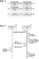
- FIG. 4 is a functional block diagram of each function implemented by executing the log processing program 135 or the log processing program 145.
- the log processing program 145 when executed, respective functions of an interruption notification unit 191, a log update suspension unit 192, a storage controller 193, a restoration notification unit 194, a log transfer unit 195, and an output controller 196 are implemented.
- the master-side CPU selects and executes the master-side function among these functions, and the slave-side CPU selects and executes the slave-side function among these functions.
- FIG. 5 is a sequence diagram illustrating a system operation when communication interruption occurs.
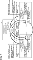
- FIG. 6 is a diagram schematically illustrating a system operation when communication interruption occurs. Note that, as an example, the CPU 134 of the first MFP 1 is set to the master-side CPU, and the CPU 144 of the second MFP 2 is set to the slave-side CPU.
- the master-side CPU 134 functions as the interruption notification unit 191 as an example of an abnormality notification unit to transmit the communication interruption notification signal (notification number) to the slave-side CPU 144 via the emergency signal line 180 as an example of a second signal line (step S1: interruption notification).
- the slave-side CPU 144 Upon receiving the communication interruption notification signal, the slave-side CPU 144 forms log information at the time of occurrence of the abnormality (communication interruption occurrence log information) and temporarily controls storage in the volatile memory 146 as an example of the second storage unit or a second memory.
- the CPU 144 functions as the log update suspension unit 192 to suspend a process of updating the log information until the communication abnormality record information is transferred to the nonvolatile memory 148 by the log transfer unit 195 as an example of a transfer unit described later or until communication of the normal signal line 154 is restored (step S2).
- the slave-side CPU 144 functions as the log transfer unit 195 to transfer the communication interruption occurrence log information from the volatile memory 146 to the nonvolatile memory 148 and save the communication interruption occurrence log information.
- the communication interruption occurrence log information stored in the volatile memory 146 is transferred to the nonvolatile memory 148 and saved.
- the log update suspension unit 192 may not suspend update of the log information, and the log transfer unit 195 may immediately transfer the communication interruption occurrence log information stored in the volatile memory 146 to the nonvolatile memory 148 and save the communication interruption occurrence log information.
- the log update suspension unit 192 may not be used, and program configurations of the log processing programs 135 and 145 may be simplified.
- the master-side CPU 134 functions as the restoration notification unit 194 and transmits restoration notification to the slave-side CPU 144 (step S4).
- the slave-side CPU 144 functions as the storage controller 193 to read the communication interruption occurrence log information saved in the nonvolatile memory 148.
- the slave-side CPU 144 functions as the output controller 196 as an example of the transmission unit to transfer the communication interruption occurrence log information read from the nonvolatile memory 148 to the master-side CPU 134 via the restored normal signal line 154 (step S5).
- the master-side CPU 134 functions as the storage controller 193 as an example of a communication abnormality storage controller to control storage of the communication interruption occurrence log information received from the slave-side CPU 144 in the nonvolatile memory 138 as an example of a communication abnormality storage unit on the master side (step S6). In this way, it is possible to acquire the communication interruption occurrence log information formed when communication interruption occurs, and it is possible to analyze investigation of a cause of the occurrence of the communication interruption.
- the communication interruption occurrence log information may be written when an abnormality occurs.
- the nonvolatile memory 138 can be used for a long time.
- the communication interruption occurrence log information protected on the slave side is stored in the nonvolatile memory 138 on the master side.
- the communication interruption occurrence log information stored in the nonvolatile memory 148 on the slave side may be output to a debugging device (an example of an external device for debugging) externally connected to the slave-side CPU 144.
- the slave-side CPU 144 functions as the output controller 196 (an example of an output unit) and outputs the communication interruption occurrence log information read from the nonvolatile memory 148 on the slave side to the debugging device (step S7).
- the debugging device can analyze the communication interruption occurrence log information to investigate a cause of the communication interruption.
- the image forming system of the embodiment can save the communication interruption occurrence log information formed when the communication interruption of the normal signal line 154 occurs without losing the communication interruption occurrence log information on the slave side. Then, when the normal signal line 154 is restored, the communication interruption occurrence log information protected on the slave side is transferred to the master side. In this way, it is possible to reliably acquire the communication interruption occurrence log information, which is formed when communication interruption occurs, on the master side, and it is possible to analyze investigation of a cause of the occurrence of the communication interruption.
- the communication interruption occurrence log information is formed when communication interruption occurs, which is an example. It should be understood that when any error occurs, error information indicating the occurring error is formed.
- a total of two MFPs that is, the first MFP 1 and the second MFP 2 are formed by interconnecting the normal signal line 154 and the emergency signal line 180. Three or more MFPs may be connected to each other.
- FIG. 7 illustrates an example in which first to third MFPs 1 to 3 are interconnected to by the normal signal line 154 and the emergency signal line 180.
- a first CPU 134 of the first MFP 1 is a main CPU, and controls the first MFP 1 and peripheral devices connected to the first MFP 1.
- a second CPU 144 of the second MFP 2 is a slave CPU, and controls the second MFP 2 and peripheral devices connected to the second MFP 2.
- a third CPU 174 of the third MFP 3 is a slave CPU, and controls the third MFP 3 and peripheral devices connected to the third MFP 3.
- the respective MFPs 1 to 3 are interconnected by the normal signal line 154 and the emergency signal line 180.
- the first to third CPUs 134, 144, and 174 of the respective MFPs 1 to 3 can operate as master CPUs. When any one CPU operates as a master CPU, the CPUs of the other MFPs operate as slave CPUs.
- the first CPU 134 serving as the master CPU stores log information indicating operation states of the first MFP 1 and the peripheral devices in the nonvolatile memory 138.
- the second CPU 144 serving as the slave CPU stores log information indicating operation states of the second MFP 2 and the peripheral devices in the volatile memory 146.
- the third CPU 174 serving as the slave CPU stores, in the volatile memory 178, log information indicating operation states of the third MFP 3 and the peripheral devices.
- a communication interruption notification signal is transmitted from the first CPU 134 to the third CPU 174 via the above-described emergency signal line 180.
- the third CPU 174 receiving the communication interruption notification signal suspends a process of updating the log information in the volatile memory 178. Then, the communication interruption occurrence log information formed when the communication interruption occurs is transferred from the volatile memory 178 to the nonvolatile memory 176 and protected.
- the third CPU 174 transmits the communication interruption occurrence log information protected by the nonvolatile memory 176 to the first CPU 134 via the normal signal line 154. In this way, the first CPU 134 can analyze the communication interruption log information when the communication interruption occurs.
- the debugging device may be connected to the third MFP 3 and the communication interruption occurrence log information stored in the nonvolatile memory 176 may be output to the debugging device. Further, even when three or more MFPs are connected in this way, the communication interruption log information at the time of occurrence of communication interruption may be saved and reliably referred to during analysis, etc.
- the above-described embodiments are examples of application to a system in which a plurality of image forming apparatuses such as MFPs is connected to each other.
- the present invention may be applied to any system in which devices can communicate with each other.
- the embodiments and variations of the respective embodiments are included in the scope and the gist of the present invention, and are included in the invention described in the claims and the equivalents thereof.
- elements and/or features of different illustrative embodiments may be combined with each other and/or substituted for each other within the scope of the present invention.
- the present invention can be implemented in any convenient form, for example using dedicated hardware, or a mixture of dedicated hardware and software.
- the present invention may be implemented as computer software implemented by one or more networked processing apparatuses.
- the processing apparatuses include any suitably programmed apparatuses such as a general purpose computer, personal digital assistant, mobile telephone (such as a WAP or 3G-compliant phone) and so on. Since the present invention can be implemented as software, each and every aspect of the present invention thus encompasses computer software implementable on a programmable device.
- the computer software can be provided to the programmable device using any conventional carrier medium (carrier means).
- the carrier medium includes a transient carrier medium such as an electrical, optical, microwave, acoustic or radio frequency signal carrying the computer code.
- transient medium is a TCP/IP signal carrying computer code over an IP network, such as the Internet.
- the carrier medium may also include a storage medium for storing processor readable code such as a floppy disk, hard disk, CD ROM, magnetic tape device or solid state memory device.
Landscapes
- Engineering & Computer Science (AREA)
- Biomedical Technology (AREA)
- Health & Medical Sciences (AREA)
- General Health & Medical Sciences (AREA)
- Theoretical Computer Science (AREA)
- Multimedia (AREA)
- Signal Processing (AREA)
- Quality & Reliability (AREA)
- General Engineering & Computer Science (AREA)
- General Physics & Mathematics (AREA)
- Physics & Mathematics (AREA)
- Facsimiles In General (AREA)
- Accessory Devices And Overall Control Thereof (AREA)
- Small-Scale Networks (AREA)
Abstract
Description
- Aspects of the present disclosure relate to an information processing device, an image forming apparatus, an image forming system, and an information processing method.
- At present, there is known an electronic device that stores log information at the time of occurrence of an abnormality in order to analyze a cause when the abnormality occurs.
- In addition,
JP-2005-311640-A - In this machine scheduled suspension checking system capable of performing detection, a machine operation checking processor checks the operation of the monitored machine, and a scheduled suspension flag file transfer processor transfers scheduled suspension information of the monitored machine to the monitoring machine and stores the information in a scheduled suspension flag file storage area. A machine operation checking table update processor reflects the scheduled suspension information stored in the scheduled suspension flag file storage area in a database of a machine operation checking table.
- Furthermore, there is also known an electronic device that stores log information in a large-capacity memory of a master-side central processing unit (CPU) (management-side) while filing the log information, and refers back to the log information when an abnormality occurs in the case where mutual communication is disconnected, thereby being able to detect a state at the time of occurrence of the abnormality.
- However, in an electronic device including two or more CPUs, when mutual communication between the master-side CPU (management-side) and a slave-side CPU is interrupted, it becomes difficult to save log information in real time as to a cause of the slave-side CPU becoming abnormal. As a result, there is a disadvantage that it becomes difficult to analyze the cause of the occurrence of the abnormality.
- The present invention has been made in view of the above-described problem, and an object of the present invention is to provide an information processing device, an image forming apparatus, an image forming system, and an information processing method capable of saving record information of an abnormality occurring during mutual communication of a plurality of devices without losing the record information.
- In an aspect of the present disclosure, there is provided an information processing device that includes control circuitry. The control circuitry is configured to store, in a first memory, record information formed each time a predetermined event occurs in a device and perform an update process of successively updating an old piece of record information with a new piece of record information in the record information stored in the first memory; transmit the record information stored in the first memory via a first signal line; transfer communication abnormality record information corresponding to the record information stored in the first memory to a second memory, which is configured not to update record information, and store the communication abnormality record information in the second memory when a communication abnormality signal indicating a communication abnormality of the first signal line is supplied via a second signal line; and transmit the communication abnormality record information stored in the second memory via the first signal line when communication of the first signal line is restored.
- In another aspect of the present disclosure, there is provided an image forming apparatus that includes the information processing device and an image forming device configured to form a predetermined image.
- In still another aspect of the present disclosure, there is provided an image forming system that includes a first image forming apparatus, a second image forming apparatus, the first signal line, and the second signal line. The first image forming apparatus is configured to form an image. The second image forming apparatus is the above-described image forming apparatus configured to form an image. The first signal line connects the first image forming apparatus and the second image forming apparatus for communication. The second signal line connects the first image forming apparatus and the second image forming apparatus for communication. The first image forming apparatus includes control circuitry configured to transmit the communication abnormality signal indicating the communication abnormality of the first signal line to the second image forming apparatus via the second signal line when the communication abnormality of the first signal line is detected; and acquire the communication abnormality record information corresponding to the communication abnormality of the first signal line transmitted from the second image forming apparatus via the first signal line and store the acquired communication abnormality record information in a communication abnormality memory when communication of the first signal line is restored. The control circuitry of the second image forming apparatus is configured to transmit the communication abnormality record information stored in the second memory to the first image forming apparatus via the first signal line when communication of the first signal line is restored.
- In still yet another aspect of the present disclosure, there is provided an information processing method comprising: storing, in a first memory, record information formed each time a predetermined event occurs in a device; performing an update process of successively updating an old piece of record information with a new piece of record information in the record information stored in the first memory; transmitting the record information stored in the first memory via a first signal line; transferring communication abnormality record information corresponding to the record information stored in the first memory to a second memory, which is configured not to update record information and causing the second memory to store the communication abnormality record information when a communication abnormality signal indicating a communication abnormality of the first signal line is supplied via a second signal line; and transmitting the communication abnormality record information stored in the second memory via the first signal line when communication of the first signal line is restored.
- According to the present invention, an effect can be obtained that it is possible to save record information of an abnormality occurring in mutual communications of a plurality of devices without losing the record information.
- A more complete appreciation of the disclosure and many of the attendant advantages and features thereof can be readily obtained and understood from the following detailed description with reference to the accompanying drawings, wherein:
-
FIG. 1 is a system configuration diagram of an image forming system of an embodiment; -
FIG. 2 is a block diagram for description of inconvenience when communication of each multifunction peripheral (MFP) is interrupted; -
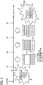
FIG. 3 is a schematic view for description of inconvenience when communication of each MFP is interrupted; -
FIG. 4 is a functional block diagram of each function implemented by executing a log processing program; -
FIG. 5 is a sequence diagram illustrating a system operation of an image forming system of a first embodiment when communication interruption occurs; -
FIG. 6 is a diagram schematically illustrating a system operation of the image forming system of the first embodiment when communication interruption occurs; and -
FIG. 7 is a system configuration diagram of an image forming system corresponding to a modification. - The accompanying drawings are intended to depict embodiments of the present disclosure and should not be interpreted to limit the scope thereof. The accompanying drawings are not to be considered as drawn to scale unless explicitly noted.
- The terminology used herein is for the purpose of describing particular embodiments only and is not intended to be limiting of the present disclosure. As used herein, the singular forms "a", "an" and "the" are intended to include the plural forms as well, unless the context clearly indicates otherwise.
- In describing embodiments illustrated in the drawings, specific terminology is employed for the sake of clarity. However, the disclosure of this specification is not intended to be limited to the specific terminology so selected and it is to be understood that each specific element includes all technical equivalents that have a similar function, operate in a similar manner, and achieve a similar result.
- Hereinafter, an image forming system of an embodiment will be described with reference to the accompanying drawings.
-
FIG. 1 is a system configuration diagram of an image forming system of an embodiment. As illustrated inFIG. 1 , the image forming system of the embodiment is formed by interconnecting a first MFP 1 and asecond MFP 2 through anormal signal line 154 and anemergency signal line 180. Referring to interconnected MFPs, three or more MFPs may be interconnected to form the image forming system. - For example, the
MFPs 1 and 2 includeimage forming devices 160 and 170 (examples of an image forming unit), respectively, having image forming functions such as a copy function, a scanner function, a printing function, and a facsimile transmission/reception function. Note that any one of the image forming functions may be provided, or a plurality of the image forming functions may be provided. - Further, in addition to the
image forming device 160 having such an image forming function(s), the first MFP 1 includes asystem controller 130, amemory unit 131, areading unit 132, awriting unit 133, and a customer support system (CSS) 137 that is a remote diagnosis system. - The
system controller 130 includes a central processing unit (CPU) 134. Thememory unit 131 has avolatile memory 136 and anonvolatile memory 138. Further, thememory unit 131 stores alog processing program 135. TheCPU 134 of thesystem controller 130 executes thelog processing program 135 to collect log information at the time of an emergency such as interruption of communication with thesecond MFP 2 from thesecond MFP 2 when communication is restored. As a result, it is possible to analyze a cause of the communication interruption, etc. Details will be described later. - Similarly to the first MFP 1, in addition to the image forming device 170 having the image forming function(s), the
second MFP 2 includes asystem controller 140, a memory unit 141, areading unit 142, awriting unit 143, and aCSS 150. - The
system controller 140 includes aCPU 144. The memory unit 141 includes a volatile memory 146 (an example of a first storage unit) and a nonvolatile memory 148 (an example of a second storage unit). Further, the memory unit 141 stores alog processing program 145. TheCPU 144 of thesystem controller 140 executes thelog processing program 145 to store log information at the time of interruption of communication with the first MFP 1, and transmits the log information to the first MFP 1 when communication is restored. As a result, it is possible to analyze a cause at the time of the communication interruption, etc. Details will be described later. - The first MFP 1 and the
second MFP 2 are interconnected by thenormal signal line 154 and theemergency signal line 180. The first MFP 1 and thesecond MFP 2 normally communicate with each other via thenormal signal line 154. When communication is interrupted, occurrence of communication interruption is notified from a master-side CPU to a slave-side CPU via the emergency signal line 180 (communication interruption notification signal). The slave-side CPU receiving the communication interruption notification signal (an example of a communication abnormality signal) saves and stores log information at the time of occurrence of the abnormality in the nonvolatile memory. Then, when communication is restored, the slave-side CPU reads the log information at the time of occurrence of communication interruption from the nonvolatile memory, and transmits the log information to a mater-side MFP via thenormal signal line 154. In this way, it is possible to analyze the log information at the time of occurrence of communication interruption. The log information is an example of record information. - Here, a description will be given of an inconvenience at the time of communication interruption of each of the
MFPs 1 and 2 based onFIG. 2 . For example, it is presumed that the first MFP 1 and thesecond MFP 2 are interconnected by the normal signal line 154 (an example of a first signal line), theCPU 134 of the first MFP 1 operates as a master CPU, and theCPU 144 of thesecond MFP 2 operates as a slave CPU. Themaster CPU 134 of the first MFP 1 controls the entire first MFP 1 and peripheral devices connected to the first MFP 1. Similarly, theCPU 144 of thesecond MFP 2 controls the entiresecond MFP 2 and peripheral devices connected to thesecond MFP 2. - The
CPU 134 of the first MFP 1 on the master side and theCPU 144 of thesecond MFP 2 on the slave side communicate with each other. The master-side CPU 134 stores, in thenonvolatile memory 138, log information indicating operation states of the own device and the peripheral device. The slave-side CPU 144 temporarily stores log information indicating operation states of the own device and the peripheral device in thevolatile memory 146, and transmits the log information to the first MFP 1 at a predetermined timing. Themaster CPU 134 of the first MFP 1 stores the log information acquired from thesecond MFP 2 in thenonvolatile memory 138. In this way, when an abnormality occurs, by analyzing the log information on the first MFP 1 side stored in thenonvolatile memory 138 of the first MFP 1 and the log information on thesecond MFP 2 side, it is possible to investigate a cause of the occurrence of the abnormality. - Here, as illustrated in
FIG. 3 , it is presumed that immediately after the master-side CPU 134 starts communication with the slave-side CPU 144 (immediately after starting), communication between therespective CPUs side CPU 144 and temporarily stored in thevolatile memory 146. - The temporarily stored communication interruption occurrence log information is transmitted from the
second MFP 2 on the slave side to the first MFP 1, and is stored in thenonvolatile memory 138 of the first MFP 1. However, when communication interruption between therespective CPUs second MFP 2 to the first MFP 1, and the communication interruption occurrence log information is temporarily stored in thevolatile memory 146 of thesecond MFP 2. In this state, when subsequent log information (second log, third log ...) is formed, the subsequent log information is overwritten on the communication interruption occurrence log information, and the inconvenience of losing the communication interruption occurrence log information occurs. - For this reason, the image forming system of the embodiment connects the master-side MFP and the slave-side MFP with each other via the
normal signal line 154, and connects the master-side MFP and the slave-side MFP with each other via the emergency signal line 180 (an example of a second signal line). Then, when communication interruption of thenormal signal line 154 occurs, a communication interruption notification signal is transmitted from the master-side MFP to the slave-side MFP via theemergency signal line 180. Upon receiving the communication interruption notification signal, the slave-side MFP saves and stores log information at the time of occurrence of the abnormality in the nonvolatile memory. Then, when thenormal signal line 154 is restored, the slave-side MFP reads the log information at the time of occurrence of communication interruption from the nonvolatile memory, and transmits the log information to the mater-side MFP via thenormal signal line 154. In this way, it is possible to analyze the log information at the time of occurrence of communication interruption. - Such operation at the time of occurrence of communication interruption is implemented by the
respective CPUs log processing program 135 or thelog processing program 145 illustrated inFIG. 1 . Thelog processing program 135 or thelog processing program 145 is a program having the same function, and the CPU operating as the master side implements the function on the master side based on the log processing program. Further, the CPU operating as the slave side implements the function on the slave side based on the log processing program. - That is,
FIG. 4 is a functional block diagram of each function implemented by executing thelog processing program 135 or thelog processing program 145. As illustrated inFIG. 4 , when thelog processing program 145 is executed, respective functions of aninterruption notification unit 191, a logupdate suspension unit 192, astorage controller 193, arestoration notification unit 194, alog transfer unit 195, and anoutput controller 196 are implemented. The master-side CPU selects and executes the master-side function among these functions, and the slave-side CPU selects and executes the slave-side function among these functions. -
FIG. 5 is a sequence diagram illustrating a system operation when communication interruption occurs. In addition,FIG. 6 is a diagram schematically illustrating a system operation when communication interruption occurs. Note that, as an example, theCPU 134 of the first MFP 1 is set to the master-side CPU, and theCPU 144 of thesecond MFP 2 is set to the slave-side CPU. - While communication is normally performed between the first MFP 1 and the
second MFP 2, the log information generated by thesecond MFP 2 is read from thevolatile memory 146 as an example of the first storage unit or a first memory by thestorage controller 193 as an example of a storage controller, transmitted to the first MFP 1 via thenormal signal line 154 as an example of a first signal line by theoutput controller 196 as an example of a transmission unit, and stored in thenonvolatile memory 138. - However, as illustrated in
FIG. 5 andFIG. 6 , when communication interruption of thenormal signal line 154 occurs, the master-side CPU 134 functions as theinterruption notification unit 191 as an example of an abnormality notification unit to transmit the communication interruption notification signal (notification number) to the slave-side CPU 144 via theemergency signal line 180 as an example of a second signal line (step S1: interruption notification). - Upon receiving the communication interruption notification signal, the slave-
side CPU 144 forms log information at the time of occurrence of the abnormality (communication interruption occurrence log information) and temporarily controls storage in thevolatile memory 146 as an example of the second storage unit or a second memory. In addition, theCPU 144 functions as the logupdate suspension unit 192 to suspend a process of updating the log information until the communication abnormality record information is transferred to thenonvolatile memory 148 by thelog transfer unit 195 as an example of a transfer unit described later or until communication of thenormal signal line 154 is restored (step S2). Then, the slave-side CPU 144 functions as thelog transfer unit 195 to transfer the communication interruption occurrence log information from thevolatile memory 146 to thenonvolatile memory 148 and save the communication interruption occurrence log information. As a result, erroneous erasure due to updating of the log information and erroneous erasure due to non-energization of thenonvolatile memory 148 are prevented, so that it is possible to protect the communication interruption occurrence log information. - In this example, when an abnormality occurs, after the process of updating the
volatile memory 146 is suspended, the communication interruption occurrence log information stored in thevolatile memory 146 is transferred to thenonvolatile memory 148 and saved. However, when the communication interruption notification signal is supplied via theemergency signal line 180, the logupdate suspension unit 192 may not suspend update of the log information, and thelog transfer unit 195 may immediately transfer the communication interruption occurrence log information stored in thevolatile memory 146 to thenonvolatile memory 148 and save the communication interruption occurrence log information. In this case, the logupdate suspension unit 192 may not be used, and program configurations of thelog processing programs - Subsequently, when communication with the slave-
side CPU 144 via thenormal signal line 154 is restored, the master-side CPU 134 functions as therestoration notification unit 194 and transmits restoration notification to the slave-side CPU 144 (step S4). Upon receiving the restoration notification, the slave-side CPU 144 functions as thestorage controller 193 to read the communication interruption occurrence log information saved in thenonvolatile memory 148. In addition, the slave-side CPU 144 functions as theoutput controller 196 as an example of the transmission unit to transfer the communication interruption occurrence log information read from thenonvolatile memory 148 to the master-side CPU 134 via the restored normal signal line 154 (step S5). - The master-
side CPU 134 functions as thestorage controller 193 as an example of a communication abnormality storage controller to control storage of the communication interruption occurrence log information received from the slave-side CPU 144 in thenonvolatile memory 138 as an example of a communication abnormality storage unit on the master side (step S6). In this way, it is possible to acquire the communication interruption occurrence log information formed when communication interruption occurs, and it is possible to analyze investigation of a cause of the occurrence of the communication interruption. - In the case where there is a limit to the allowed number of times of writing in the
nonvolatile memory 138, the communication interruption occurrence log information may be written when an abnormality occurs. In this case, thenonvolatile memory 138 can be used for a long time. - Further, in this example, the communication interruption occurrence log information protected on the slave side is stored in the
nonvolatile memory 138 on the master side. However, the communication interruption occurrence log information stored in thenonvolatile memory 148 on the slave side may be output to a debugging device (an example of an external device for debugging) externally connected to the slave-side CPU 144. In this case, the slave-side CPU 144 functions as the output controller 196 (an example of an output unit) and outputs the communication interruption occurrence log information read from thenonvolatile memory 148 on the slave side to the debugging device (step S7). In this way, the debugging device can analyze the communication interruption occurrence log information to investigate a cause of the communication interruption. - As is clear from the above description, the image forming system of the embodiment can save the communication interruption occurrence log information formed when the communication interruption of the
normal signal line 154 occurs without losing the communication interruption occurrence log information on the slave side. Then, when thenormal signal line 154 is restored, the communication interruption occurrence log information protected on the slave side is transferred to the master side. In this way, it is possible to reliably acquire the communication interruption occurrence log information, which is formed when communication interruption occurs, on the master side, and it is possible to analyze investigation of a cause of the occurrence of the communication interruption. - The communication interruption occurrence log information is formed when communication interruption occurs, which is an example. It should be understood that when any error occurs, error information indicating the occurring error is formed.
- In the above embodiment, a total of two MFPs, that is, the first MFP 1 and the
second MFP 2 are formed by interconnecting thenormal signal line 154 and theemergency signal line 180. Three or more MFPs may be connected to each other.FIG. 7 illustrates an example in which first to third MFPs 1 to 3 are interconnected to by thenormal signal line 154 and theemergency signal line 180. InFIG. 7 , afirst CPU 134 of the first MFP 1 is a main CPU, and controls the first MFP 1 and peripheral devices connected to the first MFP 1. Asecond CPU 144 of thesecond MFP 2 is a slave CPU, and controls thesecond MFP 2 and peripheral devices connected to thesecond MFP 2. Athird CPU 174 of thethird MFP 3 is a slave CPU, and controls thethird MFP 3 and peripheral devices connected to thethird MFP 3. - The respective MFPs 1 to 3 are interconnected by the
normal signal line 154 and theemergency signal line 180. The first tothird CPUs - In this example, the
first CPU 134 serving as the master CPU stores log information indicating operation states of the first MFP 1 and the peripheral devices in thenonvolatile memory 138. Thesecond CPU 144 serving as the slave CPU stores log information indicating operation states of thesecond MFP 2 and the peripheral devices in thevolatile memory 146. Similarly, thethird CPU 174 serving as the slave CPU stores, in the volatile memory 178, log information indicating operation states of thethird MFP 3 and the peripheral devices. - When communication interruption occurs between the
first CPU 134 and thethird CPU 174, a communication interruption notification signal is transmitted from thefirst CPU 134 to thethird CPU 174 via the above-describedemergency signal line 180. Thethird CPU 174 receiving the communication interruption notification signal suspends a process of updating the log information in the volatile memory 178. Then, the communication interruption occurrence log information formed when the communication interruption occurs is transferred from the volatile memory 178 to thenonvolatile memory 176 and protected. - When the
normal signal line 154 is restored, thethird CPU 174 transmits the communication interruption occurrence log information protected by thenonvolatile memory 176 to thefirst CPU 134 via thenormal signal line 154. In this way, thefirst CPU 134 can analyze the communication interruption log information when the communication interruption occurs. - Note that, as described above, the debugging device may be connected to the
third MFP 3 and the communication interruption occurrence log information stored in thenonvolatile memory 176 may be output to the debugging device. Further, even when three or more MFPs are connected in this way, the communication interruption log information at the time of occurrence of communication interruption may be saved and reliably referred to during analysis, etc. - Finally, the above-described embodiments have been presented as examples and are not intended to limit the scope of the present invention. The above-described embodiments can be implemented in various other forms, and various omissions, replacements, and changes can be made without departing from the spirit of the present invention.
- For example, the above-described embodiments are examples of application to a system in which a plurality of image forming apparatuses such as MFPs is connected to each other. However, even when the image forming apparatus is not used, the present invention may be applied to any system in which devices can communicate with each other. In addition, the embodiments and variations of the respective embodiments are included in the scope and the gist of the present invention, and are included in the invention described in the claims and the equivalents thereof. For example, elements and/or features of different illustrative embodiments may be combined with each other and/or substituted for each other within the scope of the present invention.
- Any one of the above-described operations may be performed in various other ways, for example, in an order different from the one described above.
- The present invention can be implemented in any convenient form, for example using dedicated hardware, or a mixture of dedicated hardware and software. The present invention may be implemented as computer software implemented by one or more networked processing apparatuses. The processing apparatuses include any suitably programmed apparatuses such as a general purpose computer, personal digital assistant, mobile telephone (such as a WAP or 3G-compliant phone) and so on. Since the present invention can be implemented as software, each and every aspect of the present invention thus encompasses computer software implementable on a programmable device. The computer software can be provided to the programmable device using any conventional carrier medium (carrier means). The carrier medium includes a transient carrier medium such as an electrical, optical, microwave, acoustic or radio frequency signal carrying the computer code. An example of such a transient medium is a TCP/IP signal carrying computer code over an IP network, such as the Internet. The carrier medium may also include a storage medium for storing processor readable code such as a floppy disk, hard disk, CD ROM, magnetic tape device or solid state memory device.
Claims (7)
- An information processing device comprising:a storage controller (193) configured to store, in a first storage unit (146), record information formed each time a predetermined event occurs in a device and perform an update process of successively updating an old piece of record information with a new piece of record information in the record information stored in the first storage unit (146);a transmission unit (196) configured to transmit the record information stored in the first storage unit (146) via a first signal line (154); anda transfer unit (195) configured to transfer communication abnormality record information corresponding to the record information stored in the first storage unit to a second storage unit (148), which is configured not to update record information, and store the communication abnormality record information in the second storage unit (148) when a communication abnormality signal indicating a communication abnormality of the first signal line is supplied via a second signal line (180),the transmission unit (196) configured to transmit the communication abnormality record information stored in the second storage unit via the first signal line when communication of the first signal line is restored.
- The information processing device according to claim 1, further comprising an output unit (196) configured to output the communication abnormality record information stored in the second storage unit (148) to an external device for debugging.
- The information processing device according to claim 1 or 2, further comprising an update suspension unit (192) configured to suspend the update process in the first storage unit until the communication abnormality record information is transferred to the second storage unit or until communication of the first signal line is restored, when the communication abnormality signal is supplied via the second signal line (148).
- The information processing device according to any one of claims 1 to 3,
wherein the first storage unit (146) is a volatile storage unit, and the second storage unit is a nonvolatile storage unit. - An image forming apparatus (2) comprising:the information processing device according to any one of claims 1 to 4; andan image forming device (170) configured to form a predetermined image.
- An image forming system comprising:a first image forming apparatus (1) configured to form an image; anda second image forming apparatus (2) that is the image forming apparatus (2) according to claim 5, configured to form an image;the first signal line (146) connecting the first image forming apparatus and the second image forming apparatus for communication; andthe second signal line (180) connecting the first image forming apparatus and the second image forming apparatus for communication,wherein the first image forming apparatus (1) includes:an abnormality notification unit (191) configured to transmit the communication abnormality signal indicating the communication abnormality of the first signal line to the second image forming apparatus via the second signal line when the communication abnormality of the first signal line is detected; anda communication abnormality storage controller (193) configured to acquire the communication abnormality record information corresponding to the communication abnormality of the first signal line transmitted from the second image forming apparatus via the first signal line and store the acquired communication abnormality record information in a communication abnormality storage unit (138) when communication of the first signal line is restored, andwherein the transmission unit of the second image forming apparatus is configured to transmit the communication abnormality record information stored in the second storage unit to the first image forming apparatus via the first signal line when communication of the first signal line is restored.
- An information processing method comprising:storing, in a first storage unit, record information formed each time a predetermined event occurs in a device;performing an update process of successively updating an old piece of record information with a new piece of record information in the record information stored in the first storage unit;transmitting the record information stored in the first storage unit via a first signal line;transferring communication abnormality record information corresponding to the record information stored in the first storage unit to a second storage unit, which is configured not to update record information and causing the second storage unit to store the communication abnormality record information when a communication abnormality signal indicating a communication abnormality of the first signal line is supplied via a second signal line; andtransmitting the communication abnormality record information stored in the second storage unit via the first signal line when communication of the first signal line is restored.
Applications Claiming Priority (1)
| Application Number | Priority Date | Filing Date | Title |
|---|---|---|---|
| JP2019022737A JP7251188B2 (en) | 2019-02-12 | 2019-02-12 | Information processing apparatus, image forming apparatus, image forming system, and information processing method |
Publications (2)
| Publication Number | Publication Date |
|---|---|
| EP3696675A1 true EP3696675A1 (en) | 2020-08-19 |
| EP3696675B1 EP3696675B1 (en) | 2021-09-08 |
Family
ID=69528683
Family Applications (1)
| Application Number | Title | Priority Date | Filing Date |
|---|---|---|---|
| EP20156299.8A Not-in-force EP3696675B1 (en) | 2019-02-12 | 2020-02-10 | Information processing device, image forming apparatus, image forming system, and information processing method |
Country Status (4)
| Country | Link |
|---|---|
| US (1) | US10992823B2 (en) |
| EP (1) | EP3696675B1 (en) |
| JP (1) | JP7251188B2 (en) |
| CN (1) | CN111556214B (en) |
Families Citing this family (1)
| Publication number | Priority date | Publication date | Assignee | Title |
|---|---|---|---|---|
| JP7803045B2 (en) * | 2021-05-18 | 2026-01-21 | 日本電気株式会社 | Support system, method, and program |
Citations (4)
| Publication number | Priority date | Publication date | Assignee | Title |
|---|---|---|---|---|
| JP2005311640A (en) | 2004-04-21 | 2005-11-04 | Hitachi Ltd | Machine planned stop confirmation system |
| US20080174819A1 (en) * | 2007-01-22 | 2008-07-24 | Canon Kabushiki Kaisha | Image forming apparatus and control method thereof |
| JP2014149676A (en) * | 2013-02-01 | 2014-08-21 | Ricoh Co Ltd | Image forming device and log management system |
| JP2018014039A (en) * | 2016-07-22 | 2018-01-25 | 株式会社リコー | Information processing device, information processing system, information processing method, and program |
Family Cites Families (15)
| Publication number | Priority date | Publication date | Assignee | Title |
|---|---|---|---|---|
| JP2000112706A (en) * | 1998-09-30 | 2000-04-21 | Canon Inc | Print log total management system, print log total management method, and storage medium |
| JP3656804B2 (en) | 1998-12-21 | 2005-06-08 | 株式会社リコー | Image forming system |
| JP2001022436A (en) * | 1999-07-07 | 2001-01-26 | Toshiba Corp | Process monitoring control device |
| JP3804770B2 (en) | 2001-11-12 | 2006-08-02 | オムロン株式会社 | Control system and slave |
| US7802145B1 (en) * | 2004-05-18 | 2010-09-21 | Cisco Technology, Inc. | Approach for facilitating analysis of computer software errors |
| JP4493461B2 (en) * | 2004-10-12 | 2010-06-30 | ティーオーエー株式会社 | Backup device, backup method and broadcasting system |
| JP2009083449A (en) * | 2007-10-03 | 2009-04-23 | Konica Minolta Business Technologies Inc | Image forming system |
| JP2009159519A (en) * | 2007-12-27 | 2009-07-16 | Ricoh Co Ltd | Image forming apparatus, program, and recording medium |
| JP5609436B2 (en) | 2010-08-30 | 2014-10-22 | セイコーエプソン株式会社 | Data storage processing apparatus, printing apparatus and data storage processing method in printing apparatus |
| JP2013131893A (en) | 2011-12-21 | 2013-07-04 | Sumitomo Electric Ind Ltd | Optical communication module, log recording method for optical communication module, and optical communication device |
| JP6258824B2 (en) * | 2014-09-16 | 2018-01-10 | 京セラ株式会社 | Communication device and communication device log storage method |
| JP6846111B2 (en) * | 2016-02-26 | 2021-03-24 | オムロン株式会社 | Master device, slave device, information processing device, event log collection system, master device control method, slave device control method, and control program |
| JP2019115185A (en) | 2017-12-25 | 2019-07-11 | 株式会社リコー | Power supply device and image forming apparatus |
| JP2019120582A (en) | 2018-01-05 | 2019-07-22 | 株式会社リコー | Characteristic detection device, media supply device, and image forming device |
| JP2019142095A (en) * | 2018-02-20 | 2019-08-29 | 京セラドキュメントソリューションズ株式会社 | Image formation apparatus |
-
2019
- 2019-02-12 JP JP2019022737A patent/JP7251188B2/en active Active
-
2020
- 2020-02-10 EP EP20156299.8A patent/EP3696675B1/en not_active Not-in-force
- 2020-02-11 CN CN202010087262.1A patent/CN111556214B/en active Active
- 2020-02-11 US US16/787,108 patent/US10992823B2/en active Active
Patent Citations (4)
| Publication number | Priority date | Publication date | Assignee | Title |
|---|---|---|---|---|
| JP2005311640A (en) | 2004-04-21 | 2005-11-04 | Hitachi Ltd | Machine planned stop confirmation system |
| US20080174819A1 (en) * | 2007-01-22 | 2008-07-24 | Canon Kabushiki Kaisha | Image forming apparatus and control method thereof |
| JP2014149676A (en) * | 2013-02-01 | 2014-08-21 | Ricoh Co Ltd | Image forming device and log management system |
| JP2018014039A (en) * | 2016-07-22 | 2018-01-25 | 株式会社リコー | Information processing device, information processing system, information processing method, and program |
Also Published As
| Publication number | Publication date |
|---|---|
| CN111556214B (en) | 2022-07-12 |
| EP3696675B1 (en) | 2021-09-08 |
| US20200259963A1 (en) | 2020-08-13 |
| JP2020129786A (en) | 2020-08-27 |
| US10992823B2 (en) | 2021-04-27 |
| JP7251188B2 (en) | 2023-04-04 |
| CN111556214A (en) | 2020-08-18 |
Similar Documents
| Publication | Publication Date | Title |
|---|---|---|
| CN112486629B (en) | Micro-service state detection method, micro-service state detection device, electronic equipment and storage medium | |
| CN104202201B (en) | A kind of log processing method, device and terminal | |
| US20070282999A1 (en) | Technique for collecting information about computing devices | |
| CN107800663A (en) | The detection method and device of flow off-line files | |
| CN120335845A (en) | Firmware upgrade system and method | |
| EP3696675B1 (en) | Information processing device, image forming apparatus, image forming system, and information processing method | |
| US11489746B2 (en) | Detection device, detection method, and detection program | |
| JP5217961B2 (en) | Electronic device, memory device determination system, and control method thereof | |
| JP4928480B2 (en) | Job processing system and job management method | |
| CN113014640B (en) | Request processing method, request processing device, electronic equipment and storage medium | |
| CN107959595B (en) | Anomaly detection method, device and system | |
| JP2011159011A (en) | System and program for monitoring job | |
| CN116991546B (en) | Cross-platform storage heat migration method and device | |
| US20090228548A1 (en) | Client terminal, client server system, data acquisition method, and program | |
| JP4500085B2 (en) | Test support apparatus and test support method | |
| JP2024136875A (en) | Information processing system and program | |
| CN103530071B (en) | Print control unit and image formation system | |
| WO2023112359A1 (en) | Communication system, management apparatus, and terminal | |
| US9336181B2 (en) | Retrieval of measured values, diagnostic information or device parameters | |
| JP2010066798A (en) | Image processing apparatus, and user authentication method of image processing apparatus | |
| JP2005322024A (en) | Anomaly information output device, anomaly detection system, and anomaly information output method | |
| US20240184643A1 (en) | Proactive monitoring of file status updates in transaction systems | |
| CN110661672B (en) | Network information processing method for android device and android device | |
| CN115033418A (en) | Log storage method, device and equipment | |
| JP2006268612A (en) | Processing time measuring system and processing time measuring program |
Legal Events
| Date | Code | Title | Description |
|---|---|---|---|
| PUAI | Public reference made under article 153(3) epc to a published international application that has entered the european phase |
Free format text: ORIGINAL CODE: 0009012 |
|
| STAA | Information on the status of an ep patent application or granted ep patent |
Free format text: STATUS: REQUEST FOR EXAMINATION WAS MADE |
|
| 17P | Request for examination filed |
Effective date: 20200210 |
|
| AK | Designated contracting states |
Kind code of ref document: A1 Designated state(s): AL AT BE BG CH CY CZ DE DK EE ES FI FR GB GR HR HU IE IS IT LI LT LU LV MC MK MT NL NO PL PT RO RS SE SI SK SM TR |
|
| AX | Request for extension of the european patent |
Extension state: BA ME |
|
| GRAP | Despatch of communication of intention to grant a patent |
Free format text: ORIGINAL CODE: EPIDOSNIGR1 |
|
| STAA | Information on the status of an ep patent application or granted ep patent |
Free format text: STATUS: GRANT OF PATENT IS INTENDED |
|
| INTG | Intention to grant announced |
Effective date: 20210409 |
|
| GRAS | Grant fee paid |
Free format text: ORIGINAL CODE: EPIDOSNIGR3 |
|
| GRAA | (expected) grant |
Free format text: ORIGINAL CODE: 0009210 |
|
| STAA | Information on the status of an ep patent application or granted ep patent |
Free format text: STATUS: THE PATENT HAS BEEN GRANTED |
|
| AK | Designated contracting states |
Kind code of ref document: B1 Designated state(s): AL AT BE BG CH CY CZ DE DK EE ES FI FR GB GR HR HU IE IS IT LI LT LU LV MC MK MT NL NO PL PT RO RS SE SI SK SM TR |
|
| REG | Reference to a national code |
Ref country code: GB Ref legal event code: FG4D |
|
| REG | Reference to a national code |
Ref country code: CH Ref legal event code: EP Ref country code: AT Ref legal event code: REF Ref document number: 1429204 Country of ref document: AT Kind code of ref document: T Effective date: 20210915 |
|
| REG | Reference to a national code |
Ref country code: IE Ref legal event code: FG4D |
|
| REG | Reference to a national code |
Ref country code: DE Ref legal event code: R096 Ref document number: 602020000489 Country of ref document: DE |
|
| REG | Reference to a national code |
Ref country code: NL Ref legal event code: FP |
|
| REG | Reference to a national code |
Ref country code: LT Ref legal event code: MG9D |
|
| PG25 | Lapsed in a contracting state [announced via postgrant information from national office to epo] |
Ref country code: LT Free format text: LAPSE BECAUSE OF FAILURE TO SUBMIT A TRANSLATION OF THE DESCRIPTION OR TO PAY THE FEE WITHIN THE PRESCRIBED TIME-LIMIT Effective date: 20210908 Ref country code: BG Free format text: LAPSE BECAUSE OF FAILURE TO SUBMIT A TRANSLATION OF THE DESCRIPTION OR TO PAY THE FEE WITHIN THE PRESCRIBED TIME-LIMIT Effective date: 20211208 Ref country code: HR Free format text: LAPSE BECAUSE OF FAILURE TO SUBMIT A TRANSLATION OF THE DESCRIPTION OR TO PAY THE FEE WITHIN THE PRESCRIBED TIME-LIMIT Effective date: 20210908 Ref country code: FI Free format text: LAPSE BECAUSE OF FAILURE TO SUBMIT A TRANSLATION OF THE DESCRIPTION OR TO PAY THE FEE WITHIN THE PRESCRIBED TIME-LIMIT Effective date: 20210908 Ref country code: NO Free format text: LAPSE BECAUSE OF FAILURE TO SUBMIT A TRANSLATION OF THE DESCRIPTION OR TO PAY THE FEE WITHIN THE PRESCRIBED TIME-LIMIT Effective date: 20211208 Ref country code: RS Free format text: LAPSE BECAUSE OF FAILURE TO SUBMIT A TRANSLATION OF THE DESCRIPTION OR TO PAY THE FEE WITHIN THE PRESCRIBED TIME-LIMIT Effective date: 20210908 Ref country code: SE Free format text: LAPSE BECAUSE OF FAILURE TO SUBMIT A TRANSLATION OF THE DESCRIPTION OR TO PAY THE FEE WITHIN THE PRESCRIBED TIME-LIMIT Effective date: 20210908 Ref country code: ES Free format text: LAPSE BECAUSE OF FAILURE TO SUBMIT A TRANSLATION OF THE DESCRIPTION OR TO PAY THE FEE WITHIN THE PRESCRIBED TIME-LIMIT Effective date: 20210908 |
|
| REG | Reference to a national code |
Ref country code: AT Ref legal event code: MK05 Ref document number: 1429204 Country of ref document: AT Kind code of ref document: T Effective date: 20210908 |
|
| PG25 | Lapsed in a contracting state [announced via postgrant information from national office to epo] |
Ref country code: LV Free format text: LAPSE BECAUSE OF FAILURE TO SUBMIT A TRANSLATION OF THE DESCRIPTION OR TO PAY THE FEE WITHIN THE PRESCRIBED TIME-LIMIT Effective date: 20210908 Ref country code: GR Free format text: LAPSE BECAUSE OF FAILURE TO SUBMIT A TRANSLATION OF THE DESCRIPTION OR TO PAY THE FEE WITHIN THE PRESCRIBED TIME-LIMIT Effective date: 20211209 |
|
| PG25 | Lapsed in a contracting state [announced via postgrant information from national office to epo] |
Ref country code: AT Free format text: LAPSE BECAUSE OF FAILURE TO SUBMIT A TRANSLATION OF THE DESCRIPTION OR TO PAY THE FEE WITHIN THE PRESCRIBED TIME-LIMIT Effective date: 20210908 |
|
| PGFP | Annual fee paid to national office [announced via postgrant information from national office to epo] |
Ref country code: DE Payment date: 20220217 Year of fee payment: 3 |
|
| PG25 | Lapsed in a contracting state [announced via postgrant information from national office to epo] |
Ref country code: IS Free format text: LAPSE BECAUSE OF FAILURE TO SUBMIT A TRANSLATION OF THE DESCRIPTION OR TO PAY THE FEE WITHIN THE PRESCRIBED TIME-LIMIT Effective date: 20220108 Ref country code: SM Free format text: LAPSE BECAUSE OF FAILURE TO SUBMIT A TRANSLATION OF THE DESCRIPTION OR TO PAY THE FEE WITHIN THE PRESCRIBED TIME-LIMIT Effective date: 20210908 Ref country code: SK Free format text: LAPSE BECAUSE OF FAILURE TO SUBMIT A TRANSLATION OF THE DESCRIPTION OR TO PAY THE FEE WITHIN THE PRESCRIBED TIME-LIMIT Effective date: 20210908 Ref country code: RO Free format text: LAPSE BECAUSE OF FAILURE TO SUBMIT A TRANSLATION OF THE DESCRIPTION OR TO PAY THE FEE WITHIN THE PRESCRIBED TIME-LIMIT Effective date: 20210908 Ref country code: PT Free format text: LAPSE BECAUSE OF FAILURE TO SUBMIT A TRANSLATION OF THE DESCRIPTION OR TO PAY THE FEE WITHIN THE PRESCRIBED TIME-LIMIT Effective date: 20220110 Ref country code: PL Free format text: LAPSE BECAUSE OF FAILURE TO SUBMIT A TRANSLATION OF THE DESCRIPTION OR TO PAY THE FEE WITHIN THE PRESCRIBED TIME-LIMIT Effective date: 20210908 Ref country code: EE Free format text: LAPSE BECAUSE OF FAILURE TO SUBMIT A TRANSLATION OF THE DESCRIPTION OR TO PAY THE FEE WITHIN THE PRESCRIBED TIME-LIMIT Effective date: 20210908 Ref country code: CZ Free format text: LAPSE BECAUSE OF FAILURE TO SUBMIT A TRANSLATION OF THE DESCRIPTION OR TO PAY THE FEE WITHIN THE PRESCRIBED TIME-LIMIT Effective date: 20210908 Ref country code: AL Free format text: LAPSE BECAUSE OF FAILURE TO SUBMIT A TRANSLATION OF THE DESCRIPTION OR TO PAY THE FEE WITHIN THE PRESCRIBED TIME-LIMIT Effective date: 20210908 |
|
| PGFP | Annual fee paid to national office [announced via postgrant information from national office to epo] |
Ref country code: FR Payment date: 20220216 Year of fee payment: 3 |
|
| REG | Reference to a national code |
Ref country code: DE Ref legal event code: R097 Ref document number: 602020000489 Country of ref document: DE |
|
| PLBE | No opposition filed within time limit |
Free format text: ORIGINAL CODE: 0009261 |
|
| STAA | Information on the status of an ep patent application or granted ep patent |
Free format text: STATUS: NO OPPOSITION FILED WITHIN TIME LIMIT |
|
| PG25 | Lapsed in a contracting state [announced via postgrant information from national office to epo] |
Ref country code: DK Free format text: LAPSE BECAUSE OF FAILURE TO SUBMIT A TRANSLATION OF THE DESCRIPTION OR TO PAY THE FEE WITHIN THE PRESCRIBED TIME-LIMIT Effective date: 20210908 |
|
| 26N | No opposition filed |
Effective date: 20220609 |
|
| PG25 | Lapsed in a contracting state [announced via postgrant information from national office to epo] |
Ref country code: SI Free format text: LAPSE BECAUSE OF FAILURE TO SUBMIT A TRANSLATION OF THE DESCRIPTION OR TO PAY THE FEE WITHIN THE PRESCRIBED TIME-LIMIT Effective date: 20210908 |
|
| PG25 | Lapsed in a contracting state [announced via postgrant information from national office to epo] |
Ref country code: MC Free format text: LAPSE BECAUSE OF FAILURE TO SUBMIT A TRANSLATION OF THE DESCRIPTION OR TO PAY THE FEE WITHIN THE PRESCRIBED TIME-LIMIT Effective date: 20210908 |
|
| REG | Reference to a national code |
Ref country code: BE Ref legal event code: MM Effective date: 20220228 |
|
| PG25 | Lapsed in a contracting state [announced via postgrant information from national office to epo] |
Ref country code: LU Free format text: LAPSE BECAUSE OF NON-PAYMENT OF DUE FEES Effective date: 20220210 |
|
| PG25 | Lapsed in a contracting state [announced via postgrant information from national office to epo] |
Ref country code: IT Free format text: LAPSE BECAUSE OF FAILURE TO SUBMIT A TRANSLATION OF THE DESCRIPTION OR TO PAY THE FEE WITHIN THE PRESCRIBED TIME-LIMIT Effective date: 20210908 Ref country code: IE Free format text: LAPSE BECAUSE OF NON-PAYMENT OF DUE FEES Effective date: 20220210 |
|
| PG25 | Lapsed in a contracting state [announced via postgrant information from national office to epo] |
Ref country code: BE Free format text: LAPSE BECAUSE OF NON-PAYMENT OF DUE FEES Effective date: 20220228 |
|
| REG | Reference to a national code |
Ref country code: DE Ref legal event code: R119 Ref document number: 602020000489 Country of ref document: DE |
|
| REG | Reference to a national code |
Ref country code: CH Ref legal event code: PL |
|
| REG | Reference to a national code |
Ref country code: NL Ref legal event code: MM Effective date: 20230301 |
|
| PG25 | Lapsed in a contracting state [announced via postgrant information from national office to epo] |
Ref country code: LI Free format text: LAPSE BECAUSE OF NON-PAYMENT OF DUE FEES Effective date: 20230228 Ref country code: CH Free format text: LAPSE BECAUSE OF NON-PAYMENT OF DUE FEES Effective date: 20230228 |
|
| PG25 | Lapsed in a contracting state [announced via postgrant information from national office to epo] |
Ref country code: NL Free format text: LAPSE BECAUSE OF NON-PAYMENT OF DUE FEES Effective date: 20230301 |
|
| PG25 | Lapsed in a contracting state [announced via postgrant information from national office to epo] |
Ref country code: FR Free format text: LAPSE BECAUSE OF NON-PAYMENT OF DUE FEES Effective date: 20230228 Ref country code: DE Free format text: LAPSE BECAUSE OF NON-PAYMENT OF DUE FEES Effective date: 20230901 |
|
| PG25 | Lapsed in a contracting state [announced via postgrant information from national office to epo] |
Ref country code: MK Free format text: LAPSE BECAUSE OF FAILURE TO SUBMIT A TRANSLATION OF THE DESCRIPTION OR TO PAY THE FEE WITHIN THE PRESCRIBED TIME-LIMIT Effective date: 20210908 Ref country code: CY Free format text: LAPSE BECAUSE OF FAILURE TO SUBMIT A TRANSLATION OF THE DESCRIPTION OR TO PAY THE FEE WITHIN THE PRESCRIBED TIME-LIMIT Effective date: 20210908 |
|
| PG25 | Lapsed in a contracting state [announced via postgrant information from national office to epo] |
Ref country code: HU Free format text: LAPSE BECAUSE OF FAILURE TO SUBMIT A TRANSLATION OF THE DESCRIPTION OR TO PAY THE FEE WITHIN THE PRESCRIBED TIME-LIMIT; INVALID AB INITIO Effective date: 20200210 |
|
| PG25 | Lapsed in a contracting state [announced via postgrant information from national office to epo] |
Ref country code: MT Free format text: LAPSE BECAUSE OF FAILURE TO SUBMIT A TRANSLATION OF THE DESCRIPTION OR TO PAY THE FEE WITHIN THE PRESCRIBED TIME-LIMIT Effective date: 20210908 |
|
| GBPC | Gb: european patent ceased through non-payment of renewal fee |
Effective date: 20240210 |
|
| PG25 | Lapsed in a contracting state [announced via postgrant information from national office to epo] |
Ref country code: GB Free format text: LAPSE BECAUSE OF NON-PAYMENT OF DUE FEES Effective date: 20240210 |
|
| PG25 | Lapsed in a contracting state [announced via postgrant information from national office to epo] |
Ref country code: GB Free format text: LAPSE BECAUSE OF NON-PAYMENT OF DUE FEES Effective date: 20240210 |
|
| PG25 | Lapsed in a contracting state [announced via postgrant information from national office to epo] |
Ref country code: TR Free format text: LAPSE BECAUSE OF FAILURE TO SUBMIT A TRANSLATION OF THE DESCRIPTION OR TO PAY THE FEE WITHIN THE PRESCRIBED TIME-LIMIT Effective date: 20210908 |