EP3696530A1 - Cryogenic transmission electron microscopy sample preparation - Google Patents
Cryogenic transmission electron microscopy sample preparation Download PDFInfo
- Publication number
- EP3696530A1 EP3696530A1 EP20157128.8A EP20157128A EP3696530A1 EP 3696530 A1 EP3696530 A1 EP 3696530A1 EP 20157128 A EP20157128 A EP 20157128A EP 3696530 A1 EP3696530 A1 EP 3696530A1
- Authority
- EP
- European Patent Office
- Prior art keywords
- sample
- substrate
- porous material
- volume
- hydrophilic
- Prior art date
- Legal status (The legal status is an assumption and is not a legal conclusion. Google has not performed a legal analysis and makes no representation as to the accuracy of the status listed.)
- Granted
Links
Images



Classifications
-
- G—PHYSICS
- G01—MEASURING; TESTING
- G01N—INVESTIGATING OR ANALYSING MATERIALS BY DETERMINING THEIR CHEMICAL OR PHYSICAL PROPERTIES
- G01N1/00—Sampling; Preparing specimens for investigation
- G01N1/28—Preparing specimens for investigation including physical details of (bio-)chemical methods covered elsewhere, e.g. G01N33/50, C12Q
- G01N1/42—Low-temperature sample treatment, e.g. cryofixation
-
- G—PHYSICS
- G01—MEASURING; TESTING
- G01N—INVESTIGATING OR ANALYSING MATERIALS BY DETERMINING THEIR CHEMICAL OR PHYSICAL PROPERTIES
- G01N1/00—Sampling; Preparing specimens for investigation
- G01N1/28—Preparing specimens for investigation including physical details of (bio-)chemical methods covered elsewhere, e.g. G01N33/50, C12Q
- G01N1/2813—Producing thin layers of samples on a substrate, e.g. smearing, spinning-on
-
- G—PHYSICS
- G01—MEASURING; TESTING
- G01N—INVESTIGATING OR ANALYSING MATERIALS BY DETERMINING THEIR CHEMICAL OR PHYSICAL PROPERTIES
- G01N1/00—Sampling; Preparing specimens for investigation
- G01N1/28—Preparing specimens for investigation including physical details of (bio-)chemical methods covered elsewhere, e.g. G01N33/50, C12Q
- G01N1/40—Concentrating samples
-
- H—ELECTRICITY
- H01—ELECTRIC ELEMENTS
- H01J—ELECTRIC DISCHARGE TUBES OR DISCHARGE LAMPS
- H01J37/00—Discharge tubes with provision for introducing objects or material to be exposed to the discharge, e.g. for the purpose of examination or processing thereof
- H01J37/26—Electron or ion microscopes; Electron or ion diffraction tubes
- H01J37/28—Electron or ion microscopes; Electron or ion diffraction tubes with scanning beams
-
- G—PHYSICS
- G01—MEASURING; TESTING
- G01N—INVESTIGATING OR ANALYSING MATERIALS BY DETERMINING THEIR CHEMICAL OR PHYSICAL PROPERTIES
- G01N1/00—Sampling; Preparing specimens for investigation
- G01N1/28—Preparing specimens for investigation including physical details of (bio-)chemical methods covered elsewhere, e.g. G01N33/50, C12Q
- G01N1/40—Concentrating samples
- G01N1/4022—Concentrating samples by thermal techniques; Phase changes
- G01N2001/4027—Concentrating samples by thermal techniques; Phase changes evaporation leaving a concentrated sample
-
- H—ELECTRICITY
- H01—ELECTRIC ELEMENTS
- H01J—ELECTRIC DISCHARGE TUBES OR DISCHARGE LAMPS
- H01J2237/00—Discharge tubes exposing object to beam, e.g. for analysis treatment, etching, imaging
- H01J2237/20—Positioning, supporting, modifying or maintaining the physical state of objects being observed or treated
- H01J2237/2002—Controlling environment of sample
-
- H—ELECTRICITY
- H01—ELECTRIC ELEMENTS
- H01J—ELECTRIC DISCHARGE TUBES OR DISCHARGE LAMPS
- H01J2237/00—Discharge tubes exposing object to beam, e.g. for analysis treatment, etching, imaging
- H01J2237/26—Electron or ion microscopes
- H01J2237/28—Scanning microscopes
- H01J2237/2802—Transmission microscopes
Definitions
- cryo-TEM samples are deposited onto a TEM grid.
- the sample is deposited onto a thin carbon film, which is bound to and spread across a grid (film and grid together are colloquially referred to as the TEM grid).
- the grid component provides mechanical, structural stability while undergoing the sample preparation processes.
- the grid structure is ⁇ 3mm in diameter and approximately 10-100 ⁇ m thick and is manufactured to be a grid pattern across the majority of the structure. While providing structure, the grid is also mostly empty space through which electrons can travel.
- the carbon film provides a relatively inert structure onto which the sample is deposited, while also allowing electrons to transfer through the film relatively easily; for cryo-TEM the film often contains holes into which the fluidic sample can deposit.
- Process 600 plunges (610) the substrate into a liquid cryogen for sample vitrification.
Landscapes
- Chemical & Material Sciences (AREA)
- Analytical Chemistry (AREA)
- Physics & Mathematics (AREA)
- Health & Medical Sciences (AREA)
- Life Sciences & Earth Sciences (AREA)
- Biochemistry (AREA)
- General Health & Medical Sciences (AREA)
- General Physics & Mathematics (AREA)
- Immunology (AREA)
- Pathology (AREA)
- Sampling And Sample Adjustment (AREA)
- Analysing Materials By The Use Of Radiation (AREA)
Abstract
Description
- This invention was made with government support under Grant No. NSF 1746430 awarded by the National Science Foundation. The government has certain rights to the invention.
- This application claims benefit from
U.S. Provisional Patent Application Serial No. 62/805698, filed February 14, 2019 - The present invention relates generally to Transmission electron microscopy, and more particularly to cryogenic transmission electron microscopy sample preparation.
- In general, Transmission electron microscopy (TEM) is a microscopy technique whereby a beam of electrons is transmitted through an ultra-thin specimen such that the electron beam interacts with the specimen as it passes through. The interaction of the electrons transmitted through the specimen in turn creates an image. This created image is then magnified and focused onto an imaging device, such as a fluorescent screen, a layer of photographic film, or is detected by a sensor such as a CCD camera. The benefit is that TEM systems are capable of imaging at a significantly higher resolution than traditional light microscopes due to the small wavelength of electrons. This enables the instrument's user to examine sample features with atomic-level resolution, which is thousands of times more powerful than light microscopes.
- TEM forms a major analysis method in a range of scientific fields, in both physical and biological sciences.TEM specimens must be prepared on gridded substrates, which are loaded into a sample holder. Usual grid substrate materials are copper, molybdenum, gold or platinum. The sample holder can then be inserted into the TEM column which is under vacuum; in the column the holder pairs with a specimen stage which allows for translation and rotation of the sample. A wide variety of designs of stages and holders exist, selection of which depends on the type of specimen and experiment.
- The following presents a simplified summary of the innovation in order to provide a basic understanding of some aspects of the invention. This summary is not an extensive overview of the invention. It is intended to neither identify key or critical elements of the invention nor delineate the scope of the invention. Its sole purpose is to present some concepts of the invention in a simplified form as a prelude to the more detailed description that is presented later.
- In general, in one aspect, the invention features a method including introducing a fluidic sample onto or into a hydrophilic porous material, bringing the porous material into contact with a hydrophilic substrate compatible with a cryogenic Transmission Electron Microscope, separating the porous material from the substrate, and transferring a portion of the sample from the porous material to the substrate between their contact and separation.
- In another aspect, the invention features a method including loading a hydrophilic porous material with a volume of fluidic sample wherein the fluidic sample fills a portion of the void space and covers a portion of the surface of the hydrophilic porous material, processing a substrate for cryo-Transmission Electron Microscope samples to be rendered hydrophilic, bringing the porous material into contact with a surface of the substrate, causing a volume of sample transferred from the hydrophilic porous material to the substrate, separating the porous material from the surface of the substrate, and plunging the substrate into a liquid cryogen for sample vitrification.
- In still another aspect, the invention features a method including a blotless technique for depositing fluidic sample onto a substrate for cryo-Transmission Electron Microscope.
- These and other features and advantages will be apparent from a reading of the following detailed description and a review of the associated drawings. It is to be understood that both the foregoing general description and the following detailed description are explanatory only and are not restrictive of aspects as claimed.
- These and other features, aspects, and advantages of the present invention will become better understood with reference to the following description, appended claims, and accompanying drawings where:
-
FIG. 1 is a side view showing the porous material and the TEM sample substrate before contact. -
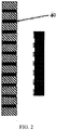
FIG. 2 is a side view showing the porous material with fluidic sample volume introduced into the void space along with the TEM sample substrate, before contact. -
FIG. 3 is a side view showing contact and the transfer of sample from the porous material containing sample to the TEM sample substrate. -
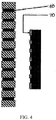
FIG. 4 is a side view showing the TEM sample substrate with transferred sample on the surface before being plunged into a liquid cryogen. - The subject innovation is now described with reference to the drawings, wherein like reference numerals are used to refer to like elements throughout. In the following description, for purposes of explanation, numerous specific details are set forth in order to provide a thorough understanding of the present invention. It may be evident, however, that the present invention may be practiced without these specific details. In other instances, well-known structures and devices are shown in block diagram form in order to facilitate describing the present invention.
- The present invention is a process for preparing samples for cryogenic transmission electron microscopy. A fluidic sample is introduced onto the surface of and/or into the void volume of a hydrophilic porous material. The porous material is brought into contact with a hydrophilic substrate compatible with a cryogenic Transmission Electron Microscope. The porous material is then separated from the substrate, and between contact and separation a portion of sample is transferred from the porous material to the substrate. Upon separation of the porous material and the substrate, the deposited volume of sample now on the substrate is vitrified by plunging the substrate into a cryogen. The volume deposited is appropriate for vitrification for cryo-TEM imaging, eliminating the need to remove excess sample volume, a practice ubiquitous in cryo-TEM sample preparation.
- Cryogenic Transmission Electron Microscopy (cryo-TEM) relies on cryogenic sample preparation of fluidic samples prior to imaging with a TEM, which synergistically provides native images of hydrated materials (e.g., proteins, enzymes, nanomaterial suspensions, etc.) with the resolution advantages of TEM. Cryogenic sample preparation requires the vitrification of the fluidic material, where vitrification is the freezing of a water-based sample fast enough such that water molecules do not crystallize but rather remain amorphous. Crystallization of water results in damage to the molecules/particles/nanomaterials of interest in solution or suspension and result in poor images due to water crystals. The ubiquitous method used to vitrify samples for cryo-TEM has been to pipette fluidic sample onto a TEM sample grid, blot the grid with blotting paper for a finite time period to remove excess sample, and then quickly plunge the grid into a liquid cryogen. The blot is used to reduce the sample volume on the grid (generally to a layer ≤ 100 nm thick) such that the heat transfer rate from the sample fluid to the cryogen vitrifies the sample fluid.
- The blotting process entails pushing a porous blotting paper against the TEM grid, on which a droplet of sample resides. Sample fluid volume from the droplet wicks through the pores of the blotting paper, removing fluid volume from the TEM grid, where the fluid sample volume displaces air within the pores of the paper. The removal of fluid from the grid through the blot is a function of many parameters, including the type of blotting paper used, pre-saturation of blotting paper due to humidity in the ambient environment, force with which the blotting paper is applied against the sample, sample properties, etc. These parameters must be set appropriately such that a layer of sample on the grid is left behind with a thickness of ≤ 100 nm, with the optimal layer thickness being dependent on the sample being analyzed.
- Studies generally rely on multiple replicates of data to build confidence in observations; therefore, multiple TEM grids are conventionally prepared for imaging. This is especially important for Single Particle analysis with cryo-EM, whereby thousands of replicates of a biomacromolecule are captured in images in a variety of random orientations and those 2D images of the biomacromolecule compiled to create a 3D model of the molecular structure. Good repeatability of the blotting process is important so that when blotting parameters are set to prepare grids, the user can be confident that using those same parameters will provide similar, well-vitrified grids when repeating the process. This is important because a large amount of funds, time and effort are spent in the purification of biomacromolecules before cryo-TEM sample preparation can even occur; small volumes of these samples are incredibly valuable and difficult to achieve so poor grids are a large waste of funds and time. Unfortunately, it has been reported that the blotting process is not repeatable. Even commercially-available blotting-based sample preparation robots, which have been developed to offer improved blotting control and repeatability, have been reported to not be repeatable; subsequent samples prepared on the same machine with the same sample material and same blotting parameters, within minutes of each other, can still result in completely different vitrification results. Because of this poor repeatability, and the expense of, and demand for, time for use of high end data collection TEM's, it is generally required that researchers use lower end TEM's and optimize blotting conditions on those "screening TEMs" before imaging samples with a high end TEM; this increases the probability that samples prepared with the optimized parameters will provide quality images that allow for the high resolution creation of a 3D model of the target biomacromolecule. The inefficiency of blotting results in the need for additional screening TEM's (both their purchase and maintenance) and the additional use of valuable sample volume and researcher time to optimize those parameters. It has been reported that some samples have required multiple years in optimization of cryo-TEM sample preparation, clearly showing that new cryo-TEM sample preparation technologies are required to drive cryo-EM to a high throughput technique.
- Other major issues with blotting-based cryo-TEM sample preparation exist. As stated, biomacromolecule samples (often proteins or protein complexes) are incredibly expensive to synthesize; it requires complex processing and often results in small volumes with which imaging can be conducted. Blotting-based cryo-TEM sample preparation has required users to deposit ∼3-5 µL of sample onto the grid by pipetting and the blotting process results ideally with ∼100's pL remaining on the grid. This means more than 99.9% of the valuable sample is blotted away from the grid, which can not be recovered or used again. Sample preparation techniques that can minimize the amount of sample waste would be of huge benefit for cryo-TEM.
- Furthermore, blotting-based sample preparation has required time scales on the order of seconds. For single particle cryo-EM, each biomacromolecule particle (often a protein or protein complex) must be randomly oriented throughout the sample in order to ascertain images of a variety of perspectives of the protein. This variety of two dimensional perspectives provides the ability to construct a three dimensional model of the protein. It has been reported that many proteins will move to the air/water interface, adsorbing to the interface with a preferred orientation, which reduces the number of randomly oriented particles and the ability to calculate a model of the 3D protein structure. It has been reported that if the time interval between the creation of the air/water interface of the sample on the TEM substrate and vitrification is maintained at equal to or less 100-250 msec, the particles will have significantly less ability to move to the air/water interface and adopt a preferred orientation. Furthermore, faster sample preparation will allow for better temporal resolution for studies into dynamic processes, such as biological interactions, e.g. protein-protein binding, or other chemical processes, e.g. reaction intermediates in mixing. There is certainly a major benefit to reducing the time between sample deposition and vitrification when preparing a sample for cryo-TEM.
- Blotless techniques generally suggest that the sample is applied to the grid with a volume small enough that the sample can be vitrified without removal of any excess volume post deposition. Several blotless spray-techniques have been developed and reported upon. With these technologies picoliter to nanoliter volumes of sample are ejected onto the TEM grid prior to vitrification. The ejection has been driven mechanically with piezoelectric pump heads and with pneumatics. These systems eject an appropriate amount of sample, such that removal of excess sample volume is not required. These systems also claim to reduce time from sample interface formation to vitrification such that interfacial adsorption of particles is reduced. These systems utilize fluidic channels to guide the sample fluid and although volumes are dispensed onto the grid that are appropriate for vitrification without blotting, the systems generally require much higher volumes (∼1uL) to work in the practical manifestation of the system. These systems are also very complex and result in systems that are very expensive to manufacture and purchase. These complex systems also only use one spray head, which results in only a small fraction of the grid being covered with sample and fewer potential good areas of vitrified sample ice to capture images. If there is a desire to cover the entire grid, more complexity will be required for the system. Furthermore, they require complex machinery, which results in a large system, which is often difficult to house in sample preparation laboratories that exist in Electron Microscopy facilities. Therefore, there will be a need for additional forms of blotless sample preparation.
- There is another type of blotless cryo-TEM sample preparation that utilizes a microcapillary to deposit sample onto the TEM grid. Two processes are utilized with the microcapillary to deposit sample onto the grid. One entails a microcapillary tube into which sample fluid volume is aspirated. The tip of the tube is brought close to the TEM grid and a high-precision pump pushes the fluid sample forward such that a ∼20 nL "droplet" protrudes from the tip of the microcapillary tube. The droplet contacts the grid and there can be relative motion to get the sample to spread across the grid surface. The droplet is then reaspirated into the microcapillary tube and the grid is plunged for vitrification. The reaspiration results in reduced waste from sample preparation. The second process entails dipping a microcapillary pin into the fluid sample, which when subsequently removed carries a small volume of sample fluid on its surface; the pin tip is then brought into contact with the surface of the TEM grid and written across the surface, transferring sample volume onto the TEM grid. The sample is then plunged into cryogen and vitrified. In both processes a laser and photodiode are utilized to monitor sample layer thickness on the grid post-deposition with the microcapillary; evaporation under controlled temperature is monitored and allowed to occur until sample thickness is measured to be appropriate and is then vitrified. Evaporation can have negative impacts on fluidic samples; it can alter salt concentrations and particle concentrations, which can lead to a conformational and/or structural changes. Furthermore, controlled evaporation monitoring systems add complexity to the sample preparation process and can lead to higher manufacturing costs. Therefore, additional blotless cryo-TEM sample preparation techniques will be of interest.
- The present invention is a blotless technique for depositing fluidic sample onto a substrate for cryo-TEM. A hydrophilic porous material is loaded with a volume of fluidic sample, whereby the sample fills some portion of the void space and covers some part of the surface of the porous material. Introduced fluidic sample volume can match the void space of the porous material, filling up to 100% of the void space of the porous material or even exceed the void space volume, with the sample volume in excess of void volume sticking to/wetting the material surface. Separately, a substrate for cryo-TEM samples is processed to be rendered hydrophilic. The porous material is brought into contact with the surface of the hydrophilic sample substrate. Upon the porous material and sample substrate making contact, there can be shearing motion between the surfaces. The porous material and sample substrate are then separated; this separation can occur in any way, whether normal to the substrate surface or parallel (shear). Due to the hydrophilic nature of the sample substrate, a volume of sample is transferred from the porous material to the substrate. This transfer may occur during the initial contact, relative shearing action between the porous material and substrate (if conducted), and/or separation of the porous material and substrate. The properties of the TEM substrate (geometry, hydrophilicity, etc.), porous material (void space, material, thickness, etc.) and transfer process (with shear or without shear, normal or shear separation between substrate and porous material, volume of sample inserted into porous material) can be set appropriately for the properties of the sample of interest such that a volume is transferred to the substrate that is appropriate for vitrification without any removal of excess sample volume. After separation of the surfaces, the substrate is plunged into a liquid cryogen for sample vitrification.
- Referring now to the drawings, in their simplest description a porous material is a material that contains pores or voids. The material is comprised of a matrix within or throughout which the void space is located. In many cases the matrix is a continuous, solid material, though the matrix can also be comprised of discrete particles or fibers. The pore space is often filled with air or gas, but can also be filled with other fluids.
- For the purpose of this invention, the void space is continuous throughout the matrix; as studied in percolation theory, this allows for fluid to flow from one side through a continuum to the other side of the material. Porous materials, include, but are not limited to: paper, filters, sponges, soil, rock, bone, cork. Porous materials are complex and therefore can be modeled or represented in a variety of ways. To describe this invention, the porous material is shown in two dimensions with channels through the cross section/thickness of the matrix, where the channels can represent the void space of the porous material that can be filled with fluidic sample. This invention is however equally applicable to any type of hydrophilic porous material, whether natively or rendered as such.
- Referring to the TEM sample substrate, generally cryo-TEM samples are deposited onto a TEM grid. The sample is deposited onto a thin carbon film, which is bound to and spread across a grid (film and grid together are colloquially referred to as the TEM grid). The grid component provides mechanical, structural stability while undergoing the sample preparation processes. The grid structure is ∼3mm in diameter and approximately 10-100 µm thick and is manufactured to be a grid pattern across the majority of the structure. While providing structure, the grid is also mostly empty space through which electrons can travel. The carbon film provides a relatively inert structure onto which the sample is deposited, while also allowing electrons to transfer through the film relatively easily; for cryo-TEM the film often contains holes into which the fluidic sample can deposit. The carbon film and substrate are generally rendered hydrophilic utilizing plasma treatment to encourage spreading of the sample across the carbon film surface. This invention is equally applicable to any substrate that is hydrophilic, whether natively or rendered as such, and whether of a grid/film architecture or not. It is also equally applicable to any type of grid material, generally a metal such as copper, gold or nickel, and any thin film used to frame vitrified sample for TEM imaging.
- Referring to the sample, it is generally described here as being fluidic. Many samples for cryo-TEM are suspensions or colloids of particles that are dilute enough to behave like a fluid, generally meaning that they have no resistance to shear stress and under which they will continually deform, or flow. This invention is equally applicable to any fluidic sample with any concentration of any single or multitude of component particles, including proteins, viruses, or other biomolecules, polymers, inorganic particles, and so forth, that will wet, and wick into the pore space of, a hydrophilic porous material.
- In
FIG. 1 , aporous material 10 is depicted in two dimensions as a material with channels running parallel through the material's thickness. Porous materials are complex, so to describe this invention, the porous material is depicted here as a matrix in 2D with channels through the cross section/thickness, rather than a complex three dimensional depiction. In this initial state the pores are empty, filled with ambient air.FIG. 1 depicts the porous material as a flat sheet, however the present invention applies equally to any geometry of porous material. Acarbon film 20 is attached to theTEM grid 30. The carbon film and TEM grid are rendered hydrophilic. - In
FIG. 2 , a volume of sample is deposited into the porous material. Thesample volume 40 occupies some portion of a void space in the pores of the porous material. For ease of depiction sample volume is only shown as occupying some portion of the void volume, however sample also covers some portion of the surface of the porous material.FIG. 2 shows the porous material loaded with a sample volume approximately equal to the void space, however the present invention is equally applicable to any sample volume up to the volume of the void space (100% of void space is full, i.e., porous material is saturated), or a volume of sample even larger than the void space (porous material is over-saturated). - In
FIG. 3 , the porous material is brought into contact with the TEM grid on the carbon film side. This shows the porous material contacting flat onto the carbon, however the present invention applies equally to any contact type, such as the edge of the porous material contacting the carbon. As contact occurs, there may be shearing motion between the porous material and TEM substrate to encourage transfer of sample onto the carbon film. During contact there is sample volume that is transferred from the porous material to theTEM grid 50. Some sample may have sheared completely away from the porous material, and some sample volume may be in contact with both porous material and TEM substrate. - In
FIG. 4 , the porous material is separated from the TEM substrate. Thesample volume 60 in the porous material is now less than the original sample volume 40 (FIG. 2 ), as a portion has been transferred to theTEM substrate 70. The objective is to transfer ∼100's pL to ∼ 1nL of sample onto the TEM grid to achieve an appropriate sample layer thickness for vitrification. It should be noted that volumes depicted being transferred/deposited in the figures may be exaggerated and are for conceptual understanding only. The present invention does apply equally to any sized geometry of porous material, material porosity, porous material type, void space volume, sample volume and so forth. Additionally,sample volume 70 is depicted as having a uniform thickness across the carbon film and pores in the film, however the present invention will often lead to variation in the sample thickness across the grid. - As shown in
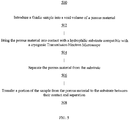
FIG. 5 , anexemplary process 500 includes introducing (502) a fluidic sample into and/or onto a porous material. -
Process 500 brings (504) the porous material into contact with a hydrophilic substrate compatible with a cryogenic Transmission Electron Microscope. -
Process 500 separates (506) the porous material from the substrate. -
Process 500 transfers (508) a portion of the sample from the porous material to the substrate between their contact and separation. - As shown in
FIG. 6 , anotherexemplary process 600 includes loading (602) a hydrophilic porous material with a volume of fluidic sample wherein the fluidic sample fills a portion of a void space and covers part of the surface of the hydrophilic porous material. - Process 600 processes (604) a substrate for cryo-Transmission Electron Microscope samples to be rendered hydrophilic.
-
Process 600 brings (606) the porous material into contact with a surface of the substrate, causing a volume of sample transferred from the hydrophilic porous material to the substrate. -
Process 600 separates (608) a surface of the porous material from the surface of the substrate. -
Process 600 plunges (610) the substrate into a liquid cryogen for sample vitrification. - It would be appreciated by those skilled in the art that various changes and modifications can be made to the illustrated embodiments without departing from the spirit of the present invention. All such modifications and changes are intended to be within the scope of the present invention except as limited by the scope of the appended claims.
Claims (7)
- A method comprising:introducing a fluidic sample onto and/or into a hydrophilic porous material;bringing the porous material into contact with a hydrophilic substrate compatible with a cryogenic Transmission Electron Microscope;separating the porous material from the substrate; andtransferring a portion of the sample from the porous material to the substrate between their contact and separation.
- The method of claim 1 wherein upon separation of the porous material and substrate, the substrate is plunged into liquid cryogen and the fluidic sample is vitrified.
- The method of claim 2 wherein the portion transferred is appropriate for vitrification for cryo- Transmission Electron Microscope imaging, eliminating a need to remove excess sample volume.
- A method comprising:loading a hydrophilic porous material with a volume of fluidic sample wherein the fluidic sample fills a portion of the void space and covers part of the surface of the hydrophilic porous material;processing a substrate for cryo-Transmission Electron Microscope samples to be rendered hydrophilic;bringing the porous material into contact with a surface of the substrate, causing a volume of sample transferred from the hydrophilic porous material to the substrate;separating the porous material from the surface of the substrate; andplunging the substrate into a liquid cryogen for sample vitrification.
- The method of claim 4 wherein the fluidic sample comprises up to 100% of the void space.
- A method comprising a blotless technique for depositing fluidic sample onto a substrate for cryo-Transmission Electron Microscope.
- The method of claim 6 wherein the blotless technique comprises:allowing a volume of fluidic sample to wick into the void space and/or onto the surface of a hydrophilic porous material with a continuous void space;processing a substrate for cryo-Transmission Electron Microscope samples to be rendered hydrophilic;bringing the porous material into contact with a surface of the substrate, and allowing for relative shearing action between the porous material and substrate causing a volume of sample transferred from the hydrophilic porous material to the substrate.separating a surface of the porous material from the surface of the substrate; andplunging the substrate into a liquid cryogen for sample vitrification.
Applications Claiming Priority (1)
| Application Number | Priority Date | Filing Date | Title |
|---|---|---|---|
| US201962805698P | 2019-02-14 | 2019-02-14 |
Publications (2)
| Publication Number | Publication Date |
|---|---|
| EP3696530A1 true EP3696530A1 (en) | 2020-08-19 |
| EP3696530B1 EP3696530B1 (en) | 2024-07-31 |
Family
ID=69740093
Family Applications (1)
| Application Number | Title | Priority Date | Filing Date |
|---|---|---|---|
| EP20157128.8A Active EP3696530B1 (en) | 2019-02-14 | 2020-02-13 | Cryogenic transmission electron microscopy sample preparation |
Country Status (2)
| Country | Link |
|---|---|
| US (1) | US11035766B2 (en) |
| EP (1) | EP3696530B1 (en) |
Families Citing this family (1)
| Publication number | Priority date | Publication date | Assignee | Title |
|---|---|---|---|---|
| WO2025199620A1 (en) * | 2024-03-27 | 2025-10-02 | Neoglacia Inc. | Cryo-electron microscopy sample preparation system, and modules and methods for operating same |
Citations (4)
| Publication number | Priority date | Publication date | Assignee | Title |
|---|---|---|---|---|
| US20120241607A1 (en) * | 2010-03-24 | 2012-09-27 | Arijit Bose | Microfluidic blotless cryo tem device and method |
| WO2013109406A1 (en) * | 2012-01-17 | 2013-07-25 | The Scripps Research Institute | Apparatus and method for producing specimens for electron microscopy |
| EP3062082A1 (en) * | 2015-02-25 | 2016-08-31 | Fei Company | Preparation of sample for charged-particle microscopy |
| WO2018073242A1 (en) * | 2016-10-17 | 2018-04-26 | Universität Basel | Lossless cryo-grid preparation by controlled sample evaporation |
Family Cites Families (14)
| Publication number | Priority date | Publication date | Assignee | Title |
|---|---|---|---|---|
| US4753887A (en) | 1986-08-07 | 1988-06-28 | Regents Of The University Of Minnesota | Controlled environment vitrification system for preparation of liquids |
| NL1017669C2 (en) | 2001-03-22 | 2002-09-24 | Univ Maastricht | Device for the manufacture of preparations for a cryo-electron microscope. |
| AT507079B1 (en) | 2009-01-22 | 2010-02-15 | Leica Mikrosysteme Gmbh | DEVICE AND METHOD FOR PREPARING SAMPLES |
| US9312095B2 (en) | 2010-03-24 | 2016-04-12 | Brown University | Method and system for automating sample preparation for microfluidic cryo TEM |
| EP2805144A4 (en) | 2012-01-17 | 2015-09-09 | Scripps Research Inst | PREPARATION OF ORDERED SAMPLE SETS ON A GRID FOR ELECTRONIC MICROSCOPY |
| US8884248B2 (en) * | 2012-02-13 | 2014-11-11 | Fei Company | Forming a vitrified sample for electron microscopy |
| GB2537579A (en) | 2014-11-07 | 2016-10-26 | Linkam Scient Instr Ltd | Microscopic sample preparation |
| US10309881B2 (en) | 2015-06-30 | 2019-06-04 | The Regents Of The University Of California | Methods and apparatus for preparing aqueous specimens for electron microscopy using volatile surfactants |
| JP6861207B2 (en) | 2015-07-06 | 2021-04-21 | ウニヴェアズィテート バーゼル | Lossless low temperature grid preparation stage for high resolution electron microscope |
| EP3486633B1 (en) | 2015-12-11 | 2021-11-24 | FEI Company | Preparation of cryogenic sample for charged-particle microscopy |
| EP3260839B1 (en) | 2016-06-22 | 2021-01-27 | Universiteit Maastricht | Method for preparing samples for imaging or diffraction experiments under cryogenic conditions |
| WO2020171764A1 (en) | 2019-02-21 | 2020-08-27 | Xiaodong Zou | Cryo-em specimen preparation |
| US10866172B2 (en) | 2019-03-21 | 2020-12-15 | Neptune Fluid Flow Systems LLC | System and method for preparing cryo-em grids |
| WO2020191123A1 (en) | 2019-03-21 | 2020-09-24 | Neptune Fluid Flow Systems | System and method for preparing cryo-em grids |
-
2020
- 2020-02-13 US US16/790,367 patent/US11035766B2/en active Active
- 2020-02-13 EP EP20157128.8A patent/EP3696530B1/en active Active
Patent Citations (4)
| Publication number | Priority date | Publication date | Assignee | Title |
|---|---|---|---|---|
| US20120241607A1 (en) * | 2010-03-24 | 2012-09-27 | Arijit Bose | Microfluidic blotless cryo tem device and method |
| WO2013109406A1 (en) * | 2012-01-17 | 2013-07-25 | The Scripps Research Institute | Apparatus and method for producing specimens for electron microscopy |
| EP3062082A1 (en) * | 2015-02-25 | 2016-08-31 | Fei Company | Preparation of sample for charged-particle microscopy |
| WO2018073242A1 (en) * | 2016-10-17 | 2018-04-26 | Universität Basel | Lossless cryo-grid preparation by controlled sample evaporation |
Non-Patent Citations (1)
| Title |
|---|
| RAZINKOV IVAN ET AL: "A new method for vitrifying samples for cryoEM", JOURNAL OF STRUCTURAL BIOLOGY, ACADEMIC PRESS, UNITED STATES, vol. 195, no. 2, 8 June 2016 (2016-06-08), pages 190 - 198, XP029627270, ISSN: 1047-8477, DOI: 10.1016/J.JSB.2016.06.001 * |
Also Published As
| Publication number | Publication date |
|---|---|
| US20200264079A1 (en) | 2020-08-20 |
| EP3696530B1 (en) | 2024-07-31 |
| US11035766B2 (en) | 2021-06-15 |
Similar Documents
| Publication | Publication Date | Title |
|---|---|---|
| JP4361271B2 (en) | Instruments for assay, synthesis, and storage, and methods of making, using, and operating the same | |
| US11703429B2 (en) | Cryogenic transmission electron microscopy sample preparation | |
| US9968903B2 (en) | Apparatus for assay, synthesis and storage, and methods of manufacture, use, and manipulation thereof | |
| US9952128B2 (en) | Preparation of specimen arrays on an EM grid | |
| EP0846124B1 (en) | Chemical, biochemical and biological processing in thin films | |
| US7214540B2 (en) | Method for screening crystallization conditions in solution crystal growth | |
| US20020001546A1 (en) | Methods for screening substances in a microwell array | |
| WO2007022026A2 (en) | Apparatus for assay, synthesis and storage, and methods of manufacture, use, and manipulation thereof | |
| AU4197300A (en) | Method for screening crystallization conditions in solution crystal growth | |
| WO2020171764A1 (en) | Cryo-em specimen preparation | |
| WO2013109406A1 (en) | Apparatus and method for producing specimens for electron microscopy | |
| EP3696530B1 (en) | Cryogenic transmission electron microscopy sample preparation | |
| EP4105632A1 (en) | Cryogenic transmission electron microscopy sample preparation | |
| JP2005513454A (en) | FFE array dispenser | |
| JP2005513472A (en) | Analyzer and analysis method | |
| EP3523820B1 (en) | Sample holder for mass spectrometry analysis in maldi mode, production and use of the sample holder | |
| EP3502654A1 (en) | Method for applying liquids to a substrate | |
| DE102004005100A1 (en) | Process for the preparation of solid phase bound bioreagents | |
| EP1701159A2 (en) | Method for screening crystallization conditions in protein solution crystal growth |
Legal Events
| Date | Code | Title | Description |
|---|---|---|---|
| PUAI | Public reference made under article 153(3) epc to a published international application that has entered the european phase |
Free format text: ORIGINAL CODE: 0009012 |
|
| STAA | Information on the status of an ep patent application or granted ep patent |
Free format text: STATUS: REQUEST FOR EXAMINATION WAS MADE |
|
| 17P | Request for examination filed |
Effective date: 20200213 |
|
| AK | Designated contracting states |
Kind code of ref document: A1 Designated state(s): AL AT BE BG CH CY CZ DE DK EE ES FI FR GB GR HR HU IE IS IT LI LT LU LV MC MK MT NL NO PL PT RO RS SE SI SK SM TR |
|
| AX | Request for extension of the european patent |
Extension state: BA ME |
|
| STAA | Information on the status of an ep patent application or granted ep patent |
Free format text: STATUS: EXAMINATION IS IN PROGRESS |
|
| 17Q | First examination report despatched |
Effective date: 20220718 |
|
| GRAP | Despatch of communication of intention to grant a patent |
Free format text: ORIGINAL CODE: EPIDOSNIGR1 |
|
| STAA | Information on the status of an ep patent application or granted ep patent |
Free format text: STATUS: GRANT OF PATENT IS INTENDED |
|
| RIC1 | Information provided on ipc code assigned before grant |
Ipc: G01N 1/28 20060101ALN20240221BHEP Ipc: G01N 1/42 20060101AFI20240221BHEP |
|
| INTG | Intention to grant announced |
Effective date: 20240313 |
|
| GRAS | Grant fee paid |
Free format text: ORIGINAL CODE: EPIDOSNIGR3 |
|
| GRAA | (expected) grant |
Free format text: ORIGINAL CODE: 0009210 |
|
| STAA | Information on the status of an ep patent application or granted ep patent |
Free format text: STATUS: THE PATENT HAS BEEN GRANTED |
|
| AK | Designated contracting states |
Kind code of ref document: B1 Designated state(s): AL AT BE BG CH CY CZ DE DK EE ES FI FR GB GR HR HU IE IS IT LI LT LU LV MC MK MT NL NO PL PT RO RS SE SI SK SM TR |
|
| REG | Reference to a national code |
Ref country code: CH Ref legal event code: EP Ref country code: GB Ref legal event code: FG4D |
|
| REG | Reference to a national code |
Ref country code: DE Ref legal event code: R096 Ref document number: 602020034710 Country of ref document: DE |
|
| REG | Reference to a national code |
Ref country code: IE Ref legal event code: FG4D |
|
| REG | Reference to a national code |
Ref country code: LT Ref legal event code: MG9D |
|
| REG | Reference to a national code |
Ref country code: NL Ref legal event code: MP Effective date: 20240731 |
|
| PG25 | Lapsed in a contracting state [announced via postgrant information from national office to epo] |
Ref country code: PT Free format text: LAPSE BECAUSE OF FAILURE TO SUBMIT A TRANSLATION OF THE DESCRIPTION OR TO PAY THE FEE WITHIN THE PRESCRIBED TIME-LIMIT Effective date: 20241202 |
|
| REG | Reference to a national code |
Ref country code: AT Ref legal event code: MK05 Ref document number: 1708904 Country of ref document: AT Kind code of ref document: T Effective date: 20240731 |
|
| PG25 | Lapsed in a contracting state [announced via postgrant information from national office to epo] |
Ref country code: PT Free format text: LAPSE BECAUSE OF FAILURE TO SUBMIT A TRANSLATION OF THE DESCRIPTION OR TO PAY THE FEE WITHIN THE PRESCRIBED TIME-LIMIT Effective date: 20241202 |
|
| PG25 | Lapsed in a contracting state [announced via postgrant information from national office to epo] |
Ref country code: NO Free format text: LAPSE BECAUSE OF FAILURE TO SUBMIT A TRANSLATION OF THE DESCRIPTION OR TO PAY THE FEE WITHIN THE PRESCRIBED TIME-LIMIT Effective date: 20241031 |
|
| PG25 | Lapsed in a contracting state [announced via postgrant information from national office to epo] |
Ref country code: NL Free format text: LAPSE BECAUSE OF FAILURE TO SUBMIT A TRANSLATION OF THE DESCRIPTION OR TO PAY THE FEE WITHIN THE PRESCRIBED TIME-LIMIT Effective date: 20240731 Ref country code: FI Free format text: LAPSE BECAUSE OF FAILURE TO SUBMIT A TRANSLATION OF THE DESCRIPTION OR TO PAY THE FEE WITHIN THE PRESCRIBED TIME-LIMIT Effective date: 20240731 Ref country code: PL Free format text: LAPSE BECAUSE OF FAILURE TO SUBMIT A TRANSLATION OF THE DESCRIPTION OR TO PAY THE FEE WITHIN THE PRESCRIBED TIME-LIMIT Effective date: 20240731 Ref country code: GR Free format text: LAPSE BECAUSE OF FAILURE TO SUBMIT A TRANSLATION OF THE DESCRIPTION OR TO PAY THE FEE WITHIN THE PRESCRIBED TIME-LIMIT Effective date: 20241101 |
|
| PG25 | Lapsed in a contracting state [announced via postgrant information from national office to epo] |
Ref country code: BG Free format text: LAPSE BECAUSE OF FAILURE TO SUBMIT A TRANSLATION OF THE DESCRIPTION OR TO PAY THE FEE WITHIN THE PRESCRIBED TIME-LIMIT Effective date: 20240731 |
|
| PG25 | Lapsed in a contracting state [announced via postgrant information from national office to epo] |
Ref country code: LV Free format text: LAPSE BECAUSE OF FAILURE TO SUBMIT A TRANSLATION OF THE DESCRIPTION OR TO PAY THE FEE WITHIN THE PRESCRIBED TIME-LIMIT Effective date: 20240731 |
|
| PG25 | Lapsed in a contracting state [announced via postgrant information from national office to epo] |
Ref country code: IS Free format text: LAPSE BECAUSE OF FAILURE TO SUBMIT A TRANSLATION OF THE DESCRIPTION OR TO PAY THE FEE WITHIN THE PRESCRIBED TIME-LIMIT Effective date: 20241130 Ref country code: AT Free format text: LAPSE BECAUSE OF FAILURE TO SUBMIT A TRANSLATION OF THE DESCRIPTION OR TO PAY THE FEE WITHIN THE PRESCRIBED TIME-LIMIT Effective date: 20240731 |
|
| PG25 | Lapsed in a contracting state [announced via postgrant information from national office to epo] |
Ref country code: HR Free format text: LAPSE BECAUSE OF FAILURE TO SUBMIT A TRANSLATION OF THE DESCRIPTION OR TO PAY THE FEE WITHIN THE PRESCRIBED TIME-LIMIT Effective date: 20240731 |
|
| PG25 | Lapsed in a contracting state [announced via postgrant information from national office to epo] |
Ref country code: ES Free format text: LAPSE BECAUSE OF FAILURE TO SUBMIT A TRANSLATION OF THE DESCRIPTION OR TO PAY THE FEE WITHIN THE PRESCRIBED TIME-LIMIT Effective date: 20240731 Ref country code: RS Free format text: LAPSE BECAUSE OF FAILURE TO SUBMIT A TRANSLATION OF THE DESCRIPTION OR TO PAY THE FEE WITHIN THE PRESCRIBED TIME-LIMIT Effective date: 20241031 |
|
| PG25 | Lapsed in a contracting state [announced via postgrant information from national office to epo] |
Ref country code: RS Free format text: LAPSE BECAUSE OF FAILURE TO SUBMIT A TRANSLATION OF THE DESCRIPTION OR TO PAY THE FEE WITHIN THE PRESCRIBED TIME-LIMIT Effective date: 20241031 Ref country code: PL Free format text: LAPSE BECAUSE OF FAILURE TO SUBMIT A TRANSLATION OF THE DESCRIPTION OR TO PAY THE FEE WITHIN THE PRESCRIBED TIME-LIMIT Effective date: 20240731 Ref country code: NO Free format text: LAPSE BECAUSE OF FAILURE TO SUBMIT A TRANSLATION OF THE DESCRIPTION OR TO PAY THE FEE WITHIN THE PRESCRIBED TIME-LIMIT Effective date: 20241031 Ref country code: NL Free format text: LAPSE BECAUSE OF FAILURE TO SUBMIT A TRANSLATION OF THE DESCRIPTION OR TO PAY THE FEE WITHIN THE PRESCRIBED TIME-LIMIT Effective date: 20240731 Ref country code: LV Free format text: LAPSE BECAUSE OF FAILURE TO SUBMIT A TRANSLATION OF THE DESCRIPTION OR TO PAY THE FEE WITHIN THE PRESCRIBED TIME-LIMIT Effective date: 20240731 Ref country code: IS Free format text: LAPSE BECAUSE OF FAILURE TO SUBMIT A TRANSLATION OF THE DESCRIPTION OR TO PAY THE FEE WITHIN THE PRESCRIBED TIME-LIMIT Effective date: 20241130 Ref country code: HR Free format text: LAPSE BECAUSE OF FAILURE TO SUBMIT A TRANSLATION OF THE DESCRIPTION OR TO PAY THE FEE WITHIN THE PRESCRIBED TIME-LIMIT Effective date: 20240731 Ref country code: GR Free format text: LAPSE BECAUSE OF FAILURE TO SUBMIT A TRANSLATION OF THE DESCRIPTION OR TO PAY THE FEE WITHIN THE PRESCRIBED TIME-LIMIT Effective date: 20241101 Ref country code: FI Free format text: LAPSE BECAUSE OF FAILURE TO SUBMIT A TRANSLATION OF THE DESCRIPTION OR TO PAY THE FEE WITHIN THE PRESCRIBED TIME-LIMIT Effective date: 20240731 Ref country code: ES Free format text: LAPSE BECAUSE OF FAILURE TO SUBMIT A TRANSLATION OF THE DESCRIPTION OR TO PAY THE FEE WITHIN THE PRESCRIBED TIME-LIMIT Effective date: 20240731 Ref country code: BG Free format text: LAPSE BECAUSE OF FAILURE TO SUBMIT A TRANSLATION OF THE DESCRIPTION OR TO PAY THE FEE WITHIN THE PRESCRIBED TIME-LIMIT Effective date: 20240731 Ref country code: AT Free format text: LAPSE BECAUSE OF FAILURE TO SUBMIT A TRANSLATION OF THE DESCRIPTION OR TO PAY THE FEE WITHIN THE PRESCRIBED TIME-LIMIT Effective date: 20240731 |
|
| PG25 | Lapsed in a contracting state [announced via postgrant information from national office to epo] |
Ref country code: DK Free format text: LAPSE BECAUSE OF FAILURE TO SUBMIT A TRANSLATION OF THE DESCRIPTION OR TO PAY THE FEE WITHIN THE PRESCRIBED TIME-LIMIT Effective date: 20240731 Ref country code: RO Free format text: LAPSE BECAUSE OF FAILURE TO SUBMIT A TRANSLATION OF THE DESCRIPTION OR TO PAY THE FEE WITHIN THE PRESCRIBED TIME-LIMIT Effective date: 20240731 Ref country code: SM Free format text: LAPSE BECAUSE OF FAILURE TO SUBMIT A TRANSLATION OF THE DESCRIPTION OR TO PAY THE FEE WITHIN THE PRESCRIBED TIME-LIMIT Effective date: 20240731 |
|
| PG25 | Lapsed in a contracting state [announced via postgrant information from national office to epo] |
Ref country code: EE Free format text: LAPSE BECAUSE OF FAILURE TO SUBMIT A TRANSLATION OF THE DESCRIPTION OR TO PAY THE FEE WITHIN THE PRESCRIBED TIME-LIMIT Effective date: 20240731 |
|
| PG25 | Lapsed in a contracting state [announced via postgrant information from national office to epo] |
Ref country code: CZ Free format text: LAPSE BECAUSE OF FAILURE TO SUBMIT A TRANSLATION OF THE DESCRIPTION OR TO PAY THE FEE WITHIN THE PRESCRIBED TIME-LIMIT Effective date: 20240731 |
|
| PG25 | Lapsed in a contracting state [announced via postgrant information from national office to epo] |
Ref country code: IT Free format text: LAPSE BECAUSE OF FAILURE TO SUBMIT A TRANSLATION OF THE DESCRIPTION OR TO PAY THE FEE WITHIN THE PRESCRIBED TIME-LIMIT Effective date: 20240731 Ref country code: SK Free format text: LAPSE BECAUSE OF FAILURE TO SUBMIT A TRANSLATION OF THE DESCRIPTION OR TO PAY THE FEE WITHIN THE PRESCRIBED TIME-LIMIT Effective date: 20240731 |
|
| REG | Reference to a national code |
Ref country code: DE Ref legal event code: R097 Ref document number: 602020034710 Country of ref document: DE |
|
| PLBE | No opposition filed within time limit |
Free format text: ORIGINAL CODE: 0009261 |
|
| STAA | Information on the status of an ep patent application or granted ep patent |
Free format text: STATUS: NO OPPOSITION FILED WITHIN TIME LIMIT |
|
| 26N | No opposition filed |
Effective date: 20250501 |
|
| PG25 | Lapsed in a contracting state [announced via postgrant information from national office to epo] |
Ref country code: SE Free format text: LAPSE BECAUSE OF FAILURE TO SUBMIT A TRANSLATION OF THE DESCRIPTION OR TO PAY THE FEE WITHIN THE PRESCRIBED TIME-LIMIT Effective date: 20240731 |
|
| PG25 | Lapsed in a contracting state [announced via postgrant information from national office to epo] |
Ref country code: MC Free format text: LAPSE BECAUSE OF FAILURE TO SUBMIT A TRANSLATION OF THE DESCRIPTION OR TO PAY THE FEE WITHIN THE PRESCRIBED TIME-LIMIT Effective date: 20240731 |
|
| REG | Reference to a national code |
Ref country code: CH Ref legal event code: PL |
|
| PG25 | Lapsed in a contracting state [announced via postgrant information from national office to epo] |
Ref country code: LU Free format text: LAPSE BECAUSE OF NON-PAYMENT OF DUE FEES Effective date: 20250213 |
|
| PG25 | Lapsed in a contracting state [announced via postgrant information from national office to epo] |
Ref country code: CH Free format text: LAPSE BECAUSE OF NON-PAYMENT OF DUE FEES Effective date: 20250228 |
|
| REG | Reference to a national code |
Ref country code: BE Ref legal event code: MM Effective date: 20250228 |
|
| PG25 | Lapsed in a contracting state [announced via postgrant information from national office to epo] |
Ref country code: FR Free format text: LAPSE BECAUSE OF NON-PAYMENT OF DUE FEES Effective date: 20250228 |
|
| PG25 | Lapsed in a contracting state [announced via postgrant information from national office to epo] |
Ref country code: BE Free format text: LAPSE BECAUSE OF NON-PAYMENT OF DUE FEES Effective date: 20250228 |
|
| PG25 | Lapsed in a contracting state [announced via postgrant information from national office to epo] |
Ref country code: IE Free format text: LAPSE BECAUSE OF NON-PAYMENT OF DUE FEES Effective date: 20250213 |
|
| PGFP | Annual fee paid to national office [announced via postgrant information from national office to epo] |
Ref country code: GB Payment date: 20260227 Year of fee payment: 7 |
|
| PGFP | Annual fee paid to national office [announced via postgrant information from national office to epo] |
Ref country code: DE Payment date: 20260227 Year of fee payment: 7 |