EP3696440A1 - Non-metallic orifice plate - Google Patents
Non-metallic orifice plate Download PDFInfo
- Publication number
- EP3696440A1 EP3696440A1 EP19214552.2A EP19214552A EP3696440A1 EP 3696440 A1 EP3696440 A1 EP 3696440A1 EP 19214552 A EP19214552 A EP 19214552A EP 3696440 A1 EP3696440 A1 EP 3696440A1
- Authority
- EP
- European Patent Office
- Prior art keywords
- wear
- orifice plate
- diameter surface
- inner diameter
- resistant
- Prior art date
- Legal status (The legal status is an assumption and is not a legal conclusion. Google has not performed a legal analysis and makes no representation as to the accuracy of the status listed.)
- Granted
Links
Images


Classifications
-
- F—MECHANICAL ENGINEERING; LIGHTING; HEATING; WEAPONS; BLASTING
- F16—ENGINEERING ELEMENTS AND UNITS; GENERAL MEASURES FOR PRODUCING AND MAINTAINING EFFECTIVE FUNCTIONING OF MACHINES OR INSTALLATIONS; THERMAL INSULATION IN GENERAL
- F16F—SPRINGS; SHOCK-ABSORBERS; MEANS FOR DAMPING VIBRATION
- F16F9/00—Springs, vibration-dampers, shock-absorbers, or similarly-constructed movement-dampers using a fluid or the equivalent as damping medium
- F16F9/32—Details
- F16F9/34—Special valve constructions; Shape or construction of throttling passages
- F16F9/342—Throttling passages operating with metering pins
-
- B—PERFORMING OPERATIONS; TRANSPORTING
- B64—AIRCRAFT; AVIATION; COSMONAUTICS
- B64C—AEROPLANES; HELICOPTERS
- B64C25/00—Alighting gear
- B64C25/32—Alighting gear characterised by elements which contact the ground or similar surface
- B64C25/58—Arrangements or adaptations of shock-absorbers or springs
- B64C25/60—Oleo legs
-
- F—MECHANICAL ENGINEERING; LIGHTING; HEATING; WEAPONS; BLASTING
- F16—ENGINEERING ELEMENTS AND UNITS; GENERAL MEASURES FOR PRODUCING AND MAINTAINING EFFECTIVE FUNCTIONING OF MACHINES OR INSTALLATIONS; THERMAL INSULATION IN GENERAL
- F16C—SHAFTS; FLEXIBLE SHAFTS; ELEMENTS OR CRANKSHAFT MECHANISMS; ROTARY BODIES OTHER THAN GEARING ELEMENTS; BEARINGS
- F16C17/00—Sliding-contact bearings for exclusively rotary movement
- F16C17/04—Sliding-contact bearings for exclusively rotary movement for axial load only
-
- F—MECHANICAL ENGINEERING; LIGHTING; HEATING; WEAPONS; BLASTING
- F16—ENGINEERING ELEMENTS AND UNITS; GENERAL MEASURES FOR PRODUCING AND MAINTAINING EFFECTIVE FUNCTIONING OF MACHINES OR INSTALLATIONS; THERMAL INSULATION IN GENERAL
- F16C—SHAFTS; FLEXIBLE SHAFTS; ELEMENTS OR CRANKSHAFT MECHANISMS; ROTARY BODIES OTHER THAN GEARING ELEMENTS; BEARINGS
- F16C33/00—Parts of bearings; Special methods for making bearings or parts thereof
- F16C33/02—Parts of sliding-contact bearings
- F16C33/04—Brasses; Bushes; Linings
- F16C33/20—Sliding surface consisting mainly of plastics
- F16C33/208—Methods of manufacture, e.g. shaping, applying coatings
-
- F—MECHANICAL ENGINEERING; LIGHTING; HEATING; WEAPONS; BLASTING
- F16—ENGINEERING ELEMENTS AND UNITS; GENERAL MEASURES FOR PRODUCING AND MAINTAINING EFFECTIVE FUNCTIONING OF MACHINES OR INSTALLATIONS; THERMAL INSULATION IN GENERAL
- F16F—SPRINGS; SHOCK-ABSORBERS; MEANS FOR DAMPING VIBRATION
- F16F15/00—Suppression of vibrations in systems; Means or arrangements for avoiding or reducing out-of-balance forces, e.g. due to motion
- F16F15/02—Suppression of vibrations of non-rotating, e.g. reciprocating systems; Suppression of vibrations of rotating systems by use of members not moving with the rotating systems
- F16F15/023—Suppression of vibrations of non-rotating, e.g. reciprocating systems; Suppression of vibrations of rotating systems by use of members not moving with the rotating systems using fluid means
- F16F15/0232—Suppression of vibrations of non-rotating, e.g. reciprocating systems; Suppression of vibrations of rotating systems by use of members not moving with the rotating systems using fluid means with at least one gas spring
-
- F—MECHANICAL ENGINEERING; LIGHTING; HEATING; WEAPONS; BLASTING
- F16—ENGINEERING ELEMENTS AND UNITS; GENERAL MEASURES FOR PRODUCING AND MAINTAINING EFFECTIVE FUNCTIONING OF MACHINES OR INSTALLATIONS; THERMAL INSULATION IN GENERAL
- F16C—SHAFTS; FLEXIBLE SHAFTS; ELEMENTS OR CRANKSHAFT MECHANISMS; ROTARY BODIES OTHER THAN GEARING ELEMENTS; BEARINGS
- F16C2208/00—Plastics; Synthetic resins, e.g. rubbers
- F16C2208/02—Plastics; Synthetic resins, e.g. rubbers comprising fillers, fibres
-
- F—MECHANICAL ENGINEERING; LIGHTING; HEATING; WEAPONS; BLASTING
- F16—ENGINEERING ELEMENTS AND UNITS; GENERAL MEASURES FOR PRODUCING AND MAINTAINING EFFECTIVE FUNCTIONING OF MACHINES OR INSTALLATIONS; THERMAL INSULATION IN GENERAL
- F16C—SHAFTS; FLEXIBLE SHAFTS; ELEMENTS OR CRANKSHAFT MECHANISMS; ROTARY BODIES OTHER THAN GEARING ELEMENTS; BEARINGS
- F16C2208/00—Plastics; Synthetic resins, e.g. rubbers
- F16C2208/80—Thermosetting resins
- F16C2208/82—Composites, i.e. fibre reinforced thermosetting resins
-
- F—MECHANICAL ENGINEERING; LIGHTING; HEATING; WEAPONS; BLASTING
- F16—ENGINEERING ELEMENTS AND UNITS; GENERAL MEASURES FOR PRODUCING AND MAINTAINING EFFECTIVE FUNCTIONING OF MACHINES OR INSTALLATIONS; THERMAL INSULATION IN GENERAL
- F16C—SHAFTS; FLEXIBLE SHAFTS; ELEMENTS OR CRANKSHAFT MECHANISMS; ROTARY BODIES OTHER THAN GEARING ELEMENTS; BEARINGS
- F16C2326/00—Articles relating to transporting
- F16C2326/01—Parts of vehicles in general
- F16C2326/05—Vehicle suspensions, e.g. bearings, pivots or connecting rods used therein
-
- F—MECHANICAL ENGINEERING; LIGHTING; HEATING; WEAPONS; BLASTING
- F16—ENGINEERING ELEMENTS AND UNITS; GENERAL MEASURES FOR PRODUCING AND MAINTAINING EFFECTIVE FUNCTIONING OF MACHINES OR INSTALLATIONS; THERMAL INSULATION IN GENERAL
- F16F—SPRINGS; SHOCK-ABSORBERS; MEANS FOR DAMPING VIBRATION
- F16F2224/00—Materials; Material properties
- F16F2224/005—Combined materials of same basic nature but differing characteristics
-
- F—MECHANICAL ENGINEERING; LIGHTING; HEATING; WEAPONS; BLASTING
- F16—ENGINEERING ELEMENTS AND UNITS; GENERAL MEASURES FOR PRODUCING AND MAINTAINING EFFECTIVE FUNCTIONING OF MACHINES OR INSTALLATIONS; THERMAL INSULATION IN GENERAL
- F16F—SPRINGS; SHOCK-ABSORBERS; MEANS FOR DAMPING VIBRATION
- F16F2224/00—Materials; Material properties
- F16F2224/02—Materials; Material properties solids
- F16F2224/0291—PTFE
-
- F—MECHANICAL ENGINEERING; LIGHTING; HEATING; WEAPONS; BLASTING
- F16—ENGINEERING ELEMENTS AND UNITS; GENERAL MEASURES FOR PRODUCING AND MAINTAINING EFFECTIVE FUNCTIONING OF MACHINES OR INSTALLATIONS; THERMAL INSULATION IN GENERAL
- F16F—SPRINGS; SHOCK-ABSORBERS; MEANS FOR DAMPING VIBRATION
- F16F2226/00—Manufacturing; Treatments
- F16F2226/04—Assembly or fixing methods; methods to form or fashion parts
Definitions
- the present disclosure relates to shock strut systems, and more specifically, to orifice plates for shock struts.
- Shock absorbing devices are used in a wide variety of vehicle suspension systems for controlling motion of the vehicle and its tires with respect to the ground and for reducing transmission of transient forces from the ground to the vehicle.
- Shock absorbing struts are a common component in most aircraft landing gear assemblies. Shock struts control motion of the landing gear, and absorb and damp loads imposed on the gear during landing, taxiing, braking, and takeoff.
- a shock strut generally accomplishes these functions by compressing a fluid within a sealed chamber formed by hollow telescoping cylinders.
- the fluid generally includes both a gas and a liquid, such as hydraulic fluid or oil.
- One type of shock strut generally utilizes an "air-over-oil" arrangement wherein a trapped volume of gas is compressed as the shock strut is axially compressed, and a volume of oil is metered through an orifice.
- the gas acts as an energy storage device, similar to a spring, so that upon termination of a compressing force the shock strut returns to its original length.
- Shock struts also dissipate energy by passing the oil through the orifice so that as the shock absorber is compressed or extended, its rate of motion is limited by the damping action from the interaction of the orifice and the oil.
- a non-metallic orifice plate comprising a wear-resistant inner diameter surface, an outer diameter surface, a first side surface extending between the wear-resistant inner diameter surface and the outer diameter surface, and a second side surface extending between the wear-resistant inner diameter surface and the outer diameter surface, the second side surface disposed opposite the non-metallic orifice plate from the first side surface, wherein the non-metallic orifice plate comprises at least one of a thermoplastic and a thermoset carbon fiber reinforced composite.
- the non-metallic orifice plate comprises a body portion comprising a first material.
- the wear-resistant inner diameter surface comprises a second material.
- the first material comprises the thermoplastic and/or the thermoset carbon fiber reinforced composite.
- the second material comprises a polytetrafluoroethylene.
- the non-metallic orifice plate further comprises a wear insert disposed in the body portion of the non-metallic orifice plate.
- the wear insert defines the wear-resistant inner diameter surface.
- the orifice further comprises a wear-resistant coating comprising the second material disposed on the body portion and defining the wear-resistant inner diameter surface.
- a shock strut comprising a strut cylinder, a strut piston operatively coupled to the strut cylinder, a non-metallic orifice plate, and a metering pin extending through the non-metallic orifice plate, wherein the non-metallic orifice plate comprises a wear-resistant inner diameter surface, an outer diameter surface, a first side surface extending between the wear-resistant inner diameter surface and the outer diameter surface, and a second side surface extending between the wear-resistant inner diameter surface and the outer diameter surface, the second side surface disposed opposite the non-metallic orifice plate from the first side surface, wherein the non-metallic orifice plate comprises at least one of a thermoplastic and a thermoset carbon fiber reinforced composite.
- the non-metallic orifice plate comprises a body portion comprising a first material.
- the wear-resistant inner diameter surface comprises a second material.
- the first material comprises at least one of the thermoplastic and the thermoset carbon fiber reinforced composite.
- the second material comprises a polytetrafluoroethylene.
- the non-metallic orifice plate further comprises a wear insert disposed in the body portion of the non-metallic orifice plate, wherein the wear insert defines the wear-resistant inner diameter surface.
- the non-metallic orifice plate further comprises a wear-resistant coating comprising the second material disposed on the body portion and defining the wear-resistant inner diameter surface.
- a method for manufacturing a non-metallic orifice plate comprising forming a body portion of the non-metallic orifice plate, and forming a wear-resistant inner diameter surface of the non-metallic orifice plate, wherein the body portion comprises a first material and the wear-resistant inner diameter surface comprises a second material.
- the wear-resistant inner diameter surface is formed by applying a wear-resistant coating to an inner diameter surface of the body portion.
- the wear-resistant inner diameter surface is formed by applying a wear-resistant coating to an inner diameter surface of the body portion.
- the first material comprises a polytetrafluoroethylene.
- the second material comprises at least one of a thermoplastic or a thermoset carbon fiber reinforced composite.
- a 100% non-metallic orifice plate may comprise a wear-resistant inner diameter surface, an outer diameter surface, a first side surface extending between the inner diameter surface and the outer diameter surface, and a second side surface extending between the inner diameter surface and the outer diameter surface, the second side surface disposed opposite the non-metallic orifice plate from the first side surface.
- the disclosed non-metallic orifice plate may provide weight-savings, while maintaining wear resistance at the inner diameter surface.
- Shock strut 100 may be configured to absorb and dampen forces transmitted between a vehicle and the ground.
- Shock strut 100 may comprise a strut piston 112 and a strut cylinder 113.
- Strut cylinder 113 may be configured to receive strut piston 112 in a manner that allows the two components to telescope together and absorb and dampen forces transmitted between a first end 101 (also referred to herein as a proximal end) and a second end 102 (also referred to herein as a distal end) of shock strut 100.
- a fluid such as a hydraulic fluid, and oil, and/or a gas is located within strut cylinder 113.
- Strut cylinder 113 and strut piston 112 may, for example, be configured to seal such that liquid contained within strut cylinder 113 is prevented from leaking as strut piston 112 translates relative to strut cylinder 113.
- strut cylinder 113 may be configured to contain a gas such as nitrogen gas or air.
- Shock strut 100 may comprise a proximal end 101 and a distal end 102, wherein the distal end 102 is opposite the proximal end 101, the distal end 102 being the end of the shock strut closest to a wheel or wheel assembly of a vehicle.
- a gas chamber may be positioned above an oil chamber (referred to as an "air-over-oil” arrangement) or vice versa, where the term “above” in this context means in the direction of the proximal end 101 of the shock strut 100.
- strut cylinder 113 and strut piston 112 may be sealed such that gas is prevented from leaking as strut piston 112 moves relative to strut cylinder 113.
- shock strut 100 may comprise a pressurized environment within strut cylinder 113.
- the strut cylinder 113 may comprise a hollow circular tube having various components disposed within.
- Strut cylinder 113 may comprise a strut chamber 118.
- Strut cylinder 113 may comprise an orifice support tube 140.
- Orifice support tube 140 may comprise a hollow tube having a plurality of orifices through which oil or gas may travel.
- orifice support tube 140 may comprise a tube channel 142 in fluid communication with strut chamber 118.
- strut chamber 118 may comprise tube channel 142 defined by orifice support tube 140.
- Various fluids may be disposed in strut chamber 118. Air may be disposed within strut chamber 118. Oil may be disposed within strut chamber 118, whether alone or in combination with a gas such as air or nitrogen gas.
- strut piston 112 may comprise a hollow circular tube. At least a portion of strut piston 112 may be received by open end 115 of strut cylinder 113. Strut piston 112 may comprise a metering pin 110. Metering pin 110 may move with strut piston 112 with respect to strut cylinder 113. Metering pin 110 may be received in orifice support tube 140. Strut piston 112 may be reciprocally received within the strut cylinder 113. In various embodiments, strut piston 112 may be reciprocally received within strut cylinder 113 in a concentric relationship with and between the strut cylinder 113 and orifice support tube 140. In various embodiments, one or more bearings may be disposed between strut cylinder 113 and strut piston 112 against which the strut piston 112 slides.
- metering pin 110 may comprise a first end 131 (also referred to herein as a proximal end) and a second end 132 (also referred to herein as a distal end). Second end 132 may be coupled to strut piston 112. First end 131 may be received into orifice support tube 140.
- the strut cylinder 113 may comprise a non-metallic orifice plate 150 (also referred to herein as an orifice plate). Metering pin 110 may be received by orifice plate 150. Metering pin 110 may slide against an inner diameter (ID) surface of orifice plate 150. In this regard, metering pin 110 may extend through orifice plate 150.
- orifice plate 150 installed in shock strut 100 is illustrated, in accordance with various embodiments.
- orifice plate 150 may be coupled to orifice support tube 140.
- Orifice plate 150 may be disposed in orifice support tube 140.
- the outer portion (i.e., at outer diameter (OD) surface 162) of orifice plate 150 may be coupled to orifice support tube 140.
- a threaded fastener 144 may be coupled to the open end 141 of orifice support tube 140.
- Orifice plate 150 may float between threaded fastener 144 and orifice support tube 140.
- Orifice plate 150 may be comprised of a non-metallic material, such as a thermoplastic or a thermoset carbon fiber reinforced composite, for example. Orifice plate 150 may comprise an inner diameter (ID) surface 161 and an outer diameter (OD) surface 162. Orifice plate 150 may comprise a wear surface 159. Wear surface 159 may define the ID surface 161 of orifice plate 150. Wear surface 159 may provide a wear resilient surface against which metering pin 110 may slide. In this manner, orifice plate 150 may provide weight-savings while maintaining wear resistance at ID surface 161.
- ID inner diameter
- OD outer diameter
- Orifice plate 150 may comprise a wear surface 159. Wear surface 159 may define the ID surface 161 of orifice plate 150. Wear surface 159 may provide a wear resilient surface against which metering pin 110 may slide. In this manner, orifice plate 150 may provide weight-savings while maintaining wear resistance at ID surface 161.
- Orifice plate 150 may comprise a first side surface 164 extending between the inner diameter surface 161 and the outer diameter surface 162.
- Orifice plate 150 may comprise a second side surface 165 extending between the inner diameter surface 161 and the outer diameter surface 162. The second side surface 165 is disposed opposite the orifice plate 150 from the first side surface 164.
- metering pin 110 may be hollow.
- metering pin 110 may comprise a plurality of channels 111 extending axially along the outer surface of metering pin 110 whereby a flow of a fluid between strut piston 112 and strut cylinder 113 is metered, with momentary reference to FIG. 1A .
- Plurality of channels 111 may extend parallel with centerline axis 190 of metering pin 110.
- a fluid may flow from within strut piston 112 to strut chamber 118, via plurality of channels 111, in response to shock strut 100 moving towards a compressed position.
- each channel 111 may vary along the length of metering pin 110 such that the flow of the fluid between strut chamber 118 and strut piston 112 is metered dependent upon the position of strut piston 112 with respect to strut cylinder 113.
- the depth of each channel 111 may be greater at first end 131 and may decrease in depth along the length of metering pin 110 towards second end 132. In this manner, metering pin 110 and orifice plate 150 may work together to meter a flow of fluid traveling between metering pin 110 and orifice plate 150, through channels 111, within shock strut 100.
- Orifice plate 150 may comprise a body portion 152 comprising an annular geometry.
- orifice plate 150 may comprise a wear-resistant material, such as polytetrafluoroethylene (PTFE) or a metal such as an electroless nickel plating, a bronze-based coating, a copper-based coating, or the like.
- PTFE polytetrafluoroethylene
- the ID surface 161 may be wear-resistant to mitigate wear of ID surface 161 in response to metering pin 110 sliding against ID surface 161.
- Orifice plate 350 may be similar to orifice plate 150 of FIG. 1 .
- Orifice plate 350 may comprise a body portion 352 and a wear-resistant coating 355 disposed on the ID surface 372 of body portion 352.
- wear-resistant coating 355 may define the ID surface 361 of orifice plate 350.
- wear-resistant coating 355 may be a thin-layer, wear-resistant coating comprising a thickness T1 of less than 0.1 millimeters (0.003937 inches). In various embodiments, the thickness T1 of wear-resistant coating 355 may be less than 0.01 millimeters (0.0003937 inches).
- Wear-resistant coating 355 may be applied to ID surface 372 of body portion 352 using an electroplating process, an electroless plating process, a thermal spray process, physical vapor deposition (PVD), chemical vapor deposition (CVD), or any other suitable coating process.
- body portion 352 is comprised of a lightweight thermoplastic material, such as polyethylene (PE), polypropylene, polyvinyl chloride (PVC), or the like.
- body portion 352 is comprised of a thermoset carbon fiber reinforced composite.
- body portion 352 may result in reduced weight of the overall shock strut 100 as compared to orifice plates comprised of a metal material or other material which is heavier, per unit volume, than a thermoplastic material or a thermoset carbon fiber reinforced composite.
- wear-resistant coating 355 may be comprised of a wear-resistant material, such as polytetrafluoroethylene, or a metal, for example. In this manner, orifice plate 350 may provide weight-savings while maintaining wear resistance at ID surface 361.
- Orifice plate 450 may be similar to orifice plate 150 of FIG. 1 .
- Orifice plate 450 may comprise a body portion 452 and a wear-resistant insert 455 coupled to the ID surface 472 of body portion 452.
- wear-resistant insert 455 may define the ID surface 461 of orifice plate 450.
- body portion 452 is comprised of a lightweight thermoplastic material, such as polyethylene (PE), polypropylene, polyvinyl chloride (PVC), or the like.
- body portion 452 is comprised of a thermoset carbon fiber reinforced composite.
- body portion 452 may result in reduced weight of the overall shock strut 100 as compared to orifice plates comprised of a metal material or other material which is heavier, per unit volume, than a thermoplastic material or a thermoset carbon fiber reinforced composite.
- wear-resistant insert 455 may be comprised of a wear-resistant material, such as polytetrafluoroethylene for example. In this manner, orifice plate 450 may provide weight-savings while maintaining wear resistance at ID surface 461.
- wear-resistant insert 455 comprises an ID surface 461 and an OD surface 471.
- the OD surface 471 may mate against ID surface 472 of body portion 452.
- OD surface 471 of wear-resistant insert 455 is coupled to ID surface 472 via a friction welding process. Stated differently, wear-resistant insert 455 may be friction welded to body portion 452.
- OD surface 471 of wear-resistant insert 455 is coupled to ID surface 472 via an adhesive. Stated differently, wear-resistant insert 455 may be adhered to body portion 452.
- Method 500 include forming a body portion of an orifice plate comprising a first material (step 510).
- Method 500 includes forming a wear-resistant inner diameter surface comprising a second material (step 520). Step 520 may be performed subsequent to step 510.
- step 510 may include forming body portion 352.
- Step 510 may include forming body portion 452.
- Body portion 352 and body portion 452 may be formed using any suitable process including additive manufacturing methods, subtractive manufacturing methods, a molding process, or any combination thereof.
- Body portion 352 and/or body portion 452 may comprise a first material such as a thermoset carbon fiber reinforced composite or a thermoplastic material, including a polyethylene (PE), a polypropylene, a polyvinyl chloride (PVC), or the like
- Step 520 may include applying wear-resistant coating 355 on ID surface 372 of body portion 352 to form wear-resistant ID surface 361.
- Wear-resistant coating 355 may be formed using any suitable process including electroplating, electroless plating, thermal spraying, physical vapor deposition (PVD), chemical vapor deposition (CVD), or any other suitable coating process.
- Step 520 may include coupling wear-resistant insert 455 to body portion 452 to form wear-resistant ID surface 461.
- the outer diameter of wear-resistant insert 455 may be substantially equal to the inner diameter of body portion 452.
- Wear-resistant insert 455 may be coupled to body portion 452 using any suitable process including friction welding, using adhesive, or the like.
- Wear-resistant coating 355 and/or wear-resistant insert 455 may comprise a second material, different from the first material.
- the second material may be a wear-resistant material such as a polytetrafluoroethylene or the like.
- any of the method or process descriptions may be executed in any order and are not necessarily limited to the order presented.
- any reference to singular includes plural embodiments, and any reference to more than one component or step may include a singular embodiment or step.
- Elements and steps in the figures are illustrated for simplicity and clarity and have not necessarily been rendered according to any particular sequence. For example, steps that may be performed concurrently or in different order are illustrated in the figures to help to improve understanding of embodiments of the present disclosure.
- Any reference to attached, fixed, connected or the like may include permanent, removable, temporary, partial, full and/or any other possible attachment option. Additionally, any reference to without contact (or similar phrases) may also include reduced contact or minimal contact. Surface shading lines may be used throughout the figures to denote different parts or areas but not necessarily to denote the same or different materials. In some cases, reference coordinates may be specific to each figure.
- references to "one embodiment”, “an embodiment”, “various embodiments”, etc. indicate that the embodiment described may include a particular feature, structure, or characteristic, but every embodiment may not necessarily include the particular feature, structure, or characteristic. Moreover, such phrases are not necessarily referring to the same embodiment. Further, when a particular feature, structure, or characteristic is described in connection with an embodiment, it is submitted that it is within the knowledge of one skilled in the art to affect such feature, structure, or characteristic in connection with other embodiments whether or not explicitly described. After reading the description, it will be apparent to one skilled in the relevant art(s) how to implement the disclosure in alternative embodiments.
Landscapes
- Engineering & Computer Science (AREA)
- General Engineering & Computer Science (AREA)
- Mechanical Engineering (AREA)
- Aviation & Aerospace Engineering (AREA)
- Physics & Mathematics (AREA)
- Acoustics & Sound (AREA)
- Manufacturing & Machinery (AREA)
- Fluid-Damping Devices (AREA)
Abstract
Description
- The present disclosure relates to shock strut systems, and more specifically, to orifice plates for shock struts.
- Shock absorbing devices are used in a wide variety of vehicle suspension systems for controlling motion of the vehicle and its tires with respect to the ground and for reducing transmission of transient forces from the ground to the vehicle. Shock absorbing struts are a common component in most aircraft landing gear assemblies. Shock struts control motion of the landing gear, and absorb and damp loads imposed on the gear during landing, taxiing, braking, and takeoff.
- A shock strut generally accomplishes these functions by compressing a fluid within a sealed chamber formed by hollow telescoping cylinders. The fluid generally includes both a gas and a liquid, such as hydraulic fluid or oil. One type of shock strut generally utilizes an "air-over-oil" arrangement wherein a trapped volume of gas is compressed as the shock strut is axially compressed, and a volume of oil is metered through an orifice. The gas acts as an energy storage device, similar to a spring, so that upon termination of a compressing force the shock strut returns to its original length. Shock struts also dissipate energy by passing the oil through the orifice so that as the shock absorber is compressed or extended, its rate of motion is limited by the damping action from the interaction of the orifice and the oil.
- Conventional orifice plates used in landing gear shock struts are made entirely of metallic components.
- A non-metallic orifice plate is disclosed, comprising a wear-resistant inner diameter surface, an outer diameter surface, a first side surface extending between the wear-resistant inner diameter surface and the outer diameter surface, and a second side surface extending between the wear-resistant inner diameter surface and the outer diameter surface, the second side surface disposed opposite the non-metallic orifice plate from the first side surface, wherein the non-metallic orifice plate comprises at least one of a thermoplastic and a thermoset carbon fiber reinforced composite.
- In various embodiments, the non-metallic orifice plate comprises a body portion comprising a first material.
- In various embodiments, the wear-resistant inner diameter surface comprises a second material.
- In various embodiments, the first material comprises the thermoplastic and/or the thermoset carbon fiber reinforced composite.
- In various embodiments, the second material comprises a polytetrafluoroethylene.
- In various embodiments, the non-metallic orifice plate further comprises a wear insert disposed in the body portion of the non-metallic orifice plate.
- In various embodiments, the wear insert defines the wear-resistant inner diameter surface.
- In various embodiments, the orifice further comprises a wear-resistant coating comprising the second material disposed on the body portion and defining the wear-resistant inner diameter surface.
- A shock strut is disclosed, comprising a strut cylinder, a strut piston operatively coupled to the strut cylinder, a non-metallic orifice plate, and a metering pin extending through the non-metallic orifice plate, wherein the non-metallic orifice plate comprises a wear-resistant inner diameter surface, an outer diameter surface, a first side surface extending between the wear-resistant inner diameter surface and the outer diameter surface, and a second side surface extending between the wear-resistant inner diameter surface and the outer diameter surface, the second side surface disposed opposite the non-metallic orifice plate from the first side surface, wherein the non-metallic orifice plate comprises at least one of a thermoplastic and a thermoset carbon fiber reinforced composite.
- In various embodiments, the non-metallic orifice plate comprises a body portion comprising a first material.
- In various embodiments, the wear-resistant inner diameter surface comprises a second material.
- In various embodiments, the first material comprises at least one of the thermoplastic and the thermoset carbon fiber reinforced composite.
- In various embodiments, the second material comprises a polytetrafluoroethylene.
- In various embodiments, the non-metallic orifice plate further comprises a wear insert disposed in the body portion of the non-metallic orifice plate, wherein the wear insert defines the wear-resistant inner diameter surface.
- In various embodiments, the non-metallic orifice plate further comprises a wear-resistant coating comprising the second material disposed on the body portion and defining the wear-resistant inner diameter surface.
- A method for manufacturing a non-metallic orifice plate is disclosed, comprising forming a body portion of the non-metallic orifice plate, and forming a wear-resistant inner diameter surface of the non-metallic orifice plate, wherein the body portion comprises a first material and the wear-resistant inner diameter surface comprises a second material.
- In various embodiments, the wear-resistant inner diameter surface is formed by applying a wear-resistant coating to an inner diameter surface of the body portion.
- In various embodiments, the wear-resistant inner diameter surface is formed by applying a wear-resistant coating to an inner diameter surface of the body portion.
- In various embodiments, the first material comprises a polytetrafluoroethylene.
- In various embodiments, the second material comprises at least one of a thermoplastic or a thermoset carbon fiber reinforced composite.
- The forgoing features and elements may be combined in various combinations without exclusivity, unless expressly indicated herein otherwise. These features and elements as well as the operation of the disclosed embodiments will become more apparent in light of the following description and accompanying drawings.
-
-
FIG. 1A illustrates a schematic of a shock strut comprising a non-metallic orifice plate having a wear-resistant inner diameter surface, in accordance with various embodiments; -
FIG. 1B illustrates an enlarged view of the non-metallic orifice plate having the wear-resistant inner diameter surface coupled to the shock strut ofFIG. 1A , in accordance with various embodiments; -
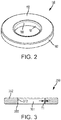
FIG. 2 illustrates a perspective view of the non-metallic orifice plate having the wear-resistant inner diameter surface, in accordance with various embodiments; -
FIG. 3 illustrates a section view of a non-metallic orifice plate having a wear-resistant coating defining a wear-resistant inner diameter surface, in accordance with various embodiments; -
FIG. 4A illustrates a perspective view of a non-metallic orifice plate having a wear-resistant insert defining a wear-resistant inner diameter surface, in accordance with various embodiments; -
FIG. 4B illustrates a section view of the non-metallic orifice plate having the wear-resistant insert defining the wear-resistant inner diameter surface ofFIG. 4A , in accordance with various embodiments; and -
FIG. 5 illustrates a method for manufacturing a non-metallic orifice plate, in accordance with various embodiments. - The subject matter of the present disclosure is particularly pointed out and distinctly claimed in the concluding portion of the specification. A more complete understanding of the present disclosure, however, may best be obtained by referring to the detailed description and claims when considered in connection with the drawing figures, wherein like numerals denote like elements.
- The detailed description of exemplary embodiments herein makes reference to the accompanying drawings, which show exemplary embodiments by way of illustration. While these exemplary embodiments are described in sufficient detail to enable those skilled in the art to practice the disclosure, it should be understood that other embodiments may be realized and that logical changes and adaptations in design and construction may be made in accordance with this disclosure and the teachings herein without departing from the scope of the invention as defined by the claims. Thus, the detailed description herein is presented for purposes of illustration only and not of limitation.
- As disclosed herein, a 100% non-metallic orifice plate may comprise a wear-resistant inner diameter surface, an outer diameter surface, a first side surface extending between the inner diameter surface and the outer diameter surface, and a second side surface extending between the inner diameter surface and the outer diameter surface, the second side surface disposed opposite the non-metallic orifice plate from the first side surface. The disclosed non-metallic orifice plate may provide weight-savings, while maintaining wear resistance at the inner diameter surface.
- With reference to
FIG. 1A , a section view of ashock strut 100 in a fully extended position is illustrated, in accordance with various embodiments.Shock strut 100 may be configured to absorb and dampen forces transmitted between a vehicle and the ground.Shock strut 100 may comprise astrut piston 112 and astrut cylinder 113.Strut cylinder 113 may be configured to receivestrut piston 112 in a manner that allows the two components to telescope together and absorb and dampen forces transmitted between a first end 101 (also referred to herein as a proximal end) and a second end 102 (also referred to herein as a distal end) ofshock strut 100. In various embodiments, a fluid, such as a hydraulic fluid, and oil, and/or a gas is located withinstrut cylinder 113.Strut cylinder 113 andstrut piston 112 may, for example, be configured to seal such that liquid contained withinstrut cylinder 113 is prevented from leaking asstrut piston 112 translates relative tostrut cylinder 113. Further,strut cylinder 113 may be configured to contain a gas such as nitrogen gas or air.Shock strut 100 may comprise aproximal end 101 and adistal end 102, wherein thedistal end 102 is opposite theproximal end 101, thedistal end 102 being the end of the shock strut closest to a wheel or wheel assembly of a vehicle. A gas chamber may be positioned above an oil chamber (referred to as an "air-over-oil" arrangement) or vice versa, where the term "above" in this context means in the direction of theproximal end 101 of theshock strut 100. Similarly,strut cylinder 113 andstrut piston 112 may be sealed such that gas is prevented from leaking asstrut piston 112 moves relative to strutcylinder 113. As such,shock strut 100 may comprise a pressurized environment withinstrut cylinder 113. - In various embodiments, the
strut cylinder 113 may comprise a hollow circular tube having various components disposed within.Strut cylinder 113 may comprise astrut chamber 118.Strut cylinder 113 may comprise anorifice support tube 140.Orifice support tube 140 may comprise a hollow tube having a plurality of orifices through which oil or gas may travel. In this regard,orifice support tube 140 may comprise atube channel 142 in fluid communication withstrut chamber 118. In thisregard strut chamber 118 may comprisetube channel 142 defined byorifice support tube 140. Various fluids may be disposed instrut chamber 118. Air may be disposed withinstrut chamber 118. Oil may be disposed withinstrut chamber 118, whether alone or in combination with a gas such as air or nitrogen gas. - In various embodiments,
strut piston 112 may comprise a hollow circular tube. At least a portion ofstrut piston 112 may be received byopen end 115 ofstrut cylinder 113.Strut piston 112 may comprise ametering pin 110.Metering pin 110 may move withstrut piston 112 with respect to strutcylinder 113.Metering pin 110 may be received inorifice support tube 140.Strut piston 112 may be reciprocally received within thestrut cylinder 113. In various embodiments,strut piston 112 may be reciprocally received withinstrut cylinder 113 in a concentric relationship with and between thestrut cylinder 113 andorifice support tube 140. In various embodiments, one or more bearings may be disposed betweenstrut cylinder 113 andstrut piston 112 against which thestrut piston 112 slides. - In various embodiments,
metering pin 110 may comprise a first end 131 (also referred to herein as a proximal end) and a second end 132 (also referred to herein as a distal end).Second end 132 may be coupled to strutpiston 112.First end 131 may be received intoorifice support tube 140. In various embodiments, thestrut cylinder 113 may comprise a non-metallic orifice plate 150 (also referred to herein as an orifice plate).Metering pin 110 may be received byorifice plate 150.Metering pin 110 may slide against an inner diameter (ID) surface oforifice plate 150. In this regard,metering pin 110 may extend throughorifice plate 150. - With reference to
FIG. 1B , an enlarged view oforifice plate 150 installed inshock strut 100 is illustrated, in accordance with various embodiments. In various embodiments,orifice plate 150 may be coupled toorifice support tube 140.Orifice plate 150 may be disposed inorifice support tube 140. The outer portion (i.e., at outer diameter (OD) surface 162) oforifice plate 150 may be coupled toorifice support tube 140. A threadedfastener 144 may be coupled to theopen end 141 oforifice support tube 140.Orifice plate 150 may float between threadedfastener 144 andorifice support tube 140. -
Orifice plate 150 may be comprised of a non-metallic material, such as a thermoplastic or a thermoset carbon fiber reinforced composite, for example.Orifice plate 150 may comprise an inner diameter (ID)surface 161 and an outer diameter (OD)surface 162.Orifice plate 150 may comprise awear surface 159.Wear surface 159 may define theID surface 161 oforifice plate 150.Wear surface 159 may provide a wear resilient surface against whichmetering pin 110 may slide. In this manner,orifice plate 150 may provide weight-savings while maintaining wear resistance atID surface 161. -
Orifice plate 150 may comprise afirst side surface 164 extending between theinner diameter surface 161 and theouter diameter surface 162.Orifice plate 150 may comprise asecond side surface 165 extending between theinner diameter surface 161 and theouter diameter surface 162. Thesecond side surface 165 is disposed opposite theorifice plate 150 from thefirst side surface 164. - In various embodiments,
metering pin 110 may be hollow. In various embodiments,metering pin 110 may comprise a plurality ofchannels 111 extending axially along the outer surface ofmetering pin 110 whereby a flow of a fluid betweenstrut piston 112 and strutcylinder 113 is metered, with momentary reference toFIG. 1A . Plurality ofchannels 111 may extend parallel withcenterline axis 190 ofmetering pin 110. In this regard, a fluid may flow from withinstrut piston 112 to strutchamber 118, via plurality ofchannels 111, in response toshock strut 100 moving towards a compressed position. Inversely, the fluid may flow from withinstrut chamber 118 to strut piston, via plurality ofchannels 111, in response toshock strut 100 moving towards an extended position. The size of eachchannel 111 may vary along the length ofmetering pin 110 such that the flow of the fluid betweenstrut chamber 118 andstrut piston 112 is metered dependent upon the position ofstrut piston 112 with respect to strutcylinder 113. For example, the depth of eachchannel 111 may be greater atfirst end 131 and may decrease in depth along the length ofmetering pin 110 towardssecond end 132. In this manner,metering pin 110 andorifice plate 150 may work together to meter a flow of fluid traveling betweenmetering pin 110 andorifice plate 150, throughchannels 111, withinshock strut 100. - With reference to
FIG. 2 , an isometric view oforifice plate 150 is illustrated, in accordance with various embodiments.Orifice plate 150 may comprise abody portion 152 comprising an annular geometry. In various embodiments,orifice plate 150 may comprise a wear-resistant material, such as polytetrafluoroethylene (PTFE) or a metal such as an electroless nickel plating, a bronze-based coating, a copper-based coating, or the like. In this regard, theID surface 161 may be wear-resistant to mitigate wear ofID surface 161 in response tometering pin 110 sliding againstID surface 161. - With reference to
FIG. 3 , a section view of anorifice plate 350 is illustrated, in accordance with various embodiments.Orifice plate 350 may be similar toorifice plate 150 ofFIG. 1 .Orifice plate 350 may comprise abody portion 352 and a wear-resistant coating 355 disposed on theID surface 372 ofbody portion 352. In this regard, wear-resistant coating 355 may define theID surface 361 oforifice plate 350. In various embodiments, wear-resistant coating 355 may be a thin-layer, wear-resistant coating comprising a thickness T1 of less than 0.1 millimeters (0.003937 inches). In various embodiments, the thickness T1 of wear-resistant coating 355 may be less than 0.01 millimeters (0.0003937 inches). Wear-resistant coating 355 may be applied toID surface 372 ofbody portion 352 using an electroplating process, an electroless plating process, a thermal spray process, physical vapor deposition (PVD), chemical vapor deposition (CVD), or any other suitable coating process. - In various embodiments,
body portion 352 is comprised of a lightweight thermoplastic material, such as polyethylene (PE), polypropylene, polyvinyl chloride (PVC), or the like. In various embodiments,body portion 352 is comprised of a thermoset carbon fiber reinforced composite. In this regard,body portion 352 may result in reduced weight of theoverall shock strut 100 as compared to orifice plates comprised of a metal material or other material which is heavier, per unit volume, than a thermoplastic material or a thermoset carbon fiber reinforced composite. In various embodiments, wear-resistant coating 355 may be comprised of a wear-resistant material, such as polytetrafluoroethylene, or a metal, for example. In this manner,orifice plate 350 may provide weight-savings while maintaining wear resistance atID surface 361. - With reference to
FIG. 4A , a section view of anorifice plate 450 is illustrated, in accordance with variousembodiments Orifice plate 450 may be similar toorifice plate 150 ofFIG. 1 .Orifice plate 450 may comprise abody portion 452 and a wear-resistant insert 455 coupled to theID surface 472 ofbody portion 452. In this regard, wear-resistant insert 455 may define theID surface 461 oforifice plate 450. In various embodiments,body portion 452 is comprised of a lightweight thermoplastic material, such as polyethylene (PE), polypropylene, polyvinyl chloride (PVC), or the like. In various embodiments,body portion 452 is comprised of a thermoset carbon fiber reinforced composite. In this regard,body portion 452 may result in reduced weight of theoverall shock strut 100 as compared to orifice plates comprised of a metal material or other material which is heavier, per unit volume, than a thermoplastic material or a thermoset carbon fiber reinforced composite. In various embodiments, wear-resistant insert 455 may be comprised of a wear-resistant material, such as polytetrafluoroethylene for example. In this manner,orifice plate 450 may provide weight-savings while maintaining wear resistance atID surface 461. - In various embodiments, wear-
resistant insert 455 comprises anID surface 461 and anOD surface 471. TheOD surface 471 may mate againstID surface 472 ofbody portion 452. In various embodiments,OD surface 471 of wear-resistant insert 455 is coupled toID surface 472 via a friction welding process. Stated differently, wear-resistant insert 455 may be friction welded tobody portion 452. In various embodiments,OD surface 471 of wear-resistant insert 455 is coupled toID surface 472 via an adhesive. Stated differently, wear-resistant insert 455 may be adhered tobody portion 452. - With reference to
FIG. 5 , a flow chart providing amethod 500 for manufacturing an orifice plate is illustrated, in accordance with various embodiments.Method 500 include forming a body portion of an orifice plate comprising a first material (step 510).Method 500 includes forming a wear-resistant inner diameter surface comprising a second material (step 520). Step 520 may be performed subsequent to step 510. - With combined reference to
FIG. 3 ,FIG. 4A, and FIG. 4B, and FIG. 5 , step 510 may include formingbody portion 352. Step 510 may include formingbody portion 452.Body portion 352 andbody portion 452 may be formed using any suitable process including additive manufacturing methods, subtractive manufacturing methods, a molding process, or any combination thereof.Body portion 352 and/orbody portion 452 may comprise a first material such as a thermoset carbon fiber reinforced composite or a thermoplastic material, including a polyethylene (PE), a polypropylene, a polyvinyl chloride (PVC), or the like - Step 520 may include applying wear-
resistant coating 355 onID surface 372 ofbody portion 352 to form wear-resistant ID surface 361. Wear-resistant coating 355 may be formed using any suitable process including electroplating, electroless plating, thermal spraying, physical vapor deposition (PVD), chemical vapor deposition (CVD), or any other suitable coating process. Step 520 may include coupling wear-resistant insert 455 tobody portion 452 to form wear-resistant ID surface 461. The outer diameter of wear-resistant insert 455 may be substantially equal to the inner diameter ofbody portion 452. Wear-resistant insert 455 may be coupled tobody portion 452 using any suitable process including friction welding, using adhesive, or the like. Wear-resistant coating 355 and/or wear-resistant insert 455 may comprise a second material, different from the first material. The second material may be a wear-resistant material such as a polytetrafluoroethylene or the like. - Benefits, other advantages, and solutions to problems have been described herein with regard to specific embodiments. Furthermore, the connecting lines shown in the various figures contained herein are intended to represent exemplary functional relationships and/or physical couplings between the various elements. It should be noted that many alternative or additional functional relationships or physical connections may be present in a practical system. However, the benefits, advantages, solutions to problems, and any elements that may cause any benefit, advantage, or solution to occur or become more pronounced are not to be construed as critical, required, or essential features or elements of the disclosure.
- The scope of the disclosure is accordingly to be limited by nothing other than the appended claims, in which reference to an element in the singular is not intended to mean "one and only one" unless explicitly so stated, but rather "one or more." It is to be understood that unless specifically stated otherwise, references to "a," "an," and/or "the" may include one or more than one and that reference to an item in the singular may also include the item in the plural. All ranges and ratio limits disclosed herein may be combined.
- Moreover, where a phrase similar to "at least one of A, B, and C" is used in the claims, it is intended that the phrase be interpreted to mean that A alone may be present in an embodiment, B alone may be present in an embodiment, C alone may be present in an embodiment, or that any combination of the elements A, B and C may be present in a single embodiment; for example, A and B, A and C, B and C, or A and B and C.
- The steps recited in any of the method or process descriptions may be executed in any order and are not necessarily limited to the order presented. Furthermore, any reference to singular includes plural embodiments, and any reference to more than one component or step may include a singular embodiment or step. Elements and steps in the figures are illustrated for simplicity and clarity and have not necessarily been rendered according to any particular sequence. For example, steps that may be performed concurrently or in different order are illustrated in the figures to help to improve understanding of embodiments of the present disclosure.
- Any reference to attached, fixed, connected or the like may include permanent, removable, temporary, partial, full and/or any other possible attachment option. Additionally, any reference to without contact (or similar phrases) may also include reduced contact or minimal contact. Surface shading lines may be used throughout the figures to denote different parts or areas but not necessarily to denote the same or different materials. In some cases, reference coordinates may be specific to each figure.
- Systems, methods and apparatus are provided herein. In the detailed description herein, references to "one embodiment", "an embodiment", "various embodiments", etc., indicate that the embodiment described may include a particular feature, structure, or characteristic, but every embodiment may not necessarily include the particular feature, structure, or characteristic. Moreover, such phrases are not necessarily referring to the same embodiment. Further, when a particular feature, structure, or characteristic is described in connection with an embodiment, it is submitted that it is within the knowledge of one skilled in the art to affect such feature, structure, or characteristic in connection with other embodiments whether or not explicitly described. After reading the description, it will be apparent to one skilled in the relevant art(s) how to implement the disclosure in alternative embodiments.
Claims (14)
- A non-metallic orifice plate, comprising:a wear-resistant inner diameter surface (161);an outer diameter surface (162);a first side surface (164) extending between the wear-resistant inner diameter surface and the outer diameter surface; anda second side surface (165) extending between the wear-resistant inner diameter surface and the outer diameter surface, the second side surface disposed opposite the non-metallic orifice plate from the first side surface.
- The non-metallic orifice plate of claim 1, wherein the non-metallic orifice plate comprises a body portion (152) comprising a first material.
- The non-metallic orifice plate of claim 2, wherein the wear-resistant inner diameter surface comprises a second material.
- The non-metallic orifice plate of claim 3, wherein the first material comprises at least one of a thermoplastic and a thermoset carbon fiber reinforced composite.
- The non-metallic orifice plate of claim 4, wherein the second material comprises a polytetrafluoroethylene.
- The non-metallic orifice plate of claim 3, 4 or 5, further comprising a wear insert (455) disposed in the body portion of the non-metallic orifice plate.
- The non-metallic orifice plate of claim 6, wherein the wear insert defines the wear-resistant inner diameter surface.
- The non-metallic orifice plate of any of claims 3 to 7, further comprising a wear-resistant coating (355) comprising the second material disposed on the body portion and defining the wear-resistant inner diameter surface.
- A shock strut, comprising:a strut cylinder (113);a strut piston (112) operatively coupled to the strut cylinder;a non-metallic orifice plate (150); anda metering pin (110) extending through the non-metallic orifice plate.
- A method for manufacturing a non-metallic orifice plate, comprising:forming a body portion of the non-metallic orifice plate; andforming a wear-resistant inner diameter surface of the non-metallic orifice plate, wherein the body portion comprises a first material and the wear-resistant inner diameter surface comprises a second material.
- The method of claim 10, wherein the wear-resistant inner diameter surface is formed by applying a wear-resistant coating to an inner diameter surface of the body portion.
- The method of claim 10, wherein the wear-resistant inner diameter surface is formed by applying a wear-resistant coating to an inner diameter surface of the body portion.
- The method of claim 10, 11 or 12, wherein the first material comprises a polytetrafluoroethylene.
- The method of claim 13, wherein the second material comprises at least one of a thermoplastic or a thermoset carbon fiber reinforced composite.
Applications Claiming Priority (1)
| Application Number | Priority Date | Filing Date | Title |
|---|---|---|---|
| US16/276,246 US11192642B2 (en) | 2019-02-14 | 2019-02-14 | Non-metallic orifice plate |
Publications (2)
| Publication Number | Publication Date |
|---|---|
| EP3696440A1 true EP3696440A1 (en) | 2020-08-19 |
| EP3696440B1 EP3696440B1 (en) | 2024-09-18 |
Family
ID=68840973
Family Applications (1)
| Application Number | Title | Priority Date | Filing Date |
|---|---|---|---|
| EP19214552.2A Active EP3696440B1 (en) | 2019-02-14 | 2019-12-09 | Shock strut with a non-metallic orifice plate |
Country Status (2)
| Country | Link |
|---|---|
| US (1) | US11192642B2 (en) |
| EP (1) | EP3696440B1 (en) |
Citations (3)
| Publication number | Priority date | Publication date | Assignee | Title |
|---|---|---|---|---|
| US3451510A (en) * | 1968-01-22 | 1969-06-24 | Pneumo Dynamics Corp | Metering shock absorber with snubbing means and snub release means |
| EP0074705A1 (en) * | 1981-08-25 | 1983-03-23 | Fike Metal Products Corporation | Shear type pressure relief device for hydraulic energy absorption unit |
| US20070164151A1 (en) * | 2006-01-13 | 2007-07-19 | Luce William E | Aircraft shock strut and improved bearings therefor |
Family Cites Families (25)
| Publication number | Priority date | Publication date | Assignee | Title |
|---|---|---|---|---|
| US2719612A (en) * | 1946-06-14 | 1955-10-04 | Bourcier Christian Marie Louis | Shock absorbers |
| US2838300A (en) * | 1957-04-17 | 1958-06-10 | Erie Resistor Corp | Dashpot |
| US3053593A (en) * | 1959-05-27 | 1962-09-11 | Chicago Rawhide Mfg Co | Polytetrafluoroethylene bushings and washers and method of forming same |
| US4074011A (en) * | 1974-04-25 | 1978-02-14 | Nippon Steel Corporation | Topcoated phosphated bolts, nuts and washers |
| US4163970A (en) * | 1975-05-23 | 1979-08-07 | Allinquant F M | Pneumatic springs and other telescopic systems |
| US4067184A (en) * | 1976-10-12 | 1978-01-10 | Coats & Clark, Inc. | Noise reducing spindle washers |
| US4214507A (en) * | 1977-08-24 | 1980-07-29 | Vries Donald S Jr De | One-piece plastic piston |
| US4628579A (en) * | 1979-09-19 | 1986-12-16 | Tayco Developments, Inc. | Method of fabricating a liquid spring shock absorber with integral plastic body and seal |
| US4426109A (en) * | 1981-07-20 | 1984-01-17 | Fike Metal Products Corporation | Shear type pressure relief device for hydraulic energy absorption unit |
| US4984938A (en) * | 1988-08-25 | 1991-01-15 | H&S Machine & Supply Company, Inc. | Coated washer for an anchor bolt system |
| JPH0810702Y2 (en) * | 1990-11-06 | 1996-03-29 | 旭電化工業株式会社 | Washer with water-swellable rubber |
| JP2917992B1 (en) * | 1998-04-10 | 1999-07-12 | 日本電気株式会社 | Polishing equipment |
| US6186486B1 (en) * | 1999-07-30 | 2001-02-13 | Delphi Technologies, Inc. | Jounce bumper plate |
| DE10108246A1 (en) * | 2001-02-21 | 2002-09-19 | Gkn Sinter Metals Gmbh | Pistons with support webs for a piston-cylinder arrangement, in particular shock absorber pistons |
| US6758939B2 (en) * | 2001-08-31 | 2004-07-06 | Speedfam-Ipec Corporation | Laminated wear ring |
| US6610165B2 (en) * | 2001-09-17 | 2003-08-26 | Illinois Tool Works Inc. | Method for coating an orifice plate |
| JP2004183862A (en) * | 2002-12-06 | 2004-07-02 | Daido Metal Co Ltd | Hydraulic buffer |
| US6883649B2 (en) * | 2003-03-21 | 2005-04-26 | Delphi Technologies, Inc. | Closing system for a magneto-rheological damper |
| US20100225110A1 (en) * | 2009-03-06 | 2010-09-09 | Dean Christie | Sealing washer with multiple sealing rings |
| EP3019641A4 (en) | 2013-07-09 | 2017-07-19 | United Technologies Corporation | Plated polymer aviation components |
| EP3019766B1 (en) * | 2013-07-12 | 2025-11-05 | Astemo, Ltd. | Hydraulic shock absorber and cover member |
| US9261159B2 (en) * | 2013-12-11 | 2016-02-16 | Zf Friedrichshafen Ag | Fire protection for mono-tube damper |
| US9403592B2 (en) | 2014-06-02 | 2016-08-02 | Goodrich Corporation | Two-stage secondary piston for landing gear |
| KR102391002B1 (en) * | 2017-09-11 | 2022-04-27 | 현대자동차주식회사 | Coating material and washer for drive shaft using thereof |
| US10587107B2 (en) * | 2017-09-25 | 2020-03-10 | The Boeing Company | Dual protection inner seal washer for electromagnetic effects (EME) fasteners |
-
2019
- 2019-02-14 US US16/276,246 patent/US11192642B2/en active Active
- 2019-12-09 EP EP19214552.2A patent/EP3696440B1/en active Active
Patent Citations (3)
| Publication number | Priority date | Publication date | Assignee | Title |
|---|---|---|---|---|
| US3451510A (en) * | 1968-01-22 | 1969-06-24 | Pneumo Dynamics Corp | Metering shock absorber with snubbing means and snub release means |
| EP0074705A1 (en) * | 1981-08-25 | 1983-03-23 | Fike Metal Products Corporation | Shear type pressure relief device for hydraulic energy absorption unit |
| US20070164151A1 (en) * | 2006-01-13 | 2007-07-19 | Luce William E | Aircraft shock strut and improved bearings therefor |
Also Published As
| Publication number | Publication date |
|---|---|
| EP3696440B1 (en) | 2024-09-18 |
| US20200262547A1 (en) | 2020-08-20 |
| US11192642B2 (en) | 2021-12-07 |
Similar Documents
| Publication | Publication Date | Title |
|---|---|---|
| EP2210811B1 (en) | Aircraft shock strut having fixed upper bearing | |
| EP2505499B1 (en) | Landing gear system | |
| EP3345828B1 (en) | Two stage strut allowing low initial compression load | |
| EP2848523B1 (en) | Aircraft shock strut and rebound damping ring | |
| US11192641B2 (en) | Aircraft and landing gear provided with at least one pair of shock absorbers, and a method performed by said landing gear | |
| DE102011087597A1 (en) | Telescopic vibration damper for motor car wheel suspension, has outer tube whose upper end is connected with seal guide element through fastening device for passage of piston rod | |
| EP3696440B1 (en) | Shock strut with a non-metallic orifice plate | |
| US12372133B2 (en) | Shock absorber | |
| US12552522B2 (en) | Shock strut variable-area metering unit | |
| US9061759B2 (en) | Cam-operated bi-directional shock absorber damper | |
| US20240140597A1 (en) | Landing gear main fitting with integral shock absorber | |
| EP3690276B1 (en) | Additively manufactured thermoplastic metering pin with slots for retention hardware | |
| US11391340B2 (en) | Non-metallic orifice plate with metallic wear insert | |
| CA3065268C (en) | Aircraft landing gear shock absorber assembly | |
| EP3696431B1 (en) | Composite shock strut cylinder with integral metallic lower bearing carrier and sleeve | |
| EP3505788B1 (en) | Shock strut percolation | |
| DE102013204846A1 (en) | Lightweight telescopic shock absorber | |
| EP3486521B1 (en) | Shock strut with integral shrink piston actuator |
Legal Events
| Date | Code | Title | Description |
|---|---|---|---|
| PUAI | Public reference made under article 153(3) epc to a published international application that has entered the european phase |
Free format text: ORIGINAL CODE: 0009012 |
|
| STAA | Information on the status of an ep patent application or granted ep patent |
Free format text: STATUS: THE APPLICATION HAS BEEN PUBLISHED |
|
| AK | Designated contracting states |
Kind code of ref document: A1 Designated state(s): AL AT BE BG CH CY CZ DE DK EE ES FI FR GB GR HR HU IE IS IT LI LT LU LV MC MK MT NL NO PL PT RO RS SE SI SK SM TR |
|
| AX | Request for extension of the european patent |
Extension state: BA ME |
|
| STAA | Information on the status of an ep patent application or granted ep patent |
Free format text: STATUS: REQUEST FOR EXAMINATION WAS MADE |
|
| 17P | Request for examination filed |
Effective date: 20210219 |
|
| RBV | Designated contracting states (corrected) |
Designated state(s): AL AT BE BG CH CY CZ DE DK EE ES FI FR GB GR HR HU IE IS IT LI LT LU LV MC MK MT NL NO PL PT RO RS SE SI SK SM TR |
|
| STAA | Information on the status of an ep patent application or granted ep patent |
Free format text: STATUS: EXAMINATION IS IN PROGRESS |
|
| 17Q | First examination report despatched |
Effective date: 20230713 |
|
| P01 | Opt-out of the competence of the unified patent court (upc) registered |
Effective date: 20230922 |
|
| REG | Reference to a national code |
Ref country code: DE Ref country code: DE Ref legal event code: R079 Ref document number: 602019059020 Country of ref document: DE Free format text: PREVIOUS MAIN CLASS: F16F0009342000 Ipc: F16C0017040000 |
|
| RIC1 | Information provided on ipc code assigned before grant |
Ipc: F16C 33/20 20060101ALI20240227BHEP Ipc: F16C 17/04 20060101AFI20240227BHEP |
|
| GRAP | Despatch of communication of intention to grant a patent |
Free format text: ORIGINAL CODE: EPIDOSNIGR1 |
|
| STAA | Information on the status of an ep patent application or granted ep patent |
Free format text: STATUS: GRANT OF PATENT IS INTENDED |
|
| INTG | Intention to grant announced |
Effective date: 20240411 |
|
| GRAS | Grant fee paid |
Free format text: ORIGINAL CODE: EPIDOSNIGR3 |
|
| GRAA | (expected) grant |
Free format text: ORIGINAL CODE: 0009210 |
|
| STAA | Information on the status of an ep patent application or granted ep patent |
Free format text: STATUS: THE PATENT HAS BEEN GRANTED |
|
| AK | Designated contracting states |
Kind code of ref document: B1 Designated state(s): AL AT BE BG CH CY CZ DE DK EE ES FI FR GB GR HR HU IE IS IT LI LT LU LV MC MK MT NL NO PL PT RO RS SE SI SK SM TR |
|
| REG | Reference to a national code |
Ref country code: GB Ref legal event code: FG4D |
|
| REG | Reference to a national code |
Ref country code: CH Ref legal event code: EP |
|
| REG | Reference to a national code |
Ref country code: IE Ref legal event code: FG4D |
|
| REG | Reference to a national code |
Ref country code: DE Ref legal event code: R096 Ref document number: 602019059020 Country of ref document: DE |
|
| REG | Reference to a national code |
Ref country code: LT Ref legal event code: MG9D |
|
| PG25 | Lapsed in a contracting state [announced via postgrant information from national office to epo] |
Ref country code: NO Free format text: LAPSE BECAUSE OF FAILURE TO SUBMIT A TRANSLATION OF THE DESCRIPTION OR TO PAY THE FEE WITHIN THE PRESCRIBED TIME-LIMIT Effective date: 20241218 |
|
| PG25 | Lapsed in a contracting state [announced via postgrant information from national office to epo] |
Ref country code: GR Free format text: LAPSE BECAUSE OF FAILURE TO SUBMIT A TRANSLATION OF THE DESCRIPTION OR TO PAY THE FEE WITHIN THE PRESCRIBED TIME-LIMIT Effective date: 20241219 Ref country code: FI Free format text: LAPSE BECAUSE OF FAILURE TO SUBMIT A TRANSLATION OF THE DESCRIPTION OR TO PAY THE FEE WITHIN THE PRESCRIBED TIME-LIMIT Effective date: 20240918 |
|
| PG25 | Lapsed in a contracting state [announced via postgrant information from national office to epo] |
Ref country code: BG Free format text: LAPSE BECAUSE OF FAILURE TO SUBMIT A TRANSLATION OF THE DESCRIPTION OR TO PAY THE FEE WITHIN THE PRESCRIBED TIME-LIMIT Effective date: 20240918 |
|
| PG25 | Lapsed in a contracting state [announced via postgrant information from national office to epo] |
Ref country code: LV Free format text: LAPSE BECAUSE OF FAILURE TO SUBMIT A TRANSLATION OF THE DESCRIPTION OR TO PAY THE FEE WITHIN THE PRESCRIBED TIME-LIMIT Effective date: 20240918 |
|
| PG25 | Lapsed in a contracting state [announced via postgrant information from national office to epo] |
Ref country code: HR Free format text: LAPSE BECAUSE OF FAILURE TO SUBMIT A TRANSLATION OF THE DESCRIPTION OR TO PAY THE FEE WITHIN THE PRESCRIBED TIME-LIMIT Effective date: 20240918 |
|
| REG | Reference to a national code |
Ref country code: NL Ref legal event code: MP Effective date: 20240918 |
|
| PG25 | Lapsed in a contracting state [announced via postgrant information from national office to epo] |
Ref country code: RS Free format text: LAPSE BECAUSE OF FAILURE TO SUBMIT A TRANSLATION OF THE DESCRIPTION OR TO PAY THE FEE WITHIN THE PRESCRIBED TIME-LIMIT Effective date: 20241218 |
|
| PG25 | Lapsed in a contracting state [announced via postgrant information from national office to epo] |
Ref country code: RS Free format text: LAPSE BECAUSE OF FAILURE TO SUBMIT A TRANSLATION OF THE DESCRIPTION OR TO PAY THE FEE WITHIN THE PRESCRIBED TIME-LIMIT Effective date: 20241218 Ref country code: NO Free format text: LAPSE BECAUSE OF FAILURE TO SUBMIT A TRANSLATION OF THE DESCRIPTION OR TO PAY THE FEE WITHIN THE PRESCRIBED TIME-LIMIT Effective date: 20241218 Ref country code: LV Free format text: LAPSE BECAUSE OF FAILURE TO SUBMIT A TRANSLATION OF THE DESCRIPTION OR TO PAY THE FEE WITHIN THE PRESCRIBED TIME-LIMIT Effective date: 20240918 Ref country code: HR Free format text: LAPSE BECAUSE OF FAILURE TO SUBMIT A TRANSLATION OF THE DESCRIPTION OR TO PAY THE FEE WITHIN THE PRESCRIBED TIME-LIMIT Effective date: 20240918 Ref country code: GR Free format text: LAPSE BECAUSE OF FAILURE TO SUBMIT A TRANSLATION OF THE DESCRIPTION OR TO PAY THE FEE WITHIN THE PRESCRIBED TIME-LIMIT Effective date: 20241219 Ref country code: FI Free format text: LAPSE BECAUSE OF FAILURE TO SUBMIT A TRANSLATION OF THE DESCRIPTION OR TO PAY THE FEE WITHIN THE PRESCRIBED TIME-LIMIT Effective date: 20240918 Ref country code: BG Free format text: LAPSE BECAUSE OF FAILURE TO SUBMIT A TRANSLATION OF THE DESCRIPTION OR TO PAY THE FEE WITHIN THE PRESCRIBED TIME-LIMIT Effective date: 20240918 |
|
| REG | Reference to a national code |
Ref country code: AT Ref legal event code: MK05 Ref document number: 1724917 Country of ref document: AT Kind code of ref document: T Effective date: 20240918 |
|
| PG25 | Lapsed in a contracting state [announced via postgrant information from national office to epo] |
Ref country code: NL Free format text: LAPSE BECAUSE OF FAILURE TO SUBMIT A TRANSLATION OF THE DESCRIPTION OR TO PAY THE FEE WITHIN THE PRESCRIBED TIME-LIMIT Effective date: 20240918 |
|
| PG25 | Lapsed in a contracting state [announced via postgrant information from national office to epo] |
Ref country code: PT Free format text: LAPSE BECAUSE OF FAILURE TO SUBMIT A TRANSLATION OF THE DESCRIPTION OR TO PAY THE FEE WITHIN THE PRESCRIBED TIME-LIMIT Effective date: 20250120 Ref country code: IS Free format text: LAPSE BECAUSE OF FAILURE TO SUBMIT A TRANSLATION OF THE DESCRIPTION OR TO PAY THE FEE WITHIN THE PRESCRIBED TIME-LIMIT Effective date: 20250118 |
|
| PG25 | Lapsed in a contracting state [announced via postgrant information from national office to epo] |
Ref country code: SM Free format text: LAPSE BECAUSE OF FAILURE TO SUBMIT A TRANSLATION OF THE DESCRIPTION OR TO PAY THE FEE WITHIN THE PRESCRIBED TIME-LIMIT Effective date: 20240918 Ref country code: RO Free format text: LAPSE BECAUSE OF FAILURE TO SUBMIT A TRANSLATION OF THE DESCRIPTION OR TO PAY THE FEE WITHIN THE PRESCRIBED TIME-LIMIT Effective date: 20240918 |
|
| PG25 | Lapsed in a contracting state [announced via postgrant information from national office to epo] |
Ref country code: ES Free format text: LAPSE BECAUSE OF FAILURE TO SUBMIT A TRANSLATION OF THE DESCRIPTION OR TO PAY THE FEE WITHIN THE PRESCRIBED TIME-LIMIT Effective date: 20240918 |
|
| PG25 | Lapsed in a contracting state [announced via postgrant information from national office to epo] |
Ref country code: AT Free format text: LAPSE BECAUSE OF FAILURE TO SUBMIT A TRANSLATION OF THE DESCRIPTION OR TO PAY THE FEE WITHIN THE PRESCRIBED TIME-LIMIT Effective date: 20240918 Ref country code: EE Free format text: LAPSE BECAUSE OF FAILURE TO SUBMIT A TRANSLATION OF THE DESCRIPTION OR TO PAY THE FEE WITHIN THE PRESCRIBED TIME-LIMIT Effective date: 20240918 |
|
| PG25 | Lapsed in a contracting state [announced via postgrant information from national office to epo] |
Ref country code: CZ Free format text: LAPSE BECAUSE OF FAILURE TO SUBMIT A TRANSLATION OF THE DESCRIPTION OR TO PAY THE FEE WITHIN THE PRESCRIBED TIME-LIMIT Effective date: 20240918 Ref country code: PL Free format text: LAPSE BECAUSE OF FAILURE TO SUBMIT A TRANSLATION OF THE DESCRIPTION OR TO PAY THE FEE WITHIN THE PRESCRIBED TIME-LIMIT Effective date: 20240918 |
|
| PG25 | Lapsed in a contracting state [announced via postgrant information from national office to epo] |
Ref country code: IT Free format text: LAPSE BECAUSE OF FAILURE TO SUBMIT A TRANSLATION OF THE DESCRIPTION OR TO PAY THE FEE WITHIN THE PRESCRIBED TIME-LIMIT Effective date: 20240918 Ref country code: SK Free format text: LAPSE BECAUSE OF FAILURE TO SUBMIT A TRANSLATION OF THE DESCRIPTION OR TO PAY THE FEE WITHIN THE PRESCRIBED TIME-LIMIT Effective date: 20240918 |
|
| REG | Reference to a national code |
Ref country code: DE Ref legal event code: R097 Ref document number: 602019059020 Country of ref document: DE |
|
| PG25 | Lapsed in a contracting state [announced via postgrant information from national office to epo] |
Ref country code: MC Free format text: LAPSE BECAUSE OF FAILURE TO SUBMIT A TRANSLATION OF THE DESCRIPTION OR TO PAY THE FEE WITHIN THE PRESCRIBED TIME-LIMIT Effective date: 20240918 |
|
| PG25 | Lapsed in a contracting state [announced via postgrant information from national office to epo] |
Ref country code: DK Free format text: LAPSE BECAUSE OF FAILURE TO SUBMIT A TRANSLATION OF THE DESCRIPTION OR TO PAY THE FEE WITHIN THE PRESCRIBED TIME-LIMIT Effective date: 20240918 |
|
| PLBE | No opposition filed within time limit |
Free format text: ORIGINAL CODE: 0009261 |
|
| STAA | Information on the status of an ep patent application or granted ep patent |
Free format text: STATUS: NO OPPOSITION FILED WITHIN TIME LIMIT |
|
| REG | Reference to a national code |
Ref country code: CH Ref legal event code: PL |
|
| PG25 | Lapsed in a contracting state [announced via postgrant information from national office to epo] |
Ref country code: LU Free format text: LAPSE BECAUSE OF NON-PAYMENT OF DUE FEES Effective date: 20241209 |
|
| 26N | No opposition filed |
Effective date: 20250619 |
|
| GBPC | Gb: european patent ceased through non-payment of renewal fee |
Effective date: 20241218 |
|
| PG25 | Lapsed in a contracting state [announced via postgrant information from national office to epo] |
Ref country code: SE Free format text: LAPSE BECAUSE OF FAILURE TO SUBMIT A TRANSLATION OF THE DESCRIPTION OR TO PAY THE FEE WITHIN THE PRESCRIBED TIME-LIMIT Effective date: 20240918 |
|
| REG | Reference to a national code |
Ref country code: BE Ref legal event code: MM Effective date: 20241231 |
|
| PG25 | Lapsed in a contracting state [announced via postgrant information from national office to epo] |
Ref country code: GB Free format text: LAPSE BECAUSE OF NON-PAYMENT OF DUE FEES Effective date: 20241218 Ref country code: BE Free format text: LAPSE BECAUSE OF NON-PAYMENT OF DUE FEES Effective date: 20241231 |
|
| PG25 | Lapsed in a contracting state [announced via postgrant information from national office to epo] |
Ref country code: CH Free format text: LAPSE BECAUSE OF NON-PAYMENT OF DUE FEES Effective date: 20241231 |
|
| PG25 | Lapsed in a contracting state [announced via postgrant information from national office to epo] |
Ref country code: IE Free format text: LAPSE BECAUSE OF NON-PAYMENT OF DUE FEES Effective date: 20241209 |
|
| PGFP | Annual fee paid to national office [announced via postgrant information from national office to epo] |
Ref country code: DE Payment date: 20251126 Year of fee payment: 7 |
|
| PGFP | Annual fee paid to national office [announced via postgrant information from national office to epo] |
Ref country code: FR Payment date: 20251119 Year of fee payment: 7 |