EP3696424A1 - Dual fluid rotating shaft - Google Patents
Dual fluid rotating shaft Download PDFInfo
- Publication number
- EP3696424A1 EP3696424A1 EP19211136.7A EP19211136A EP3696424A1 EP 3696424 A1 EP3696424 A1 EP 3696424A1 EP 19211136 A EP19211136 A EP 19211136A EP 3696424 A1 EP3696424 A1 EP 3696424A1
- Authority
- EP
- European Patent Office
- Prior art keywords
- shaft body
- internal fluid
- fluid channel
- recited
- internal
- Prior art date
- Legal status (The legal status is an assumption and is not a legal conclusion. Google has not performed a legal analysis and makes no representation as to the accuracy of the status listed.)
- Granted
Links
Images

Classifications
-
- F—MECHANICAL ENGINEERING; LIGHTING; HEATING; WEAPONS; BLASTING
- F04—POSITIVE - DISPLACEMENT MACHINES FOR LIQUIDS; PUMPS FOR LIQUIDS OR ELASTIC FLUIDS
- F04D—NON-POSITIVE-DISPLACEMENT PUMPS
- F04D29/00—Details, component parts, or accessories
- F04D29/58—Cooling; Heating; Diminishing heat transfer
- F04D29/582—Cooling; Heating; Diminishing heat transfer specially adapted for elastic fluid pumps
- F04D29/584—Cooling; Heating; Diminishing heat transfer specially adapted for elastic fluid pumps cooling or heating the machine
-
- H—ELECTRICITY
- H02—GENERATION; CONVERSION OR DISTRIBUTION OF ELECTRIC POWER
- H02K—DYNAMO-ELECTRIC MACHINES
- H02K9/00—Arrangements for cooling or ventilating
- H02K9/19—Arrangements for cooling or ventilating for machines with closed casing and closed-circuit cooling using a liquid cooling medium, e.g. oil
-
- F—MECHANICAL ENGINEERING; LIGHTING; HEATING; WEAPONS; BLASTING
- F04—POSITIVE - DISPLACEMENT MACHINES FOR LIQUIDS; PUMPS FOR LIQUIDS OR ELASTIC FLUIDS
- F04D—NON-POSITIVE-DISPLACEMENT PUMPS
- F04D29/00—Details, component parts, or accessories
- F04D29/05—Shafts or bearings, or assemblies thereof, specially adapted for elastic fluid pumps
- F04D29/053—Shafts
-
- F—MECHANICAL ENGINEERING; LIGHTING; HEATING; WEAPONS; BLASTING
- F04—POSITIVE - DISPLACEMENT MACHINES FOR LIQUIDS; PUMPS FOR LIQUIDS OR ELASTIC FLUIDS
- F04D—NON-POSITIVE-DISPLACEMENT PUMPS
- F04D29/00—Details, component parts, or accessories
- F04D29/06—Lubrication
- F04D29/063—Lubrication specially adapted for elastic fluid pumps
-
- F—MECHANICAL ENGINEERING; LIGHTING; HEATING; WEAPONS; BLASTING
- F04—POSITIVE - DISPLACEMENT MACHINES FOR LIQUIDS; PUMPS FOR LIQUIDS OR ELASTIC FLUIDS
- F04D—NON-POSITIVE-DISPLACEMENT PUMPS
- F04D29/00—Details, component parts, or accessories
- F04D29/58—Cooling; Heating; Diminishing heat transfer
- F04D29/5806—Cooling the drive system
-
- H—ELECTRICITY
- H02—GENERATION; CONVERSION OR DISTRIBUTION OF ELECTRIC POWER
- H02K—DYNAMO-ELECTRIC MACHINES
- H02K1/00—Details of the magnetic circuit
- H02K1/06—Details of the magnetic circuit characterised by the shape, form or construction
- H02K1/22—Rotating parts of the magnetic circuit
- H02K1/32—Rotating parts of the magnetic circuit with channels or ducts for flow of cooling medium
-
- H—ELECTRICITY
- H02—GENERATION; CONVERSION OR DISTRIBUTION OF ELECTRIC POWER
- H02K—DYNAMO-ELECTRIC MACHINES
- H02K9/00—Arrangements for cooling or ventilating
-
- F—MECHANICAL ENGINEERING; LIGHTING; HEATING; WEAPONS; BLASTING
- F01—MACHINES OR ENGINES IN GENERAL; ENGINE PLANTS IN GENERAL; STEAM ENGINES
- F01D—NON-POSITIVE DISPLACEMENT MACHINES OR ENGINES, e.g. STEAM TURBINES
- F01D25/00—Component parts, details, or accessories, not provided for in, or of interest apart from, other groups
- F01D25/08—Cooling; Heating; Heat-insulation
- F01D25/12—Cooling
-
- F—MECHANICAL ENGINEERING; LIGHTING; HEATING; WEAPONS; BLASTING
- F01—MACHINES OR ENGINES IN GENERAL; ENGINE PLANTS IN GENERAL; STEAM ENGINES
- F01D—NON-POSITIVE DISPLACEMENT MACHINES OR ENGINES, e.g. STEAM TURBINES
- F01D25/00—Component parts, details, or accessories, not provided for in, or of interest apart from, other groups
- F01D25/18—Lubricating arrangements
-
- F—MECHANICAL ENGINEERING; LIGHTING; HEATING; WEAPONS; BLASTING
- F05—INDEXING SCHEMES RELATING TO ENGINES OR PUMPS IN VARIOUS SUBCLASSES OF CLASSES F01-F04
- F05D—INDEXING SCHEME FOR ASPECTS RELATING TO NON-POSITIVE-DISPLACEMENT MACHINES OR ENGINES, GAS-TURBINES OR JET-PROPULSION PLANTS
- F05D2240/00—Components
- F05D2240/60—Shafts
- F05D2240/61—Hollow
-
- F—MECHANICAL ENGINEERING; LIGHTING; HEATING; WEAPONS; BLASTING
- F05—INDEXING SCHEMES RELATING TO ENGINES OR PUMPS IN VARIOUS SUBCLASSES OF CLASSES F01-F04
- F05D—INDEXING SCHEME FOR ASPECTS RELATING TO NON-POSITIVE-DISPLACEMENT MACHINES OR ENGINES, GAS-TURBINES OR JET-PROPULSION PLANTS
- F05D2260/00—Function
- F05D2260/20—Heat transfer, e.g. cooling
-
- F—MECHANICAL ENGINEERING; LIGHTING; HEATING; WEAPONS; BLASTING
- F16—ENGINEERING ELEMENTS AND UNITS; GENERAL MEASURES FOR PRODUCING AND MAINTAINING EFFECTIVE FUNCTIONING OF MACHINES OR INSTALLATIONS; THERMAL INSULATION IN GENERAL
- F16C—SHAFTS; FLEXIBLE SHAFTS; ELEMENTS OR CRANKSHAFT MECHANISMS; ROTARY BODIES OTHER THAN GEARING ELEMENTS; BEARINGS
- F16C2380/00—Electrical apparatus
- F16C2380/26—Dynamo-electric machines or combinations therewith, e.g. electro-motors and generators
-
- F—MECHANICAL ENGINEERING; LIGHTING; HEATING; WEAPONS; BLASTING
- F16—ENGINEERING ELEMENTS AND UNITS; GENERAL MEASURES FOR PRODUCING AND MAINTAINING EFFECTIVE FUNCTIONING OF MACHINES OR INSTALLATIONS; THERMAL INSULATION IN GENERAL
- F16C—SHAFTS; FLEXIBLE SHAFTS; ELEMENTS OR CRANKSHAFT MECHANISMS; ROTARY BODIES OTHER THAN GEARING ELEMENTS; BEARINGS
- F16C3/00—Shafts; Axles; Cranks; Eccentrics
- F16C3/02—Shafts; Axles
-
- H—ELECTRICITY
- H02—GENERATION; CONVERSION OR DISTRIBUTION OF ELECTRIC POWER
- H02K—DYNAMO-ELECTRIC MACHINES
- H02K7/00—Arrangements for handling mechanical energy structurally associated with dynamo-electric machines, e.g. structural association with mechanical driving motors or auxiliary dynamo-electric machines
- H02K7/08—Structural association with bearings
- H02K7/083—Structural association with bearings radially supporting the rotary shaft at both ends of the rotor
Definitions
- the present disclosure relates to rotary components, and more particularly to rotating shafts such as in electrical motors, generators and the like.
- the amount of heat created by an electrical machine such as a generator requires cooling.
- a coolant is required to dissipate heat.
- the bearings also require lubricant to ensure proper bearing function.
- Designers choose a coolant that can double as the lubricant or else choose a lubricant that can double as a coolant. This compromise limits designs.
- a system includes a shaft body defining a longitudinal axis.
- a first internal fluid channel extends axially within the shaft body and includes an inlet opening through the shaft body for fluid communication of external fluid into the first internal fluid channel and an outlet opening through the shaft body for fluid communication of fluid from the first internal fluid channel to an area external of the shaft body.
- a second internal fluid channel extends axially within the shaft body and includes an inlet opening through the shaft body for fluid communication of external fluid into the second internal fluid channel and an outlet opening through the shaft body for fluid communication of fluid from the second internal fluid channel to an area external of the shaft body.
- the first and second internal fluid channels are in fluid isolation from one another within the shaft body.
- the first internal fluid channel can be configured for coolant flow and the second internal fluid channel can be configured for lubricant flow.
- the inlet and outlet openings of the first internal fluid channel can extend in a lateral direction relative to the longitudinal axis.
- Each of the inlet and outlet openings of the second internal fluid channel can open in a radial direction, respectively, relative to the longitudinal axis.
- the first internal fluid channel can include two diametrically opposed sub-channels for balanced rotation of the shaft body.
- the second internal fluid channel can include two diametrically opposed sub-channels for balanced rotation of the shaft body.
- the second internal fluid channel can include at least one additional outlet.
- An electrical machine rotor can be mounted to the shaft body wherein seals sealing between the rotor and the shaft body maintain fluid isolation between the inlet openings and outlet openings of the first and second internal fluid channels.
- a support shaft can be included, wherein the shaft body is seated within the support shaft and wherein the support shaft supports the rotor.
- a stator can be included with the rotor and shaft body mounted to bearings for rotation relative to the stator.
- the outlet opening of the second internal fluid channel can be positioned to supply lubricant to the bearings.
- the outlet opening of the first internal fluid channel can be positioned to supply coolant to windings in at least one of the stator and the rotor.
- a method of operating an electrical machine includes issuing a coolant from a first internal fluid channel of a rotating shaft to a component in the electrical machine and issuing a lubricant different from the coolant from a second internal fluid channel of the rotating shaft.
- Issuing coolant and issuing a lubricant include keeping the coolant and lubricant in fluid isolation from each other within the rotating shaft.
- the component can be a heat generating component.
- the method can include issuing lubricant to a bearing of the electrical machine from the second internal fluid channel of the rotating shaft.
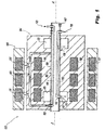
- Fig. 1 a partial view of an exemplary embodiment of a system in accordance with the disclosure is shown in Fig. 1 and is designated generally by reference character 100.
- FIGs. 2-7 Other embodiments of systems in accordance with the disclosure, or aspects thereof, are provided in Figs. 2-7 , as will be described.
- the systems and methods described herein can be used to provide both coolant and lubricant to the desired locations within an electrical machine such as a generator while keeping the coolant and the lubricant fluidly isolated.
- the system 100 includes a shaft body 102 defining a longitudinal axis A.
- An electrical machine rotor 104 is mounted to the shaft body 102.
- a support shaft 106 is included, wherein the shaft body 102 is seated within the support shaft 106 and wherein the support shaft supports the rotor 104.
- a stator 108 can be included with the rotor 104 and shaft body 102 mounted to bearings 110 for rotation relative to the stator 108.
- the stator 108 and rotor 104 include heat generating magnetic field elements 112, which can include permanent magnets, windings, a combination thereof, or the like.
- a first internal fluid channel extends axially within the shaft body 102 and includes an inlet opening 116 through the shaft body 102 for fluid communication of external coolant fluid (schematically indicated by flow arrow 118 in Fig. 1 ) into the internal coolant channel 114 and an outlet opening 120 through the shaft body 102 for fluid communication of coolant fluid from the internal coolant channel 114 to an area external of the shaft body 102.
- the internal coolant channel 114 includes two diametrically opposed annular segment shaped sub-channels 122 (for balanced rotation of the shaft body 102), each with a respective inlet opening 116 and outlet opening 120.
- a second internal fluid channel extends axially within the shaft body 102, including two sub-channels 132 one of which is labeled in Fig. 2 , but see Figs. 4-6 .
- Each sub-channel 132 includes an inlet opening 134 through the shaft body 102 for fluid communication of external lubricant into the internal lubricant channel 130 and two outlet openings 138 (two of which are shown in Fig. 2 and the additional two of which are shown in Figs. 5-6 ) through the shaft body 102 for fluid communication of lubricant from the internal lubricant channel 130 to an area external of the shaft body 102.
- the internal lubricant channel 130 includes two diametrically opposed annular segment shaped sub-channels 132 (for balanced rotation of the shaft body 102).
- the internal coolant and lubricant channels 114, 130 are in fluid isolation from one another within the shaft body 102.
- the inlet and outlet openings 116, 120, 134, 138 of the internal coolant and lubrication channels 114, 130 extend in a lateral direction relative to the longitudinal axis A.
- the inlet opening of the internal air channel 124 opens in an axial direction relative to the longitudinal axis A, and the outlet openings 136 of the internal air channel 124 open in a radial direction relative to the longitudinal axis A.
- seals 140 are included sealing between the rotor 104 and the support shaft 106, as well as between the shaft body 102 and the and the support shaft 106 to maintain fluid isolation between the inlet openings and outlet openings 116, 134, 120, 138 of the internal fluid channels 114, 130.
- Support shaft 106 is ported and/or includes channels in its inner surface as needed to route fluids from the shaft body 102 to the electrical machine components of the rotor 104, bearings 113, and stator 108.
- the outlet openings 138 of the internal lubricant channel 130 are positioned to supply lubricant to the bearings 113 (as indicated in Fig. 1 ).
- the outlet openings 120 of the internal coolant channel 114 are positioned to supply coolant to magnetic field elements 112 in at least one of the stator 108 and the rotor 104, which can include internal coolant channels 133 and outlets 135.
- a method of operating an electrical machine includes issuing a coolant from a first internal fluid channel, e.g., internal coolant channel 114, of a rotating shaft, e.g., shaft body 102, to a component, e.g., rotor 104 and/or stator 108, in the electrical machine.
- the method includes issuing a lubricant different from the coolant from a second internal fluid channel, e.g. internal lubricant channel 130, of the rotating shaft. Issuing a coolant and issuing a lubricant include keeping the coolant and lubricant in fluid isolation from each other within the rotating shaft.
- a shaft body 102 as disclosed herein can be made using additive manufacturing to form the internal flow channels.
Landscapes
- Engineering & Computer Science (AREA)
- Power Engineering (AREA)
- Mechanical Engineering (AREA)
- General Engineering & Computer Science (AREA)
- Physics & Mathematics (AREA)
- Thermal Sciences (AREA)
- Motor Or Generator Cooling System (AREA)
Abstract
Description
- The present disclosure relates to rotary components, and more particularly to rotating shafts such as in electrical motors, generators and the like.
- The amount of heat created by an electrical machine such as a generator requires cooling. In some generators, a coolant is required to dissipate heat. The bearings also require lubricant to ensure proper bearing function. Designers choose a coolant that can double as the lubricant or else choose a lubricant that can double as a coolant. This compromise limits designs.
- The conventional techniques have been considered satisfactory for their intended purpose. However, there is an ever present need for improved cooling and lubrication. This disclosure provides a solution for this need.
- A system includes a shaft body defining a longitudinal axis. A first internal fluid channel extends axially within the shaft body and includes an inlet opening through the shaft body for fluid communication of external fluid into the first internal fluid channel and an outlet opening through the shaft body for fluid communication of fluid from the first internal fluid channel to an area external of the shaft body. A second internal fluid channel extends axially within the shaft body and includes an inlet opening through the shaft body for fluid communication of external fluid into the second internal fluid channel and an outlet opening through the shaft body for fluid communication of fluid from the second internal fluid channel to an area external of the shaft body. The first and second internal fluid channels are in fluid isolation from one another within the shaft body.
- The first internal fluid channel can be configured for coolant flow and the second internal fluid channel can be configured for lubricant flow. The inlet and outlet openings of the first internal fluid channel can extend in a lateral direction relative to the longitudinal axis. Each of the inlet and outlet openings of the second internal fluid channel can open in a radial direction, respectively, relative to the longitudinal axis. The first internal fluid channel can include two diametrically opposed sub-channels for balanced rotation of the shaft body. The second internal fluid channel can include two diametrically opposed sub-channels for balanced rotation of the shaft body. The second internal fluid channel can include at least one additional outlet.
- An electrical machine rotor can be mounted to the shaft body wherein seals sealing between the rotor and the shaft body maintain fluid isolation between the inlet openings and outlet openings of the first and second internal fluid channels. A support shaft can be included, wherein the shaft body is seated within the support shaft and wherein the support shaft supports the rotor. A stator can be included with the rotor and shaft body mounted to bearings for rotation relative to the stator. The outlet opening of the second internal fluid channel can be positioned to supply lubricant to the bearings. The outlet opening of the first internal fluid channel can be positioned to supply coolant to windings in at least one of the stator and the rotor.
- A method of operating an electrical machine includes issuing a coolant from a first internal fluid channel of a rotating shaft to a component in the electrical machine and issuing a lubricant different from the coolant from a second internal fluid channel of the rotating shaft. Issuing coolant and issuing a lubricant include keeping the coolant and lubricant in fluid isolation from each other within the rotating shaft. The component can be a heat generating component. The method can include issuing lubricant to a bearing of the electrical machine from the second internal fluid channel of the rotating shaft.
- These and other features of the systems and methods of the subject disclosure will become more readily apparent to those skilled in the art from the following detailed description of the preferred embodiments taken in conjunction with the drawings.
- So that those skilled in the art to which the subject disclosure appertains will readily understand how to make and use the devices and methods of the subject disclosure without undue experimentation, preferred embodiments thereof will be described in detail herein below with reference to certain figures, wherein:
-
Fig. 1 is a schematic side-elevation view of an exemplary embodiment of a system constructed in accordance with the present disclosure, showing an electrical machine having a rotating shaft with an internal coolant channel and an internal lubricant channel in fluid isolation from one another within the rotating shaft; -
Fig. 2 is a schematic perspective view of the rotating shaft ofFig. 1 , showing sub-channels of the internal lubricant and coolant channels, and respective inlet and outlet openings thereof; and -
Figs. 3-7 are schematic axial cross-sectional views of the rotating shaft ofFig. 1 , showing the cross-sections at different axial locations. - Reference will now be made to the drawings wherein like reference numerals identify similar structural features or aspects of the subject disclosure. For purposes of explanation and illustration, and not limitation, a partial view of an exemplary embodiment of a system in accordance with the disclosure is shown in
Fig. 1 and is designated generally byreference character 100. Other embodiments of systems in accordance with the disclosure, or aspects thereof, are provided inFigs. 2-7 , as will be described. The systems and methods described herein can be used to provide both coolant and lubricant to the desired locations within an electrical machine such as a generator while keeping the coolant and the lubricant fluidly isolated. - The
system 100 includes ashaft body 102 defining a longitudinal axis A. Anelectrical machine rotor 104 is mounted to theshaft body 102. Asupport shaft 106 is included, wherein theshaft body 102 is seated within thesupport shaft 106 and wherein the support shaft supports therotor 104. Astator 108 can be included with therotor 104 andshaft body 102 mounted to bearings 110 for rotation relative to thestator 108. Thestator 108 androtor 104 include heat generatingmagnetic field elements 112, which can include permanent magnets, windings, a combination thereof, or the like. - With reference now to
Fig. 2 , a first internal fluid channel, namelyinternal coolant channel 114, extends axially within theshaft body 102 and includes an inlet opening 116 through theshaft body 102 for fluid communication of external coolant fluid (schematically indicated byflow arrow 118 inFig. 1 ) into theinternal coolant channel 114 and an outlet opening 120 through theshaft body 102 for fluid communication of coolant fluid from theinternal coolant channel 114 to an area external of theshaft body 102. As shown in the cross-section ofFigs. 3 and 7 , theinternal coolant channel 114 includes two diametrically opposed annular segment shaped sub-channels 122 (for balanced rotation of the shaft body 102), each with a respective inlet opening 116 and outlet opening 120. - A second internal fluid channel, namely
internal lubricant channel 130, extends axially within theshaft body 102, including two sub-channels 132 one of which is labeled inFig. 2 , but seeFigs. 4-6 . Each sub-channel 132 includes an inlet opening 134 through theshaft body 102 for fluid communication of external lubricant into theinternal lubricant channel 130 and two outlet openings 138 (two of which are shown inFig. 2 and the additional two of which are shown inFigs. 5-6 ) through theshaft body 102 for fluid communication of lubricant from theinternal lubricant channel 130 to an area external of theshaft body 102. As shown in the cross-section ofFigs. 4 and 5 , theinternal lubricant channel 130 includes two diametrically opposed annular segment shaped sub-channels 132 (for balanced rotation of the shaft body 102). - The internal coolant and
lubricant channels shaft body 102. The inlet andoutlet openings lubrication channels - With reference again to
Fig. 1 ,seals 140 are included sealing between therotor 104 and thesupport shaft 106, as well as between theshaft body 102 and the and thesupport shaft 106 to maintain fluid isolation between the inlet openings andoutlet openings internal fluid channels Support shaft 106 is ported and/or includes channels in its inner surface as needed to route fluids from theshaft body 102 to the electrical machine components of therotor 104,bearings 113, andstator 108. Theoutlet openings 138 of theinternal lubricant channel 130 are positioned to supply lubricant to the bearings 113 (as indicated inFig. 1 ). Theoutlet openings 120 of theinternal coolant channel 114 are positioned to supply coolant tomagnetic field elements 112 in at least one of thestator 108 and therotor 104, which can includeinternal coolant channels 133 andoutlets 135. - A method of operating an electrical machine, e.g., a generator, includes issuing a coolant from a first internal fluid channel, e.g.,
internal coolant channel 114, of a rotating shaft, e.g.,shaft body 102, to a component, e.g.,rotor 104 and/orstator 108, in the electrical machine. The method includes issuing a lubricant different from the coolant from a second internal fluid channel, e.g.internal lubricant channel 130, of the rotating shaft. Issuing a coolant and issuing a lubricant include keeping the coolant and lubricant in fluid isolation from each other within the rotating shaft. - Systems and methods as disclosed herein allow for use of two separate liquids for coolant and lubricant. In this way, designers do not have to compromise with a single fluid for use as both coolant and lubricant. A
shaft body 102 as disclosed herein can be made using additive manufacturing to form the internal flow channels. - The methods and systems of the present disclosure, as described above and shown in the drawings, provide for cooling and lubrication, e.g., for electrical machines such as generators, with superior properties including keeping coolant and lubricant fluidly isolated. While the apparatus and methods of the subject disclosure have been shown and described with reference to preferred embodiments, those skilled in the art will readily appreciate that changes and/or modifications may be made thereto without departing from the scope of the subject disclosure.
Claims (15)
- A system comprising:a shaft body (102) defining a longitudinal axis;a first internal fluid channel (114) extending axially within the shaft body (102) and including an inlet opening (116) through the shaft body (102) for fluid communication of external fluid into the first internal fluid channel (114) and an outlet opening (120) through the shaft body (102) for fluid communication of fluid from the first internal fluid channel (114) to an area external of the shaft body (102); anda second internal fluid channel (130) extending axially within the shaft body (102) and including an inlet opening (134) through the shaft body (102) for fluid communication of external fluid into the second internal fluid channel (130) and an outlet opening (138) through the shaft body (102) for fluid communication of fluid from the second internal fluid channel (130) to an area external of the shaft body (102), wherein the first and second internal fluid channels (114, 130) are in fluid isolation from one another within the shaft body (102).
- The system as recited in claim 1, wherein the first internal fluid channel (114) is configured for coolant flow and wherein the second internal fluid channel is configured for lubricant flow.
- The system as recited in claims 1 or 2, wherein the inlet and outlet openings (116, 120) of the first internal fluid channel (114) extend in a lateral direction relative to the longitudinal axis.
- The system as recited in any preceding claim, wherein each of the inlet and outlet openings (134, 138) of the second internal fluid channel (130) open in a radial direction, respectively, relative to the longitudinal axis.
- The system as recited in any preceding claim, wherein the first internal fluid channel (114) includes two diametrically opposed sub-channels for balanced rotation of the shaft body.
- The system as recited in any preceding claim, wherein the second internal fluid channel (130) includes two diametrically opposed sub-channels for balanced rotation of the shaft body.
- The system as recited in any preceding claim, wherein the second internal fluid channel (130) includes at least one additional outlet.
- The system as recited in any preceding claim, further comprising an electrical machine rotor mounted to the shaft body (102) wherein seals (140) sealing between the rotor and the shaft body (102) maintain fluid isolation between the inlet openings and outlet openings of the first and second internal fluid channels.
- The system as recited in claim 8, further comprising a support shaft (106), wherein the shaft body (102) is seated within the support shaft (106) and wherein the support shaft (106) supports the rotor.
- The system as recited in claim 8, further comprising a stator with the rotor and shaft body (102) mounted to bearings for rotation relative to the stator.
- The system as recited in claim 10, wherein the outlet opening of the second internal fluid channel (130) is positioned to supply lubricant to the bearings.
- The system as recited in claim 10, wherein the outlet opening of the first internal fluid channel (114) is positioned to supply coolant to windings in at least one of the stator and the rotor.
- A method of operating an electrical machine comprising:issuing a coolant from a first internal fluid channel of a rotating shaft to a component in the electrical machine; andissuing a lubricant different from the coolant from a second internal fluid channel of the rotating shaft, wherein issuing coolant and issuing a lubricant include keeping the coolant and lubricant in fluid isolation from each other within the rotating shaft.
- The method as recited in claim 13, wherein the component is a heat generating component.
- The method as recited in claim 14, further comprising:
issuing lubricant to a bearing of the electrical machine from the second internal fluid channel of the rotating shaft.
Applications Claiming Priority (1)
| Application Number | Priority Date | Filing Date | Title |
|---|---|---|---|
| US16/274,820 US11489408B2 (en) | 2019-02-13 | 2019-02-13 | Dual fluid rotating shaft |
Publications (2)
| Publication Number | Publication Date |
|---|---|
| EP3696424A1 true EP3696424A1 (en) | 2020-08-19 |
| EP3696424B1 EP3696424B1 (en) | 2022-09-14 |
Family
ID=68655323
Family Applications (1)
| Application Number | Title | Priority Date | Filing Date |
|---|---|---|---|
| EP19211136.7A Active EP3696424B1 (en) | 2019-02-13 | 2019-11-25 | Dual fluid rotating shaft |
Country Status (2)
| Country | Link |
|---|---|
| US (1) | US11489408B2 (en) |
| EP (1) | EP3696424B1 (en) |
Cited By (1)
| Publication number | Priority date | Publication date | Assignee | Title |
|---|---|---|---|---|
| DE102024104200A1 (en) * | 2024-02-15 | 2025-08-21 | Schaeffler Technologies AG & Co. KG | Electric machine |
Families Citing this family (1)
| Publication number | Priority date | Publication date | Assignee | Title |
|---|---|---|---|---|
| EP3965266B1 (en) * | 2020-09-03 | 2023-11-08 | Wuhan Lotus Cars Co., Ltd. | Electric machine rotor cooling cartridge |
Citations (6)
| Publication number | Priority date | Publication date | Assignee | Title |
|---|---|---|---|---|
| WO2004090964A1 (en) * | 2003-04-11 | 2004-10-21 | Shin Won Co. Ltd. | A rotary union |
| EP2002033A1 (en) * | 2005-11-25 | 2008-12-17 | Age Jorgen Skomsvold | A device for production of hydrogen by electrolysis |
| US20110169353A1 (en) * | 2008-10-27 | 2011-07-14 | Toyota Jidosha Kabushiki Kaisha | Rotating electric machine |
| DE102010041401A1 (en) * | 2010-09-27 | 2012-03-29 | Zf Friedrichshafen Ag | Device for distribution of cooling and/or lubricating medium on radial or transverse bores of rotating shaft, comprises distributor insert which is arranged in rotating shaft for supply of cooling and/or lubricating medium to bores |
| US20140333161A1 (en) * | 2013-05-07 | 2014-11-13 | Dr. Ing. H.C. F. Porsche Aktiengesellschaft | Electric machine having a cooled rotor shaft |
| US20150280525A1 (en) * | 2014-03-27 | 2015-10-01 | Prippel Technologies, Llc | Induction motor with transverse liquid cooled rotor and stator |
Family Cites Families (13)
| Publication number | Priority date | Publication date | Assignee | Title |
|---|---|---|---|---|
| US4341296A (en) | 1980-09-22 | 1982-07-27 | United Technologies Corporation | Flow divider for liquid coolant or lubricant |
| US6879069B1 (en) * | 2000-06-21 | 2005-04-12 | Bae Systems Controls Inc. | Rotating machine with cooled hollow rotor bars |
| JP3746664B2 (en) * | 2000-08-02 | 2006-02-15 | 株式会社東芝 | Permanent magnet type reluctance type rotating electrical machine |
| US6727609B2 (en) * | 2001-08-08 | 2004-04-27 | Hamilton Sundstrand Corporation | Cooling of a rotor for a rotary electric machine |
| JP4800111B2 (en) * | 2006-05-23 | 2011-10-26 | 三菱電機株式会社 | Electric motor |
| DE102009029716B4 (en) * | 2008-06-18 | 2025-01-30 | Hanon Systems Efp Deutschland Gmbh | electric motor |
| US8439083B2 (en) | 2008-11-05 | 2013-05-14 | Allison Transmission, Inc. | Apparatus and method for axially transferring fluids to a plurality of components |
| US20150214816A1 (en) | 2013-12-23 | 2015-07-30 | Oeco, Llc | Gear-driven generator with offset axis of rotation and integrated cooling system |
| DE102014107845B4 (en) * | 2014-06-04 | 2024-02-15 | Thyssenkrupp Presta Teccenter Ag | Oil distribution element |
| DE102016202416B4 (en) | 2016-02-17 | 2017-12-28 | Hirschvogel Umformtechnik Gmbh | Rotor shaft arrangement and method for its production |
| DE102016216479A1 (en) | 2016-09-01 | 2018-03-01 | Siemens Aktiengesellschaft | Rotor hollow shaft with double wall |
| FR3065124B1 (en) | 2017-04-10 | 2020-10-30 | Liebherr Aerospace Toulouse Sas | ROTATING MACHINE INCLUDING A ROTATING SHAFT INCLUDING A HEAT PIPE |
| GB201707171D0 (en) | 2017-05-05 | 2017-06-21 | Rolls Royce Plc | Rotatable shaft with oil management feature |
-
2019
- 2019-02-13 US US16/274,820 patent/US11489408B2/en active Active
- 2019-11-25 EP EP19211136.7A patent/EP3696424B1/en active Active
Patent Citations (6)
| Publication number | Priority date | Publication date | Assignee | Title |
|---|---|---|---|---|
| WO2004090964A1 (en) * | 2003-04-11 | 2004-10-21 | Shin Won Co. Ltd. | A rotary union |
| EP2002033A1 (en) * | 2005-11-25 | 2008-12-17 | Age Jorgen Skomsvold | A device for production of hydrogen by electrolysis |
| US20110169353A1 (en) * | 2008-10-27 | 2011-07-14 | Toyota Jidosha Kabushiki Kaisha | Rotating electric machine |
| DE102010041401A1 (en) * | 2010-09-27 | 2012-03-29 | Zf Friedrichshafen Ag | Device for distribution of cooling and/or lubricating medium on radial or transverse bores of rotating shaft, comprises distributor insert which is arranged in rotating shaft for supply of cooling and/or lubricating medium to bores |
| US20140333161A1 (en) * | 2013-05-07 | 2014-11-13 | Dr. Ing. H.C. F. Porsche Aktiengesellschaft | Electric machine having a cooled rotor shaft |
| US20150280525A1 (en) * | 2014-03-27 | 2015-10-01 | Prippel Technologies, Llc | Induction motor with transverse liquid cooled rotor and stator |
Cited By (2)
| Publication number | Priority date | Publication date | Assignee | Title |
|---|---|---|---|---|
| DE102024104200A1 (en) * | 2024-02-15 | 2025-08-21 | Schaeffler Technologies AG & Co. KG | Electric machine |
| DE102024104200B4 (en) | 2024-02-15 | 2026-05-21 | Schaeffler Technologies AG & Co. KG | Electric machine |
Also Published As
| Publication number | Publication date |
|---|---|
| US11489408B2 (en) | 2022-11-01 |
| US20200259396A1 (en) | 2020-08-13 |
| EP3696424B1 (en) | 2022-09-14 |
Similar Documents
| Publication | Publication Date | Title |
|---|---|---|
| EP3696952B1 (en) | Dual fluid rotating shaft | |
| US12088149B2 (en) | Cooling system for an electric machine | |
| JP5959687B1 (en) | Rotating electric machine | |
| CN108880111B (en) | Generator with enhanced stator cooling and reduced windage losses | |
| CN111416456B (en) | Liquid-cooled rotor for an electric machine | |
| EP3713051B1 (en) | Rotor assembly and method of cooling | |
| JP2015104214A (en) | Rotary electric machine | |
| US9482282B2 (en) | Bearing for a rotary machine | |
| EP3696424B1 (en) | Dual fluid rotating shaft | |
| JP2023030828A (en) | Driving device | |
| CN116231916A (en) | Cooling system for an electric machine with wound field rotor | |
| JP2014230393A (en) | Rotary electric machine | |
| US20160172931A1 (en) | Alternator rotor to stator integrated hrdrodynamic bearing | |
| JP2020014285A (en) | Rotary electric machine | |
| US6927516B2 (en) | Bearing lubricating structure of two rotor single stator type electric motor | |
| JP2020108209A (en) | Dynamo-electric machine | |
| WO2023074705A1 (en) | Rotary electric machine | |
| JP2020018116A (en) | Rotor and rotating electric | |
| JP6581948B2 (en) | Rotating electric machine | |
| JP5957803B2 (en) | Rotating electric machine | |
| EP1507328A2 (en) | Lubrication system for a rotating machine | |
| JP6581949B2 (en) | Rotating electric machine | |
| JP2025144010A (en) | Electric oil pump | |
| JP2019126134A (en) | Rotary electric machine | |
| CN121263946A (en) | Stator sealing member |
Legal Events
| Date | Code | Title | Description |
|---|---|---|---|
| PUAI | Public reference made under article 153(3) epc to a published international application that has entered the european phase |
Free format text: ORIGINAL CODE: 0009012 |
|
| STAA | Information on the status of an ep patent application or granted ep patent |
Free format text: STATUS: THE APPLICATION HAS BEEN PUBLISHED |
|
| AK | Designated contracting states |
Kind code of ref document: A1 Designated state(s): AL AT BE BG CH CY CZ DE DK EE ES FI FR GB GR HR HU IE IS IT LI LT LU LV MC MK MT NL NO PL PT RO RS SE SI SK SM TR |
|
| STAA | Information on the status of an ep patent application or granted ep patent |
Free format text: STATUS: REQUEST FOR EXAMINATION WAS MADE |
|
| 17P | Request for examination filed |
Effective date: 20210218 |
|
| RBV | Designated contracting states (corrected) |
Designated state(s): AL AT BE BG CH CY CZ DE DK EE ES FI FR GB GR HR HU IE IS IT LI LT LU LV MC MK MT NL NO PL PT RO RS SE SI SK SM TR |
|
| GRAP | Despatch of communication of intention to grant a patent |
Free format text: ORIGINAL CODE: EPIDOSNIGR1 |
|
| STAA | Information on the status of an ep patent application or granted ep patent |
Free format text: STATUS: GRANT OF PATENT IS INTENDED |
|
| INTG | Intention to grant announced |
Effective date: 20220407 |
|
| GRAS | Grant fee paid |
Free format text: ORIGINAL CODE: EPIDOSNIGR3 |
|
| GRAA | (expected) grant |
Free format text: ORIGINAL CODE: 0009210 |
|
| STAA | Information on the status of an ep patent application or granted ep patent |
Free format text: STATUS: THE PATENT HAS BEEN GRANTED |
|
| AK | Designated contracting states |
Kind code of ref document: B1 Designated state(s): AL AT BE BG CH CY CZ DE DK EE ES FI FR GB GR HR HU IE IS IT LI LT LU LV MC MK MT NL NO PL PT RO RS SE SI SK SM TR |
|
| REG | Reference to a national code |
Ref country code: GB Ref legal event code: FG4D |
|
| REG | Reference to a national code |
Ref country code: CH Ref legal event code: EP |
|
| REG | Reference to a national code |
Ref country code: DE Ref legal event code: R096 Ref document number: 602019019540 Country of ref document: DE |
|
| REG | Reference to a national code |
Ref country code: IE Ref legal event code: FG4D |
|
| REG | Reference to a national code |
Ref country code: AT Ref legal event code: REF Ref document number: 1518846 Country of ref document: AT Kind code of ref document: T Effective date: 20221015 |
|
| REG | Reference to a national code |
Ref country code: LT Ref legal event code: MG9D |
|
| REG | Reference to a national code |
Ref country code: NL Ref legal event code: MP Effective date: 20220914 |
|
| PG25 | Lapsed in a contracting state [announced via postgrant information from national office to epo] |
Ref country code: SE Free format text: LAPSE BECAUSE OF FAILURE TO SUBMIT A TRANSLATION OF THE DESCRIPTION OR TO PAY THE FEE WITHIN THE PRESCRIBED TIME-LIMIT Effective date: 20220914 Ref country code: RS Free format text: LAPSE BECAUSE OF FAILURE TO SUBMIT A TRANSLATION OF THE DESCRIPTION OR TO PAY THE FEE WITHIN THE PRESCRIBED TIME-LIMIT Effective date: 20220914 Ref country code: NO Free format text: LAPSE BECAUSE OF FAILURE TO SUBMIT A TRANSLATION OF THE DESCRIPTION OR TO PAY THE FEE WITHIN THE PRESCRIBED TIME-LIMIT Effective date: 20221214 Ref country code: LV Free format text: LAPSE BECAUSE OF FAILURE TO SUBMIT A TRANSLATION OF THE DESCRIPTION OR TO PAY THE FEE WITHIN THE PRESCRIBED TIME-LIMIT Effective date: 20220914 Ref country code: LT Free format text: LAPSE BECAUSE OF FAILURE TO SUBMIT A TRANSLATION OF THE DESCRIPTION OR TO PAY THE FEE WITHIN THE PRESCRIBED TIME-LIMIT Effective date: 20220914 Ref country code: FI Free format text: LAPSE BECAUSE OF FAILURE TO SUBMIT A TRANSLATION OF THE DESCRIPTION OR TO PAY THE FEE WITHIN THE PRESCRIBED TIME-LIMIT Effective date: 20220914 |
|
| REG | Reference to a national code |
Ref country code: AT Ref legal event code: MK05 Ref document number: 1518846 Country of ref document: AT Kind code of ref document: T Effective date: 20220914 |
|
| PG25 | Lapsed in a contracting state [announced via postgrant information from national office to epo] |
Ref country code: HR Free format text: LAPSE BECAUSE OF FAILURE TO SUBMIT A TRANSLATION OF THE DESCRIPTION OR TO PAY THE FEE WITHIN THE PRESCRIBED TIME-LIMIT Effective date: 20220914 Ref country code: GR Free format text: LAPSE BECAUSE OF FAILURE TO SUBMIT A TRANSLATION OF THE DESCRIPTION OR TO PAY THE FEE WITHIN THE PRESCRIBED TIME-LIMIT Effective date: 20221215 |
|
| PG25 | Lapsed in a contracting state [announced via postgrant information from national office to epo] |
Ref country code: SM Free format text: LAPSE BECAUSE OF FAILURE TO SUBMIT A TRANSLATION OF THE DESCRIPTION OR TO PAY THE FEE WITHIN THE PRESCRIBED TIME-LIMIT Effective date: 20220914 Ref country code: RO Free format text: LAPSE BECAUSE OF FAILURE TO SUBMIT A TRANSLATION OF THE DESCRIPTION OR TO PAY THE FEE WITHIN THE PRESCRIBED TIME-LIMIT Effective date: 20220914 Ref country code: PT Free format text: LAPSE BECAUSE OF FAILURE TO SUBMIT A TRANSLATION OF THE DESCRIPTION OR TO PAY THE FEE WITHIN THE PRESCRIBED TIME-LIMIT Effective date: 20230116 Ref country code: ES Free format text: LAPSE BECAUSE OF FAILURE TO SUBMIT A TRANSLATION OF THE DESCRIPTION OR TO PAY THE FEE WITHIN THE PRESCRIBED TIME-LIMIT Effective date: 20220914 Ref country code: CZ Free format text: LAPSE BECAUSE OF FAILURE TO SUBMIT A TRANSLATION OF THE DESCRIPTION OR TO PAY THE FEE WITHIN THE PRESCRIBED TIME-LIMIT Effective date: 20220914 Ref country code: AT Free format text: LAPSE BECAUSE OF FAILURE TO SUBMIT A TRANSLATION OF THE DESCRIPTION OR TO PAY THE FEE WITHIN THE PRESCRIBED TIME-LIMIT Effective date: 20220914 |
|
| PG25 | Lapsed in a contracting state [announced via postgrant information from national office to epo] |
Ref country code: SK Free format text: LAPSE BECAUSE OF FAILURE TO SUBMIT A TRANSLATION OF THE DESCRIPTION OR TO PAY THE FEE WITHIN THE PRESCRIBED TIME-LIMIT Effective date: 20220914 Ref country code: PL Free format text: LAPSE BECAUSE OF FAILURE TO SUBMIT A TRANSLATION OF THE DESCRIPTION OR TO PAY THE FEE WITHIN THE PRESCRIBED TIME-LIMIT Effective date: 20220914 Ref country code: IS Free format text: LAPSE BECAUSE OF FAILURE TO SUBMIT A TRANSLATION OF THE DESCRIPTION OR TO PAY THE FEE WITHIN THE PRESCRIBED TIME-LIMIT Effective date: 20230114 Ref country code: EE Free format text: LAPSE BECAUSE OF FAILURE TO SUBMIT A TRANSLATION OF THE DESCRIPTION OR TO PAY THE FEE WITHIN THE PRESCRIBED TIME-LIMIT Effective date: 20220914 |
|
| REG | Reference to a national code |
Ref country code: DE Ref legal event code: R097 Ref document number: 602019019540 Country of ref document: DE |
|
| PG25 | Lapsed in a contracting state [announced via postgrant information from national office to epo] |
Ref country code: NL Free format text: LAPSE BECAUSE OF FAILURE TO SUBMIT A TRANSLATION OF THE DESCRIPTION OR TO PAY THE FEE WITHIN THE PRESCRIBED TIME-LIMIT Effective date: 20220914 Ref country code: MC Free format text: LAPSE BECAUSE OF FAILURE TO SUBMIT A TRANSLATION OF THE DESCRIPTION OR TO PAY THE FEE WITHIN THE PRESCRIBED TIME-LIMIT Effective date: 20220914 Ref country code: AL Free format text: LAPSE BECAUSE OF FAILURE TO SUBMIT A TRANSLATION OF THE DESCRIPTION OR TO PAY THE FEE WITHIN THE PRESCRIBED TIME-LIMIT Effective date: 20220914 |
|
| REG | Reference to a national code |
Ref country code: CH Ref legal event code: PL |
|
| P01 | Opt-out of the competence of the unified patent court (upc) registered |
Effective date: 20230603 |
|
| PLBE | No opposition filed within time limit |
Free format text: ORIGINAL CODE: 0009261 |
|
| STAA | Information on the status of an ep patent application or granted ep patent |
Free format text: STATUS: NO OPPOSITION FILED WITHIN TIME LIMIT |
|
| REG | Reference to a national code |
Ref country code: BE Ref legal event code: MM Effective date: 20221130 |
|
| PG25 | Lapsed in a contracting state [announced via postgrant information from national office to epo] |
Ref country code: LI Free format text: LAPSE BECAUSE OF NON-PAYMENT OF DUE FEES Effective date: 20221130 Ref country code: DK Free format text: LAPSE BECAUSE OF FAILURE TO SUBMIT A TRANSLATION OF THE DESCRIPTION OR TO PAY THE FEE WITHIN THE PRESCRIBED TIME-LIMIT Effective date: 20220914 Ref country code: CH Free format text: LAPSE BECAUSE OF NON-PAYMENT OF DUE FEES Effective date: 20221130 |
|
| 26N | No opposition filed |
Effective date: 20230615 |
|
| PG25 | Lapsed in a contracting state [announced via postgrant information from national office to epo] |
Ref country code: SI Free format text: LAPSE BECAUSE OF FAILURE TO SUBMIT A TRANSLATION OF THE DESCRIPTION OR TO PAY THE FEE WITHIN THE PRESCRIBED TIME-LIMIT Effective date: 20220914 Ref country code: LU Free format text: LAPSE BECAUSE OF NON-PAYMENT OF DUE FEES Effective date: 20221125 |
|
| PG25 | Lapsed in a contracting state [announced via postgrant information from national office to epo] |
Ref country code: IE Free format text: LAPSE BECAUSE OF NON-PAYMENT OF DUE FEES Effective date: 20221125 |
|
| PG25 | Lapsed in a contracting state [announced via postgrant information from national office to epo] |
Ref country code: BE Free format text: LAPSE BECAUSE OF NON-PAYMENT OF DUE FEES Effective date: 20221130 |
|
| PG25 | Lapsed in a contracting state [announced via postgrant information from national office to epo] |
Ref country code: CY Free format text: LAPSE BECAUSE OF FAILURE TO SUBMIT A TRANSLATION OF THE DESCRIPTION OR TO PAY THE FEE WITHIN THE PRESCRIBED TIME-LIMIT Effective date: 20220914 |
|
| PG25 | Lapsed in a contracting state [announced via postgrant information from national office to epo] |
Ref country code: MK Free format text: LAPSE BECAUSE OF FAILURE TO SUBMIT A TRANSLATION OF THE DESCRIPTION OR TO PAY THE FEE WITHIN THE PRESCRIBED TIME-LIMIT Effective date: 20220914 Ref country code: IT Free format text: LAPSE BECAUSE OF FAILURE TO SUBMIT A TRANSLATION OF THE DESCRIPTION OR TO PAY THE FEE WITHIN THE PRESCRIBED TIME-LIMIT Effective date: 20220914 Ref country code: HU Free format text: LAPSE BECAUSE OF FAILURE TO SUBMIT A TRANSLATION OF THE DESCRIPTION OR TO PAY THE FEE WITHIN THE PRESCRIBED TIME-LIMIT; INVALID AB INITIO Effective date: 20191125 |
|
| PG25 | Lapsed in a contracting state [announced via postgrant information from national office to epo] |
Ref country code: BG Free format text: LAPSE BECAUSE OF FAILURE TO SUBMIT A TRANSLATION OF THE DESCRIPTION OR TO PAY THE FEE WITHIN THE PRESCRIBED TIME-LIMIT Effective date: 20220914 |
|
| PG25 | Lapsed in a contracting state [announced via postgrant information from national office to epo] |
Ref country code: MT Free format text: LAPSE BECAUSE OF FAILURE TO SUBMIT A TRANSLATION OF THE DESCRIPTION OR TO PAY THE FEE WITHIN THE PRESCRIBED TIME-LIMIT Effective date: 20220914 |
|
| PG25 | Lapsed in a contracting state [announced via postgrant information from national office to epo] |
Ref country code: TR Free format text: LAPSE BECAUSE OF FAILURE TO SUBMIT A TRANSLATION OF THE DESCRIPTION OR TO PAY THE FEE WITHIN THE PRESCRIBED TIME-LIMIT Effective date: 20220914 |
|
| PGFP | Annual fee paid to national office [announced via postgrant information from national office to epo] |
Ref country code: DE Payment date: 20251022 Year of fee payment: 7 |
|
| PGFP | Annual fee paid to national office [announced via postgrant information from national office to epo] |
Ref country code: GB Payment date: 20251023 Year of fee payment: 7 |
|
| PGFP | Annual fee paid to national office [announced via postgrant information from national office to epo] |
Ref country code: FR Payment date: 20251023 Year of fee payment: 7 |