EP3696419A1 - Scroll compressor - Google Patents
Scroll compressor Download PDFInfo
- Publication number
- EP3696419A1 EP3696419A1 EP20160652.2A EP20160652A EP3696419A1 EP 3696419 A1 EP3696419 A1 EP 3696419A1 EP 20160652 A EP20160652 A EP 20160652A EP 3696419 A1 EP3696419 A1 EP 3696419A1
- Authority
- EP
- European Patent Office
- Prior art keywords
- wrap
- orbiting
- fixed
- scroll
- rotation shaft
- Prior art date
- Legal status (The legal status is an assumption and is not a legal conclusion. Google has not performed a legal analysis and makes no representation as to the accuracy of the status listed.)
- Granted
Links
Images




Classifications
-
- F—MECHANICAL ENGINEERING; LIGHTING; HEATING; WEAPONS; BLASTING
- F04—POSITIVE - DISPLACEMENT MACHINES FOR LIQUIDS; PUMPS FOR LIQUIDS OR ELASTIC FLUIDS
- F04C—ROTARY-PISTON, OR OSCILLATING-PISTON, POSITIVE-DISPLACEMENT MACHINES FOR LIQUIDS; ROTARY-PISTON, OR OSCILLATING-PISTON, POSITIVE-DISPLACEMENT PUMPS
- F04C18/00—Rotary-piston pumps specially adapted for elastic fluids
- F04C18/02—Rotary-piston pumps specially adapted for elastic fluids of arcuate-engagement type, i.e. with circular translatory movement of co-operating members, each member having the same number of teeth or tooth-equivalents
- F04C18/0207—Rotary-piston pumps specially adapted for elastic fluids of arcuate-engagement type, i.e. with circular translatory movement of co-operating members, each member having the same number of teeth or tooth-equivalents both members having co-operating elements in spiral form
- F04C18/0215—Rotary-piston pumps specially adapted for elastic fluids of arcuate-engagement type, i.e. with circular translatory movement of co-operating members, each member having the same number of teeth or tooth-equivalents both members having co-operating elements in spiral form where only one member is moving
-
- F—MECHANICAL ENGINEERING; LIGHTING; HEATING; WEAPONS; BLASTING
- F04—POSITIVE - DISPLACEMENT MACHINES FOR LIQUIDS; PUMPS FOR LIQUIDS OR ELASTIC FLUIDS
- F04C—ROTARY-PISTON, OR OSCILLATING-PISTON, POSITIVE-DISPLACEMENT MACHINES FOR LIQUIDS; ROTARY-PISTON, OR OSCILLATING-PISTON, POSITIVE-DISPLACEMENT PUMPS
- F04C18/00—Rotary-piston pumps specially adapted for elastic fluids
- F04C18/02—Rotary-piston pumps specially adapted for elastic fluids of arcuate-engagement type, i.e. with circular translatory movement of co-operating members, each member having the same number of teeth or tooth-equivalents
-
- F—MECHANICAL ENGINEERING; LIGHTING; HEATING; WEAPONS; BLASTING
- F01—MACHINES OR ENGINES IN GENERAL; ENGINE PLANTS IN GENERAL; STEAM ENGINES
- F01C—ROTARY-PISTON OR OSCILLATING-PISTON MACHINES OR ENGINES
- F01C21/00—Component parts, details or accessories not provided for in groups F01C1/00 - F01C20/00
- F01C21/10—Outer members for co-operation with rotary pistons; Casings
- F01C21/102—Adjustment of the interstices between moving and fixed parts of the machine by means other than fluid pressure
-
- F—MECHANICAL ENGINEERING; LIGHTING; HEATING; WEAPONS; BLASTING
- F04—POSITIVE - DISPLACEMENT MACHINES FOR LIQUIDS; PUMPS FOR LIQUIDS OR ELASTIC FLUIDS
- F04C—ROTARY-PISTON, OR OSCILLATING-PISTON, POSITIVE-DISPLACEMENT MACHINES FOR LIQUIDS; ROTARY-PISTON, OR OSCILLATING-PISTON, POSITIVE-DISPLACEMENT PUMPS
- F04C18/00—Rotary-piston pumps specially adapted for elastic fluids
- F04C18/02—Rotary-piston pumps specially adapted for elastic fluids of arcuate-engagement type, i.e. with circular translatory movement of co-operating members, each member having the same number of teeth or tooth-equivalents
- F04C18/0207—Rotary-piston pumps specially adapted for elastic fluids of arcuate-engagement type, i.e. with circular translatory movement of co-operating members, each member having the same number of teeth or tooth-equivalents both members having co-operating elements in spiral form
- F04C18/0246—Details concerning the involute wraps or their base, e.g. geometry
- F04C18/0269—Details concerning the involute wraps
-
- F—MECHANICAL ENGINEERING; LIGHTING; HEATING; WEAPONS; BLASTING
- F04—POSITIVE - DISPLACEMENT MACHINES FOR LIQUIDS; PUMPS FOR LIQUIDS OR ELASTIC FLUIDS
- F04C—ROTARY-PISTON, OR OSCILLATING-PISTON, POSITIVE-DISPLACEMENT MACHINES FOR LIQUIDS; ROTARY-PISTON, OR OSCILLATING-PISTON, POSITIVE-DISPLACEMENT PUMPS
- F04C23/00—Combinations of two or more pumps, each being of rotary-piston or oscillating-piston type, specially adapted for elastic fluids; Pumping installations specially adapted for elastic fluids; Multi-stage pumps specially adapted for elastic fluids
- F04C23/02—Pumps characterised by combination with, or adaptation to, specific driving engines or motors
-
- F—MECHANICAL ENGINEERING; LIGHTING; HEATING; WEAPONS; BLASTING
- F04—POSITIVE - DISPLACEMENT MACHINES FOR LIQUIDS; PUMPS FOR LIQUIDS OR ELASTIC FLUIDS
- F04C—ROTARY-PISTON, OR OSCILLATING-PISTON, POSITIVE-DISPLACEMENT MACHINES FOR LIQUIDS; ROTARY-PISTON, OR OSCILLATING-PISTON, POSITIVE-DISPLACEMENT PUMPS
- F04C29/00—Component parts, details or accessories of pumps or pumping installations, not provided for in groups F04C18/00 - F04C28/00
- F04C29/0042—Driving elements, brakes, couplings, transmissions specially adapted for pumps
- F04C29/0085—Prime movers
-
- F—MECHANICAL ENGINEERING; LIGHTING; HEATING; WEAPONS; BLASTING
- F04—POSITIVE - DISPLACEMENT MACHINES FOR LIQUIDS; PUMPS FOR LIQUIDS OR ELASTIC FLUIDS
- F04C—ROTARY-PISTON, OR OSCILLATING-PISTON, POSITIVE-DISPLACEMENT MACHINES FOR LIQUIDS; ROTARY-PISTON, OR OSCILLATING-PISTON, POSITIVE-DISPLACEMENT PUMPS
- F04C29/00—Component parts, details or accessories of pumps or pumping installations, not provided for in groups F04C18/00 - F04C28/00
- F04C29/12—Arrangements for admission or discharge of the working fluid, e.g. constructional features of the inlet or outlet
-
- F—MECHANICAL ENGINEERING; LIGHTING; HEATING; WEAPONS; BLASTING
- F04—POSITIVE - DISPLACEMENT MACHINES FOR LIQUIDS; PUMPS FOR LIQUIDS OR ELASTIC FLUIDS
- F04C—ROTARY-PISTON, OR OSCILLATING-PISTON, POSITIVE-DISPLACEMENT MACHINES FOR LIQUIDS; ROTARY-PISTON, OR OSCILLATING-PISTON, POSITIVE-DISPLACEMENT PUMPS
- F04C2210/00—Fluid
- F04C2210/26—Refrigerants with particular properties, e.g. HFC-134a
-
- F—MECHANICAL ENGINEERING; LIGHTING; HEATING; WEAPONS; BLASTING
- F04—POSITIVE - DISPLACEMENT MACHINES FOR LIQUIDS; PUMPS FOR LIQUIDS OR ELASTIC FLUIDS
- F04C—ROTARY-PISTON, OR OSCILLATING-PISTON, POSITIVE-DISPLACEMENT MACHINES FOR LIQUIDS; ROTARY-PISTON, OR OSCILLATING-PISTON, POSITIVE-DISPLACEMENT PUMPS
- F04C2240/00—Components
- F04C2240/10—Stators
-
- F—MECHANICAL ENGINEERING; LIGHTING; HEATING; WEAPONS; BLASTING
- F04—POSITIVE - DISPLACEMENT MACHINES FOR LIQUIDS; PUMPS FOR LIQUIDS OR ELASTIC FLUIDS
- F04C—ROTARY-PISTON, OR OSCILLATING-PISTON, POSITIVE-DISPLACEMENT MACHINES FOR LIQUIDS; ROTARY-PISTON, OR OSCILLATING-PISTON, POSITIVE-DISPLACEMENT PUMPS
- F04C2240/00—Components
- F04C2240/20—Rotors
-
- F—MECHANICAL ENGINEERING; LIGHTING; HEATING; WEAPONS; BLASTING
- F04—POSITIVE - DISPLACEMENT MACHINES FOR LIQUIDS; PUMPS FOR LIQUIDS OR ELASTIC FLUIDS
- F04C—ROTARY-PISTON, OR OSCILLATING-PISTON, POSITIVE-DISPLACEMENT MACHINES FOR LIQUIDS; ROTARY-PISTON, OR OSCILLATING-PISTON, POSITIVE-DISPLACEMENT PUMPS
- F04C2240/00—Components
- F04C2240/30—Casings or housings
-
- F—MECHANICAL ENGINEERING; LIGHTING; HEATING; WEAPONS; BLASTING
- F04—POSITIVE - DISPLACEMENT MACHINES FOR LIQUIDS; PUMPS FOR LIQUIDS OR ELASTIC FLUIDS
- F04C—ROTARY-PISTON, OR OSCILLATING-PISTON, POSITIVE-DISPLACEMENT MACHINES FOR LIQUIDS; ROTARY-PISTON, OR OSCILLATING-PISTON, POSITIVE-DISPLACEMENT PUMPS
- F04C2240/00—Components
- F04C2240/40—Electric motor
-
- F—MECHANICAL ENGINEERING; LIGHTING; HEATING; WEAPONS; BLASTING
- F04—POSITIVE - DISPLACEMENT MACHINES FOR LIQUIDS; PUMPS FOR LIQUIDS OR ELASTIC FLUIDS
- F04C—ROTARY-PISTON, OR OSCILLATING-PISTON, POSITIVE-DISPLACEMENT MACHINES FOR LIQUIDS; ROTARY-PISTON, OR OSCILLATING-PISTON, POSITIVE-DISPLACEMENT PUMPS
- F04C2240/00—Components
- F04C2240/60—Shafts
-
- F—MECHANICAL ENGINEERING; LIGHTING; HEATING; WEAPONS; BLASTING
- F04—POSITIVE - DISPLACEMENT MACHINES FOR LIQUIDS; PUMPS FOR LIQUIDS OR ELASTIC FLUIDS
- F04C—ROTARY-PISTON, OR OSCILLATING-PISTON, POSITIVE-DISPLACEMENT MACHINES FOR LIQUIDS; ROTARY-PISTON, OR OSCILLATING-PISTON, POSITIVE-DISPLACEMENT PUMPS
- F04C2240/00—Components
- F04C2240/60—Shafts
- F04C2240/603—Shafts with internal channels for fluid distribution, e.g. hollow shaft
-
- F—MECHANICAL ENGINEERING; LIGHTING; HEATING; WEAPONS; BLASTING
- F04—POSITIVE - DISPLACEMENT MACHINES FOR LIQUIDS; PUMPS FOR LIQUIDS OR ELASTIC FLUIDS
- F04C—ROTARY-PISTON, OR OSCILLATING-PISTON, POSITIVE-DISPLACEMENT MACHINES FOR LIQUIDS; ROTARY-PISTON, OR OSCILLATING-PISTON, POSITIVE-DISPLACEMENT PUMPS
- F04C23/00—Combinations of two or more pumps, each being of rotary-piston or oscillating-piston type, specially adapted for elastic fluids; Pumping installations specially adapted for elastic fluids; Multi-stage pumps specially adapted for elastic fluids
- F04C23/008—Hermetic pumps
-
- F—MECHANICAL ENGINEERING; LIGHTING; HEATING; WEAPONS; BLASTING
- F04—POSITIVE - DISPLACEMENT MACHINES FOR LIQUIDS; PUMPS FOR LIQUIDS OR ELASTIC FLUIDS
- F04C—ROTARY-PISTON, OR OSCILLATING-PISTON, POSITIVE-DISPLACEMENT MACHINES FOR LIQUIDS; ROTARY-PISTON, OR OSCILLATING-PISTON, POSITIVE-DISPLACEMENT PUMPS
- F04C29/00—Component parts, details or accessories of pumps or pumping installations, not provided for in groups F04C18/00 - F04C28/00
- F04C29/02—Lubrication; Lubricant separation
- F04C29/023—Lubricant distribution through a hollow driving shaft
-
- F—MECHANICAL ENGINEERING; LIGHTING; HEATING; WEAPONS; BLASTING
- F04—POSITIVE - DISPLACEMENT MACHINES FOR LIQUIDS; PUMPS FOR LIQUIDS OR ELASTIC FLUIDS
- F04C—ROTARY-PISTON, OR OSCILLATING-PISTON, POSITIVE-DISPLACEMENT MACHINES FOR LIQUIDS; ROTARY-PISTON, OR OSCILLATING-PISTON, POSITIVE-DISPLACEMENT PUMPS
- F04C29/00—Component parts, details or accessories of pumps or pumping installations, not provided for in groups F04C18/00 - F04C28/00
- F04C29/02—Lubrication; Lubricant separation
- F04C29/025—Lubrication; Lubricant separation using a lubricant pump
-
- F—MECHANICAL ENGINEERING; LIGHTING; HEATING; WEAPONS; BLASTING
- F05—INDEXING SCHEMES RELATING TO ENGINES OR PUMPS IN VARIOUS SUBCLASSES OF CLASSES F01-F04
- F05B—INDEXING SCHEME RELATING TO WIND, SPRING, WEIGHT, INERTIA OR LIKE MOTORS, TO MACHINES OR ENGINES FOR LIQUIDS COVERED BY SUBCLASSES F03B, F03D AND F03G
- F05B2210/00—Working fluid
- F05B2210/10—Kind or type
- F05B2210/14—Refrigerants with particular properties, e.g. HFC-134a
-
- F—MECHANICAL ENGINEERING; LIGHTING; HEATING; WEAPONS; BLASTING
- F05—INDEXING SCHEMES RELATING TO ENGINES OR PUMPS IN VARIOUS SUBCLASSES OF CLASSES F01-F04
- F05B—INDEXING SCHEME RELATING TO WIND, SPRING, WEIGHT, INERTIA OR LIKE MOTORS, TO MACHINES OR ENGINES FOR LIQUIDS COVERED BY SUBCLASSES F03B, F03D AND F03G
- F05B2240/00—Components
- F05B2240/10—Stators
-
- F—MECHANICAL ENGINEERING; LIGHTING; HEATING; WEAPONS; BLASTING
- F05—INDEXING SCHEMES RELATING TO ENGINES OR PUMPS IN VARIOUS SUBCLASSES OF CLASSES F01-F04
- F05B—INDEXING SCHEME RELATING TO WIND, SPRING, WEIGHT, INERTIA OR LIKE MOTORS, TO MACHINES OR ENGINES FOR LIQUIDS COVERED BY SUBCLASSES F03B, F03D AND F03G
- F05B2240/00—Components
- F05B2240/20—Rotors
-
- F—MECHANICAL ENGINEERING; LIGHTING; HEATING; WEAPONS; BLASTING
- F05—INDEXING SCHEMES RELATING TO ENGINES OR PUMPS IN VARIOUS SUBCLASSES OF CLASSES F01-F04
- F05B—INDEXING SCHEME RELATING TO WIND, SPRING, WEIGHT, INERTIA OR LIKE MOTORS, TO MACHINES OR ENGINES FOR LIQUIDS COVERED BY SUBCLASSES F03B, F03D AND F03G
- F05B2240/00—Components
- F05B2240/60—Shafts
-
- F—MECHANICAL ENGINEERING; LIGHTING; HEATING; WEAPONS; BLASTING
- F05—INDEXING SCHEMES RELATING TO ENGINES OR PUMPS IN VARIOUS SUBCLASSES OF CLASSES F01-F04
- F05C—INDEXING SCHEME RELATING TO MATERIALS, MATERIAL PROPERTIES OR MATERIAL CHARACTERISTICS FOR MACHINES, ENGINES OR PUMPS OTHER THAN NON-POSITIVE-DISPLACEMENT MACHINES OR ENGINES
- F05C2201/00—Metals
- F05C2201/02—Light metals
-
- F—MECHANICAL ENGINEERING; LIGHTING; HEATING; WEAPONS; BLASTING
- F05—INDEXING SCHEMES RELATING TO ENGINES OR PUMPS IN VARIOUS SUBCLASSES OF CLASSES F01-F04
- F05C—INDEXING SCHEME RELATING TO MATERIALS, MATERIAL PROPERTIES OR MATERIAL CHARACTERISTICS FOR MACHINES, ENGINES OR PUMPS OTHER THAN NON-POSITIVE-DISPLACEMENT MACHINES OR ENGINES
- F05C2201/00—Metals
- F05C2201/02—Light metals
- F05C2201/021—Aluminium
-
- F—MECHANICAL ENGINEERING; LIGHTING; HEATING; WEAPONS; BLASTING
- F05—INDEXING SCHEMES RELATING TO ENGINES OR PUMPS IN VARIOUS SUBCLASSES OF CLASSES F01-F04
- F05C—INDEXING SCHEME RELATING TO MATERIALS, MATERIAL PROPERTIES OR MATERIAL CHARACTERISTICS FOR MACHINES, ENGINES OR PUMPS OTHER THAN NON-POSITIVE-DISPLACEMENT MACHINES OR ENGINES
- F05C2201/00—Metals
- F05C2201/04—Heavy metals
- F05C2201/0433—Iron group; Ferrous alloys, e.g. steel
- F05C2201/0436—Iron
- F05C2201/0439—Cast iron
Definitions
- This specification relates to a scroll compressor.
- a scroll compressor is being widely used at an air conditioner, etc., in order to compress a refrigerant, owing to its advantages that a compression ratio is relatively higher than that of other types of compressors, and a stable torque is obtainable since processes for sucking, compressing and discharging a refrigerant are smoothly performed.
- a behavior characteristic of the scroll compressor is determined by a non-orbiting wrap (hereinafter, will be referred to as a fixed wrap) of a non-orbiting scroll (hereinafter, will be referred to as a fixed scroll) and an orbiting wrap of an orbiting scroll.
- the fixed wrap and the orbiting wrap may have any shape, but they generally have a shape of an involute curve for easy processing.
- the involute curve means a curved line corresponding to a moving path drawn by the end of a thread when the thread wound around a basic circle having any radius is unwound.
- the fixed wrap and the orbiting wrap stably perform a relative motion since they have a constant thickness, thereby forming a compression chamber to compress a refrigerant.
- the compression chamber of the scroll compressor has a suction chamber at an outer side and a discharge chamber at an inner side, as a volume of the compression chamber is reduced towards the inner side from the outer side.
- the fixed scroll and the orbiting scroll form a high temperature towards the inner side, due to compression heat.
- an inner compression chamber has a much higher temperature than an outer compression chamber.
- the fixed scroll and the orbiting scroll have a largest thermal expansion ratio at a central region, and a thermal expansion ratio is gradually reduced towards an edge region.
- a total thermal expansion amount is largest at the edge region, since a thermal expansion amount generated from the central region is accumulated at the edge region.
- the fixed wrap of the fixed scroll and the orbiting wrap of the orbiting scroll may partially contact each other at the edge region, resulting in a frictional loss. This may cause abrasion of a side surface of the fixed wrap or a side surface of the orbiting wrap, resulting in leakage of a compressed refrigerant.
- the orbiting scroll when the fixed scroll and the orbiting scroll are formed of different materials, for instance, when the fixed scroll is formed of cast-iron and the orbiting scroll is formed of a material having a light weight and a high thermal expansion coefficient (e.g., aluminum), the orbiting scroll has a larger thermal deformation than the fixed scroll. This may significantly increase a frictional loss or abrasion.
- the fixed scroll and the orbiting scroll are formed of different materials, for instance, when the fixed scroll is formed of cast-iron and the orbiting scroll is formed of a material having a light weight and a high thermal expansion coefficient (e.g., aluminum), the orbiting scroll has a larger thermal deformation than the fixed scroll. This may significantly increase a frictional loss or abrasion.
- an aspect of the detailed description is to provide a scroll compressor capable of minimizing a frictional loss or abrasion by preventing interference between a fixed wrap and an orbiting wrap due to thermal expansion.
- Another aspect of the detailed description is to provide a scroll compressor capable of easily selecting materials of a fixed scroll and an orbiting scroll.
- Another aspect of the detailed description is to provide a scroll compressor capable of reducing a limitation in designing a compression ratio.
- a scroll compressor including: a fixed scroll having a fixed wrap; and an orbiting scroll having an orbiting wrap so as to form a compression chamber by being engaged with the fixed wrap, wherein a wrap interval between the fixed wrap and the orbiting wrap is increased towards a suction side from a discharge side of a refrigerant.
- a wrap thickness of the orbiting wrap may be decreased towards a suction side from a discharge side of a refrigerant.
- a scroll compressor including: a casing; a driving motor provided at an inner space of the casing; a rotation shaft coupled to a rotor of the driving motor, and rotated together with the rotor; a frame provided below the driving motor; a fixed scroll provided below the frame, and having a fixed wrap; and an orbiting scroll provided between the frame and the fixed scroll, having an orbiting wrap so as to form a compression chamber of a suction chamber, an intermediate pressure chamber and a discharge chamber, by being engaged with the fixed wrap, and having a rotation shaft coupling portion for coupling the rotation shaft thereto in a penetrating manner, wherein in a state where a center of the fixed scroll and a center of the orbiting scroll are consistent with each other, an interval between the fixed wrap and the orbiting wrap is gradually increased towards the suction chamber from the discharge chamber.
- a wrap thickness of the orbiting wrap or the fixed wrap may be gradually decreased towards the suction chamber from the discharge chamber.
- the orbiting wrap or the fixed wrap may be formed such that widths of two side surfaces thereof on the basis of a center line thereof may be decreased.
- the orbiting wrap or the fixed wrap may be formed such that a width of one side surface thereof on the basis of a center line thereof may be decreased.
- the fixed wrap and the orbiting wrap may be formed of different materials.
- the orbiting wrap may be formed of a softer material than the fixed wrap.
- a scroll compressor including: a fixed scroll having a fixed plate portion, a fixed wrap protruded from the fixed plate portion, a suction opening formed near an outer side end of the fixed wrap, and one or more discharge openings formed near an inner side end of the fixed wrap; and an orbiting scroll having an orbiting plate portion, and having an orbiting wrap protruded from the orbiting plate portion and coupled to the fixed wrap, the orbiting wrap which forms a compression chamber of a suction chamber, an intermediate pressure chamber and a discharge chamber, towards an inner side from an outer side in a wrap moving direction, together with the fixed plate portion, the fixed wrap and the orbiting plate portion while performing an orbiting motion with respect to the fixed wrap, wherein a wrap interval between the fixed wrap and the orbiting wrap is increased towards the suction chamber from the discharge chamber, in a direction perpendicular to a center line of the fixed wrap or the orbiting wrap.
- a wrap interval between the fixed wrap and the orbiting wrap may be gradually increased towards the suction chamber from the discharge chamber.
- the fixed wrap and the orbiting wrap may be formed of different materials.
- the orbiting wrap may be formed of a softer material than the fixed wrap.
- a scroll compressor including: a fixed scroll having a fixed plate portion, a fixed wrap protruded from the fixed plate portion, a suction opening formed near an outer side end of the fixed wrap, and one or more discharge openings formed near an inner side end of the fixed wrap; and an orbiting scroll having an orbiting plate portion, and having an orbiting wrap protruded from the orbiting plate portion and coupled to the fixed wrap, the orbiting wrap which forms a compression chamber of a suction chamber, an intermediate pressure chamber and a discharge chamber, towards an inner side from an outer side in a wrap moving direction, together with the fixed plate portion, the fixed wrap and the orbiting plate portion while performing an orbiting motion with respect to the fixed wrap, wherein in a state where a center of the fixed scroll and a center of the orbiting scroll are consistent with each other, the fixed wrap and the orbiting wrap are formed such that there exists a region where an interval therebetween in a radius direction is larger than an orbiting radius of the orbiting scroll.
- a scroll compressor including: a fixed scroll having a fixed plate portion, a fixed wrap protruded from the fixed plate portion, a suction opening formed near an outer side end of the fixed wrap, and one or more discharge openings formed near an inner side end of the fixed wrap; and an orbiting scroll having an orbiting plate portion, and having an orbiting wrap protruded from the orbiting plate portion and coupled to the fixed wrap, the orbiting wrap which forms a compression chamber of a suction chamber, an intermediate pressure chamber and a discharge chamber, towards an inner side from an outer side in a wrap moving direction, together with the fixed plate portion, the fixed wrap and the orbiting plate portion while performing an orbiting motion with respect to the fixed wrap, wherein an interval between the fixed wrap and the orbiting wrap at a suction side is relatively larger than that at a discharge side.
- the fixed wrap or the orbiting wrap may be formed such that a wrap thickness thereof at a suction side may be relatively smaller than that at a discharge side.
- the compression chamber may include a first compression chamber formed on an inner side surface of the fixed wrap, and a second compression chamber formed on an outer side surface of the fixed wrap.
- the first compression chamber may be defined between two contact points P11 and P12 generated as the inner side surface of the fixed wrap contacts an outer side surface of the orbiting wrap.
- a formula of 0° ⁇ ⁇ ⁇ 360° may be formed, wherein ⁇ is an angle defined by two lines which connect a center O of the eccentric portion to the two contact points P1 and P2, respectively.
- the scroll compressor of the present invention may have the following advantages.
- interference between the fixed wrap and the orbiting wrap may be prevented, even if a thermal deformation is increased towards an edge region from a central region due to thermal expansion of the fixed scroll or the orbiting scroll while the scroll compressor is being operated, because a gap between the fixed wrap and the orbiting wrap is gradually increased toward the edge region. This may significantly reduce a frictional loss or abrasion due to interference between the fixed wrap and the orbiting wrap.
- a limitation in selecting materials of the fixed scroll and the orbiting scroll may be reduced, since interference between the fixed scroll and the orbiting scroll due to a thermal transformation of the fixed wrap or the orbiting wrap is reduced. This may allow a light material to be selected without consideration of a thermal transformation even under a high temperature and a high pressure, resulting in enhanced efficiency.
- the scroll compressor according to the present invention is to reduce a frictional loss and abrasion between a fixed wrap and an orbiting wrap due to thermal expansion, by controlling an interval between the fixed wrap and the orbiting wrap.
- the present invention may be applied to any type of scroll compressor having a fixed wrap and an orbiting wrap.
- a lower compression type scroll compressor where a compression part is disposed below a motor part, more specifically, a scroll compressor where a rotation shaft is overlapped with an orbiting wrap on the same plane.
- Such a scroll compressor is appropriate to be applied to a refrigerating cycle of a high temperature and a high compression ratio.
- FIG. 1 is a longitudinal sectional view illustrating an example of a lower compression type scroll compressor according to the present invention
- FIG. 2 is a sectional view taken along line 'IV-IV' in FIG. 1 .
- the lower compression type scroll compressor may include a casing 1 having an inner space 1a; a motor part 2 provided at the inner space 1a of the casing 1, and configured to generate a rotational force in the form of a driving motor; a compression part 3 disposed below the motor part 2, and configured to compress a refrigerant by receiving the rotational force of the motor part 2.
- the casing 1 may include a cylindrical shell 11 which forms a hermetic container; an upper shell 12 which forms the hermetic container together by covering an upper part of the cylindrical shell 11; and a lower shell 13 which forms the hermetic container together by covering a lower part of the cylindrical shell 11, and which forms an oil storage space 1b.
- a refrigerant suction pipe 15 may be penetratingly-formed at a side surface of the cylindrical shell 11, thereby being directly communicated with a suction chamber of the compression part 3.
- a refrigerant discharge pipe 16 communicated with the inner space 1a of the casing 1 may be installed at an upper part of the upper shell 12.
- the refrigerant discharge pipe 16 may be a passage along which a refrigerant compressed by the compressor 3 and discharged to the inner space 1a of the casing 1 is discharged to the outside.
- an oil separator (not shown) for separating oil mixed with the discharged refrigerant may be connected to the refrigerant discharge pipe 16.
- a stator 21 which constitutes the motor part 2 may be installed at an upper part of the casing 1, and a rotor 22 which constitutes the motor part 2 together with the stator 21 and rotated by a reciprocal operation with the stator 21 may be rotatably installed in the stator 21.
- a plurality of slots may be formed on an inner circumferential surface of the stator 21 in a circumferential direction, thereby winding a coil 25 thereon.
- an oil collection passage 26 configured to pass oil therethrough may be formed between an outer circumferential surface of the stator 21 and an inner circumferential surface of the cylindrical shell 11, in a D-cut shape.
- a main frame 31 which constitutes the compression part 3 may be fixed to an inner circumferential surface of the casing 1, below the stator 21 with a predetermined gap therebetween.
- the main frame 31 may be coupled to the cylindrical shell 11 as an outer circumferential surface of the main frame 31 is welded or shrink-fit to an inner circumferential surface of the cylindrical shell 11.
- a ring-shaped frame side wall portion (first side wall portion) 311 may be formed at an edge of the main frame 31, and a first shaft accommodating portion 312 configured to support a main bearing portion 51 of a rotation shaft 5 to be explained later may be formed at a central part of the main frame 31.
- a first shaft accommodating hole 312a configured to rotatably insert the main bearing portion 51 of the rotation shaft 5 and support the main bearing portion 51 in a radius direction, may be penetratingly-formed at the first shaft accommodating portion 312 in an axial direction.
- a fixed scroll 32 may be installed at a bottom surface of the main frame 31, in a state where an orbiting scroll 33 eccentrically-coupled to the rotation shaft 5 is disposed between the fixed scroll 32 and the main frame 31.
- the fixed scroll 32 may be fixedly-coupled to the main frame 31, and may be fixed to the main frame 31 so as to be moveable in an axial direction.
- the fixed scroll 32 may include a fixed plate portion (hereinafter, will be referred to as a first plate portion) 321 formed in an approximate disc shape, and a scroll side wall portion (hereinafter, will be referred to as a second side wall portion) 322 formed at an edge of the first plate portion 321 and coupled to an edge of a bottom surface of the main frame 31.
- a fixed plate portion hereinafter, will be referred to as a first plate portion
- a scroll side wall portion hereinafter, will be referred to as a second side wall portion
- a fixed wrap 323, which forms a compression chamber (V) by being engaged with an orbiting wrap 332 to be explained later, may be formed on an upper surface of the first plate portion 321.
- the compression chamber (V) may be formed between the first plate portion 321 and the fixed wrap 323, and between the orbiting wrap 332 to be explained later and the second plate portion 331.
- the compression chamber (V) may be implemented as a suction chamber, an intermediate pressure chamber and a discharge chamber are consecutively formed in a moving direction of the wrap.
- the compression chamber (V) may include a first compression chamber (V1) formed between an inner side surface of the fixed wrap 323 and an outer side surface of the orbiting wrap 332, and a second compression chamber (V2) formed between an outer side surface of the fixed wrap 323 and an inner side surface of the orbiting wrap 332.
- the first compression chamber (V1) is formed between two contact points (P11, P12) generated as the inner side surface of the fixed wrap 323 and the outer side surface of the orbiting wrap 332 come in contact with each other.
- a formula (a ⁇ 360°) is formed before a discharge operation is started.
- the second compression chamber (V2) is formed between two contact points (P21, P22) generated as the outer side surface of the fixed wrap 323 and the inner side surface of the orbiting wrap 332 come in contact with each other.
- the first compression chamber (V1) is formed such that a refrigerant is firstly sucked thereinto than the second compression chamber (V2), and such that a compression path thereof is relatively long.
- a compression ration of the first compression chamber (V1) is lower than that of the second compression chamber (V2).
- the second compression chamber (V2) is formed such that a refrigerant is later sucked thereinto than the first compression chamber (V1), and such that a compression path thereof is relatively short.
- a compression ration of the second compression chamber (V2) is higher than that of the first compression chamber (V1).
- a suction opening 324 through which a refrigerant suction pipe 15 and a suction chamber are communicated with each other, is penetratingly-formed at one side of the second side wall portion 322.
- a discharge opening 325 communicated with a discharge chamber and through which a compressed refrigerant is discharged, may be formed at a central part of the first plate portion 321.
- the discharge opening 325 may be formed in one so as to be communicated with both of the first and second compression chambers (V1, V2).
- the discharge opening 325 may be formed in plurality so as to be communicated with the first and second compression chambers (V1, V2).
- a second shaft accommodation portion 326 configured to support a sub bearing portion 52 of the rotation shaft 5 to be explained later, may be formed at a central part of the first plate portion 321 of the fixed scroll 32.
- a second shaft accommodating hole 326a configured to support the sub bearing portion 52 in a radius direction, may be penetratingly-formed at the second shaft accommodating portion 326 in an axial direction.
- a thrust bearing portion 327 configured to support a lower end surface of the sub bearing portion 52 in an axial direction, may be formed at a lower end of the second shaft accommodation portion 326.
- the thrust bearing portion 327 may protrude from a lower end of the second shaft accommodating hole 326a in a radius direction, towards a shaft center.
- the thrust bearing portion may be formed between a bottom surface of an eccentric portion 53 of the rotation shaft 5 to be explained later, and the first plate portion 321 of the fixed scroll 32 corresponding thereto.
- a discharge cover 34 configured to accommodate a refrigerant discharged from the compression chamber (V) therein and to guide the refrigerant to a refrigerant passage to be explained later, may be coupled to a lower side of the fixed scroll 32.
- the discharge cover 34 may be formed such that an inner space thereof may accommodate therein the discharge opening 325 and may accommodate therein an inlet of the refrigerant passage (PG) along which a refrigerant discharged from the compression chamber (V1) is guided to the inner space 1a of the casing 1.
- the refrigerant passage (PG) may be penetratingly-formed at the second side wall portion 322 of the fixed scroll 32 and the first side wall portion 311 of the main frame 31, sequentially, at an inner side of an oil passage separation portion 8.
- the refrigerant passage (PG) may be formed so as to be consecutively recessed from an outer circumferential surface of the second side wall portion 322 and an outer circumferential surface of the first frame 311.
- the orbiting scroll 33 may be installed between the main frame 31 and the fixed scroll 32 so as to perform an orbiting motion.
- An Oldham's ring 35 for preventing a rotation of the orbiting scroll 33 may be installed between an upper surface of the orbiting scroll 33 and a bottom surface of the main frame 31 corresponding thereto, and a sealing member 36 which forms a back pressure chamber (S) may be installed at an inner side than the Oldham's ring 35.
- the back pressure chamber (S) may be implemented as a space formed by the main frame 31, the fixed scroll 32 and the orbiting scroll 33, outside the sealing member 36.
- the back pressure chamber (S) forms an intermediate pressure because a refrigerant of an intermediate pressure is filled therein as the back pressure chamber (S) is communicated with the intermediate compression chamber (V) by a back pressure hole 321a provided at the fixed scroll 32.
- a space formed at an inner side than the sealing member 36 may also serve as a back pressure chamber as oil of high pressure is filled therein.
- An orbiting plate portion (hereinafter, will be referred to as a second plate portion) 331 of the orbiting scroll 33 may be formed to have an approximate disc shape.
- the back pressure chamber (S) may be formed at an upper surface of the second plate portion 331, and the orbiting wrap 332 which forms the compression chamber by being engaged with the fixed wrap 322 may be formed at a bottom surface of the second plate portion 331.
- the eccentric portion 53 of the rotation shaft 5 to be explained later may be rotatably inserted into a central part of the second plate portion 331, such that a rotation shaft coupling portion 333 may pass therethrough in an axial direction.
- the rotation shaft coupling portion 333 may be extended from the orbiting wrap 332 so as to form an inner end of the orbiting wrap 332.
- the eccentric portion 53 of the rotation shaft 5 may be overlapped with the orbiting wrap 332 on the same plane.
- the orbiting wrap 332 may be formed to have an involute shape together with the fixed wrap 323.
- the orbiting wrap 332 may be formed to have various shapes. For instance, as shown in FIG. 2 , the orbiting wrap 332 and the fixed wrap 323 may be formed to have a shape implemented as a plurality of circles of different diameters and origin points are connected to each other, and a curved line of an outermost side may be formed as an approximate oval having a long axis and a short axis.
- a contact portion 328a may be protruded from the protrusion 328. That is, the inner end of the fixed wrap 323 may be formed to have a greater thickness than other parts. With such a configuration, the inner end of the fixed wrap 323, having the largest compressive force among other parts of the fixed wrap 323, may have an enhanced wrap intensity and may have enhanced durability.
- a concaved portion 335 engaged with the protrusion 328 of the fixed wrap 323, is formed at an outer circumference of the rotation shaft coupling portion 333 which is opposite to the inner end of the fixed wrap 323.
- a thickness increase portion 335a having its thickness increased from an inner circumferential part of the rotation shaft coupling portion 333 to an outer circumferential part thereof, is formed at one side of the concaved portion 335, at an upstream side in a direction to form the compression chambers (V). This may enhance a compression ratio of the first compression chamber (V1) by shortening a length of the first compression chamber (V1) prior to a discharge operation.
- a circular arc surface 335b having a circular arc shape is formed at another side of the concaved portion 335.
- a diameter of the circular arc surface 335b is determined by a thickness of the inner end of the fixed wrap 323 and an orbiting radius of the orbiting wrap 332. If the thickness of the inner end of the fixed wrap 323, the diameter of the circular arc surface 335b is increased. This may allow the orbiting wrap around the circular arc surface 335b to have an increased thickness and thus to obtain durability. Further, since a compression path becomes longer, a compression ratio of the second compression chamber (V2) may be increased in correspondence thereto.
- the rotation shaft 5 may be supported in a radius direction as an upper part thereof is forcibly-coupled to a central part of the rotor 22, and as a lower part thereof is coupled to the compression part 3.
- the rotation shaft 5 transmits a rotational force of the motor part 2 to the orbiting scroll 33 of the compression part 3.
- the orbiting scroll 33 eccentrically-coupled to the rotation shaft 5 performs an orbiting motion with respect to the fixed scroll 32.
- a main bearing portion 51 supported in a radius direction by being inserted into the first shaft accommodating hole 312a of the main frame 31, may be formed at a lower part of the rotation shaft 5.
- the sub bearing portion 52 supported in a radius direction by being inserted into the second shaft accommodating hole 326a of the fixed scroll 32, may be formed below the main bearing portion 51.
- the eccentric portion 53 inserted into the rotation shaft coupling portion 333 of the orbiting scroll 33, may be formed between the main bearing portion 51 and the sub bearing portion 52.
- the main bearing portion 51 and the sub bearing portion 52 may be formed to be concentric with each other, and the eccentric portion 53 may be formed to be eccentric from the main bearing portion 51 or the sub bearing portion 52 in a radius direction.
- the sub bearing portion 52 may be formed to be eccentric from the main bearing portion 51.
- An outer diameter of the eccentric portion 53 may be preferably formed to be smaller than that of the main bearing portion 51 but to be larger than that of the sub bearing portion 52, such that the rotation shaft 5 may be easily coupled to the eccentric portion 53 through the shaft accommodating holes 312a, 326a, and the rotation shaft coupling portion 333.
- the rotation shaft 5 may be coupled to the eccentric portion 53, without the configuration that the outer diameter of the eccentric portion 53 is larger than that of the sub bearing portion 52.
- An oil supply passage 5a along which oil is supplied to the bearing portions and the eccentric portion, may be formed in the rotation shaft 5.
- the oil supply passage 5a may be formed in a chamfering manner from a lower end of the rotation shaft 5 to a lower end of the stator 21 or to an intermediate height of the stator 21, or to a height higher than an upper end of the main bearing portion 51.
- An oil feeder 6, configured to pump oil contained in the oil storage space 1b, may be coupled to a lower end of the rotation shaft 5, i.e., a lower end of the sub bearing portion 52.
- the oil feeder 6 may include an oil supply pipe 61 insertion-coupled to the oil supply passage 5a of the rotation shaft 5, and an oil sucking member 62 (e.g., propeller) inserted into the oil supply pipe 61 and configured to suck oil.
- the oil supply pipe 61 may be installed to be immersed in the oil storage space 1b via a though hole 341 of the discharge cover 34.
- An oil supply hole and/or an oil supply groove configured to supply oil sucked through the oil supply passage to an outer circumferential surface of each of the respective bearing portions and the eccentric portion, may be formed at the respective bearing portions and the eccentric portion, or at a position between the respective bearing portions.
- oil sucked toward an upper end of the main bearing portion 51 along the oil supply passage 5a of the rotation shaft 5, an oil supply hole (not shown) and an oil supply groove (not shown) flows out of bearing surfaces from an upper end of the first shaft accommodating portion 312 of the main frame 31. Then, the oil flows down onto an upper surface of the main frame 31, along the first shaft accommodating portion 312.
- the oil is collected in the oil storage space 1b, through an oil passage (PO) consecutively formed on an outer circumferential surface of the main frame 31 (or through a groove communicated from the upper surface of the main frame 31 to the outer circumferential surface of the main frame 31) and an outer circumferential surface of the fixed scroll 32.
- PO oil passage
- oil discharged to the inner space 1a of the casing 1 from the compression chamber (V) together with a refrigerant, is separated from the refrigerant at an upper space of the casing 1. Then, the oil is collected in the oil storage space 1b, through a passage formed on an outer circumferential surface of the motor part 2, and through the oil passage (PO) formed on an outer circumferential surface of the compression part 3.
- the lower compression type scroll compressor according to the present invention is operated as follows.
- the rotor 21 and the rotation shaft 5 are rotated as a rotational force is generated.
- the orbiting scroll 33 eccentrically-coupled to the rotation shaft 5 performs an orbiting motion by the Oldham's ring 35.
- the refrigerant supplied from the outside of the casing 1 through the refrigerant suction pipe 15 is introduced into the compression chambers (V), and the refrigerant is compressed as a volume of the compression chambers (V) is reduced by the orbiting motion of the orbiting scroll 33. Then, the compressed refrigerant is discharged to an inner space of the discharge cover 34 through the discharge opening 325.
- the refrigerant discharged to the inner space of the discharge cover 34 circulates at the inner space of the discharge cover 34, thereby having its noise reduced. Then, the refrigerant moves to a space between the main frame 31 and the stator 21, and moves to an upper space of the motor part 2 through a gap between the stator 21 and the rotor 22.
- the refrigerant has oil separated therefrom at the upper space of the motor part 2, and then is discharged to the outside of the casing 1 through the refrigerant discharge pipe 16.
- the oil is collected in the oil storage space, a lower space of the casing 1, through a flow path between an inner circumferential surface of the casing 1 and the stator 21, and through a flow path between the inner circumferential surface of the casing 1 and an outer circumferential surface of the compression part 3.
- Such processes are repeatedly performed.
- the compression chamber (V) formed between the fixed scroll 32 and the orbiting scroll 33 has a suction chamber at an edge region, and has a discharge chamber at a central region on the basis of the orbiting scroll 33.
- the fixed scroll 32 and the orbiting scroll 33 have a highest temperature at the central region. This may cause the fixed scroll 32 and the orbiting scroll 33 to have severe thermal expansion at the central region.
- the orbiting scroll 33 may have larger thermal expansion than the fixed scroll 32 formed of cast-iron.
- the orbiting scroll will be mainly explained.
- FIGS. 3A and 3B are an unfolded view and a planar view, respectively, which illustrate a wrap thickness in order to explain a partial interference between an orbiting scroll and a fixed scroll in the scroll compressor of FIG. 1 . due to thermal expansion of the orbiting scroll.
- a gap (G) between a fixed wrap 323 and an orbiting wrap 332 is constant as an orbiting radius
- the orbiting wrap 332 and the fixed wrap 323 may be interfered with each other at a section. That is, if thermal expansion occurs at a central region of the orbiting scroll 33 having a discharge chamber, an edge region of the orbiting scroll 33 has a total expansion amount obtained by adding an expansion amount at the central region to an expansion amount at the edge region, since an expansion amount is sequentially accumulated from the central region to the edge region. This may cause an expansion amount to be increased toward the edge region.
- the edge region may have a point where a side surface of the orbiting wrap 332 excessively contacts a side surface of the fixed wrap 323 corresponding thereto. This may cause a frictional loss between contact surfaces of the fixed wrap 323 and the orbiting wrap 332. Especially, severe abrasion may occur on the contact surface of the orbiting wrap 332 formed of a soft material. This may cause the orbiting wrap 332 and the fixed wrap 323 to be widened from each other, resulting in refrigerant leakage and a compression loss.
- a wrap interval (or wrap thickness) of the orbiting wrap is gradually increased from the central region toward the edge region. This may prevent interference between the orbiting wrap and the fixed wrap, even if the orbiting scroll has thermal expansion in a radius direction.
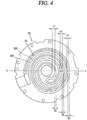
- FIG. 4 is a planar view illustrating a state that a fixed scroll and an orbiting scroll are concentric with each other in a scroll compressor according to the present invention.
- FIG. 5 is a sectional view taken along line 'V-V' in FIG. 4 , which is a longitudinal sectional view for explaining a wrap interval in a coupled state of a fixed scroll to an orbiting scroll.
- a wrap interval (G1) between an outer circumferential surface of a rotation shaft coupling portion 333 which forms a central region of the orbiting scroll 33 and a side surface of a neighboring innermost wrap may be smaller than wrap intervals (G2, G3) between the outer circumferential surface of the rotation shaft coupling portion 333 and neighboring outer wraps.
- the second wrap interval (G2) may be smaller than the third wrap interval (G3).
- a wrap thickness (t1) at the rotation shaft coupling portion 333 may be greater than a wrap thickness (t2) at a neighboring outer side of the rotation shaft coupling portion 333.
- the wrap thickness (t2) may be greater than a wrap thickness (t3) at an outer side of the rotation shaft coupling portion 333.
- the wrap intervals (G1, G2, G3) may be increased toward the edge region of the orbiting scroll 33 from the central region.
- the wrap intervals may be increased toward the edge region of the orbiting scroll from the central region, in a state where the wrap thicknesses are constant.
- the wrap intervals may be increased toward the edge region of the orbiting scroll from the central region, in a state where the wrap thicknesses are increased toward the edge region.
- FIG. 6 is an unfolded view illustrating a wrap thickness from an upper side, in order to explain an embodiment to prevent a partial interference between an orbiting scroll and a fixed scroll in a scroll compressor according to the present invention.
- the orbiting wrap 332 may be offset, such that widths (a1, a1) of two side surfaces 332a,332b on the basis of a center line (CL) of the orbiting wrap 332 may be decreased toward a suction chamber (Vs) from a discharge chamber (Vd). Accordingly, a wrap thickness (t) of the orbiting wrap 32 may be decreased toward a suction chamber side end 332d from a discharge chamber side end 332c.
- the wrap intervals (G1, G2, G3) between the fixed wrap 323 and the orbiting wrap 332 may be gradually increased towards an edge region which forms a suction chamber, from a central region which forms a discharge chamber. That is, a wrap interval between the fixed wrap 323 and the orbiting wrap 332 may be formed as follows.
- a first wrap interval (G1) formed at a central region of the orbiting scroll 33 (or/and the fixed scroll) may be the same as an orbiting radius (r) of the orbiting scroll 33.
- a second wrap interval (G2) formed between the central region and an edge region, and a third wrap interval (G3) formed at the edge region may be larger than the orbiting radius (r) of the orbiting scroll 33.
- the third wrap interval (G3) may be larger than the second wrap interval (G2).
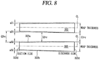
- FIGS. 7 and 8 are unfolded views illustrating a wrap thickness from an upper side, in order to explain another embodiment to prevent a partial interference between an orbiting scroll and a fixed scroll in the scroll compressor of FIG. 1 .
- only one side surface 332b of the two side surfaces of the orbiting wrap 332 may be offset (a2). However, in this case, another side surface which has not been offset may be interfered with a side surface of the fixed wrap 323. In this case, the side surface of the fixed wrap 323 is also offset, preferably. This may prevent a significant decrease of a wrap thickness of the orbiting wrap 332 at a suction chamber side, thereby enhancing reliability.
- two side surfaces of the fixed wrap 323 may be offset (a31, a32), such that a wrap thickness may be decreased toward a suction chamber side end 323d from a discharge chamber side end 323c.
- a wrap interval (G) between the fixed wrap 323 and the orbiting wrap 332 may be gradually increased towards an edge region from a central region of the orbiting scroll 33 (or/and the fixed scroll). This may prevent a significant decrease of a wrap thickness of the orbiting wrap 332 at a suction chamber side, thereby enhancing reliability.
- the orbiting wrap 332 has greater thermal expansion than the fixed wrap 323 even if the fixed wrap 323 and the orbiting wrap 332 are formed of the same material.
- the fixed wrap 323 may be processed such that a wrap thickness thereof may be the same as that according to the original profile.
- the orbiting wrap 332 may be processed such that a wrap thickness thereof may be smaller than that according to the original profile.
- the orbiting scroll 33 is formed of aluminum whereas the fixed scroll 32 is formed of cast-iron, it is preferable to gradually decease the wrap thickness of the orbiting wrap 332 in a suction side direction, because a thermal expansion coefficient of aluminum is larger than that of cast-iron by two times approximately.
- interference between the fixed wrap and the orbiting wrap may be prevented, even if a thermal deformation is increased towards an edge region from a central region due to thermal expansion of the fixed scroll or the orbiting scroll while the scroll compressor is being operated, because a gap between the fixed wrap and the orbiting wrap is gradually increased toward the edge region. This may significantly reduce a frictional loss or abrasion due to interference between the fixed wrap and the orbiting wrap.
- a limitation in selecting materials of the fixed scroll and the orbiting scroll may be reduced, since interference between the fixed scroll and the orbiting scroll due to a thermal transformation of the fixed wrap or the orbiting wrap is reduced. This may allow a light material to be selected without consideration of a thermal transformation even under a high temperature and a high pressure, resulting in enhanced efficiency. Further, since a thermal transformation of the fixed wrap or the orbiting wrap is reduced, a wrap design suitable for a high compression ratio may be implemented.
Landscapes
- Engineering & Computer Science (AREA)
- Mechanical Engineering (AREA)
- General Engineering & Computer Science (AREA)
- Physics & Mathematics (AREA)
- Fluid Mechanics (AREA)
- Rotary Pumps (AREA)
- Applications Or Details Of Rotary Compressors (AREA)
Abstract
Description
- This specification relates to a scroll compressor.
- Generally, a scroll compressor is being widely used at an air conditioner, etc., in order to compress a refrigerant, owing to its advantages that a compression ratio is relatively higher than that of other types of compressors, and a stable torque is obtainable since processes for sucking, compressing and discharging a refrigerant are smoothly performed.
- A behavior characteristic of the scroll compressor is determined by a non-orbiting wrap (hereinafter, will be referred to as a fixed wrap) of a non-orbiting scroll (hereinafter, will be referred to as a fixed scroll) and an orbiting wrap of an orbiting scroll. The fixed wrap and the orbiting wrap may have any shape, but they generally have a shape of an involute curve for easy processing. The involute curve means a curved line corresponding to a moving path drawn by the end of a thread when the thread wound around a basic circle having any radius is unwound. In case of using such an involute curve, the fixed wrap and the orbiting wrap stably perform a relative motion since they have a constant thickness, thereby forming a compression chamber to compress a refrigerant.
- The compression chamber of the scroll compressor has a suction chamber at an outer side and a discharge chamber at an inner side, as a volume of the compression chamber is reduced towards the inner side from the outer side. Thus, the fixed scroll and the orbiting scroll form a high temperature towards the inner side, due to compression heat. Especially, in case of a scroll compressor which satisfies a high temperature and a high compression ratio, an inner compression chamber has a much higher temperature than an outer compression chamber.
- Accordingly, the fixed scroll and the orbiting scroll have a largest thermal expansion ratio at a central region, and a thermal expansion ratio is gradually reduced towards an edge region. However, a total thermal expansion amount is largest at the edge region, since a thermal expansion amount generated from the central region is accumulated at the edge region. Thus, the fixed wrap of the fixed scroll and the orbiting wrap of the orbiting scroll may partially contact each other at the edge region, resulting in a frictional loss. This may cause abrasion of a side surface of the fixed wrap or a side surface of the orbiting wrap, resulting in leakage of a compressed refrigerant. Especially, when the fixed scroll and the orbiting scroll are formed of different materials, for instance, when the fixed scroll is formed of cast-iron and the orbiting scroll is formed of a material having a light weight and a high thermal expansion coefficient (e.g., aluminum), the orbiting scroll has a larger thermal deformation than the fixed scroll. This may significantly increase a frictional loss or abrasion.
- Further, there is a limitation in selecting materials of the fixed scroll and the orbiting scroll. In case of driving the scroll compressor with a high compression ratio, a larger amount of compression heat may be generated to increase a deformation amount of the orbiting scroll. This may cause a limitation in designing the scroll compressor with a high compression ratio.
- Therefore, an aspect of the detailed description is to provide a scroll compressor capable of minimizing a frictional loss or abrasion by preventing interference between a fixed wrap and an orbiting wrap due to thermal expansion.
- Another aspect of the detailed description is to provide a scroll compressor capable of easily selecting materials of a fixed scroll and an orbiting scroll.
- Another aspect of the detailed description is to provide a scroll compressor capable of reducing a limitation in designing a compression ratio.
- To achieve these and other advantages and in accordance with the purpose of this specification, as embodied and broadly described herein, there is provided a scroll compressor, including: a fixed scroll having a fixed wrap; and an orbiting scroll having an orbiting wrap so as to form a compression chamber by being engaged with the fixed wrap, wherein a wrap interval between the fixed wrap and the orbiting wrap is increased towards a suction side from a discharge side of a refrigerant.
- In an embodiment of the present invention, a wrap thickness of the orbiting wrap may be decreased towards a suction side from a discharge side of a refrigerant.
- According to another aspect of the present invention, there is provided a scroll compressor, including: a casing; a driving motor provided at an inner space of the casing; a rotation shaft coupled to a rotor of the driving motor, and rotated together with the rotor; a frame provided below the driving motor; a fixed scroll provided below the frame, and having a fixed wrap; and an orbiting scroll provided between the frame and the fixed scroll, having an orbiting wrap so as to form a compression chamber of a suction chamber, an intermediate pressure chamber and a discharge chamber, by being engaged with the fixed wrap, and having a rotation shaft coupling portion for coupling the rotation shaft thereto in a penetrating manner, wherein in a state where a center of the fixed scroll and a center of the orbiting scroll are consistent with each other, an interval between the fixed wrap and the orbiting wrap is gradually increased towards the suction chamber from the discharge chamber.
- In an embodiment of the present invention, a wrap thickness of the orbiting wrap or the fixed wrap may be gradually decreased towards the suction chamber from the discharge chamber.
- In an embodiment of the present invention, the orbiting wrap or the fixed wrap may be formed such that widths of two side surfaces thereof on the basis of a center line thereof may be decreased.
- In an embodiment of the present invention, the orbiting wrap or the fixed wrap may be formed such that a width of one side surface thereof on the basis of a center line thereof may be decreased.
- In an embodiment of the present invention, the fixed wrap and the orbiting wrap may be formed of different materials.
- In an embodiment of the present invention, the orbiting wrap may be formed of a softer material than the fixed wrap.
- According to another aspect of the present invention, there is provided a scroll compressor, including: a fixed scroll having a fixed plate portion, a fixed wrap protruded from the fixed plate portion, a suction opening formed near an outer side end of the fixed wrap, and one or more discharge openings formed near an inner side end of the fixed wrap; and an orbiting scroll having an orbiting plate portion, and having an orbiting wrap protruded from the orbiting plate portion and coupled to the fixed wrap, the orbiting wrap which forms a compression chamber of a suction chamber, an intermediate pressure chamber and a discharge chamber, towards an inner side from an outer side in a wrap moving direction, together with the fixed plate portion, the fixed wrap and the orbiting plate portion while performing an orbiting motion with respect to the fixed wrap, wherein a wrap interval between the fixed wrap and the orbiting wrap is increased towards the suction chamber from the discharge chamber, in a direction perpendicular to a center line of the fixed wrap or the orbiting wrap.
- In an embodiment of the present invention, in a state where a center of the fixed scroll and a center of the orbiting scroll are consistent with each other, a wrap interval between the fixed wrap and the orbiting wrap may be gradually increased towards the suction chamber from the discharge chamber.
- In an embodiment of the present invention, the fixed wrap and the orbiting wrap may be formed of different materials.
- In an embodiment of the present invention, the orbiting wrap may be formed of a softer material than the fixed wrap.
- According to another aspect of the present invention, there is provided a scroll compressor, including: a fixed scroll having a fixed plate portion, a fixed wrap protruded from the fixed plate portion, a suction opening formed near an outer side end of the fixed wrap, and one or more discharge openings formed near an inner side end of the fixed wrap; and an orbiting scroll having an orbiting plate portion, and having an orbiting wrap protruded from the orbiting plate portion and coupled to the fixed wrap, the orbiting wrap which forms a compression chamber of a suction chamber, an intermediate pressure chamber and a discharge chamber, towards an inner side from an outer side in a wrap moving direction, together with the fixed plate portion, the fixed wrap and the orbiting plate portion while performing an orbiting motion with respect to the fixed wrap, wherein in a state where a center of the fixed scroll and a center of the orbiting scroll are consistent with each other, the fixed wrap and the orbiting wrap are formed such that there exists a region where an interval therebetween in a radius direction is larger than an orbiting radius of the orbiting scroll.
- According to another aspect of the present invention, there is provided a scroll compressor, including: a fixed scroll having a fixed plate portion, a fixed wrap protruded from the fixed plate portion, a suction opening formed near an outer side end of the fixed wrap, and one or more discharge openings formed near an inner side end of the fixed wrap; and an orbiting scroll having an orbiting plate portion, and having an orbiting wrap protruded from the orbiting plate portion and coupled to the fixed wrap, the orbiting wrap which forms a compression chamber of a suction chamber, an intermediate pressure chamber and a discharge chamber, towards an inner side from an outer side in a wrap moving direction, together with the fixed plate portion, the fixed wrap and the orbiting plate portion while performing an orbiting motion with respect to the fixed wrap, wherein an interval between the fixed wrap and the orbiting wrap at a suction side is relatively larger than that at a discharge side.
- In an embodiment of the present invention, the fixed wrap or the orbiting wrap may be formed such that a wrap thickness thereof at a suction side may be relatively smaller than that at a discharge side.
- The compression chamber may include a first compression chamber formed on an inner side surface of the fixed wrap, and a second compression chamber formed on an outer side surface of the fixed wrap. The first compression chamber may be defined between two contact points P11 and P12 generated as the inner side surface of the fixed wrap contacts an outer side surface of the orbiting wrap. And a formula of 0° < α < 360° may be formed, wherein α is an angle defined by two lines which connect a center O of the eccentric portion to the two contact points P1 and P2, respectively.
- The scroll compressor of the present invention may have the following advantages.
- Firstly, interference between the fixed wrap and the orbiting wrap may be prevented, even if a thermal deformation is increased towards an edge region from a central region due to thermal expansion of the fixed scroll or the orbiting scroll while the scroll compressor is being operated, because a gap between the fixed wrap and the orbiting wrap is gradually increased toward the edge region. This may significantly reduce a frictional loss or abrasion due to interference between the fixed wrap and the orbiting wrap.
- Further, a limitation in selecting materials of the fixed scroll and the orbiting scroll may be reduced, since interference between the fixed scroll and the orbiting scroll due to a thermal transformation of the fixed wrap or the orbiting wrap is reduced. This may allow a light material to be selected without consideration of a thermal transformation even under a high temperature and a high pressure, resulting in enhanced efficiency.
- Further, since a thermal transformation of the fixed wrap or the orbiting wrap is reduced, a wrap design suitable for a high compression ratio may be implemented.
- Further scope of applicability of the present application will become more apparent from the detailed description given hereinafter. However, it should be understood that the detailed description and specific examples, while indicating preferred embodiments of the invention, are given by way of illustration only, since various changes and modifications within the spirit and scope of the invention will become apparent to those skilled in the art from the detailed description.
- The accompanying drawings, which are included to provide a further understanding of the invention and are incorporated in and constitute a part of this specification, illustrate exemplary embodiments and together with the description serve to explain the principles of the invention.
- In the drawings:
-
FIG. 1 is a longitudinal sectional view illustrating an example of a lower compression type scroll compressor according to the present invention; -
FIG. 2 is a sectional view taken along line 'IV-IV' inFIG. 1 ; -
FIGS. 3A and 3B are an unfolded view and a planar view, respectively, which illustrate a wrap thickness in order to explain a partial interference between an orbiting scroll and a fixed scroll in the scroll compressor ofFIG. 1 ; -
FIG. 4 is a planar view illustrating a state that a fixed scroll and an orbiting scroll are concentric with each other in a scroll compressor according to the present invention; -
FIG. 5 is a sectional view taken along line 'V-V' inFIG. 4 , which is a longitudinal sectional view for explaining a wrap interval in a coupled state of a fixed scroll to an orbiting scroll; -
FIG. 6 is an unfolded view illustrating a wrap thickness from an upper side, in order to explain an embodiment to prevent a partial interference between an orbiting scroll and a fixed scroll in the scroll compressor ofFIG. 1 ; and -
FIGS. 7 and8 are unfolded views illustrating a wrap thickness from an upper side, in order to explain another embodiment to prevent a partial interference between an orbiting scroll and a fixed scroll in the scroll compressor ofFIG. 1 . - Hereinafter, a scroll compressor according to the present invention will be explained in more detail with reference to the attached drawings. For reference, the scroll compressor according to the present invention is to reduce a frictional loss and abrasion between a fixed wrap and an orbiting wrap due to thermal expansion, by controlling an interval between the fixed wrap and the orbiting wrap. Thus, the present invention may be applied to any type of scroll compressor having a fixed wrap and an orbiting wrap. However, for convenience, will be explained a lower compression type scroll compressor where a compression part is disposed below a motor part, more specifically, a scroll compressor where a rotation shaft is overlapped with an orbiting wrap on the same plane. Such a scroll compressor is appropriate to be applied to a refrigerating cycle of a high temperature and a high compression ratio.
-
FIG. 1 is a longitudinal sectional view illustrating an example of a lower compression type scroll compressor according to the present invention, andFIG. 2 is a sectional view taken along line 'IV-IV' inFIG. 1 . - Referring to
FIG. 1 , the lower compression type scroll compressor according to this embodiment of the present invention may include acasing 1 having an inner space 1a; amotor part 2 provided at the inner space 1a of thecasing 1, and configured to generate a rotational force in the form of a driving motor; acompression part 3 disposed below themotor part 2, and configured to compress a refrigerant by receiving the rotational force of themotor part 2. - The
casing 1 may include acylindrical shell 11 which forms a hermetic container; anupper shell 12 which forms the hermetic container together by covering an upper part of thecylindrical shell 11; and alower shell 13 which forms the hermetic container together by covering a lower part of thecylindrical shell 11, and which forms an oil storage space 1b. - A
refrigerant suction pipe 15 may be penetratingly-formed at a side surface of thecylindrical shell 11, thereby being directly communicated with a suction chamber of thecompression part 3. And arefrigerant discharge pipe 16 communicated with the inner space 1a of thecasing 1 may be installed at an upper part of theupper shell 12. Therefrigerant discharge pipe 16 may be a passage along which a refrigerant compressed by thecompressor 3 and discharged to the inner space 1a of thecasing 1 is discharged to the outside. And an oil separator (not shown) for separating oil mixed with the discharged refrigerant may be connected to therefrigerant discharge pipe 16. - A
stator 21 which constitutes themotor part 2 may be installed at an upper part of thecasing 1, and arotor 22 which constitutes themotor part 2 together with thestator 21 and rotated by a reciprocal operation with thestator 21 may be rotatably installed in thestator 21. - A plurality of slots (not shown) may be formed on an inner circumferential surface of the
stator 21 in a circumferential direction, thereby winding acoil 25 thereon. And anoil collection passage 26 configured to pass oil therethrough may be formed between an outer circumferential surface of thestator 21 and an inner circumferential surface of thecylindrical shell 11, in a D-cut shape. - A
main frame 31 which constitutes thecompression part 3 may be fixed to an inner circumferential surface of thecasing 1, below thestator 21 with a predetermined gap therebetween. Themain frame 31 may be coupled to thecylindrical shell 11 as an outer circumferential surface of themain frame 31 is welded or shrink-fit to an inner circumferential surface of thecylindrical shell 11. - A ring-shaped frame side wall portion (first side wall portion) 311 may be formed at an edge of the
main frame 31, and a firstshaft accommodating portion 312 configured to support amain bearing portion 51 of arotation shaft 5 to be explained later may be formed at a central part of themain frame 31. A firstshaft accommodating hole 312a, configured to rotatably insert themain bearing portion 51 of therotation shaft 5 and support themain bearing portion 51 in a radius direction, may be penetratingly-formed at the firstshaft accommodating portion 312 in an axial direction. - A fixed
scroll 32 may be installed at a bottom surface of themain frame 31, in a state where anorbiting scroll 33 eccentrically-coupled to therotation shaft 5 is disposed between the fixedscroll 32 and themain frame 31. The fixedscroll 32 may be fixedly-coupled to themain frame 31, and may be fixed to themain frame 31 so as to be moveable in an axial direction. - The fixed
scroll 32 may include a fixed plate portion (hereinafter, will be referred to as a first plate portion) 321 formed in an approximate disc shape, and a scroll side wall portion (hereinafter, will be referred to as a second side wall portion) 322 formed at an edge of thefirst plate portion 321 and coupled to an edge of a bottom surface of themain frame 31. - A fixed
wrap 323, which forms a compression chamber (V) by being engaged with anorbiting wrap 332 to be explained later, may be formed on an upper surface of thefirst plate portion 321. The compression chamber (V) may be formed between thefirst plate portion 321 and the fixedwrap 323, and between the orbitingwrap 332 to be explained later and thesecond plate portion 331. And the compression chamber (V) may be implemented as a suction chamber, an intermediate pressure chamber and a discharge chamber are consecutively formed in a moving direction of the wrap. - The compression chamber (V) may include a first compression chamber (V1) formed between an inner side surface of the fixed
wrap 323 and an outer side surface of theorbiting wrap 332, and a second compression chamber (V2) formed between an outer side surface of the fixedwrap 323 and an inner side surface of theorbiting wrap 332. - That is, as shown in
FIG. 2 , the first compression chamber (V1) is formed between two contact points (P11, P12) generated as the inner side surface of the fixedwrap 323 and the outer side surface of theorbiting wrap 332 come in contact with each other. Under an assumption that a largest angle among angles formed by two lines which connect a center (O) of an eccentric portion with two contact points (P11, P12) is α, a formula (a < 360°) is formed before a discharge operation is started. And the second compression chamber (V2) is formed between two contact points (P21, P22) generated as the outer side surface of the fixedwrap 323 and the inner side surface of theorbiting wrap 332 come in contact with each other. - The first compression chamber (V1) is formed such that a refrigerant is firstly sucked thereinto than the second compression chamber (V2), and such that a compression path thereof is relatively long. However, since the
orbiting wrap 332 is formed with irregularity, a compression ration of the first compression chamber (V1) is lower than that of the second compression chamber (V2). Further, the second compression chamber (V2) is formed such that a refrigerant is later sucked thereinto than the first compression chamber (V1), and such that a compression path thereof is relatively short. However, since theorbiting wrap 332 is formed with irregularity, a compression ration of the second compression chamber (V2) is higher than that of the first compression chamber (V1). - A
suction opening 324, through which arefrigerant suction pipe 15 and a suction chamber are communicated with each other, is penetratingly-formed at one side of the secondside wall portion 322. And adischarge opening 325, communicated with a discharge chamber and through which a compressed refrigerant is discharged, may be formed at a central part of thefirst plate portion 321. Thedischarge opening 325 may be formed in one so as to be communicated with both of the first and second compression chambers (V1, V2). Alternatively, thedischarge opening 325 may be formed in plurality so as to be communicated with the first and second compression chambers (V1, V2). - A second
shaft accommodation portion 326, configured to support asub bearing portion 52 of therotation shaft 5 to be explained later, may be formed at a central part of thefirst plate portion 321 of the fixedscroll 32. A secondshaft accommodating hole 326a, configured to support thesub bearing portion 52 in a radius direction, may be penetratingly-formed at the secondshaft accommodating portion 326 in an axial direction. - A
thrust bearing portion 327, configured to support a lower end surface of thesub bearing portion 52 in an axial direction, may be formed at a lower end of the secondshaft accommodation portion 326. Thethrust bearing portion 327 may protrude from a lower end of the secondshaft accommodating hole 326a in a radius direction, towards a shaft center. However, the thrust bearing portion may be formed between a bottom surface of aneccentric portion 53 of therotation shaft 5 to be explained later, and thefirst plate portion 321 of the fixedscroll 32 corresponding thereto. - A
discharge cover 34, configured to accommodate a refrigerant discharged from the compression chamber (V) therein and to guide the refrigerant to a refrigerant passage to be explained later, may be coupled to a lower side of the fixedscroll 32. Thedischarge cover 34 may be formed such that an inner space thereof may accommodate therein thedischarge opening 325 and may accommodate therein an inlet of the refrigerant passage (PG) along which a refrigerant discharged from the compression chamber (V1) is guided to the inner space 1a of thecasing 1. - The refrigerant passage (PG) may be penetratingly-formed at the second
side wall portion 322 of the fixedscroll 32 and the firstside wall portion 311 of themain frame 31, sequentially, at an inner side of an oilpassage separation portion 8. Alternatively, the refrigerant passage (PG) may be formed so as to be consecutively recessed from an outer circumferential surface of the secondside wall portion 322 and an outer circumferential surface of thefirst frame 311. - The orbiting
scroll 33 may be installed between themain frame 31 and the fixedscroll 32 so as to perform an orbiting motion. An Oldham'sring 35 for preventing a rotation of the orbitingscroll 33 may be installed between an upper surface of the orbitingscroll 33 and a bottom surface of themain frame 31 corresponding thereto, and a sealingmember 36 which forms a back pressure chamber (S) may be installed at an inner side than the Oldham'sring 35. Thus, the back pressure chamber (S) may be implemented as a space formed by themain frame 31, the fixedscroll 32 and the orbitingscroll 33, outside the sealingmember 36. The back pressure chamber (S) forms an intermediate pressure because a refrigerant of an intermediate pressure is filled therein as the back pressure chamber (S) is communicated with the intermediate compression chamber (V) by aback pressure hole 321a provided at the fixedscroll 32. However, a space formed at an inner side than the sealingmember 36 may also serve as a back pressure chamber as oil of high pressure is filled therein. - An orbiting plate portion (hereinafter, will be referred to as a second plate portion) 331 of the orbiting
scroll 33 may be formed to have an approximate disc shape. The back pressure chamber (S) may be formed at an upper surface of thesecond plate portion 331, and the orbiting wrap 332 which forms the compression chamber by being engaged with the fixedwrap 322 may be formed at a bottom surface of thesecond plate portion 331. - The
eccentric portion 53 of therotation shaft 5 to be explained later may be rotatably inserted into a central part of thesecond plate portion 331, such that a rotationshaft coupling portion 333 may pass therethrough in an axial direction. - The rotation
shaft coupling portion 333 may be extended from the orbiting wrap 332 so as to form an inner end of theorbiting wrap 332. Thus, since the rotationshaft coupling portion 333 is formed to have a height high enough to be overlapped with the orbiting wrap 332 on the same plane, theeccentric portion 53 of therotation shaft 5 may be overlapped with the orbiting wrap 332 on the same plane. With such a configuration, a repulsive force and a compressive force of a refrigerant are applied to the same plane on the basis of the second plate portion to be attenuated from each other. This may prevent a tilted state of the orbitingscroll 33 due to the compressive force and the repulsive force. - An outer circumference of the rotation
shaft coupling portion 333 is connected to theorbiting wrap 332 to form the compression chamber (V) during a compression operation together with the fixedwrap 322. Theorbiting wrap 332 may be formed to have an involute shape together with the fixedwrap 323. However, theorbiting wrap 332 may be formed to have various shapes. For instance, as shown inFIG. 2 , theorbiting wrap 332 and the fixedwrap 323 may be formed to have a shape implemented as a plurality of circles of different diameters and origin points are connected to each other, and a curved line of an outermost side may be formed as an approximate oval having a long axis and a short axis. - A
protrusion 328 protruded toward an outer circumference of the rotationshaft coupling portion 333, is formed near an inner end (a suction end or a starting end) of the fixedwrap 323. Acontact portion 328a may be protruded from theprotrusion 328. That is, the inner end of the fixedwrap 323 may be formed to have a greater thickness than other parts. With such a configuration, the inner end of the fixedwrap 323, having the largest compressive force among other parts of the fixedwrap 323, may have an enhanced wrap intensity and may have enhanced durability. - A
concaved portion 335, engaged with theprotrusion 328 of the fixedwrap 323, is formed at an outer circumference of the rotationshaft coupling portion 333 which is opposite to the inner end of the fixedwrap 323. Athickness increase portion 335a, having its thickness increased from an inner circumferential part of the rotationshaft coupling portion 333 to an outer circumferential part thereof, is formed at one side of theconcaved portion 335, at an upstream side in a direction to form the compression chambers (V). This may enhance a compression ratio of the first compression chamber (V1) by shortening a length of the first compression chamber (V1) prior to a discharge operation. - A
circular arc surface 335b having a circular arc shape is formed at another side of theconcaved portion 335. A diameter of thecircular arc surface 335b is determined by a thickness of the inner end of the fixedwrap 323 and an orbiting radius of theorbiting wrap 332. If the thickness of the inner end of the fixedwrap 323, the diameter of thecircular arc surface 335b is increased. This may allow the orbiting wrap around thecircular arc surface 335b to have an increased thickness and thus to obtain durability. Further, since a compression path becomes longer, a compression ratio of the second compression chamber (V2) may be increased in correspondence thereto. - The
rotation shaft 5 may be supported in a radius direction as an upper part thereof is forcibly-coupled to a central part of therotor 22, and as a lower part thereof is coupled to thecompression part 3. Thus, therotation shaft 5 transmits a rotational force of themotor part 2 to theorbiting scroll 33 of thecompression part 3. As a result, the orbitingscroll 33 eccentrically-coupled to therotation shaft 5 performs an orbiting motion with respect to the fixedscroll 32. - A
main bearing portion 51, supported in a radius direction by being inserted into the firstshaft accommodating hole 312a of themain frame 31, may be formed at a lower part of therotation shaft 5. And thesub bearing portion 52, supported in a radius direction by being inserted into the secondshaft accommodating hole 326a of the fixedscroll 32, may be formed below themain bearing portion 51. Theeccentric portion 53, inserted into the rotationshaft coupling portion 333 of the orbitingscroll 33, may be formed between themain bearing portion 51 and thesub bearing portion 52. - The
main bearing portion 51 and thesub bearing portion 52 may be formed to be concentric with each other, and theeccentric portion 53 may be formed to be eccentric from themain bearing portion 51 or thesub bearing portion 52 in a radius direction. Thesub bearing portion 52 may be formed to be eccentric from themain bearing portion 51. - An outer diameter of the
eccentric portion 53 may be preferably formed to be smaller than that of themain bearing portion 51 but to be larger than that of thesub bearing portion 52, such that therotation shaft 5 may be easily coupled to theeccentric portion 53 through theshaft accommodating holes shaft coupling portion 333. However, in case of forming theeccentric portion 53 using an additional bearing without integrally forming theeccentric portion 53 with therotation shaft 5, therotation shaft 5 may be coupled to theeccentric portion 53, without the configuration that the outer diameter of theeccentric portion 53 is larger than that of thesub bearing portion 52. - An
oil supply passage 5a, along which oil is supplied to the bearing portions and the eccentric portion, may be formed in therotation shaft 5. As thecompression part 3 is disposed below themotor part 2, theoil supply passage 5a may be formed in a chamfering manner from a lower end of therotation shaft 5 to a lower end of thestator 21 or to an intermediate height of thestator 21, or to a height higher than an upper end of themain bearing portion 51. - An
oil feeder 6, configured to pump oil contained in the oil storage space 1b, may be coupled to a lower end of therotation shaft 5, i.e., a lower end of thesub bearing portion 52. Theoil feeder 6 may include anoil supply pipe 61 insertion-coupled to theoil supply passage 5a of therotation shaft 5, and an oil sucking member 62 (e.g., propeller) inserted into theoil supply pipe 61 and configured to suck oil. Theoil supply pipe 61 may be installed to be immersed in the oil storage space 1b via a thoughhole 341 of thedischarge cover 34. - An oil supply hole and/or an oil supply groove, configured to supply oil sucked through the oil supply passage to an outer circumferential surface of each of the respective bearing portions and the eccentric portion, may be formed at the respective bearing portions and the eccentric portion, or at a position between the respective bearing portions. Thus, oil sucked toward an upper end of the
main bearing portion 51 along theoil supply passage 5a of therotation shaft 5, an oil supply hole (not shown) and an oil supply groove (not shown), flows out of bearing surfaces from an upper end of the firstshaft accommodating portion 312 of themain frame 31. Then, the oil flows down onto an upper surface of themain frame 31, along the firstshaft accommodating portion 312. Then, the oil is collected in the oil storage space 1b, through an oil passage (PO) consecutively formed on an outer circumferential surface of the main frame 31 (or through a groove communicated from the upper surface of themain frame 31 to the outer circumferential surface of the main frame 31) and an outer circumferential surface of the fixedscroll 32. - Further, oil, discharged to the inner space 1a of the
casing 1 from the compression chamber (V) together with a refrigerant, is separated from the refrigerant at an upper space of thecasing 1. Then, the oil is collected in the oil storage space 1b, through a passage formed on an outer circumferential surface of themotor part 2, and through the oil passage (PO) formed on an outer circumferential surface of thecompression part 3. - The lower compression type scroll compressor according to the present invention is operated as follows.
- Firstly, once power is supplied to the
motor part 2, therotor 21 and therotation shaft 5 are rotated as a rotational force is generated. As therotation shaft 5 is rotated, the orbitingscroll 33 eccentrically-coupled to therotation shaft 5 performs an orbiting motion by the Oldham'sring 35. - As a result, the refrigerant supplied from the outside of the
casing 1 through therefrigerant suction pipe 15 is introduced into the compression chambers (V), and the refrigerant is compressed as a volume of the compression chambers (V) is reduced by the orbiting motion of the orbitingscroll 33. Then, the compressed refrigerant is discharged to an inner space of thedischarge cover 34 through thedischarge opening 325. - Then, the refrigerant discharged to the inner space of the
discharge cover 34 circulates at the inner space of thedischarge cover 34, thereby having its noise reduced. Then, the refrigerant moves to a space between themain frame 31 and thestator 21, and moves to an upper space of themotor part 2 through a gap between thestator 21 and therotor 22. - Then, the refrigerant has oil separated therefrom at the upper space of the
motor part 2, and then is discharged to the outside of thecasing 1 through therefrigerant discharge pipe 16. On the other hand, the oil is collected in the oil storage space, a lower space of thecasing 1, through a flow path between an inner circumferential surface of thecasing 1 and thestator 21, and through a flow path between the inner circumferential surface of thecasing 1 and an outer circumferential surface of thecompression part 3. Such processes are repeatedly performed. - The compression chamber (V) formed between the fixed
scroll 32 and the orbitingscroll 33 has a suction chamber at an edge region, and has a discharge chamber at a central region on the basis of the orbitingscroll 33. As a result, the fixedscroll 32 and the orbitingscroll 33 have a highest temperature at the central region. This may cause the fixedscroll 32 and the orbitingscroll 33 to have severe thermal expansion at the central region. Especially, in a case where the orbitingscroll 33 is formed of a soft material such as aluminum, the orbitingscroll 33 may have larger thermal expansion than the fixedscroll 32 formed of cast-iron. Hereinafter, the orbiting scroll will be mainly explained. -
FIGS. 3A and 3B are an unfolded view and a planar view, respectively, which illustrate a wrap thickness in order to explain a partial interference between an orbiting scroll and a fixed scroll in the scroll compressor ofFIG. 1 . due to thermal expansion of the orbiting scroll. - As shown in
FIG. 3A , when a gap (G) between afixed wrap 323 and anorbiting wrap 332 is constant as an orbiting radius, theorbiting wrap 332 and the fixedwrap 323 may be interfered with each other at a section. That is, if thermal expansion occurs at a central region of the orbitingscroll 33 having a discharge chamber, an edge region of the orbitingscroll 33 has a total expansion amount obtained by adding an expansion amount at the central region to an expansion amount at the edge region, since an expansion amount is sequentially accumulated from the central region to the edge region. This may cause an expansion amount to be increased toward the edge region. - Accordingly, as shown in
FIG. 3B , the edge region may have a point where a side surface of the orbiting wrap 332 excessively contacts a side surface of the fixedwrap 323 corresponding thereto. This may cause a frictional loss between contact surfaces of the fixedwrap 323 and theorbiting wrap 332. Especially, severe abrasion may occur on the contact surface of the orbiting wrap 332 formed of a soft material. This may cause theorbiting wrap 332 and the fixedwrap 323 to be widened from each other, resulting in refrigerant leakage and a compression loss. - In order to solve such problems, in this embodiment, a wrap interval (or wrap thickness) of the orbiting wrap is gradually increased from the central region toward the edge region. This may prevent interference between the orbiting wrap and the fixed wrap, even if the orbiting scroll has thermal expansion in a radius direction.
-
FIG. 4 is a planar view illustrating a state that a fixed scroll and an orbiting scroll are concentric with each other in a scroll compressor according to the present invention. AndFIG. 5 is a sectional view taken along line 'V-V' inFIG. 4 , which is a longitudinal sectional view for explaining a wrap interval in a coupled state of a fixed scroll to an orbiting scroll. - As shown in
FIG. 4 , in a state where a center (O) of the fixedscroll 32 and a center (O') of the orbitingscroll 33 are consistent with each other, an interval between thefixed wrap 323 and theorbiting wrap 332 will be explained. A wrap interval (G1) between an outer circumferential surface of a rotationshaft coupling portion 333 which forms a central region of the orbitingscroll 33 and a side surface of a neighboring innermost wrap may be smaller than wrap intervals (G2, G3) between the outer circumferential surface of the rotationshaft coupling portion 333 and neighboring outer wraps. In this case, the second wrap interval (G2) may be smaller than the third wrap interval (G3). - For this, a wrap thickness (t1) at the rotation
shaft coupling portion 333 may be greater than a wrap thickness (t2) at a neighboring outer side of the rotationshaft coupling portion 333. And the wrap thickness (t2) may be greater than a wrap thickness (t3) at an outer side of the rotationshaft coupling portion 333. Accordingly, the wrap intervals (G1, G2, G3) may be increased toward the edge region of the orbitingscroll 33 from the central region. However, in some cases, the wrap intervals may be increased toward the edge region of the orbiting scroll from the central region, in a state where the wrap thicknesses are constant. Alternatively, the wrap intervals may be increased toward the edge region of the orbiting scroll from the central region, in a state where the wrap thicknesses are increased toward the edge region. -
FIG. 6 is an unfolded view illustrating a wrap thickness from an upper side, in order to explain an embodiment to prevent a partial interference between an orbiting scroll and a fixed scroll in a scroll compressor according to the present invention. - As shown in
FIG. 6 , theorbiting wrap 332 may be offset, such that widths (a1, a1) of twoside surfaces orbiting wrap 332 may be decreased toward a suction chamber (Vs) from a discharge chamber (Vd). Accordingly, a wrap thickness (t) of the orbitingwrap 32 may be decreased toward a suctionchamber side end 332d from a discharge chamber side end 332c. - Accordingly, as shown in
FIG. 5 , the wrap intervals (G1, G2, G3) between thefixed wrap 323 and theorbiting wrap 332 may be gradually increased towards an edge region which forms a suction chamber, from a central region which forms a discharge chamber. That is, a wrap interval between thefixed wrap 323 and theorbiting wrap 332 may be formed as follows. A first wrap interval (G1) formed at a central region of the orbiting scroll 33 (or/and the fixed scroll) may be the same as an orbiting radius (r) of the orbitingscroll 33. A second wrap interval (G2) formed between the central region and an edge region, and a third wrap interval (G3) formed at the edge region may be larger than the orbiting radius (r) of the orbitingscroll 33. In this case, the third wrap interval (G3) may be larger than the second wrap interval (G2). - With such a configuration, even if thermal deformation of the orbiting wrap is accumulated in a radius direction (a wrap thickness direction) due to thermal expansion towards the edge region from the central region, a gap between the
fixed wrap 323 and the orbiting wrap 332 at the edge region is sufficiently obtained. This may prevent an excessive contact between a side surface of the fixedwrap 323 and a side surface of the orbiting wrap 332 corresponding thereto. - Hereinafter, will be explained another embodiment to increase a wrap interval towards an edge region from a central region in a scroll compressor according to the present invention.
FIGS. 7 and8 are unfolded views illustrating a wrap thickness from an upper side, in order to explain another embodiment to prevent a partial interference between an orbiting scroll and a fixed scroll in the scroll compressor ofFIG. 1 . - As shown in
FIG. 7 , only oneside surface 332b of the two side surfaces of theorbiting wrap 332 may be offset (a2). However, in this case, another side surface which has not been offset may be interfered with a side surface of the fixedwrap 323. In this case, the side surface of the fixedwrap 323 is also offset, preferably. This may prevent a significant decrease of a wrap thickness of the orbiting wrap 332 at a suction chamber side, thereby enhancing reliability. - As shown in
FIG. 8 , like theorbiting wrap 332, two side surfaces of the fixedwrap 323 may be offset (a31, a32), such that a wrap thickness may be decreased toward a suctionchamber side end 323d from a discharge chamber side end 323c. As a result, a wrap interval (G) between thefixed wrap 323 and theorbiting wrap 332 may be gradually increased towards an edge region from a central region of the orbiting scroll 33 (or/and the fixed scroll). This may prevent a significant decrease of a wrap thickness of the orbiting wrap 332 at a suction chamber side, thereby enhancing reliability. - The
orbiting wrap 332 has greater thermal expansion than the fixedwrap 323 even if the fixedwrap 323 and theorbiting wrap 332 are formed of the same material. Considering this, the fixedwrap 323 may be processed such that a wrap thickness thereof may be the same as that according to the original profile. On the other hand, theorbiting wrap 332 may be processed such that a wrap thickness thereof may be smaller than that according to the original profile. In a case where the orbitingscroll 33 is formed of aluminum whereas the fixedscroll 32 is formed of cast-iron, it is preferable to gradually decease the wrap thickness of theorbiting wrap 332 in a suction side direction, because a thermal expansion coefficient of aluminum is larger than that of cast-iron by two times approximately. - With such a configuration, interference between the fixed wrap and the orbiting wrap may be prevented, even if a thermal deformation is increased towards an edge region from a central region due to thermal expansion of the fixed scroll or the orbiting scroll while the scroll compressor is being operated, because a gap between the fixed wrap and the orbiting wrap is gradually increased toward the edge region. This may significantly reduce a frictional loss or abrasion due to interference between the fixed wrap and the orbiting wrap.
- Further, a limitation in selecting materials of the fixed scroll and the orbiting scroll may be reduced, since interference between the fixed scroll and the orbiting scroll due to a thermal transformation of the fixed wrap or the orbiting wrap is reduced. This may allow a light material to be selected without consideration of a thermal transformation even under a high temperature and a high pressure, resulting in enhanced efficiency. Further, since a thermal transformation of the fixed wrap or the orbiting wrap is reduced, a wrap design suitable for a high compression ratio may be implemented.
- Further embodiments of the present invention are described by the following items:
- 1. A scroll compressor, comprising:
- a casing (1);
- a driving motor (2) provided at an inner space of the casing;
- a rotation shaft (5) coupled to a rotor (22) of the driving motor, and rotated together with the rotor;
- a fixed scroll (32) having a fixed wrap (323); and
- an orbiting scroll (33) having an orbiting wrap (332) so as to form a compression chamber (V) of a suction chamber, an intermediate pressure chamber and a discharge chamber, by being engaged with the fixed wrap (323), and having a rotation shaft coupling portion (333) for coupling the rotation shaft (5) thereto in a penetrating manner,
- wherein in a state where a center of the fixed scroll (32) and a center of the orbiting scroll (33) are consistent with each other, an interval (t1, t2, t3) between the fixed wrap (323) and the orbiting wrap (332) is gradually increased towards the suction chamber (Vs) from the discharge chamber (Vd).
- 2. The scroll compressor of
item 1, wherein a wrap thickness of the orbiting wrap or the fixed wrap is gradually decreased towards the suction chamber from the discharge chamber. - 3. The scroll compressor of
item - 4. The scroll compressor of
item - 5. The scroll compressor of one of
items 1 to 4, wherein the fixed wrap and the orbiting wrap are formed of different materials. - 6. The scroll compressor of
item 5, wherein the orbiting wrap is formed of a softer material than the fixed wrap. - 7. The scroll compressor of one of
items 1 to 6, wherein a wrap interval between the fixed wrap and the orbiting wrap is increased towards the suction chamber from the discharge chamber, in a direction perpendicular to a center line of the orbiting wrap. - 8. The scroll compressor of item 7, wherein in a state where a center of the fixed scroll and a center of the orbiting scroll are consistent with each other, a wrap interval between the fixed wrap and the orbiting wrap is gradually increased towards the suction chamber from the discharge chamber.
- 9. The scroll compressor of
item 1, wherein in a state where a center of the fixed scroll and a center of the orbiting scroll are consistent with each other, the fixed wrap and the orbiting wrap are formed such that there exists a region where an interval therebetween in a radius direction is larger than an orbiting radius of the orbiting scroll. - 10. The scroll compressor of
item 1, wherein an interval between the fixed wrap and the orbiting wrap at a suction side is relatively larger than that at a discharge side. - 11. The scroll compressor of item 9 or 10, wherein the fixed wrap or the orbiting wrap is formed such that a wrap thickness (t1, t2, t3) thereof at a suction side is relatively smaller than that at a discharge side.
- 12. The scroll compressor of
item 1, wherein an interval between the fixed wrap and the orbiting wrap is increased towards a suction side from a discharge side, on the basis of a flowing direction of a refrigerant. - 13. The scroll compressor of
item 12, wherein a thickness of the orbiting wrap is decreased towards a suction side from a discharge side, on the basis of a flowing direction of a refrigerant. - 14. The scroll compressor of one of
items 1 to 13, wherein the fixed scroll is provided below the driving motor.
Claims (13)
- A compressor, comprising:A casing (1);A drive motor (2) provided in the inner space of the casing;A rotating shaft (5) coupled to the driving motor to rotate;An orbiting scroll (33) including an orbiting plate portion (331) coupled to the rotating shaft (5) and an orbiting wrap (332) extending along a circumference direction of the orbiting plate portion;A fixed scroll (32) comprising a fixed wrap (322) provided in engagement with the orbiting wrap to compress a refrigerant, a fixed plate portion (321) including a suction opening (324) receiving the refrigerant and a discharge opening (325) spaced apart from the suction opening to discharge the refrigerant;wherein the thickness of the orbiting wrap facing the suction opening is thinner than the thickness of the orbiting wrap facing the discharge opening.
- The compressor according to claim 1, wherein the discharge opening (325) is disposed adjacent to the rotating shaft on the fixed plate portion (321),
wherein the suction opening (324) is spaced apart from the discharge opening (325) toward the casing (1). - The compressor according to claim 1 or 2, wherein the orbiting wrap (332) is provided to be thicker as it extends from the suction opening (324) toward the discharge opening (325).
- The compressor according to any of claims 1 to 3, wherein the orbiting wrap (332) is provided so that the thickness gradually becomes thinner from the region extending 90 degrees from the suction opening (324) with respect to rotating shaft (5) to the region extending 180 degrees.
- The compressor according to any of claims 1 to 4, wherein the orbiting scroll (33) further includes a rotation shaft coupling portion (333) coupled to the rotation shaft, wherein the orbiting wrap (332) is provided extending from the rotation shaft coupling portion (333) toward the case along the circumference of the orbiting plate portion.
- The compressor according to claim 5, wherein the rotation shaft coupling portion (333) is provided to be penetrated by the rotating shaft (5).
- The compressor according to claim 5 or 6, wherein the discharge opening (325) is provided to spaced apart from the rotation shaft coupling portion (333).
- The compressor according to any of claims 5 to 7, wherein the thickness of the orbiting wrap (332) facing the suction opening (324) is provided to be thinner than the thickness of the rotation shaft coupling portion (333).
- The compressor according to claim 8, wherein the thickness of the orbiting wrap (332) facing the suction opening (324) is provided to be thinner than the thickness of the rotation shaft coupling portion (333).
- The compressor according to any of claims 1 to 4, wherein the spacing between the orbiting wrap facing the suction opening (324) and the fixed wrap (322) is greater than the spacing between the orbiting wrap (332) facing the discharge opening (325) and the fixed wrap (322).
- The compressor according to claim 10, wherein the orbiting scroll (33) further includes a rotation shaft coupling portion (333) coupled to the rotation shaft, wherein the orbiting wrap (332) is provided extending from the rotation shaft coupling portion (333) toward the casing (1) along the circumference of the orbiting plate portion (331).
- The compressor according to claim 11, wherein the rotation shaft coupling portion (333) is provided to be penetrated by the rotating shaft (5).
- The compressor according to claim 11 or 12, wherein the discharge opening (325) is provided to spaced apart from the rotation shaft coupling portion (333).
Applications Claiming Priority (2)
| Application Number | Priority Date | Filing Date | Title |
|---|---|---|---|
| KR1020160051038A KR102481368B1 (en) | 2016-04-26 | 2016-04-26 | Scroll compressor |
| EP17165727.3A EP3239527B1 (en) | 2016-04-26 | 2017-04-10 | Scroll compressor |
Related Parent Applications (1)
| Application Number | Title | Priority Date | Filing Date |
|---|---|---|---|
| EP17165727.3A Division EP3239527B1 (en) | 2016-04-26 | 2017-04-10 | Scroll compressor |
Publications (2)
| Publication Number | Publication Date |
|---|---|
| EP3696419A1 true EP3696419A1 (en) | 2020-08-19 |
| EP3696419B1 EP3696419B1 (en) | 2025-01-15 |
Family
ID=58530446
Family Applications (2)
| Application Number | Title | Priority Date | Filing Date |
|---|---|---|---|
| EP20160652.2A Active EP3696419B1 (en) | 2016-04-26 | 2017-04-10 | Scroll compressor |
| EP17165727.3A Active EP3239527B1 (en) | 2016-04-26 | 2017-04-10 | Scroll compressor |
Family Applications After (1)
| Application Number | Title | Priority Date | Filing Date |
|---|---|---|---|
| EP17165727.3A Active EP3239527B1 (en) | 2016-04-26 | 2017-04-10 | Scroll compressor |
Country Status (5)
| Country | Link |
|---|---|
| US (2) | US10724521B2 (en) |
| EP (2) | EP3696419B1 (en) |
| KR (2) | KR102481368B1 (en) |
| CN (1) | CN107313930B (en) |
| WO (1) | WO2017188573A1 (en) |
Families Citing this family (9)
| Publication number | Priority date | Publication date | Assignee | Title |
|---|---|---|---|---|
| KR102492941B1 (en) * | 2018-05-10 | 2023-01-27 | 엘지전자 주식회사 | Compressor having enhanced wrap structure |
| KR102070784B1 (en) * | 2018-07-13 | 2020-01-29 | 엘지전자 주식회사 | A compressor |
| US11530856B2 (en) * | 2018-12-17 | 2022-12-20 | Trane International Inc. | Systems and methods for controlling compressor motors |
| JP6863405B2 (en) | 2019-05-21 | 2021-04-21 | ダイキン工業株式会社 | Scroll compressor and refrigerator equipped with it |
| EP3990785B1 (en) * | 2019-07-30 | 2024-10-30 | Samsung Electronics Co., Ltd. | Scroll compressor |
| KR102309304B1 (en) | 2019-11-05 | 2021-10-07 | 엘지전자 주식회사 | Compressor |
| KR102815012B1 (en) * | 2020-01-10 | 2025-06-04 | 엘지전자 주식회사 | A compressor |
| KR20210129535A (en) | 2020-04-20 | 2021-10-28 | 엘지전자 주식회사 | A compressor |
| JP7281017B2 (en) * | 2020-07-20 | 2023-05-24 | 株式会社日立産機システム | scroll compressor |
Citations (6)
| Publication number | Priority date | Publication date | Assignee | Title |
|---|---|---|---|---|
| EP0049495A1 (en) * | 1980-10-03 | 1982-04-14 | Sanden Corporation | Scroll type fluid displacement apparatus |
| US5151020A (en) * | 1990-09-13 | 1992-09-29 | Kabushiki Kaisha Toyoda Jidoshokki Seisakusho | Scroll type compressor having gradually thinned wall thickness |
| JP2009174406A (en) * | 2008-01-24 | 2009-08-06 | Panasonic Corp | Scroll compressor |
| US20130004354A1 (en) * | 2011-07-01 | 2013-01-03 | Lg Electronics Inc. | Scroll compressor |
| EP2813706A1 (en) * | 2013-06-10 | 2014-12-17 | LG Electronics, Inc. | Scroll compressor |
| US20160040672A1 (en) * | 2014-08-07 | 2016-02-11 | Lg Electronics Inc. | Compressor |
Family Cites Families (17)
| Publication number | Priority date | Publication date | Assignee | Title |
|---|---|---|---|---|
| US3874827A (en) * | 1973-10-23 | 1975-04-01 | Niels O Young | Positive displacement scroll apparatus with axially radially compliant scroll member |
| DE3719950A1 (en) * | 1987-06-15 | 1989-01-05 | Agintec Ag | DISPLACEMENT MACHINE |
| KR0168867B1 (en) * | 1991-12-20 | 1999-01-15 | 가나이 쯔또무 | Scroll type fluid machine, scroll member and processing method |
| JP3539189B2 (en) * | 1998-03-10 | 2004-07-07 | 株式会社日立製作所 | Scroll fluid machine |
| JP2000110719A (en) * | 1998-10-05 | 2000-04-18 | Matsushita Electric Ind Co Ltd | Hermetic and open compressors |
| US6149411A (en) * | 1999-01-27 | 2000-11-21 | Carrier Corporation | Variable flank relief for scroll wraps |
| JP2003328966A (en) * | 2002-05-15 | 2003-11-19 | Matsushita Electric Ind Co Ltd | Scroll compressor |
| JP4440565B2 (en) * | 2003-06-24 | 2010-03-24 | パナソニック株式会社 | Scroll compressor |
| JP5030581B2 (en) * | 2006-12-28 | 2012-09-19 | 三菱重工業株式会社 | Scroll compressor |
| WO2010013351A1 (en) * | 2008-07-28 | 2010-02-04 | 株式会社リッチストーン | Scroll fluid machine |
| KR101810461B1 (en) | 2011-03-24 | 2017-12-19 | 엘지전자 주식회사 | Scroll compressor |
| EP2696994B1 (en) | 2011-04-13 | 2021-08-18 | Koninklijke Philips N.V. | Temperature compensation in a cmut device |
| KR101480472B1 (en) | 2011-09-28 | 2015-01-09 | 엘지전자 주식회사 | Scroll compressor |
| KR101368396B1 (en) * | 2011-11-09 | 2014-03-03 | 엘지전자 주식회사 | Scroll compressor |
| JP6195466B2 (en) * | 2013-05-08 | 2017-09-13 | 三菱電機株式会社 | Scroll compressor |
| US9920760B2 (en) * | 2014-05-23 | 2018-03-20 | Lg Electronics Inc. | Scroll compressor |
| KR102245438B1 (en) * | 2014-08-19 | 2021-04-29 | 엘지전자 주식회사 | compressor |
-
2016
- 2016-04-26 KR KR1020160051038A patent/KR102481368B1/en active Active
-
2017
- 2017-02-15 WO PCT/KR2017/001675 patent/WO2017188573A1/en not_active Ceased
- 2017-03-30 CN CN201710203453.8A patent/CN107313930B/en active Active
- 2017-04-10 EP EP20160652.2A patent/EP3696419B1/en active Active
- 2017-04-10 EP EP17165727.3A patent/EP3239527B1/en active Active
- 2017-04-19 US US15/491,009 patent/US10724521B2/en active Active
-
2019
- 2019-11-25 US US16/693,467 patent/US11668303B2/en active Active
-
2022
- 2022-12-21 KR KR1020220180502A patent/KR102639609B1/en active Active
Patent Citations (6)
| Publication number | Priority date | Publication date | Assignee | Title |
|---|---|---|---|---|
| EP0049495A1 (en) * | 1980-10-03 | 1982-04-14 | Sanden Corporation | Scroll type fluid displacement apparatus |
| US5151020A (en) * | 1990-09-13 | 1992-09-29 | Kabushiki Kaisha Toyoda Jidoshokki Seisakusho | Scroll type compressor having gradually thinned wall thickness |
| JP2009174406A (en) * | 2008-01-24 | 2009-08-06 | Panasonic Corp | Scroll compressor |
| US20130004354A1 (en) * | 2011-07-01 | 2013-01-03 | Lg Electronics Inc. | Scroll compressor |
| EP2813706A1 (en) * | 2013-06-10 | 2014-12-17 | LG Electronics, Inc. | Scroll compressor |
| US20160040672A1 (en) * | 2014-08-07 | 2016-02-11 | Lg Electronics Inc. | Compressor |
Also Published As
| Publication number | Publication date |
|---|---|
| EP3696419B1 (en) | 2025-01-15 |
| WO2017188573A1 (en) | 2017-11-02 |
| KR102639609B1 (en) | 2024-02-26 |
| US11668303B2 (en) | 2023-06-06 |
| KR20170122011A (en) | 2017-11-03 |
| KR102481368B1 (en) | 2022-12-26 |
| CN107313930B (en) | 2020-09-08 |
| US20170306953A1 (en) | 2017-10-26 |
| CN107313930A (en) | 2017-11-03 |
| US20200102957A1 (en) | 2020-04-02 |
| US10724521B2 (en) | 2020-07-28 |
| EP3239527B1 (en) | 2020-03-04 |
| KR20230005080A (en) | 2023-01-09 |
| EP3239527A1 (en) | 2017-11-01 |
Similar Documents
| Publication | Publication Date | Title |
|---|---|---|
| EP3239527B1 (en) | Scroll compressor | |
| US20220282731A1 (en) | Scroll compressor with recesses and protrusions | |
| EP3239529B1 (en) | Scroll compressor | |
| EP3450761B1 (en) | Scroll compressor | |
| KR102234708B1 (en) | compressor | |
| US11920590B2 (en) | Scroll compressor | |
| US11015596B2 (en) | Scroll compressor sealing | |
| EP3239458B1 (en) | Scroll compressor | |
| US11181109B2 (en) | Scroll compressor | |
| KR102565824B1 (en) | Scroll compressor | |
| KR20190000687A (en) | Compressor having enhaced lubrication structre |
Legal Events
| Date | Code | Title | Description |
|---|---|---|---|
| PUAI | Public reference made under article 153(3) epc to a published international application that has entered the european phase |
Free format text: ORIGINAL CODE: 0009012 |
|
| STAA | Information on the status of an ep patent application or granted ep patent |
Free format text: STATUS: REQUEST FOR EXAMINATION WAS MADE |
|
| 17P | Request for examination filed |
Effective date: 20200331 |
|
| AC | Divisional application: reference to earlier application |
Ref document number: 3239527 Country of ref document: EP Kind code of ref document: P |
|
| AK | Designated contracting states |
Kind code of ref document: A1 Designated state(s): AL AT BE BG CH CY CZ DE DK EE ES FI FR GB GR HR HU IE IS IT LI LT LU LV MC MK MT NL NO PL PT RO RS SE SI SK SM TR |
|
| RBV | Designated contracting states (corrected) |
Designated state(s): AL AT BE BG CH CY CZ DE DK EE ES FI FR GB GR HR HU IE IS IT LI LT LU LV MC MK MT NL NO PL PT RO RS SE SI SK SM TR |
|
| STAA | Information on the status of an ep patent application or granted ep patent |
Free format text: STATUS: EXAMINATION IS IN PROGRESS |
|
| 17Q | First examination report despatched |
Effective date: 20210420 |
|
| GRAP | Despatch of communication of intention to grant a patent |
Free format text: ORIGINAL CODE: EPIDOSNIGR1 |
|
| STAA | Information on the status of an ep patent application or granted ep patent |
Free format text: STATUS: GRANT OF PATENT IS INTENDED |
|
| INTG | Intention to grant announced |
Effective date: 20240808 |
|
| GRAS | Grant fee paid |
Free format text: ORIGINAL CODE: EPIDOSNIGR3 |
|
| GRAA | (expected) grant |
Free format text: ORIGINAL CODE: 0009210 |
|
| STAA | Information on the status of an ep patent application or granted ep patent |
Free format text: STATUS: THE PATENT HAS BEEN GRANTED |
|
| AC | Divisional application: reference to earlier application |
Ref document number: 3239527 Country of ref document: EP Kind code of ref document: P |
|
| AK | Designated contracting states |
Kind code of ref document: B1 Designated state(s): AL AT BE BG CH CY CZ DE DK EE ES FI FR GB GR HR HU IE IS IT LI LT LU LV MC MK MT NL NO PL PT RO RS SE SI SK SM TR |
|
| REG | Reference to a national code |
Ref country code: CH Ref legal event code: EP Ref country code: GB Ref legal event code: FG4D |
|
| REG | Reference to a national code |
Ref country code: DE Ref legal event code: R096 Ref document number: 602017087394 Country of ref document: DE |
|
| REG | Reference to a national code |
Ref country code: IE Ref legal event code: FG4D |
|
| REG | Reference to a national code |
Ref country code: NL Ref legal event code: MP Effective date: 20250115 |
|
| PG25 | Lapsed in a contracting state [announced via postgrant information from national office to epo] |
Ref country code: NL Free format text: LAPSE BECAUSE OF FAILURE TO SUBMIT A TRANSLATION OF THE DESCRIPTION OR TO PAY THE FEE WITHIN THE PRESCRIBED TIME-LIMIT Effective date: 20250115 |
|
| PG25 | Lapsed in a contracting state [announced via postgrant information from national office to epo] |
Ref country code: RS Free format text: LAPSE BECAUSE OF FAILURE TO SUBMIT A TRANSLATION OF THE DESCRIPTION OR TO PAY THE FEE WITHIN THE PRESCRIBED TIME-LIMIT Effective date: 20250415 |
|
| PG25 | Lapsed in a contracting state [announced via postgrant information from national office to epo] |
Ref country code: FI Free format text: LAPSE BECAUSE OF FAILURE TO SUBMIT A TRANSLATION OF THE DESCRIPTION OR TO PAY THE FEE WITHIN THE PRESCRIBED TIME-LIMIT Effective date: 20250115 |
|
| PG25 | Lapsed in a contracting state [announced via postgrant information from national office to epo] |
Ref country code: PL Free format text: LAPSE BECAUSE OF FAILURE TO SUBMIT A TRANSLATION OF THE DESCRIPTION OR TO PAY THE FEE WITHIN THE PRESCRIBED TIME-LIMIT Effective date: 20250115 |
|
| PGFP | Annual fee paid to national office [announced via postgrant information from national office to epo] |
Ref country code: DE Payment date: 20250305 Year of fee payment: 9 |
|
| PG25 | Lapsed in a contracting state [announced via postgrant information from national office to epo] |
Ref country code: ES Free format text: LAPSE BECAUSE OF FAILURE TO SUBMIT A TRANSLATION OF THE DESCRIPTION OR TO PAY THE FEE WITHIN THE PRESCRIBED TIME-LIMIT Effective date: 20250115 |
|
| REG | Reference to a national code |
Ref country code: LT Ref legal event code: MG9D |
|
| PG25 | Lapsed in a contracting state [announced via postgrant information from national office to epo] |
Ref country code: IS Free format text: LAPSE BECAUSE OF FAILURE TO SUBMIT A TRANSLATION OF THE DESCRIPTION OR TO PAY THE FEE WITHIN THE PRESCRIBED TIME-LIMIT Effective date: 20250515 Ref country code: NO Free format text: LAPSE BECAUSE OF FAILURE TO SUBMIT A TRANSLATION OF THE DESCRIPTION OR TO PAY THE FEE WITHIN THE PRESCRIBED TIME-LIMIT Effective date: 20250415 |
|
| REG | Reference to a national code |
Ref country code: AT Ref legal event code: MK05 Ref document number: 1759995 Country of ref document: AT Kind code of ref document: T Effective date: 20250115 |
|
| PG25 | Lapsed in a contracting state [announced via postgrant information from national office to epo] |
Ref country code: HR Free format text: LAPSE BECAUSE OF FAILURE TO SUBMIT A TRANSLATION OF THE DESCRIPTION OR TO PAY THE FEE WITHIN THE PRESCRIBED TIME-LIMIT Effective date: 20250115 |
|
| PG25 | Lapsed in a contracting state [announced via postgrant information from national office to epo] |
Ref country code: LV Free format text: LAPSE BECAUSE OF FAILURE TO SUBMIT A TRANSLATION OF THE DESCRIPTION OR TO PAY THE FEE WITHIN THE PRESCRIBED TIME-LIMIT Effective date: 20250115 Ref country code: PT Free format text: LAPSE BECAUSE OF FAILURE TO SUBMIT A TRANSLATION OF THE DESCRIPTION OR TO PAY THE FEE WITHIN THE PRESCRIBED TIME-LIMIT Effective date: 20250515 |
|
| PG25 | Lapsed in a contracting state [announced via postgrant information from national office to epo] |
Ref country code: BG Free format text: LAPSE BECAUSE OF FAILURE TO SUBMIT A TRANSLATION OF THE DESCRIPTION OR TO PAY THE FEE WITHIN THE PRESCRIBED TIME-LIMIT Effective date: 20250115 Ref country code: GR Free format text: LAPSE BECAUSE OF FAILURE TO SUBMIT A TRANSLATION OF THE DESCRIPTION OR TO PAY THE FEE WITHIN THE PRESCRIBED TIME-LIMIT Effective date: 20250416 |
|
| PG25 | Lapsed in a contracting state [announced via postgrant information from national office to epo] |
Ref country code: AT Free format text: LAPSE BECAUSE OF FAILURE TO SUBMIT A TRANSLATION OF THE DESCRIPTION OR TO PAY THE FEE WITHIN THE PRESCRIBED TIME-LIMIT Effective date: 20250115 |
|
| PG25 | Lapsed in a contracting state [announced via postgrant information from national office to epo] |
Ref country code: SE Free format text: LAPSE BECAUSE OF FAILURE TO SUBMIT A TRANSLATION OF THE DESCRIPTION OR TO PAY THE FEE WITHIN THE PRESCRIBED TIME-LIMIT Effective date: 20250115 |
|
| PG25 | Lapsed in a contracting state [announced via postgrant information from national office to epo] |
Ref country code: SM Free format text: LAPSE BECAUSE OF FAILURE TO SUBMIT A TRANSLATION OF THE DESCRIPTION OR TO PAY THE FEE WITHIN THE PRESCRIBED TIME-LIMIT Effective date: 20250115 |
|
| PG25 | Lapsed in a contracting state [announced via postgrant information from national office to epo] |
Ref country code: DK Free format text: LAPSE BECAUSE OF FAILURE TO SUBMIT A TRANSLATION OF THE DESCRIPTION OR TO PAY THE FEE WITHIN THE PRESCRIBED TIME-LIMIT Effective date: 20250115 |
|
| PG25 | Lapsed in a contracting state [announced via postgrant information from national office to epo] |
Ref country code: IT Free format text: LAPSE BECAUSE OF FAILURE TO SUBMIT A TRANSLATION OF THE DESCRIPTION OR TO PAY THE FEE WITHIN THE PRESCRIBED TIME-LIMIT Effective date: 20250115 |
|
| REG | Reference to a national code |
Ref country code: DE Ref legal event code: R097 Ref document number: 602017087394 Country of ref document: DE |
|
| PG25 | Lapsed in a contracting state [announced via postgrant information from national office to epo] |
Ref country code: CZ Free format text: LAPSE BECAUSE OF FAILURE TO SUBMIT A TRANSLATION OF THE DESCRIPTION OR TO PAY THE FEE WITHIN THE PRESCRIBED TIME-LIMIT Effective date: 20250115 Ref country code: EE Free format text: LAPSE BECAUSE OF FAILURE TO SUBMIT A TRANSLATION OF THE DESCRIPTION OR TO PAY THE FEE WITHIN THE PRESCRIBED TIME-LIMIT Effective date: 20250115 |
|
| PG25 | Lapsed in a contracting state [announced via postgrant information from national office to epo] |
Ref country code: RO Free format text: LAPSE BECAUSE OF FAILURE TO SUBMIT A TRANSLATION OF THE DESCRIPTION OR TO PAY THE FEE WITHIN THE PRESCRIBED TIME-LIMIT Effective date: 20250115 |
|
| PG25 | Lapsed in a contracting state [announced via postgrant information from national office to epo] |
Ref country code: SK Free format text: LAPSE BECAUSE OF FAILURE TO SUBMIT A TRANSLATION OF THE DESCRIPTION OR TO PAY THE FEE WITHIN THE PRESCRIBED TIME-LIMIT Effective date: 20250115 |
|
| PLBE | No opposition filed within time limit |
Free format text: ORIGINAL CODE: 0009261 |
|
| STAA | Information on the status of an ep patent application or granted ep patent |
Free format text: STATUS: NO OPPOSITION FILED WITHIN TIME LIMIT |
|
| REG | Reference to a national code |
Ref country code: CH Ref legal event code: H13 Free format text: ST27 STATUS EVENT CODE: U-0-0-H10-H13 (AS PROVIDED BY THE NATIONAL OFFICE) Effective date: 20251125 |
|
| REG | Reference to a national code |
Ref country code: CH Ref legal event code: L10 Free format text: ST27 STATUS EVENT CODE: U-0-0-L10-L00 (AS PROVIDED BY THE NATIONAL OFFICE) Effective date: 20251126 |
|
| PG25 | Lapsed in a contracting state [announced via postgrant information from national office to epo] |
Ref country code: LU Free format text: LAPSE BECAUSE OF NON-PAYMENT OF DUE FEES Effective date: 20250410 |
|
| PG25 | Lapsed in a contracting state [announced via postgrant information from national office to epo] |
Ref country code: MC Free format text: LAPSE BECAUSE OF FAILURE TO SUBMIT A TRANSLATION OF THE DESCRIPTION OR TO PAY THE FEE WITHIN THE PRESCRIBED TIME-LIMIT Effective date: 20250115 |
|
| 26N | No opposition filed |
Effective date: 20251016 |
|
| GBPC | Gb: european patent ceased through non-payment of renewal fee |
Effective date: 20250415 |
|
| REG | Reference to a national code |
Ref country code: BE Ref legal event code: MM Effective date: 20250430 |
|
| PG25 | Lapsed in a contracting state [announced via postgrant information from national office to epo] |
Ref country code: GB Free format text: LAPSE BECAUSE OF NON-PAYMENT OF DUE FEES Effective date: 20250415 |
|
| PG25 | Lapsed in a contracting state [announced via postgrant information from national office to epo] |
Ref country code: FR Free format text: LAPSE BECAUSE OF NON-PAYMENT OF DUE FEES Effective date: 20250430 |
|
| PG25 | Lapsed in a contracting state [announced via postgrant information from national office to epo] |
Ref country code: BE Free format text: LAPSE BECAUSE OF NON-PAYMENT OF DUE FEES Effective date: 20250430 |
|
| PG25 | Lapsed in a contracting state [announced via postgrant information from national office to epo] |
Ref country code: CH Free format text: LAPSE BECAUSE OF NON-PAYMENT OF DUE FEES Effective date: 20250430 |
|
| PG25 | Lapsed in a contracting state [announced via postgrant information from national office to epo] |
Ref country code: IE Free format text: LAPSE BECAUSE OF NON-PAYMENT OF DUE FEES Effective date: 20250410 |