EP3696399A2 - A fuel transfer system including a fuel jet pump device and utilized in a partitioned fuel tank - Google Patents
A fuel transfer system including a fuel jet pump device and utilized in a partitioned fuel tank Download PDFInfo
- Publication number
- EP3696399A2 EP3696399A2 EP20155555.4A EP20155555A EP3696399A2 EP 3696399 A2 EP3696399 A2 EP 3696399A2 EP 20155555 A EP20155555 A EP 20155555A EP 3696399 A2 EP3696399 A2 EP 3696399A2
- Authority
- EP
- European Patent Office
- Prior art keywords
- fuel
- high pressure
- set forth
- jet pump
- passage
- Prior art date
- Legal status (The legal status is an assumption and is not a legal conclusion. Google has not performed a legal analysis and makes no representation as to the accuracy of the status listed.)
- Granted
Links
Images


Classifications
-
- F—MECHANICAL ENGINEERING; LIGHTING; HEATING; WEAPONS; BLASTING
- F02—COMBUSTION ENGINES; HOT-GAS OR COMBUSTION-PRODUCT ENGINE PLANTS
- F02M—SUPPLYING COMBUSTION ENGINES IN GENERAL WITH COMBUSTIBLE MIXTURES OR CONSTITUENTS THEREOF
- F02M37/00—Apparatus or systems for feeding liquid fuel from storage containers to carburettors or fuel-injection apparatus; Arrangements for purifying liquid fuel specially adapted for, or arranged on, internal-combustion engines
- F02M37/02—Feeding by means of suction apparatus, e.g. by air flow through carburettors
- F02M37/025—Feeding by means of a liquid fuel-driven jet pump
-
- F—MECHANICAL ENGINEERING; LIGHTING; HEATING; WEAPONS; BLASTING
- F02—COMBUSTION ENGINES; HOT-GAS OR COMBUSTION-PRODUCT ENGINE PLANTS
- F02M—SUPPLYING COMBUSTION ENGINES IN GENERAL WITH COMBUSTIBLE MIXTURES OR CONSTITUENTS THEREOF
- F02M37/00—Apparatus or systems for feeding liquid fuel from storage containers to carburettors or fuel-injection apparatus; Arrangements for purifying liquid fuel specially adapted for, or arranged on, internal-combustion engines
- F02M37/0011—Constructional details; Manufacturing or assembly of elements of fuel systems; Materials therefor
- F02M37/0023—Valves in the fuel supply and return system
- F02M37/0029—Pressure regulator in the low pressure fuel system
-
- F—MECHANICAL ENGINEERING; LIGHTING; HEATING; WEAPONS; BLASTING
- F02—COMBUSTION ENGINES; HOT-GAS OR COMBUSTION-PRODUCT ENGINE PLANTS
- F02M—SUPPLYING COMBUSTION ENGINES IN GENERAL WITH COMBUSTIBLE MIXTURES OR CONSTITUENTS THEREOF
- F02M37/00—Apparatus or systems for feeding liquid fuel from storage containers to carburettors or fuel-injection apparatus; Arrangements for purifying liquid fuel specially adapted for, or arranged on, internal-combustion engines
- F02M37/0076—Details of the fuel feeding system related to the fuel tank
- F02M37/0088—Multiple separate fuel tanks or tanks being at least partially partitioned
- F02M37/0094—Saddle tanks; Tanks having partition walls
-
- F—MECHANICAL ENGINEERING; LIGHTING; HEATING; WEAPONS; BLASTING
- F02—COMBUSTION ENGINES; HOT-GAS OR COMBUSTION-PRODUCT ENGINE PLANTS
- F02M—SUPPLYING COMBUSTION ENGINES IN GENERAL WITH COMBUSTIBLE MIXTURES OR CONSTITUENTS THEREOF
- F02M37/00—Apparatus or systems for feeding liquid fuel from storage containers to carburettors or fuel-injection apparatus; Arrangements for purifying liquid fuel specially adapted for, or arranged on, internal-combustion engines
- F02M37/04—Feeding by means of driven pumps
-
- F—MECHANICAL ENGINEERING; LIGHTING; HEATING; WEAPONS; BLASTING
- F02—COMBUSTION ENGINES; HOT-GAS OR COMBUSTION-PRODUCT ENGINE PLANTS
- F02M—SUPPLYING COMBUSTION ENGINES IN GENERAL WITH COMBUSTIBLE MIXTURES OR CONSTITUENTS THEREOF
- F02M37/00—Apparatus or systems for feeding liquid fuel from storage containers to carburettors or fuel-injection apparatus; Arrangements for purifying liquid fuel specially adapted for, or arranged on, internal-combustion engines
- F02M37/04—Feeding by means of driven pumps
- F02M37/08—Feeding by means of driven pumps electrically driven
- F02M37/10—Feeding by means of driven pumps electrically driven submerged in fuel, e.g. in reservoir
-
- F—MECHANICAL ENGINEERING; LIGHTING; HEATING; WEAPONS; BLASTING
- F02—COMBUSTION ENGINES; HOT-GAS OR COMBUSTION-PRODUCT ENGINE PLANTS
- F02M—SUPPLYING COMBUSTION ENGINES IN GENERAL WITH COMBUSTIBLE MIXTURES OR CONSTITUENTS THEREOF
- F02M37/00—Apparatus or systems for feeding liquid fuel from storage containers to carburettors or fuel-injection apparatus; Arrangements for purifying liquid fuel specially adapted for, or arranged on, internal-combustion engines
- F02M37/04—Feeding by means of driven pumps
- F02M37/18—Feeding by means of driven pumps characterised by provision of main and auxiliary pumps
-
- F—MECHANICAL ENGINEERING; LIGHTING; HEATING; WEAPONS; BLASTING
- F04—POSITIVE - DISPLACEMENT MACHINES FOR LIQUIDS; PUMPS FOR LIQUIDS OR ELASTIC FLUIDS
- F04B—POSITIVE-DISPLACEMENT MACHINES FOR LIQUIDS; PUMPS
- F04B23/00—Pumping installations or systems
- F04B23/04—Combinations of two or more pumps
-
- F—MECHANICAL ENGINEERING; LIGHTING; HEATING; WEAPONS; BLASTING
- F04—POSITIVE - DISPLACEMENT MACHINES FOR LIQUIDS; PUMPS FOR LIQUIDS OR ELASTIC FLUIDS
- F04F—PUMPING OF FLUID BY DIRECT CONTACT OF ANOTHER FLUID OR BY USING INERTIA OF FLUID TO BE PUMPED; SIPHONS
- F04F5/00—Jet pumps, i.e. devices in which flow is induced by pressure drop caused by velocity of another fluid flow
- F04F5/02—Jet pumps, i.e. devices in which flow is induced by pressure drop caused by velocity of another fluid flow the inducing fluid being liquid
- F04F5/10—Jet pumps, i.e. devices in which flow is induced by pressure drop caused by velocity of another fluid flow the inducing fluid being liquid displacing liquids, e.g. containing solids, or liquids and elastic fluids
-
- F—MECHANICAL ENGINEERING; LIGHTING; HEATING; WEAPONS; BLASTING
- F04—POSITIVE - DISPLACEMENT MACHINES FOR LIQUIDS; PUMPS FOR LIQUIDS OR ELASTIC FLUIDS
- F04F—PUMPING OF FLUID BY DIRECT CONTACT OF ANOTHER FLUID OR BY USING INERTIA OF FLUID TO BE PUMPED; SIPHONS
- F04F5/00—Jet pumps, i.e. devices in which flow is induced by pressure drop caused by velocity of another fluid flow
- F04F5/44—Component parts, details, or accessories not provided for in, or of interest apart from, groups F04F5/02 - F04F5/42
- F04F5/46—Arrangements of nozzles
-
- F—MECHANICAL ENGINEERING; LIGHTING; HEATING; WEAPONS; BLASTING
- F04—POSITIVE - DISPLACEMENT MACHINES FOR LIQUIDS; PUMPS FOR LIQUIDS OR ELASTIC FLUIDS
- F04F—PUMPING OF FLUID BY DIRECT CONTACT OF ANOTHER FLUID OR BY USING INERTIA OF FLUID TO BE PUMPED; SIPHONS
- F04F5/00—Jet pumps, i.e. devices in which flow is induced by pressure drop caused by velocity of another fluid flow
- F04F5/44—Component parts, details, or accessories not provided for in, or of interest apart from, groups F04F5/02 - F04F5/42
- F04F5/46—Arrangements of nozzles
- F04F5/463—Arrangements of nozzles with provisions for mixing
-
- F—MECHANICAL ENGINEERING; LIGHTING; HEATING; WEAPONS; BLASTING
- F04—POSITIVE - DISPLACEMENT MACHINES FOR LIQUIDS; PUMPS FOR LIQUIDS OR ELASTIC FLUIDS
- F04B—POSITIVE-DISPLACEMENT MACHINES FOR LIQUIDS; PUMPS
- F04B35/00—Piston pumps specially adapted for elastic fluids and characterised by the driving means to their working members, or by combination with, or adaptation to, specific driving engines or motors, not otherwise provided for
- F04B35/04—Piston pumps specially adapted for elastic fluids and characterised by the driving means to their working members, or by combination with, or adaptation to, specific driving engines or motors, not otherwise provided for the means being electric
-
- F—MECHANICAL ENGINEERING; LIGHTING; HEATING; WEAPONS; BLASTING
- F04—POSITIVE - DISPLACEMENT MACHINES FOR LIQUIDS; PUMPS FOR LIQUIDS OR ELASTIC FLUIDS
- F04C—ROTARY-PISTON, OR OSCILLATING-PISTON, POSITIVE-DISPLACEMENT MACHINES FOR LIQUIDS; ROTARY-PISTON, OR OSCILLATING-PISTON, POSITIVE-DISPLACEMENT PUMPS
- F04C2210/00—Fluid
- F04C2210/20—Fluid liquid, i.e. incompressible
- F04C2210/203—Fuel
-
- F—MECHANICAL ENGINEERING; LIGHTING; HEATING; WEAPONS; BLASTING
- F04—POSITIVE - DISPLACEMENT MACHINES FOR LIQUIDS; PUMPS FOR LIQUIDS OR ELASTIC FLUIDS
- F04C—ROTARY-PISTON, OR OSCILLATING-PISTON, POSITIVE-DISPLACEMENT MACHINES FOR LIQUIDS; ROTARY-PISTON, OR OSCILLATING-PISTON, POSITIVE-DISPLACEMENT PUMPS
- F04C2240/00—Components
- F04C2240/30—Casings or housings
Definitions
- the present disclosure relates to a fuel storage and delivery system, and more particularly to a fuel transfer system including a fuel jet pump utilized in a partitioned fuel tank.
- Traditional fuel storage and delivery systems that include saddle fuel tanks utilize fuel transfer systems that apply various methods to transfer fuel between chambers of the tank.
- Some fuel transfer systems include motor driven pumps located in a primary chamber that supply high pressure fuel to a separate jet pump, also located in the primary chamber, to draw fuel from an auxiliary chamber.
- the location of the jet pump in the primary chamber, and the design of the jet pump itself can lead to less than optimal fuel transfer performance.
- traditional jet pumps include bodies made of plastic and insert with calibrated orifices made of brass. Such a material configuration can lead to poor fit conditions between the body and insert, and poor creep resistance when exposed to harsh fuel and temperature environments.
- a fuel system is adapted to be utilized in a partitioned fuel tank that defines a first chamber and a second chamber.
- the fuel system includes a fuel pump assembly, a fuel jet pump device, a high pressure conduit, and a low pressure conduit.
- the fuel pump assembly is adapted to be disposed in the first chamber, and includes a motorized fuel pump.
- the fuel jet pump device is adapted to be disposed in the second chamber, and defines a low pressure passage adapted to draw fuel from the second chamber, a high pressure passage, and a mixing passage adapted to receive and mix fuel flowing from the low and high pressure passages.
- the high pressure conduit is adapted to extend between the first and second chambers, and is in fluid communication between an outlet of the fuel pump and the high pressure passage.
- the low pressure conduit is adapted to extend between the first and second chambers, and is in fluid communication between the mixing passage and the first chamber.
- the fuel jet pump device may define a calibrated orifice and an intersection, the calibrated orifice being in fluid communication between the high pressure passage and the intersection, and the intersection adapted to receive fuel from the low pressure passage and the calibrated orifice and expel fuel into the mixing passage.
- the fuel jet pump device may include a body that defines the mixing passage, the low pressure passage, the intersection, and a cavity in communication with the intersection, and may include a tubular insert disposed in the cavity and seated to the body, the tubular insert may define the calibrated orifice and the high pressure passage.
- the body may define a venturi as part of the mixing passage.
- the cavity and the high pressure passage may be substantially aligned axially and co-extend axially along a centerline, and the body may include a stop face facing axially and in contact with an axially opposing stop surface of the tubular insert.
- the tubular insert of the fuel system may include opposite first and second end portions and a mid-portion extending axially between the first and second end portions, the mid-portion defining the high pressure passage, the first end portion being located at the intersection and defining the calibrated orifice, the second end portion including an enlarged head projecting radially outward from the mid-portion and defining an inlet port in fluid communication with the high pressure passage, the enlarged head including the stop surface.
- the body and the tubular insert may be made of plastic.
- the stop face and the stop surface may be annular in shape and centered about the centerline.
- the fuel pump assembly may include a structure that defines a reservoir, and the low pressure conduit may be adapted to flow fuel from the second chamber and into the reservoir.
- the fuel pump may be adapted to draw fuel from the reservoir.
- a fuel jet pump assembly in accordance with another embodiment, includes a body and a tubular insert.
- the body defines a mixing passage, a low pressure passage, and a cavity in communication with one another at an intersection.
- the body further includes a stop face.
- the tubular insert includes opposite first and second end portions and a mid-portion.
- the mid-portion defines a high pressure passage extending along a centerline, extending axially between the first and second end portions, and disposed in the cavity.
- the first end portion is located at the intersection, and defines a calibrated orifice in fluid communication with the low pressure passage, the high pressure passage and the mixing passage.
- the second end portion includes an enlarged head projecting radially outward from the mid-portion, and defines an inlet port in fluid communication with the high pressure passage.
- the enlarged head includes a stop surface in axial contact with the stop face.
- the body and the tubular insert may be made of plastic.
- the stop face and the stop surface may be annular in shape and centered to the centerline.
- the calibrated orifice may be centered to the centerline.
- the tubular insert may be interchangeable.
- the high pressure passage may flow fuel from the inlet port and through the calibrated orifice, the low pressure passage may flow fuel into the intersection, and the mixing passage may flow fuel emitted from the intersection.
- the mixing passage may extend along the centerline, and may include a venturi segment extending axially.
- the mixing passage may include a tubular segment communicating axially between the intersection and the venturi segment.
- the mid-portion may include a circumferentially continuous barb in biased radial contact with a circumferentially continuous seat of the body that defines at least in-part the cavity.
- a fuel storage and delivery system 20 is illustrated in FIG. 1 , and may be utilized to store fuel 22 in a transport vehicle (not shown) and deliver the fuel to a combustion engine 24 of the vehicle.
- the fuel storage and delivery system 20 includes a partitioned tank 26 (e.g., saddle tank) for storing the fuel 22, and a fuel transfer system 28 adapted to deliver the fuel 22 to the combustion engine 24.
- the partitioned tank 26 may include boundaries that define a first chamber 30 and a second chamber 32 separated by a partition 34 of the tank.
- the first chamber 30 may be a primary chamber and the second chamber 32 may be an auxiliary chamber in direct fluid communication with the primary chamber above the partition 34.
- the fuel 22 may be stored in the tank 26 at substantially atmospheric pressure.
- the partitioned tank 26 may be two separate tanks, or compartments, in fluid communication with one another via at least one conduit (not shown).
- the fuel transfer system 28 of the fuel storage and delivery system 20 may include a fuel pump assembly 36, a fuel jet pump device 38, a high pressure conduit 40, and a relatively low pressure conduit 42.
- the fuel pump assembly 36 may be located in the first, or primary, chamber 30, and is constructed to draw fuel from both chambers 30, 32 and deliver pressurized fuel to the combustion engine 24 via a supply conduit 44.
- the fuel pump assembly 36 of the fuel transfer system 28 may include a support structure 46 that may generally include a fuel reservoir 68, at least one fuel pump (i.e., two illustrated in FIG. 2 as 48, 50), at least one check valve (i.e. two illustrated in FIG. 2 as 52, 54), a pressure relief valve 56, an anti-siphon valve 58, a first, or primary, primary jet pump device 60, a strainer 62, an umbrella valve 64.
- a support structure 46 may generally include a fuel reservoir 68, at least one fuel pump (i.e., two illustrated in FIG. 2 as 48, 50), at least one check valve (i.e. two illustrated in FIG. 2 as 52, 54), a pressure relief valve 56, an anti-siphon valve 58, a first, or primary, primary jet pump device 60, a strainer 62, an umbrella valve 64.
- the support structure 46 of the fuel pump assembly 36 may generally include a lid 70, support stanchions or members 72 (i.e., two illustrated in FIG. 1 ), and a housing 74 (see FIG. 1 ).
- the lid 70 is adapted to sealably cover an opening 76 communicating through a wall 78 (e.g., upper wall) of the tank 26.
- the stanchions 72 extend between, and are connected to, the housing 74 and the lid 70.
- the stanchions 72 are elongated and extend substantially vertically, to generally place the housing 74 proximate to a bottom wall 80 of the tank 26 that defines in-part the first chamber 30.
- the housing 74 is constructed to generally encapsulate and/or support the fuel pumps 48,50, the check valve 52, 54, the pressure relief valve 56, the anti-siphon valve 58, the primary jet pump device 60, the strainer 62, the umbrella valve 64, and the fuel reservoir 68.
- the reservoir 68 may be a unitary part of the housing 74.
- the fuel pumps 48, 50 are of the mechanically driven type, and thus may include electric motors (not shown) to drive the pumps.
- the first pump 48 may be adapted to supply pressurized fuel to the supply conduit 44, and the primary jet pump device 60.
- the high pressure fuel flowing to the primary jet pump device 60 facilitates the drawing of low pressure fuel by the primary jet pump device 60 from the first chamber 30.
- the low pressure fuel is then mixed with the incoming high pressure fuel from the first pump 48, and the primary jet pump device 60 then expels the mixed fuel at a low pressure into the reservoir 68.
- the second pump 50 is adapted to supply pressurized fuel to the supply conduit 44 and the fuel jet pump device 38.
- the fuel jet pump device 38 is constructed to draw low pressure fuel from the second chamber 32, mix the low pressure fuel with the incoming high pressure fuel from the second pump 50, and expel the mixed fuel at a low pressure into the reservoir 68.
- the mixed fuel from either jet pump devices 60, 38 may be at about atmospheric pressure.
- Each fuel pump 48, 50 includes respective outlets 82, 84 (i.e., outlet conduits) and respective inlets 86, 88 (i.e., inlet conduits).
- Each outlet 82, 84 communicates directly with the supply conduit 44, and each inlet 86, 88 is in fluid communication with the strainer 62.
- the strainer 62 is constructed to draw fuel from the reservoir 68, and thus provide filtered fuel to both pumps 48, 50.
- the check valves 52, 54 are located at respective outlets 82, 84 of each respective pump 48, 50, and are adapted to prevent the backflow of fuel through the pumps.
- the pressure relief valve 56 is in fluid communication with the supply conduit 44, and is adapted to expel fuel from the supply conduit 44 and, in one example, back into the reservoir 68 upon overpressure conditions.
- the umbrella valve 64 communicates through a bottom portion of the reservoir 68, and facilitates level control of fuel within the reservoir 68.
- the primary jet pump device 60 receives high pressure fuel from pump 48 via a high pressure conduit 75 that extends between the outlet 82 (i.e., upstream of the check valve 52) and the primary jet pump device 60.
- the anti-siphon valve 58 may be located in the high pressure conduit 75 (i.e., interposes), and is adapted to prevent siphoning of fuel from the first chamber 30, back-flowing through the primary jet pump device 60, and back-flowing through the pump 48 when the pump 48 is idle.
- the fuel jet pump device 38 includes a body 90 that may be a unitary body, and an insert 92 that may be tubular and interchangeable.
- the body 90 defines a mixing passage 94, a cavity 96, an intersection 98, and a low pressure passage 100.
- the mixing passage 94, the cavity 96, and the low pressure passage 100 are in fluid communication with one another generally at the intersection 98.
- the mixing passage 94 and the cavity 96 extend along, and are centered to, a common centerline C.
- the intersection 98 is axially located between the mixing passage 94 and the cavity 96.
- the insert 92 when the fuel jet pump device 38 is assembled, the insert 92 is substantially located in the cavity 96, and sealably seats against the body 90.
- the insert 92 includes opposite end portions 102, 104 and a mid-portion 106 that extends axially between the end portions 102, 104 and along the centerline C.
- the mid-portion 106 is tubular, and at least in-part, includes boundaries that define a high pressure passage 108.
- the high pressure passage 108 is in fluid communication with the intersection 98 via a calibrated orifice 110 defined by the end portion 102 and centered to the centerline C.
- the end portion 102 may be in, or proximate to, the intersection 98.
- the end portion 104 may be, or may include, an enlarged head that projects radially outward from the mid-portion 106.
- the end portion 104 may be annular in shape, and radially inwardly defines an inlet port 112 in fluid communication between the high pressure passage 108 and the high pressure conduit 40.
- the end portion 104 carries a stop surface 114 that faces axially toward the end portion 102, and may be annular in shape.
- the cavity 96 communicates through the body 90 at an end that carries a stop face 116 that faces axially, opposes the stop surface 114, may be annular in shape, and may be centered to centerline C.
- the stop surface 114 is in contact with the stop face 116, which facilitates placement (i.e., axial indexing) of the calibration orifice 110 in the intersection 98.
- the mid-portion 106 of the tubular insert 92 may include at least one circumferentially continuous barb 117 (i.e., two illustrate in FIG. 4 ) spaced axially apart from one-another. Each barb 117 is in biased radial contact with a circumferentially continuous seat 119 of the body 90 that defines, at least in-part, the cavity 96. As illustrated in FIG. 4 , the seat 119 faces radially inward, is cylindrical, and substantially defines the cavity 96.
- the mixing passage 94 defined by the body 90 may include a two tubular, or cylindrical, segments 118, 120 extending along the centerline C, and axially spaced apart from one-another by a venturi segment 122.
- the cylindrical segment 118 includes a diameter that is less than a diameter of cylindrical segment 120, and communicates axially between the intersection 98 and the venturi segment 122.
- the cylindrical segment 120 communicates through the body 90, and between the venturi segment 122 and the low pressure conduit 42.
- the mixing passage 94 and the cavity 96 may be substantially aligned axially and co-extend axially along the centerline C.
- the low pressure passage 100 may be generally normal to the mixing passage 94.
- the body 90 and the insert 92 are made of the same material, and both may be made of plastic.
- the insert 92 may further be interchangeable with other inserts having varying sized orifices. The ideal insert 92 may then be chosen to meet specific fluid dynamics of any particular delivery system 20.
- the insert 92 may not generally be tubular, and instead may be disc-shaped with a centrally located orifice. In this example, an axially leading surface of the disc may contact an axial face of the body 90. That is, the disc-like insert 92 may seat within a counter-bore in the body.
- design attributes of the fuel jet pump device 38 may be applied to the primary jet pump device 60.
- high pressure fuel produced by the pump 50 flows through the high pressure conduit 40, axially through the high pressure passage 108, through the calibration orifice 110, and generally into the intersection 98 immediately adjacent to the segment 118 of the mixing passage 94.
- the high pressure flow through the calibration orifice 110 causes the low pressure passage 100 to draw fuel from the second chamber 32.
- This low pressure fuel flows through the low pressure passage 100, through at least a portion of the intersection 98 and into the segment 118 of the mixing passage 94.
- the high and low pressure fuel is then mixed and reduced in pressure as it flows through the segment 118, through the venturi segment 122, through the segment 120, and into the low pressure conduit 42.
- the low pressure conduit 42 may then deliver the fuel to the reservoir 68 in first chamber 30.
- Advantage and benefits of the present disclosure include: a reduction in the amount of critical high pressure assembly interfaces within the jet pump device, a flexible jet pump design that is easily adaptable for saddle tank application which traditionally demand high performance transfer systems, a self-centered plastic molded insert 92 with a calibrated orifice 110 and indexing features for proper position of the orifice, a reduced amount of components from more traditional designs, and a reduced likelihood of burrs and machined defects that more negatively impact system performance.
Landscapes
- Engineering & Computer Science (AREA)
- Mechanical Engineering (AREA)
- General Engineering & Computer Science (AREA)
- Chemical & Material Sciences (AREA)
- Combustion & Propulsion (AREA)
- Physics & Mathematics (AREA)
- Fluid Mechanics (AREA)
- Jet Pumps And Other Pumps (AREA)
Abstract
Description
- The present disclosure relates to a fuel storage and delivery system, and more particularly to a fuel transfer system including a fuel jet pump utilized in a partitioned fuel tank.
- Traditional fuel storage and delivery systems that include saddle fuel tanks utilize fuel transfer systems that apply various methods to transfer fuel between chambers of the tank. Some fuel transfer systems include motor driven pumps located in a primary chamber that supply high pressure fuel to a separate jet pump, also located in the primary chamber, to draw fuel from an auxiliary chamber. The location of the jet pump in the primary chamber, and the design of the jet pump itself can lead to less than optimal fuel transfer performance. For example, traditional jet pumps include bodies made of plastic and insert with calibrated orifices made of brass. Such a material configuration can lead to poor fit conditions between the body and insert, and poor creep resistance when exposed to harsh fuel and temperature environments.
- Accordingly, it is desirable to optimize the configuration and placement of jet pumps in a fuel transfer system along with optimizing jet pump designs.
- According to one, non-limiting, embodiment of the present disclosure, a fuel system is adapted to be utilized in a partitioned fuel tank that defines a first chamber and a second chamber. The fuel system includes a fuel pump assembly, a fuel jet pump device, a high pressure conduit, and a low pressure conduit. The fuel pump assembly is adapted to be disposed in the first chamber, and includes a motorized fuel pump. The fuel jet pump device is adapted to be disposed in the second chamber, and defines a low pressure passage adapted to draw fuel from the second chamber, a high pressure passage, and a mixing passage adapted to receive and mix fuel flowing from the low and high pressure passages. The high pressure conduit is adapted to extend between the first and second chambers, and is in fluid communication between an outlet of the fuel pump and the high pressure passage. The low pressure conduit is adapted to extend between the first and second chambers, and is in fluid communication between the mixing passage and the first chamber.
- Within the fuel system, the fuel jet pump device may define a calibrated orifice and an intersection, the calibrated orifice being in fluid communication between the high pressure passage and the intersection, and the intersection adapted to receive fuel from the low pressure passage and the calibrated orifice and expel fuel into the mixing passage.
- The fuel jet pump device may include a body that defines the mixing passage, the low pressure passage, the intersection, and a cavity in communication with the intersection, and may include a tubular insert disposed in the cavity and seated to the body, the tubular insert may define the calibrated orifice and the high pressure passage.
- The body may define a venturi as part of the mixing passage.
- Also in the fuel system, the cavity and the high pressure passage may be substantially aligned axially and co-extend axially along a centerline, and the body may include a stop face facing axially and in contact with an axially opposing stop surface of the tubular insert.
- The tubular insert of the fuel system may include opposite first and second end portions and a mid-portion extending axially between the first and second end portions, the mid-portion defining the high pressure passage, the first end portion being located at the intersection and defining the calibrated orifice, the second end portion including an enlarged head projecting radially outward from the mid-portion and defining an inlet port in fluid communication with the high pressure passage, the enlarged head including the stop surface.
- The body and the tubular insert may be made of plastic.
- The stop face and the stop surface may be annular in shape and centered about the centerline.
- The fuel pump assembly may include a structure that defines a reservoir, and the low pressure conduit may be adapted to flow fuel from the second chamber and into the reservoir.
- The fuel pump may be adapted to draw fuel from the reservoir.
- In accordance with another embodiment, a fuel jet pump assembly includes a body and a tubular insert. The body defines a mixing passage, a low pressure passage, and a cavity in communication with one another at an intersection. The body further includes a stop face. The tubular insert includes opposite first and second end portions and a mid-portion. The mid-portion defines a high pressure passage extending along a centerline, extending axially between the first and second end portions, and disposed in the cavity. The first end portion is located at the intersection, and defines a calibrated orifice in fluid communication with the low pressure passage, the high pressure passage and the mixing passage. The second end portion includes an enlarged head projecting radially outward from the mid-portion, and defines an inlet port in fluid communication with the high pressure passage. The enlarged head includes a stop surface in axial contact with the stop face.
- Within the fuel jet pump assembly, the body and the tubular insert may be made of plastic.
- Also within the fuel jet pump assembly, the stop face and the stop surface may be annular in shape and centered to the centerline.
- The calibrated orifice may be centered to the centerline.
- The tubular insert may be interchangeable.
- The high pressure passage may flow fuel from the inlet port and through the calibrated orifice, the low pressure passage may flow fuel into the intersection, and the mixing passage may flow fuel emitted from the intersection.
- The mixing passage may extend along the centerline, and may include a venturi segment extending axially.
- The mixing passage may include a tubular segment communicating axially between the intersection and the venturi segment.
- Also within the fuel jet pump assembly, the mid-portion may include a circumferentially continuous barb in biased radial contact with a circumferentially continuous seat of the body that defines at least in-part the cavity.
- These and other advantages and features will become more apparent from the following description taken in conjunction with the drawings.
- The subject matter which is regarded as the invention is particularly pointed out and distinctly claimed in the claims at the conclusion of the specification. The foregoing and other features, and advantages of the invention are apparent from the following detailed description taken in conjunction with the accompanying drawings in which:
-
FIG. 1 is a cross section of the fuel delivery and transfer system as one exemplary embodiment of the present disclosure; -
FIG. 2 is a schematic of a fuel transfer system of the fuel delivery and transfer system; -
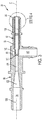
FIG. 3 is a cross section of a jet pump of the fuel transfer system; and -
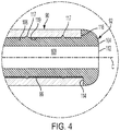
FIG. 4 is an enlarged, partial, cross section of the jet pump taken from circle 4 ofFIG. 3 . - Referring now to the Figures, where the invention will be described with reference to specific embodiments, without limiting same, a fuel storage and
delivery system 20 is illustrated inFIG. 1 , and may be utilized to storefuel 22 in a transport vehicle (not shown) and deliver the fuel to acombustion engine 24 of the vehicle. The fuel storage anddelivery system 20 includes a partitioned tank 26 (e.g., saddle tank) for storing thefuel 22, and afuel transfer system 28 adapted to deliver thefuel 22 to thecombustion engine 24. - The
partitioned tank 26 may include boundaries that define afirst chamber 30 and asecond chamber 32 separated by apartition 34 of the tank. In one embodiment, thefirst chamber 30 may be a primary chamber and thesecond chamber 32 may be an auxiliary chamber in direct fluid communication with the primary chamber above thepartition 34. Thefuel 22 may be stored in thetank 26 at substantially atmospheric pressure. In another embodiment, thepartitioned tank 26 may be two separate tanks, or compartments, in fluid communication with one another via at least one conduit (not shown). - Referring to
FIGS. 1 and2 , thefuel transfer system 28 of the fuel storage anddelivery system 20 may include afuel pump assembly 36, a fueljet pump device 38, ahigh pressure conduit 40, and a relativelylow pressure conduit 42. Thefuel pump assembly 36 may be located in the first, or primary,chamber 30, and is constructed to draw fuel from bothchambers combustion engine 24 via asupply conduit 44. - The
fuel pump assembly 36 of thefuel transfer system 28 may include asupport structure 46 that may generally include a fuel reservoir 68, at least one fuel pump (i.e., two illustrated inFIG. 2 as 48, 50), at least one check valve (i.e. two illustrated inFIG. 2 as 52, 54), apressure relief valve 56, an anti-siphon valve 58, a first, or primary, primary jet pump device 60, astrainer 62, anumbrella valve 64. - The
support structure 46 of thefuel pump assembly 36 may generally include alid 70, support stanchions or members 72 (i.e., two illustrated inFIG. 1 ), and a housing 74 (seeFIG. 1 ). Thelid 70 is adapted to sealably cover an opening 76 communicating through a wall 78 (e.g., upper wall) of thetank 26. Thestanchions 72 extend between, and are connected to, thehousing 74 and thelid 70. In one embodiment, thestanchions 72 are elongated and extend substantially vertically, to generally place thehousing 74 proximate to a bottom wall 80 of thetank 26 that defines in-part thefirst chamber 30. Thehousing 74 is constructed to generally encapsulate and/or support thefuel pumps 48,50, thecheck valve 52, 54, thepressure relief valve 56, the anti-siphon valve 58, the primary jet pump device 60, thestrainer 62, theumbrella valve 64, and the fuel reservoir 68. In one embodiment, the reservoir 68 may be a unitary part of thehousing 74. - The
fuel pumps 48, 50 are of the mechanically driven type, and thus may include electric motors (not shown) to drive the pumps. The first pump 48 may be adapted to supply pressurized fuel to thesupply conduit 44, and the primary jet pump device 60. The high pressure fuel flowing to the primary jet pump device 60 facilitates the drawing of low pressure fuel by the primary jet pump device 60 from thefirst chamber 30. The low pressure fuel is then mixed with the incoming high pressure fuel from the first pump 48, and the primary jet pump device 60 then expels the mixed fuel at a low pressure into the reservoir 68. - The
second pump 50 is adapted to supply pressurized fuel to thesupply conduit 44 and the fueljet pump device 38. The fueljet pump device 38 is constructed to draw low pressure fuel from thesecond chamber 32, mix the low pressure fuel with the incoming high pressure fuel from thesecond pump 50, and expel the mixed fuel at a low pressure into the reservoir 68. In one embodiment, the mixed fuel from eitherjet pump devices 60, 38 may be at about atmospheric pressure. - Each
fuel pump 48, 50 includesrespective outlets 82, 84 (i.e., outlet conduits) andrespective inlets 86, 88 (i.e., inlet conduits). Eachoutlet supply conduit 44, and eachinlet 86, 88 is in fluid communication with thestrainer 62. Thestrainer 62 is constructed to draw fuel from the reservoir 68, and thus provide filtered fuel to bothpumps 48, 50. - The
check valves 52, 54 are located atrespective outlets respective pump 48, 50, and are adapted to prevent the backflow of fuel through the pumps. Thepressure relief valve 56 is in fluid communication with thesupply conduit 44, and is adapted to expel fuel from thesupply conduit 44 and, in one example, back into the reservoir 68 upon overpressure conditions. Theumbrella valve 64 communicates through a bottom portion of the reservoir 68, and facilitates level control of fuel within the reservoir 68. - The primary jet pump device 60 receives high pressure fuel from pump 48 via a
high pressure conduit 75 that extends between the outlet 82 (i.e., upstream of the check valve 52) and the primary jet pump device 60. The anti-siphon valve 58 may be located in the high pressure conduit 75 (i.e., interposes), and is adapted to prevent siphoning of fuel from thefirst chamber 30, back-flowing through the primary jet pump device 60, and back-flowing through the pump 48 when the pump 48 is idle. - Referring to
FIGS. 2 and3 , the fueljet pump device 38 includes abody 90 that may be a unitary body, and aninsert 92 that may be tubular and interchangeable. Thebody 90 defines amixing passage 94, acavity 96, anintersection 98, and alow pressure passage 100. The mixingpassage 94, thecavity 96, and thelow pressure passage 100 are in fluid communication with one another generally at theintersection 98. In one embodiment, the mixingpassage 94 and thecavity 96 extend along, and are centered to, a common centerline C. Theintersection 98 is axially located between the mixingpassage 94 and thecavity 96. - Referring to
FIG. 3 , when the fueljet pump device 38 is assembled, theinsert 92 is substantially located in thecavity 96, and sealably seats against thebody 90. In one embodiment, theinsert 92 includesopposite end portions end portions high pressure passage 108. Thehigh pressure passage 108 is in fluid communication with theintersection 98 via a calibratedorifice 110 defined by theend portion 102 and centered to the centerline C. Theend portion 102 may be in, or proximate to, theintersection 98. - The
end portion 104 may be, or may include, an enlarged head that projects radially outward from the mid-portion 106. Theend portion 104 may be annular in shape, and radially inwardly defines an inlet port 112 in fluid communication between thehigh pressure passage 108 and thehigh pressure conduit 40. In one example, theend portion 104 carries astop surface 114 that faces axially toward theend portion 102, and may be annular in shape. Thecavity 96 communicates through thebody 90 at an end that carries astop face 116 that faces axially, opposes thestop surface 114, may be annular in shape, and may be centered to centerline C. When the fueljet pump device 38 is assembled, thestop surface 114 is in contact with thestop face 116, which facilitates placement (i.e., axial indexing) of thecalibration orifice 110 in theintersection 98. - The mid-portion 106 of the
tubular insert 92 may include at least one circumferentially continuous barb 117 (i.e., two illustrate inFIG. 4 ) spaced axially apart from one-another. Eachbarb 117 is in biased radial contact with a circumferentiallycontinuous seat 119 of thebody 90 that defines, at least in-part, thecavity 96. As illustrated inFIG. 4 , theseat 119 faces radially inward, is cylindrical, and substantially defines thecavity 96. - The mixing
passage 94 defined by thebody 90 may include a two tubular, or cylindrical,segments venturi segment 122. Thecylindrical segment 118 includes a diameter that is less than a diameter ofcylindrical segment 120, and communicates axially between theintersection 98 and theventuri segment 122. Thecylindrical segment 120 communicates through thebody 90, and between theventuri segment 122 and thelow pressure conduit 42. - The mixing
passage 94 and thecavity 96 may be substantially aligned axially and co-extend axially along the centerline C. Thelow pressure passage 100 may be generally normal to themixing passage 94. In one embodiment, thebody 90 and theinsert 92 are made of the same material, and both may be made of plastic. Theinsert 92 may further be interchangeable with other inserts having varying sized orifices. Theideal insert 92 may then be chosen to meet specific fluid dynamics of anyparticular delivery system 20. - It is contemplated and understood that the
insert 92 may not generally be tubular, and instead may be disc-shaped with a centrally located orifice. In this example, an axially leading surface of the disc may contact an axial face of thebody 90. That is, the disc-like insert 92 may seat within a counter-bore in the body. - It is further contemplated and understood that design attributes of the fuel
jet pump device 38 may be applied to the primary jet pump device 60. - In operation of the fuel
jet pump device 38, high pressure fuel produced by thepump 50, flows through thehigh pressure conduit 40, axially through thehigh pressure passage 108, through thecalibration orifice 110, and generally into theintersection 98 immediately adjacent to thesegment 118 of the mixingpassage 94. The high pressure flow through thecalibration orifice 110 causes thelow pressure passage 100 to draw fuel from thesecond chamber 32. This low pressure fuel flows through thelow pressure passage 100, through at least a portion of theintersection 98 and into thesegment 118 of the mixingpassage 94. The high and low pressure fuel is then mixed and reduced in pressure as it flows through thesegment 118, through theventuri segment 122, through thesegment 120, and into thelow pressure conduit 42. Thelow pressure conduit 42 may then deliver the fuel to the reservoir 68 infirst chamber 30. - Advantage and benefits of the present disclosure include: a reduction in the amount of critical high pressure assembly interfaces within the jet pump device, a flexible jet pump design that is easily adaptable for saddle tank application which traditionally demand high performance transfer systems, a self-centered plastic molded
insert 92 with a calibratedorifice 110 and indexing features for proper position of the orifice, a reduced amount of components from more traditional designs, and a reduced likelihood of burrs and machined defects that more negatively impact system performance. - While the invention has been described in detail in connection with only a limited number of embodiments, it should be readily understood that the invention is not limited to such disclosed embodiments. Rather, the invention can be modified to incorporate any number of variations, alterations, substitutions or equivalent arrangements not heretofore described, but which are commensurate with the spirit and scope of the invention. Additionally, while various embodiments of the invention have been described, it is to be understood that aspects of the invention may include only some of the described embodiments. Accordingly, the invention is not to be seen as limited by the foregoing description.
Claims (19)
- A fuel system (28) adapted to be utilized in a partitioned fuel tank (26) that defines a first chamber (30) and a second chamber (32), the fuel system (28) comprising:a fuel pump assembly (36) adapted to be disposed in the first chamber (30), the fuel pump assembly (36) including a motorized fuel pump (48);a fuel jet pump device (38) adapted to be disposed in the second chamber (32) and defining a low pressure passage (100) adapted to draw fuel (22) from the second chamber (32), a high pressure passage (108), and a mixing passage (94) adapted to receive and mix fuel (22) flowing from the low and high pressure passages (100,108);a high pressure conduit (40) adapted to extend between the first and second chambers (30,32), and in fluid communication between an outlet (82) of the fuel pump (48) and the high pressure passage (108); anda low pressure conduit (42) adapted to extend between the first and second chambers (30,32), and in fluid communication between the mixing passage (94) and the first chamber (30).
- The fuel system (28) set forth in claim 1, wherein the fuel jet pump device (38) defines a calibrated orifice (110) and an intersection (98), the calibrated orifice (110) being in fluid communication between the high pressure passage (108) and the intersection (98), and the intersection (98) adapted to receive fuel (22) from the low pressure passage (100) and the calibrated orifice (110) and expel fuel (22) into the mixing passage (94).
- The fuel system (28) set forth in claims 1 and 2, wherein the fuel jet pump device (38) includes a body (90) that defines the mixing passage (94), the low pressure passage (100), the intersection (98), and a cavity (96) in communication with the intersection (98), and includes a tubular insert (92) disposed in the cavity (96) and seated to the body (90), the tubular insert (92) defining the calibrated orifice (110) and the high pressure passage (108).
- The fuel system (28) set forth in all previous claims, wherein the body (90) defines a venturi (122) as part of the mixing passage (94).
- The fuel system (28) set forth in all previous claims, wherein the cavity (96) and the high pressure passage (108) are substantially aligned axially and co-extend axially along a centerline, and the body (90) includes a stop face (116) facing axially and in contact with an axially opposing stop surface (114) of the tubular insert (92).
- The fuel system (28) set forth in all previous claims, wherein the tubular insert (92) includes opposite first and second end portions (102,104) and a mid-portion (106) extending axially between the first and second end portions (102,104), the mid-portion (106) defining the high pressure passage (108), the first end portion (102) being located at the intersection (98) and defining the calibrated orifice (110), the second end portion (104) including an enlarged head projecting radially outward from the mid-portion (106) and defining an inlet port (112) in fluid communication with the high pressure passage (108), the enlarged head including the stop surface (114).
- The fuel system (28) set forth in all previous claims, wherein the body (90) and the tubular insert (92) are made of plastic.
- The fuel system (28) set forth in all previous claims, wherein the stop face (116) and the stop surface (114) are annular in shape and centered about the centerline.
- The fuel system (28) set forth in all previous claims, wherein the fuel pump assembly (36) includes a structure that defines a reservoir (68), and the low pressure conduit (42) is adapted to flow fuel (22) from the second chamber (32) and into the reservoir (68).
- The fuel system (28) set forth in all previous claims, wherein the fuel pump (48) is adapted to draw fuel (22) from the reservoir (68).
- A fuel jet pump assembly (38) comprising:a body (90) defining a mixing passage (94), a low pressure passage (100), and a cavity (96) in communication with one another at an intersection (98), the body (90) including a stop face (116); anda tubular insert (92) including opposite first and second end portions (102,104) and a mid-portion (106), the mid-portion (106) defining a high pressure passage (108) extending along a centerline, extending axially between the first and second end portions (102,104), and disposed in the cavity (96), the first end portion (102) located at the intersection (98) and defining a calibrated orifice (110) in fluid communication with the low pressure passage (100), the high pressure passage (108) and the mixing passage (94), the second end portion (104) including an enlarged head projecting radially outward from the mid-portion (106) and defining an inlet port (112) in fluid communication with the high pressure passage (108), the enlarged head including a stop surface (114) in axial contact with the stop face (116).
- The fuel jet pump assembly (38) set forth in claim 11, wherein the body (90) and the tubular insert (92) are made of plastic.
- The fuel jet pump assembly (38) set forth in claims 11 and 12, wherein the stop face (116) and the stop surface (114) are annular in shape and centered to the centerline.
- The fuel jet pump assembly (38) set forth in claims 11 to 13, wherein the calibrated orifice (110) is centered to the centerline.
- The fuel jet pump assembly (38) set forth in claims 11 to 14, wherein the tubular insert (92) is interchangeable.
- The fuel jet pump assembly (38) set forth in claims 11 to 15, wherein the high pressure passage (108) flows fuel (22) from the inlet port (112) and through the calibrated orifice (110), the low pressure passage (100) flows fuel (22) into the intersection (98), and the mixing passage (94) flows fuel (22) emitted from the intersection (98).
- The fuel jet pump assembly (38) set forth in claims 11 to 16, wherein the mixing passage (94) extends along the centerline, and includes a venturi segment (122) extending axially.
- The fuel jet pump assembly (38) set forth in claims 11 to 17, wherein the mixing passage (94) includes a tubular segment (118) communicating axially between the intersection (98) and the venturi segment (122).
- The fuel jet pump assembly (38) set forth in claims 11 to 18, wherein the mid-portion (106) includes a circumferentially continuous barb (117) in biased radial contact with a circumferentially continuous seat (119) of the body (90) that defines at least in-part the cavity (96).
Applications Claiming Priority (1)
| Application Number | Priority Date | Filing Date | Title |
|---|---|---|---|
| US16/276,773 US10662911B1 (en) | 2019-02-15 | 2019-02-15 | Fuel transfer system including a fuel jet pump device and utilized in a partitioned fuel tank |
Publications (3)
| Publication Number | Publication Date |
|---|---|
| EP3696399A2 true EP3696399A2 (en) | 2020-08-19 |
| EP3696399A3 EP3696399A3 (en) | 2020-11-11 |
| EP3696399B1 EP3696399B1 (en) | 2025-04-30 |
Family
ID=69500560
Family Applications (1)
| Application Number | Title | Priority Date | Filing Date |
|---|---|---|---|
| EP20155555.4A Active EP3696399B1 (en) | 2019-02-15 | 2020-02-05 | A fuel transfer system including a fuel jet pump device and utilized in a partitioned fuel tank |
Country Status (2)
| Country | Link |
|---|---|
| US (1) | US10662911B1 (en) |
| EP (1) | EP3696399B1 (en) |
Families Citing this family (3)
| Publication number | Priority date | Publication date | Assignee | Title |
|---|---|---|---|---|
| US10975814B1 (en) * | 2018-04-09 | 2021-04-13 | Aeromotive, Inc. | Apparatus and method for modifying a fuel tank to accept an in-tank fuel pump |
| US20250314226A1 (en) * | 2024-04-08 | 2025-10-09 | Hobomoped LLC | Fuel pump assembly for fuel injected motorcycles |
| US12473192B1 (en) * | 2025-09-03 | 2025-11-18 | Zhongshan Yulite Technology Co., LTD | Anti-siphonage and anti-overflow fuel pump structure |
Family Cites Families (30)
| Publication number | Priority date | Publication date | Assignee | Title |
|---|---|---|---|---|
| DE4238040A1 (en) * | 1992-11-11 | 1994-05-19 | Vdo Schindling | Suction jet pump for pumping fuel |
| US5716006A (en) * | 1996-04-15 | 1998-02-10 | Lott; William Gerald | Jet pump having an improved nozzle and a diffuser |
| DE19736088A1 (en) | 1997-08-20 | 1999-02-25 | Bosch Gmbh Robert | Fuel pump priming system for internal combustion engine |
| DE19750036C2 (en) | 1997-11-12 | 1999-09-02 | Mannesmann Vdo Ag | Fuel delivery device |
| EP0979939B1 (en) | 1998-08-10 | 2006-10-04 | Siemens Aktiengesellschaft | Fuel supply system |
| US6155793A (en) * | 1999-06-08 | 2000-12-05 | Walbro Corporation | Recessed fuel pump module |
| FR2798164B1 (en) * | 1999-09-07 | 2001-11-23 | Marwal Systems | FUEL PUMP DEVICE FOR A MOTOR VEHICLE TANK |
| US6505644B2 (en) | 2000-06-09 | 2003-01-14 | Delphi Technologies, Inc. | Dual barrel jet fuel pump assembly for a fuel tank |
| US6405717B1 (en) * | 2000-08-01 | 2002-06-18 | Delphi Technologies, Inc. | Fuel pump module assembly |
| DE10229801A1 (en) * | 2002-07-03 | 2004-01-22 | Ti Automotive (Neuss) Gmbh | eductor |
| US6951131B2 (en) | 2002-09-06 | 2005-10-04 | Delphi Technologies, Inc. | Fuel level indication assembly |
| US6966302B2 (en) * | 2004-01-26 | 2005-11-22 | Ti Group Automotive Systems, L.L.C. | Fuel system and flow control valve |
| US7182869B2 (en) * | 2004-10-07 | 2007-02-27 | Ti Group Automotive Systems, L.L.C. | Fuel filter arrangement |
| DE102005008380A1 (en) * | 2005-02-23 | 2006-08-31 | Siemens Ag | Fuel supply for motor vehicle, has electrically propelled transfer pump arranged within fuel tank, where pressure side of transfer pump is connected with nozzles of ejector pumps, and transfers pump is discontinuously switched |
| US7353807B2 (en) * | 2005-04-19 | 2008-04-08 | Ti Group Automotive Systems, L.L.C. | Jet pump assembly of a fuel system for a combustion engine |
| US7069913B1 (en) * | 2005-08-18 | 2006-07-04 | Ti Group Automotive Systems, L.L.C. | Fuel delivery system for a combustion engine |
| CN100436821C (en) * | 2005-12-29 | 2008-11-26 | 阳江市新力工业有限公司 | A stamping welding deep well pump |
| US7617814B2 (en) * | 2008-03-06 | 2009-11-17 | Synerject, Llc | Fuel pump module having a direct mounted jet pump and methods of assembly |
| JP4893817B2 (en) * | 2009-12-23 | 2012-03-07 | 株式会社デンソー | Fuel supply device |
| DE102010062075A1 (en) * | 2010-11-26 | 2012-05-31 | Robert Bosch Gmbh | Tank arrangement with mechanical pressure regulator and vehicle |
| DE102011075230A1 (en) * | 2011-05-04 | 2012-11-08 | Robert Bosch Gmbh | Jet pump for conveying fuel |
| KR101075794B1 (en) | 2011-08-30 | 2011-10-24 | 주식회사 코아비스 | Fuel pump module |
| US8622715B1 (en) * | 2011-12-21 | 2014-01-07 | Compatible Components Corporation | Twin turbine asymmetrical nozzle and jet pump incorporating such nozzle |
| US20140314591A1 (en) | 2013-04-18 | 2014-10-23 | Delphi Technologies, Inc. | Fluid pump |
| DE102014207221A1 (en) | 2014-04-15 | 2015-10-15 | Robert Bosch Gmbh | Fuel delivery device for a saddle tank |
| KR101575495B1 (en) * | 2014-06-20 | 2015-12-08 | 현대자동차주식회사 | Fuel feeding system for vehicle |
| US9745931B2 (en) | 2015-12-01 | 2017-08-29 | Delphi Technologies, Inc. | Fuel system with a fuel pump control module and a heat sink |
| DE102016206616A1 (en) * | 2016-04-19 | 2017-10-19 | Elringklinger Ag | Ejector device and combination of a cylinder head cover and an ejector device |
| US10495039B2 (en) | 2017-03-30 | 2019-12-03 | Delphi Technologies Ip Limited | Fuel system having a jet pump |
| EP3403864B1 (en) * | 2017-05-18 | 2020-01-08 | Ningbo Geely Automobile Research & Development Co., Ltd. | A fuel ejector assembly for a vehicle |
-
2019
- 2019-02-15 US US16/276,773 patent/US10662911B1/en active Active
-
2020
- 2020-02-05 EP EP20155555.4A patent/EP3696399B1/en active Active
Also Published As
| Publication number | Publication date |
|---|---|
| EP3696399B1 (en) | 2025-04-30 |
| US10662911B1 (en) | 2020-05-26 |
| EP3696399A3 (en) | 2020-11-11 |
Similar Documents
| Publication | Publication Date | Title |
|---|---|---|
| EP3696399B1 (en) | A fuel transfer system including a fuel jet pump device and utilized in a partitioned fuel tank | |
| US7117856B2 (en) | Fuel delivery systems | |
| US6276342B1 (en) | Fuel supply system | |
| US7069913B1 (en) | Fuel delivery system for a combustion engine | |
| US8459960B2 (en) | Jet pump assembly | |
| WO1995030831A1 (en) | Non-return fuel system with fuel pressure vacuum response | |
| CN109812361B (en) | Vehicle fuel pump module including improved jet pump assembly | |
| US8789512B2 (en) | Fluid pressure regulating device and fuel supply system using same | |
| US5595160A (en) | Fuel supply system and delivery pipe for use in same | |
| JP2007239682A (en) | Fuel supply device | |
| CN109812362B (en) | Vehicle fuel pump module including improved jet pump assembly | |
| EP3591212A1 (en) | Fuel system having a jet pump | |
| US7051716B2 (en) | Fuel tank | |
| US7909023B2 (en) | Fuel supply systems | |
| US7473069B2 (en) | Fuel pump for a fuel tank | |
| US11434931B2 (en) | Fuel system having a valve upstream of a jet pump | |
| US3181468A (en) | Fuel supply system | |
| CN111868372B (en) | Fuel pump assembly with split flow | |
| JP4800331B2 (en) | Fuel pump and fuel supply device | |
| US7222609B2 (en) | Fuel supply system | |
| JP3757432B2 (en) | Fuel supply device and delivery pipe | |
| EP4051407B1 (en) | A filter cartridge for a liquid such as fuel, the upper end plate of which including an automatic degassing valve | |
| JP3167104B2 (en) | Fuel supply unit | |
| US7950372B2 (en) | By-pass regulator assembly for dual ERFS/MRFS fuel pump module | |
| JPH0339199B2 (en) |
Legal Events
| Date | Code | Title | Description |
|---|---|---|---|
| PUAI | Public reference made under article 153(3) epc to a published international application that has entered the european phase |
Free format text: ORIGINAL CODE: 0009012 |
|
| STAA | Information on the status of an ep patent application or granted ep patent |
Free format text: STATUS: THE APPLICATION HAS BEEN PUBLISHED |
|
| AK | Designated contracting states |
Kind code of ref document: A2 Designated state(s): AL AT BE BG CH CY CZ DE DK EE ES FI FR GB GR HR HU IE IS IT LI LT LU LV MC MK MT NL NO PL PT RO RS SE SI SK SM TR |
|
| AX | Request for extension of the european patent |
Extension state: BA ME |
|
| PUAL | Search report despatched |
Free format text: ORIGINAL CODE: 0009013 |
|
| AK | Designated contracting states |
Kind code of ref document: A3 Designated state(s): AL AT BE BG CH CY CZ DE DK EE ES FI FR GB GR HR HU IE IS IT LI LT LU LV MC MK MT NL NO PL PT RO RS SE SI SK SM TR |
|
| AX | Request for extension of the european patent |
Extension state: BA ME |
|
| RIC1 | Information provided on ipc code assigned before grant |
Ipc: F02M 37/02 20060101ALI20201002BHEP Ipc: F04B 23/04 20060101ALI20201002BHEP Ipc: F04F 5/10 20060101ALI20201002BHEP Ipc: F02M 37/18 20060101ALI20201002BHEP Ipc: F02M 37/04 20060101ALI20201002BHEP Ipc: F02M 37/00 20060101AFI20201002BHEP Ipc: F02M 37/10 20060101ALI20201002BHEP Ipc: F04F 5/46 20060101ALI20201002BHEP |
|
| STAA | Information on the status of an ep patent application or granted ep patent |
Free format text: STATUS: REQUEST FOR EXAMINATION WAS MADE |
|
| 17P | Request for examination filed |
Effective date: 20210511 |
|
| RBV | Designated contracting states (corrected) |
Designated state(s): AL AT BE BG CH CY CZ DE DK EE ES FI FR GB GR HR HU IE IS IT LI LT LU LV MC MK MT NL NO PL PT RO RS SE SI SK SM TR |
|
| STAA | Information on the status of an ep patent application or granted ep patent |
Free format text: STATUS: EXAMINATION IS IN PROGRESS |
|
| 17Q | First examination report despatched |
Effective date: 20220211 |
|
| P01 | Opt-out of the competence of the unified patent court (upc) registered |
Effective date: 20230327 |
|
| RAP1 | Party data changed (applicant data changed or rights of an application transferred) |
Owner name: PHINIA DELPHI LUXEMBOURG SARL |
|
| GRAP | Despatch of communication of intention to grant a patent |
Free format text: ORIGINAL CODE: EPIDOSNIGR1 |
|
| STAA | Information on the status of an ep patent application or granted ep patent |
Free format text: STATUS: GRANT OF PATENT IS INTENDED |
|
| INTG | Intention to grant announced |
Effective date: 20241218 |
|
| GRAS | Grant fee paid |
Free format text: ORIGINAL CODE: EPIDOSNIGR3 |
|
| GRAA | (expected) grant |
Free format text: ORIGINAL CODE: 0009210 |
|
| STAA | Information on the status of an ep patent application or granted ep patent |
Free format text: STATUS: THE PATENT HAS BEEN GRANTED |
|
| AK | Designated contracting states |
Kind code of ref document: B1 Designated state(s): AL AT BE BG CH CY CZ DE DK EE ES FI FR GB GR HR HU IE IS IT LI LT LU LV MC MK MT NL NO PL PT RO RS SE SI SK SM TR |
|
| REG | Reference to a national code |
Ref country code: CH Ref legal event code: EP Ref country code: GB Ref legal event code: FG4D |
|
| REG | Reference to a national code |
Ref country code: DE Ref legal event code: R096 Ref document number: 602020050265 Country of ref document: DE |
|
| REG | Reference to a national code |
Ref country code: IE Ref legal event code: FG4D |
|
| REG | Reference to a national code |
Ref country code: NL Ref legal event code: MP Effective date: 20250430 |
|
| REG | Reference to a national code |
Ref country code: AT Ref legal event code: MK05 Ref document number: 1790218 Country of ref document: AT Kind code of ref document: T Effective date: 20250430 |
|
| PG25 | Lapsed in a contracting state [announced via postgrant information from national office to epo] |
Ref country code: FI Free format text: LAPSE BECAUSE OF FAILURE TO SUBMIT A TRANSLATION OF THE DESCRIPTION OR TO PAY THE FEE WITHIN THE PRESCRIBED TIME-LIMIT Effective date: 20250430 Ref country code: ES Free format text: LAPSE BECAUSE OF FAILURE TO SUBMIT A TRANSLATION OF THE DESCRIPTION OR TO PAY THE FEE WITHIN THE PRESCRIBED TIME-LIMIT Effective date: 20250430 Ref country code: PT Free format text: LAPSE BECAUSE OF FAILURE TO SUBMIT A TRANSLATION OF THE DESCRIPTION OR TO PAY THE FEE WITHIN THE PRESCRIBED TIME-LIMIT Effective date: 20250901 |
|
| REG | Reference to a national code |
Ref country code: LT Ref legal event code: MG9D |
|
| PG25 | Lapsed in a contracting state [announced via postgrant information from national office to epo] |
Ref country code: GR Free format text: LAPSE BECAUSE OF FAILURE TO SUBMIT A TRANSLATION OF THE DESCRIPTION OR TO PAY THE FEE WITHIN THE PRESCRIBED TIME-LIMIT Effective date: 20250731 Ref country code: NO Free format text: LAPSE BECAUSE OF FAILURE TO SUBMIT A TRANSLATION OF THE DESCRIPTION OR TO PAY THE FEE WITHIN THE PRESCRIBED TIME-LIMIT Effective date: 20250730 |
|
| PG25 | Lapsed in a contracting state [announced via postgrant information from national office to epo] |
Ref country code: PL Free format text: LAPSE BECAUSE OF FAILURE TO SUBMIT A TRANSLATION OF THE DESCRIPTION OR TO PAY THE FEE WITHIN THE PRESCRIBED TIME-LIMIT Effective date: 20250430 Ref country code: NL Free format text: LAPSE BECAUSE OF FAILURE TO SUBMIT A TRANSLATION OF THE DESCRIPTION OR TO PAY THE FEE WITHIN THE PRESCRIBED TIME-LIMIT Effective date: 20250430 |
|
| PG25 | Lapsed in a contracting state [announced via postgrant information from national office to epo] |
Ref country code: BG Free format text: LAPSE BECAUSE OF FAILURE TO SUBMIT A TRANSLATION OF THE DESCRIPTION OR TO PAY THE FEE WITHIN THE PRESCRIBED TIME-LIMIT Effective date: 20250430 |
|
| PG25 | Lapsed in a contracting state [announced via postgrant information from national office to epo] |
Ref country code: HR Free format text: LAPSE BECAUSE OF FAILURE TO SUBMIT A TRANSLATION OF THE DESCRIPTION OR TO PAY THE FEE WITHIN THE PRESCRIBED TIME-LIMIT Effective date: 20250430 |
|
| PG25 | Lapsed in a contracting state [announced via postgrant information from national office to epo] |
Ref country code: AT Free format text: LAPSE BECAUSE OF FAILURE TO SUBMIT A TRANSLATION OF THE DESCRIPTION OR TO PAY THE FEE WITHIN THE PRESCRIBED TIME-LIMIT Effective date: 20250430 |
|
| PG25 | Lapsed in a contracting state [announced via postgrant information from national office to epo] |
Ref country code: RS Free format text: LAPSE BECAUSE OF FAILURE TO SUBMIT A TRANSLATION OF THE DESCRIPTION OR TO PAY THE FEE WITHIN THE PRESCRIBED TIME-LIMIT Effective date: 20250731 |
|
| PG25 | Lapsed in a contracting state [announced via postgrant information from national office to epo] |
Ref country code: IS Free format text: LAPSE BECAUSE OF FAILURE TO SUBMIT A TRANSLATION OF THE DESCRIPTION OR TO PAY THE FEE WITHIN THE PRESCRIBED TIME-LIMIT Effective date: 20250830 |
|
| PG25 | Lapsed in a contracting state [announced via postgrant information from national office to epo] |
Ref country code: LV Free format text: LAPSE BECAUSE OF FAILURE TO SUBMIT A TRANSLATION OF THE DESCRIPTION OR TO PAY THE FEE WITHIN THE PRESCRIBED TIME-LIMIT Effective date: 20250430 |
|
| PG25 | Lapsed in a contracting state [announced via postgrant information from national office to epo] |
Ref country code: SM Free format text: LAPSE BECAUSE OF FAILURE TO SUBMIT A TRANSLATION OF THE DESCRIPTION OR TO PAY THE FEE WITHIN THE PRESCRIBED TIME-LIMIT Effective date: 20250430 Ref country code: DK Free format text: LAPSE BECAUSE OF FAILURE TO SUBMIT A TRANSLATION OF THE DESCRIPTION OR TO PAY THE FEE WITHIN THE PRESCRIBED TIME-LIMIT Effective date: 20250430 |
|
| PG25 | Lapsed in a contracting state [announced via postgrant information from national office to epo] |
Ref country code: CZ Free format text: LAPSE BECAUSE OF FAILURE TO SUBMIT A TRANSLATION OF THE DESCRIPTION OR TO PAY THE FEE WITHIN THE PRESCRIBED TIME-LIMIT Effective date: 20250430 |
|
| PG25 | Lapsed in a contracting state [announced via postgrant information from national office to epo] |
Ref country code: EE Free format text: LAPSE BECAUSE OF FAILURE TO SUBMIT A TRANSLATION OF THE DESCRIPTION OR TO PAY THE FEE WITHIN THE PRESCRIBED TIME-LIMIT Effective date: 20250430 |
|
| PG25 | Lapsed in a contracting state [announced via postgrant information from national office to epo] |
Ref country code: RO Free format text: LAPSE BECAUSE OF FAILURE TO SUBMIT A TRANSLATION OF THE DESCRIPTION OR TO PAY THE FEE WITHIN THE PRESCRIBED TIME-LIMIT Effective date: 20250430 Ref country code: SK Free format text: LAPSE BECAUSE OF FAILURE TO SUBMIT A TRANSLATION OF THE DESCRIPTION OR TO PAY THE FEE WITHIN THE PRESCRIBED TIME-LIMIT Effective date: 20250430 |
|
| PG25 | Lapsed in a contracting state [announced via postgrant information from national office to epo] |
Ref country code: IT Free format text: LAPSE BECAUSE OF FAILURE TO SUBMIT A TRANSLATION OF THE DESCRIPTION OR TO PAY THE FEE WITHIN THE PRESCRIBED TIME-LIMIT Effective date: 20250430 |
|
| REG | Reference to a national code |
Ref country code: DE Ref legal event code: R097 Ref document number: 602020050265 Country of ref document: DE |
|
| PLBE | No opposition filed within time limit |
Free format text: ORIGINAL CODE: 0009261 |
|
| STAA | Information on the status of an ep patent application or granted ep patent |
Free format text: STATUS: NO OPPOSITION FILED WITHIN TIME LIMIT |
|
| REG | Reference to a national code |
Ref country code: CH Ref legal event code: L10 Free format text: ST27 STATUS EVENT CODE: U-0-0-L10-L00 (AS PROVIDED BY THE NATIONAL OFFICE) Effective date: 20260311 |
|
| 26N | No opposition filed |
Effective date: 20260202 |