EP3696130A1 - Elevator entryway with magnetic guidance for controlling door panel motion - Google Patents
Elevator entryway with magnetic guidance for controlling door panel motion Download PDFInfo
- Publication number
- EP3696130A1 EP3696130A1 EP19217480.3A EP19217480A EP3696130A1 EP 3696130 A1 EP3696130 A1 EP 3696130A1 EP 19217480 A EP19217480 A EP 19217480A EP 3696130 A1 EP3696130 A1 EP 3696130A1
- Authority
- EP
- European Patent Office
- Prior art keywords
- magnet
- sill
- axis
- door
- roller
- Prior art date
- Legal status (The legal status is an assumption and is not a legal conclusion. Google has not performed a legal analysis and makes no representation as to the accuracy of the status listed.)
- Granted
Links
Images
Classifications
-
- B—PERFORMING OPERATIONS; TRANSPORTING
- B66—HOISTING; LIFTING; HAULING
- B66B—ELEVATORS; ESCALATORS OR MOVING WALKWAYS
- B66B13/00—Doors, gates, or other apparatus controlling access to, or exit from, cages or lift well landings
- B66B13/02—Door or gate operation
- B66B13/14—Control systems or devices
-
- B—PERFORMING OPERATIONS; TRANSPORTING
- B66—HOISTING; LIFTING; HAULING
- B66B—ELEVATORS; ESCALATORS OR MOVING WALKWAYS
- B66B1/00—Control systems of elevators in general
- B66B1/34—Details, e.g. call counting devices, data transmission from car to control system, devices giving information to the control system
- B66B1/3415—Control system configuration and the data transmission or communication within the control system
- B66B1/3423—Control system configuration, i.e. lay-out
-
- B—PERFORMING OPERATIONS; TRANSPORTING
- B66—HOISTING; LIFTING; HAULING
- B66B—ELEVATORS; ESCALATORS OR MOVING WALKWAYS
- B66B1/00—Control systems of elevators in general
- B66B1/34—Details, e.g. call counting devices, data transmission from car to control system, devices giving information to the control system
- B66B1/3415—Control system configuration and the data transmission or communication within the control system
- B66B1/3446—Data transmission or communication within the control system
-
- B—PERFORMING OPERATIONS; TRANSPORTING
- B66—HOISTING; LIFTING; HAULING
- B66B—ELEVATORS; ESCALATORS OR MOVING WALKWAYS
- B66B13/00—Doors, gates, or other apparatus controlling access to, or exit from, cages or lift well landings
- B66B13/02—Door or gate operation
- B66B13/06—Door or gate operation of sliding doors
- B66B13/08—Door or gate operation of sliding doors guided for horizontal movement
-
- B—PERFORMING OPERATIONS; TRANSPORTING
- B66—HOISTING; LIFTING; HAULING
- B66B—ELEVATORS; ESCALATORS OR MOVING WALKWAYS
- B66B13/00—Doors, gates, or other apparatus controlling access to, or exit from, cages or lift well landings
- B66B13/30—Constructional features of doors or gates
-
- B—PERFORMING OPERATIONS; TRANSPORTING
- B66—HOISTING; LIFTING; HAULING
- B66B—ELEVATORS; ESCALATORS OR MOVING WALKWAYS
- B66B13/00—Doors, gates, or other apparatus controlling access to, or exit from, cages or lift well landings
- B66B13/30—Constructional features of doors or gates
- B66B13/301—Details of door sills
-
- B—PERFORMING OPERATIONS; TRANSPORTING
- B66—HOISTING; LIFTING; HAULING
- B66B—ELEVATORS; ESCALATORS OR MOVING WALKWAYS
- B66B13/00—Doors, gates, or other apparatus controlling access to, or exit from, cages or lift well landings
- B66B13/30—Constructional features of doors or gates
- B66B13/303—Details of door panels
-
- B—PERFORMING OPERATIONS; TRANSPORTING
- B66—HOISTING; LIFTING; HAULING
- B66B—ELEVATORS; ESCALATORS OR MOVING WALKWAYS
- B66B5/00—Applications of checking, fault-correcting, or safety devices in elevators
- B66B5/0006—Monitoring devices or performance analysers
- B66B5/0018—Devices monitoring the operating condition of the elevator system
Definitions
- the embodiments herein relate to elevator systems and more specifically to an elevator entryway using magnetic guidance to control door panel motion.
- Sill located debris may be considered a leading cause of unscheduled elevator maintenance.
- Existing elevator designs may guide an elevator door by utilizing a combination of rollers and rails at a top level of the elevator door and a combination of a groove and groove guides (for example, protrusions) that are guided within the groove at a base of the door.
- the groove may be located in an elevator sill and may collect debris, which may be challenging to remove.
- an elevator system comprising: a door panel configured for moving along a first axis for opening and closing of the door panel at an entryway, the door panel comprising a door magnet, the entryway including a sill, the sill having a sill magnet, wherein the door magnet and the sill magnet are configured for forming a first magnetic pairing, and wherein the first magnetic pairing guides the door panel to move along the first axis and prevents the door panel from moving in a lateral direction with respect to the first axis.
- a top surface of the sill is without inset guide grooves.
- the door panel comprises a base and the door magnet is at or proximate the base.
- the sill includes a sill enclosure that is sealed, and the sill magnet is within the sill enclosure.
- the sill enclosure includes a track that extends along the first axis and the sill magnet is movable along the track for traveling in the first axis with the door magnet when the door is opening and closing.
- the sill magnet is movably supported on the track by at least one roller.
- the door magnet is a first set of magnets that comprises a first magnet and a second magnet spaced along the first axis by a first distance
- the sill magnet is a second set of magnets that comprises a third magnet and a fourth magnet that are spaced along the first axis by the first distance, whereby as the door panel moves along the first axis, the first magnet is aligned with the third magnet and the second magnet is aligned with the fourth magnet.
- the third magnet and the fourth magnet are spaced by a mechanical spacer that extend along the first axis.
- the track includes a pair of track rails, including a first track rail and a second track rail, the pair of track rails extending along the first axis and being spaced from each other in the lateral direction; and the third magnet and the fourth magnet each comprise: a first roller of the at least one roller, the first roller traveling on the first track rail; and a second roller of the at least one roller, the second roller traveling on the second track rail.
- first roller and the second roller are each a pair of rollers.
- a method of configuring an elevator system comprising: configuring a door panel for moving along a first axis for opening and closing of the door panel at an entryway, the door panel comprising a door magnet, wherein the entryway includes a sill, the sill includes a sill magnet, and configuring the door magnet and the sill magnet for forming a first magnetic pairing, wherein the first magnetic pairing guides the door panel to move along the first axis and prevents the door panel from moving in a lateral direction with respect to the first axis.
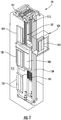
- FIG. 1 is a perspective view of an elevator system 101 including an elevator car 103, a counterweight 105, a tension member 107, a guide rail 109, a machine 111, a position reference system 113, and a controller 115.
- the elevator car 103 and counterweight 105 are connected to each other by the tension member 107.
- the tension member 107 may include or be configured as, for example, ropes, steel cables, and/or coated-steel belts.
- the counterweight 105 is configured to balance a load of the elevator car 103 and is configured to facilitate movement of the elevator car 103 concurrently and in an opposite direction with respect to the counterweight 105 within an elevator shaft 117 and along the guide rail 109.
- the tension member 107 engages the machine 111, which is part of an overhead structure of the elevator system 101.
- the machine 111 is configured to control movement between the elevator car 103 and the counterweight 105.
- the position reference system 113 may be mounted on a fixed part at the top of the elevator shaft 117, such as on a support or guide rail, and may be configured to provide position signals related to a position of the elevator car 103 within the elevator shaft 117. In other embodiments, the position reference system 113 may be directly mounted to a moving component of the machine 111, or may be located in other positions and/or configurations as known in the art.
- the position reference system 113 can be any device or mechanism for monitoring a position of an elevator car and/or counter weight, as known in the art.
- the position reference system 113 can be an encoder, sensor, or other system and can include velocity sensing, absolute position sensing, etc., as will be appreciated by those of skill in the art.
- the controller 115 is located, as shown, in a controller room 121 of the elevator shaft 117 and is configured to control the operation of the elevator system 101, and particularly the elevator car 103.
- the controller 115 may provide drive signals to the machine 111 to control the acceleration, deceleration, leveling, stopping, etc. of the elevator car 103.
- the controller 115 may also be configured to receive position signals from the position reference system 113 or any other desired position reference device.
- the elevator car 103 may stop at one or more landings 125 as controlled by the controller 115.
- the controller 115 can be located and/or configured in other locations or positions within the elevator system 101. In one embodiment, the controller may be located remotely or in the cloud.
- the machine 111 may include a motor or similar driving mechanism.
- the machine 111 is configured to include an electrically driven motor.
- the power supply for the motor may be any power source, including a power grid, which, in combination with other components, is supplied to the motor.
- the machine 111 may include a traction sheave that imparts force to tension member 107 to move the elevator car 103 within elevator shaft 117.
- FIG. 1 is merely a non-limiting example presented for illustrative and explanatory purposes.
- the system 200 includes a door panel 210 configured for moving along a first axis 220 for opening and closing of the door panel 210 at an entryway 230.
- the door panel 210 includes a door magnet 240.
- the door panel 210 as identified herein may be a bottom half of an elevator door, where a top half (not illustrated) is guided by typical means such as rollers/rails.
- the entryway 230 including a sill 250.
- the sill 250 has a sill magnet 260.
- the door magnet 240 and the sill magnet 260 may be configured for forming a first magnetic pairing.
- the first magnetic pairing guides the door panel 210 to move along the first axis 220 and prevents the door panel 210 from moving in a lateral direction with respect to the first axis 220.
- the first magnetic pairing prevents the door from swinging inwardly and outwardly with respect to the entryway 230, laterally with respect to the first axis 220, to thereby avoid interaction with passengers. Sizing and configuring of the magnets may provide for such restrictive motion.
- a top surface of the sill that faces a bottom of the door panel may without guide-tracks.
- the surface may without inset guide grooves so that it be a flat-planar surface or may contain surface indicia to enable walking traction. That is, the surface may exclude grooves associated with other door panel guide configurations.
- the first magnetic pairing may be passive. This prevents providing an additional electrical burden on the elevator system.
- platform structures 235 of the entryway 230 are non-ferrous metals to avoid biasing the magnets.
- the door panel 210 may include a base 270.
- the base 270 may be defined by a bottom portion of the door panel 210.
- the door magnet 240 may be disposed at or proximate the base 270.
- the sill 250 may include a sill enclosure 290 that is sealed.
- the sill magnet 260 may be disposed within the sill enclosure 290.
- the sill enclosure 290 may include a track 300 that extends along the first axis 220.
- the sill magnet 260 may be movable along the track 300 for traveling along the first axis 220 with the first magnet 240.
- the sill magnet 260 may be movably supported on the track 300 by at least one roller 310.
- the door magnet 240 may be a first set of magnets that comprises a first magnet 320 and a second magnet 330 spaced along the first axis 220 by a first distance.
- the sill magnet 260 may be a second set of magnets that comprises a third magnet 340 and a fourth magnet 350 that are spaced along the first axis 220 by the first distance. From this configuration, as the door panel 210 moves along the first axis 220, the first magnet 320 may be aligned with the third magnet 340 and the second magnet 330 may be aligned with the fourth magnet 350.
- the third magnet 340 and the fourth magnet 350 may be spaced by a mechanical spacer 360.
- the mechanical spacer 360 may extend along the first axis 220.
- the mechanical spacer 360 may be a frame structure such as a bar, a cylinder or other formed or machined member.
- the track 300 may include a pair of track rails, including a first track rail 370 and a second track rail 380.
- the pair of track rails 370, 380 may extend along the first axis and may be spaced from each other in the lateral direction.
- the third magnet 340 and the fourth magnet 350 each comprise a first roller 390 of the at least one roller 310 that that travels on the first track rail 370 and a second roller 400 of the at least one roller 310 that travels on the second track rail 380.
- the first roller 390 and the second roller 400 are each a pair of rollers.
- a spacing D1 between a bottom of the panel 210 and the sill 250 may be a few millimeters, such as three millimeters.
- a thickness of the sill 250 may be the same as D1.
- the sill 250 may be designed to accommodate such thickness without buckling under the weight of normal use.
- the sill 250 may be a reinforced and/or composite material.
- the thickness of the sill 250 may change between areas A1 where the magnets are directly below the sill 250 and, for example, areas A2 where the rollers are directly below the sill 250. That is, areas where the rollers are directly below the sill 250 may be thicker than areas magnets are directly below the sill 250.
- the above disclosed embodiments provide a plurality of sets of paired magnets including a first set of magnets within a door panel and a second set of magnets underneath the sill.
- the door may be guided along a travel path without the need of a groove.
- Magnet sets may be configured, for example, with magnetic strength characteristics that may prevent door movement out of a door sliding axis.
- the magnets are rare earth magnets such as neodymium. Magnetic attraction may be passive rather than requiring power to avoid affecting power requirements for the elevator system.
- electromagnets may be utilized. If electromagnets are used, such magnets may be used in either the door or sill of the assembly. Placing electromagnets in the sill may avoid providing power to the door panels. In addition, electrical cables for a sill electromagnet may be hidden behind a toe guard positioned behind the sill.
- magnets may be placed on rollers to enable traveling of the magnets in the door sliding axis.
- the rollers may be placed in enclosed track, thereby being insulated from debris.
- the sill magnets may be provided as a plurality of sets spaced along the door sliding axis and the door magnet may be provided as a plurality of sets spaced along the door sliding axis. Spacing between the plurality of sets of sill magnets may obtained, for example, by a mechanical connection between the plurality of sets of sill magnets. Such spacing between the sets of sill magnets and sets of door magnets may the same to provide for control of the door panel.
- Various benefits of the disclosed embodiments include reduced of unscheduled elevator maintenance due to removal of a groove based opportunity to collect debris.
Landscapes
- Engineering & Computer Science (AREA)
- Automation & Control Theory (AREA)
- Computer Networks & Wireless Communication (AREA)
- Elevator Door Apparatuses (AREA)
Abstract
Description
- The embodiments herein relate to elevator systems and more specifically to an elevator entryway using magnetic guidance to control door panel motion.
- Sill located debris may be considered a leading cause of unscheduled elevator maintenance. Existing elevator designs may guide an elevator door by utilizing a combination of rollers and rails at a top level of the elevator door and a combination of a groove and groove guides (for example, protrusions) that are guided within the groove at a base of the door. The groove may be located in an elevator sill and may collect debris, which may be challenging to remove.
- According to a first aspect there is provided an elevator system comprising: a door panel configured for moving along a first axis for opening and closing of the door panel at an entryway, the door panel comprising a door magnet, the entryway including a sill, the sill having a sill magnet, wherein the door magnet and the sill magnet are configured for forming a first magnetic pairing, and wherein the first magnetic pairing guides the door panel to move along the first axis and prevents the door panel from moving in a lateral direction with respect to the first axis.
- In addition to one or more of the above disclosed features or as an alternate, a top surface of the sill is without inset guide grooves.
- In addition to one or more of the above disclosed features or as an alternate, the door panel comprises a base and the door magnet is at or proximate the base.
- In addition to one or more of the above disclosed features or as an alternate, the sill includes a sill enclosure that is sealed, and the sill magnet is within the sill enclosure.
- In addition to one or more of the above disclosed features or as an alternate, the sill enclosure includes a track that extends along the first axis and the sill magnet is movable along the track for traveling in the first axis with the door magnet when the door is opening and closing.
- In addition to one or more of the above disclosed features or as an alternate, the sill magnet is movably supported on the track by at least one roller.
- In addition to one or more of the above disclosed features or as an alternate, the door magnet is a first set of magnets that comprises a first magnet and a second magnet spaced along the first axis by a first distance, the sill magnet is a second set of magnets that comprises a third magnet and a fourth magnet that are spaced along the first axis by the first distance, whereby as the door panel moves along the first axis, the first magnet is aligned with the third magnet and the second magnet is aligned with the fourth magnet.
- In addition to one or more of the above disclosed features or as an alternate, the third magnet and the fourth magnet are spaced by a mechanical spacer that extend along the first axis.
- In addition to one or more of the above disclosed features or as an alternate, the track includes a pair of track rails, including a first track rail and a second track rail, the pair of track rails extending along the first axis and being spaced from each other in the lateral direction; and the third magnet and the fourth magnet each comprise: a first roller of the at least one roller, the first roller traveling on the first track rail; and a second roller of the at least one roller, the second roller traveling on the second track rail.
- In addition to one or more of the above disclosed features or as an alternate, the first roller and the second roller are each a pair of rollers.
- According to a further aspect there is provided a method of configuring an elevator system comprising: configuring a door panel for moving along a first axis for opening and closing of the door panel at an entryway, the door panel comprising a door magnet, wherein the entryway includes a sill, the sill includes a sill magnet, and configuring the door magnet and the sill magnet for forming a first magnetic pairing, wherein the first magnetic pairing guides the door panel to move along the first axis and prevents the door panel from moving in a lateral direction with respect to the first axis.
- The present disclosure is illustrated by way of example and not limited in the accompanying figures in which like reference numerals indicate similar elements.
-
FIG. 1 is a schematic illustration of an elevator system that may employ various embodiments of the present disclosure; -
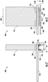
FIG. 2 illustrates a side view of implements of an elevator system that may employ various embodiments of the present disclosure; and -
FIG. 3 illustrates a front view of implements of an elevator system that may employ various embodiments of the present disclosure. -
FIG. 1 is a perspective view of anelevator system 101 including anelevator car 103, acounterweight 105, atension member 107, aguide rail 109, amachine 111, aposition reference system 113, and acontroller 115. Theelevator car 103 andcounterweight 105 are connected to each other by thetension member 107. Thetension member 107 may include or be configured as, for example, ropes, steel cables, and/or coated-steel belts. Thecounterweight 105 is configured to balance a load of theelevator car 103 and is configured to facilitate movement of theelevator car 103 concurrently and in an opposite direction with respect to thecounterweight 105 within anelevator shaft 117 and along theguide rail 109. - The
tension member 107 engages themachine 111, which is part of an overhead structure of theelevator system 101. Themachine 111 is configured to control movement between theelevator car 103 and thecounterweight 105. Theposition reference system 113 may be mounted on a fixed part at the top of theelevator shaft 117, such as on a support or guide rail, and may be configured to provide position signals related to a position of theelevator car 103 within theelevator shaft 117. In other embodiments, theposition reference system 113 may be directly mounted to a moving component of themachine 111, or may be located in other positions and/or configurations as known in the art. Theposition reference system 113 can be any device or mechanism for monitoring a position of an elevator car and/or counter weight, as known in the art. For example, without limitation, theposition reference system 113 can be an encoder, sensor, or other system and can include velocity sensing, absolute position sensing, etc., as will be appreciated by those of skill in the art. - The
controller 115 is located, as shown, in acontroller room 121 of theelevator shaft 117 and is configured to control the operation of theelevator system 101, and particularly theelevator car 103. For example, thecontroller 115 may provide drive signals to themachine 111 to control the acceleration, deceleration, leveling, stopping, etc. of theelevator car 103. Thecontroller 115 may also be configured to receive position signals from theposition reference system 113 or any other desired position reference device. When moving up or down within theelevator shaft 117 alongguide rail 109, theelevator car 103 may stop at one ormore landings 125 as controlled by thecontroller 115. Although shown in acontroller room 121, those of skill in the art will appreciate that thecontroller 115 can be located and/or configured in other locations or positions within theelevator system 101. In one embodiment, the controller may be located remotely or in the cloud. - The
machine 111 may include a motor or similar driving mechanism. In accordance with embodiments of the disclosure, themachine 111 is configured to include an electrically driven motor. The power supply for the motor may be any power source, including a power grid, which, in combination with other components, is supplied to the motor. Themachine 111 may include a traction sheave that imparts force totension member 107 to move theelevator car 103 withinelevator shaft 117. - Although shown and described with a roping system including
tension member 107, elevator systems that employ other methods and mechanisms of moving an elevator car within an elevator shaft may employ embodiments of the present disclosure. For example, embodiments may be employed in ropeless elevator systems using a linear motor to impart motion to an elevator car. Embodiments may also be employed in ropeless elevator systems using a hydraulic lift to impart motion to an elevator car.FIG. 1 is merely a non-limiting example presented for illustrative and explanatory purposes. - The following figures illustrate additional technical features associated with one or more disclosed embodiments. Features disclosed in the following figures having nomenclature similar to features disclosed in
FIG. 1 may be similarly construed though being positively reintroduced with numerical identifiers that may differ from those inFIG. 1 . - Turning to
FIGS. 2 and 3 , disclosed is anelevator system 200. Thesystem 200 includes adoor panel 210 configured for moving along afirst axis 220 for opening and closing of thedoor panel 210 at anentryway 230. Thedoor panel 210 includes adoor magnet 240. Thedoor panel 210 as identified herein may be a bottom half of an elevator door, where a top half (not illustrated) is guided by typical means such as rollers/rails. - The
entryway 230 including asill 250. Thesill 250 has asill magnet 260. Thedoor magnet 240 and thesill magnet 260 may be configured for forming a first magnetic pairing. According to an embodiment the first magnetic pairing guides thedoor panel 210 to move along thefirst axis 220 and prevents thedoor panel 210 from moving in a lateral direction with respect to thefirst axis 220. For example, the first magnetic pairing prevents the door from swinging inwardly and outwardly with respect to theentryway 230, laterally with respect to thefirst axis 220, to thereby avoid interaction with passengers. Sizing and configuring of the magnets may provide for such restrictive motion. - With the use of magnets for guiding the door panel, a top surface of the sill that faces a bottom of the door panel may without guide-tracks. For example, the surface may without inset guide grooves so that it be a flat-planar surface or may contain surface indicia to enable walking traction. That is, the surface may exclude grooves associated with other door panel guide configurations.
- According to an embodiment, the first magnetic pairing may be passive. This prevents providing an additional electrical burden on the elevator system. In one embodiment,
platform structures 235 of theentryway 230 are non-ferrous metals to avoid biasing the magnets. - In one embodiment the
door panel 210 may include abase 270. The base 270 may be defined by a bottom portion of thedoor panel 210. Thedoor magnet 240 may be disposed at or proximate thebase 270. - In one embodiment the
sill 250 may include asill enclosure 290 that is sealed. Thesill magnet 260 may be disposed within thesill enclosure 290. Thesill enclosure 290 may include atrack 300 that extends along thefirst axis 220. Thesill magnet 260 may be movable along thetrack 300 for traveling along thefirst axis 220 with thefirst magnet 240. Thesill magnet 260 may be movably supported on thetrack 300 by at least oneroller 310. - The
door magnet 240 may be a first set of magnets that comprises afirst magnet 320 and asecond magnet 330 spaced along thefirst axis 220 by a first distance. Thesill magnet 260 may be a second set of magnets that comprises athird magnet 340 and afourth magnet 350 that are spaced along thefirst axis 220 by the first distance. From this configuration, as thedoor panel 210 moves along thefirst axis 220, thefirst magnet 320 may be aligned with thethird magnet 340 and thesecond magnet 330 may be aligned with thefourth magnet 350. - The
third magnet 340 and thefourth magnet 350 may be spaced by amechanical spacer 360. Themechanical spacer 360 may extend along thefirst axis 220. Themechanical spacer 360 may be a frame structure such as a bar, a cylinder or other formed or machined member. - The
track 300 may include a pair of track rails, including afirst track rail 370 and asecond track rail 380. The pair of track rails 370, 380 may extend along the first axis and may be spaced from each other in the lateral direction. In one embodiment thethird magnet 340 and thefourth magnet 350 each comprise afirst roller 390 of the at least oneroller 310 that that travels on thefirst track rail 370 and asecond roller 400 of the at least oneroller 310 that travels on thesecond track rail 380. As illustrated thefirst roller 390 and thesecond roller 400 are each a pair of rollers. - In order to optimize a utilization of the available magnetic strength, a spacing D1 between a bottom of the
panel 210 and thesill 250 may be a few millimeters, such as three millimeters. For the same reason, a thickness of thesill 250 may be the same as D1. Thesill 250 may be designed to accommodate such thickness without buckling under the weight of normal use. For example, thesill 250 may be a reinforced and/or composite material. In addition, the thickness of thesill 250 may change between areas A1 where the magnets are directly below thesill 250 and, for example, areas A2 where the rollers are directly below thesill 250. That is, areas where the rollers are directly below thesill 250 may be thicker than areas magnets are directly below thesill 250. - The above disclosed embodiments provide a plurality of sets of paired magnets including a first set of magnets within a door panel and a second set of magnets underneath the sill. The door may be guided along a travel path without the need of a groove. Such configuration may eliminating a formation of debris that may otherwise impeding door movement. Magnet sets may be configured, for example, with magnetic strength characteristics that may prevent door movement out of a door sliding axis. In one embodiment the magnets are rare earth magnets such as neodymium. Magnetic attraction may be passive rather than requiring power to avoid affecting power requirements for the elevator system.
- Alternatively electromagnets may be utilized. If electromagnets are used, such magnets may be used in either the door or sill of the assembly. Placing electromagnets in the sill may avoid providing power to the door panels. In addition, electrical cables for a sill electromagnet may be hidden behind a toe guard positioned behind the sill.
- Within the sill, magnets may be placed on rollers to enable traveling of the magnets in the door sliding axis. The rollers may be placed in enclosed track, thereby being insulated from debris. The sill magnets may be provided as a plurality of sets spaced along the door sliding axis and the door magnet may be provided as a plurality of sets spaced along the door sliding axis. Spacing between the plurality of sets of sill magnets may obtained, for example, by a mechanical connection between the plurality of sets of sill magnets. Such spacing between the sets of sill magnets and sets of door magnets may the same to provide for control of the door panel.
- Various benefits of the disclosed embodiments include reduced of unscheduled elevator maintenance due to removal of a groove based opportunity to collect debris. In addition, noise associated with mechanical interaction between protrusions and grooves and groove guides.
- The terminology used herein is for the purpose of describing particular embodiments only and is not intended to be limiting of the present disclosure. As used herein, the singular forms "a", "an" and "the" are intended to include the plural forms as well, unless the context clearly indicates otherwise. It will be further understood that the terms "comprises" and/or "comprising," when used in this specification, specify the presence of stated features, integers, steps, operations, elements, and/or components, but do not preclude the presence or addition of one or more other features, integers, steps, operations, element components, and/or groups thereof.
- Those of skill in the art will appreciate that various example embodiments are shown and described herein, each having certain features in the particular embodiments, but the present disclosure is not thus limited. Rather, the present disclosure can be modified to incorporate any number of variations, alterations, substitutions, combinations, sub-combinations, or equivalent arrangements not heretofore described, but which are commensurate with the scope of the present disclosure. Additionally, while various embodiments of the present disclosure have been described, it is to be understood that aspects of the present disclosure may include only some of the described embodiments. Accordingly, the present disclosure is not to be seen as limited by the foregoing description, but is only limited by the scope of the appended claims.
Claims (15)
- An elevator system comprising:a door panel configured for moving along a first axis for opening and closing of the door panel at an entryway, the door panel comprising a door magnet,the entryway including a sill, the sill having a sill magnet, wherein the door magnet and the sill magnet are configured for forming a first magnetic pairing, andwherein the first magnetic pairing guides the door panel to move along the first axis and prevents the door panel from moving in a lateral direction with respect to the first axis.
- The system of claim 1, wherein a top surface of the sill is without inset guide grooves.
- The system of claim 1 or2, wherein the door panel comprises a base and the door magnet is at or proximate the base.
- The system of any preceding claim, wherein the sill includes a sill enclosure that is sealed, and the sill magnet is within the sill enclosure.
- The system of claim 4, wherein the sill enclosure includes a track that extends along the first axis and the sill magnet is movable along the track for traveling in the first axis with the door magnet when the door is opening and closing.
- The system of claim 5, wherein the sill magnet is movably supported on the track by at least one roller.
- The system of claim 6, wherein:the door magnet is a first set of magnets that comprises a first magnet and a second magnet spaced along the first axis by a first distance,the sill magnet is a second set of magnets that comprises a third magnet and a fourth magnet that are spaced along the first axis by the first distance,whereby as the door panel moves along the first axis, the first magnet is aligned with the third magnet and the second magnet is aligned with the fourth magnet.
- The system of claim 7, wherein the third magnet and the fourth magnet are spaced by a mechanical spacer that extend along the first axis.
- The system of claim 8, wherein:the track includes a pair of track rails, including a first track rail and a second track rail, the pair of track rails extending along the first axis and being spaced from each other in the lateral direction; andthe third magnet and the fourth magnet each comprise:a first roller of the at least one roller, the first roller traveling on the first track rail; anda second roller of the at least one roller, the second roller traveling on the second track rail.
- The system of claim 9, wherein the first roller and the second roller are each a pair of rollers.
- A method of configuring an elevator system comprising:configuring a door panel for moving along a first axis for opening and closing of the door panel at an entryway, the door panel comprising a door magnet, wherein the entryway includes a sill, the sill includes a sill magnet, andconfiguring the door magnet and the sill magnet for forming a first magnetic pairing, wherein the first magnetic pairing guides the door panel to move along the first axis and prevents the door panel from moving in a lateral direction with respect to the first axis.
- The method of claim 11, wherein a top surface of the sill is without inset guide grooves, and/or
wherein the door panel comprises a base and the door magnet is at or proximate the base, and/or
wherein the sill includes a sill enclosure that is sealed, and the sill magnet is within the sill enclosure. - The method of claim 11 or 12, wherein the sill enclosure includes a track that extends along the first axis and the sill magnet is movable along the track for traveling in the first axis with the door magnet when the door is opening and closing,
wherein preferably the sill magnet is movably supported on the track by at least one roller. - The method of any of claims 11 to 13, wherein:the door magnet is a first set of magnets that comprises a first magnet and a second magnet spaced along the first axis by a first distance,the sill magnet is a second set of magnets that comprises a third magnet and a fourth magnet that are spaced along the first axis by the first distance, andwhereby as the door panel moves along the first axis, the first magnet is aligned with the third magnet and the second magnet is aligned with the fourth magnet;wherein preferably the third magnet and the fourth magnet are spaced by a mechanical spacer that extend along the first axis.
- The method of claim 14, wherein:the track includes a pair of track rails, including a first track rail and a second track rail, the pair of track rails extending along the first axis and being spaced from each other in the lateral direction; andthe third magnet and the fourth magnet each comprise:a first roller of the at least one roller, the first roller traveling on the first track rail; anda second roller of the at least one roller, the second roller traveling on the second track rail;wherein preferably the first roller and the second roller are each a pair of rollers.
Applications Claiming Priority (1)
| Application Number | Priority Date | Filing Date | Title |
|---|---|---|---|
| US16/275,837 US11148907B2 (en) | 2019-02-14 | 2019-02-14 | Elevator entryway with magnetic guidance for controlling door panel motion |
Publications (2)
| Publication Number | Publication Date |
|---|---|
| EP3696130A1 true EP3696130A1 (en) | 2020-08-19 |
| EP3696130B1 EP3696130B1 (en) | 2024-11-13 |
Family
ID=69147404
Family Applications (1)
| Application Number | Title | Priority Date | Filing Date |
|---|---|---|---|
| EP19217480.3A Active EP3696130B1 (en) | 2019-02-14 | 2019-12-18 | Elevator entryway with magnetic guidance for controlling door panel motion |
Country Status (3)
| Country | Link |
|---|---|
| US (1) | US11148907B2 (en) |
| EP (1) | EP3696130B1 (en) |
| CN (1) | CN111559689B (en) |
Citations (4)
| Publication number | Priority date | Publication date | Assignee | Title |
|---|---|---|---|---|
| JPH09272680A (en) * | 1996-04-03 | 1997-10-21 | Mitsubishi Denki Bill Techno Service Kk | Elevator cage |
| WO2011090369A1 (en) * | 2010-01-22 | 2011-07-28 | Rob Jansen | Sliding door assembly for a shower cabin |
| JP2012076863A (en) * | 2010-09-30 | 2012-04-19 | Toshiba Elevator Co Ltd | Elevator door device |
| CN107265270A (en) * | 2017-07-07 | 2017-10-20 | 苏州易升电梯部件有限公司 | A kind of elevator door lower guide of maglev type |
Family Cites Families (26)
| Publication number | Priority date | Publication date | Assignee | Title |
|---|---|---|---|---|
| EP0668235B1 (en) * | 1994-02-21 | 1999-05-26 | Inventio Ag | Feeding and unlocking system for lift doors |
| EP0741224B1 (en) | 1995-05-05 | 2002-02-20 | Inventio Ag | Sliding door with low friction guide |
| JP2000087636A (en) | 1998-09-09 | 2000-03-28 | Kazumoto Hashizume | Fittings making use of magnet |
| JP2000248820A (en) | 1999-03-04 | 2000-09-12 | Daiichi Kogyo:Kk | Sill for sliding door with sash sheave and door stop member |
| JP2001027069A (en) | 1999-07-13 | 2001-01-30 | Daiichi Kogyo:Kk | Sliding door threshold having sash sheave |
| JP2002167148A (en) * | 2000-12-01 | 2002-06-11 | Mitsubishi Electric Building Techno Service Co Ltd | Cleaning method for window of sliding door and device for the same |
| JP4107879B2 (en) * | 2002-05-17 | 2008-06-25 | 三菱電機株式会社 | Elevator landing door |
| DE20310810U1 (en) * | 2003-07-15 | 2003-09-25 | Laufer, Bernd, 96163 Gundelsheim | Lift has a closed door and a shaft door and a rear wall and two side walls with door sections, tracks have a magnetic moving guide which moves the doors |
| ES2350312T3 (en) * | 2003-09-18 | 2011-01-21 | Otis Elevator Company | ELEVATOR ASSEMBLY WITH EXTENSIBLE THRESHOLD. |
| WO2007018488A1 (en) * | 2005-07-21 | 2007-02-15 | Otis Elevator Company | Controlling elevator door orientation during door movement |
| WO2007073376A1 (en) | 2005-12-21 | 2007-06-28 | Otis Elevator Company | Elevator door guidance assembly |
| KR20080077871A (en) | 2007-02-21 | 2008-08-26 | 정근영 | Door opening and closing device using magnetic force |
| US8020346B2 (en) | 2007-08-16 | 2011-09-20 | Joseph Singiser | Magnetically supported sliding track system |
| JP2011006209A (en) * | 2009-06-26 | 2011-01-13 | Mitsubishi Electric Corp | Door device for elevator |
| WO2011075142A1 (en) * | 2009-12-18 | 2011-06-23 | Otis Elevator Company | Magnetic device for controlling door movement and method thereof |
| CN201619930U (en) * | 2010-01-07 | 2010-11-03 | 曹恒 | Elevator door guide shoe and guide rail device |
| EP2594521A1 (en) | 2010-07-16 | 2013-05-22 | Mitsubishi Electric Corporation | Elevator door assembly |
| ITMO20130050A1 (en) | 2013-02-25 | 2014-08-26 | Rota Infissi S R L | GUIDE SYSTEM FOR SLIDING DOOR. |
| PT106928B (en) * | 2013-05-06 | 2019-05-06 | Hiperjanelas Lda | MAGNETIC LEVERING SYSTEM FOR DOORS AND WINDOWS |
| CN203486718U (en) * | 2013-09-09 | 2014-03-19 | 苏州歌拉瑞电梯有限公司 | Elevator door sliding device |
| CN103485673B (en) * | 2013-09-23 | 2016-02-10 | 深圳市华力特电气股份有限公司 | A kind of metro non-contact type shield door unit and system |
| CN204492514U (en) | 2014-09-16 | 2015-07-22 | 宋伟星 | A kind of shower room sliding door |
| CN104724576B (en) * | 2015-03-30 | 2019-01-18 | 永大电梯设备(中国)有限公司 | Magnet unit and magnetic boot guiding device |
| US20180229973A1 (en) * | 2015-08-31 | 2018-08-16 | Frédéric Beauchaud | Elevator recuperator |
| US10113348B2 (en) | 2016-11-28 | 2018-10-30 | Tony Lam | Magnetic levitating door |
| CN207647339U (en) * | 2017-12-21 | 2018-07-24 | 广州优阳安防建材科技有限公司 | A kind of adaptable electromagnetic levitation type automatically-controlled door |
-
2019
- 2019-02-14 US US16/275,837 patent/US11148907B2/en active Active
- 2019-12-18 EP EP19217480.3A patent/EP3696130B1/en active Active
- 2019-12-31 CN CN201911418945.4A patent/CN111559689B/en active Active
Patent Citations (4)
| Publication number | Priority date | Publication date | Assignee | Title |
|---|---|---|---|---|
| JPH09272680A (en) * | 1996-04-03 | 1997-10-21 | Mitsubishi Denki Bill Techno Service Kk | Elevator cage |
| WO2011090369A1 (en) * | 2010-01-22 | 2011-07-28 | Rob Jansen | Sliding door assembly for a shower cabin |
| JP2012076863A (en) * | 2010-09-30 | 2012-04-19 | Toshiba Elevator Co Ltd | Elevator door device |
| CN107265270A (en) * | 2017-07-07 | 2017-10-20 | 苏州易升电梯部件有限公司 | A kind of elevator door lower guide of maglev type |
Also Published As
| Publication number | Publication date |
|---|---|
| CN111559689A (en) | 2020-08-21 |
| US20200262682A1 (en) | 2020-08-20 |
| EP3696130B1 (en) | 2024-11-13 |
| CN111559689B (en) | 2023-04-18 |
| US11148907B2 (en) | 2021-10-19 |
Similar Documents
| Publication | Publication Date | Title |
|---|---|---|
| US20200055701A1 (en) | Self-propelled elevators and elevator brake systems | |
| KR20170063548A (en) | Elevator system | |
| CN111170101B (en) | Monitoring system | |
| CN1075465A (en) | The personnel transportation system | |
| US10889467B2 (en) | Synchronization based on distance of magnet assembly to rail | |
| JP4531067B2 (en) | Magnetic levitation device | |
| KR20190125952A (en) | Elevator safety gear actuation device | |
| EP3564171A1 (en) | Elevator safety gear actuation device | |
| EP3696130B1 (en) | Elevator entryway with magnetic guidance for controlling door panel motion | |
| US11345570B2 (en) | Electronic safety actuator electromagnetic guidance | |
| JP5343349B2 (en) | Elevator device and vibration suppression device | |
| EP3274285B1 (en) | Elevator system suspension member termination | |
| KR102330510B1 (en) | Ropeless elevator system | |
| JP5031241B2 (en) | Elevator damping device | |
| US12384655B2 (en) | Electrical power transmission to elevator system cars | |
| US20220033214A1 (en) | Solution for overspeed monitoring of an elevator car | |
| WO2022262982A1 (en) | A guide shoe arrangement and an elevator utilizing the guide shoe arrangement | |
| JP2015182870A (en) | Elevator door opening/closing device | |
| JP2014037282A (en) | Elevator car guide mechanism | |
| CN111960230A (en) | Door device and elevator device | |
| TH51017A (en) | Elevator system | |
| HK1251214A1 (en) | Electric linear motor | |
| HK1251214B (en) | Electric linear motor |
Legal Events
| Date | Code | Title | Description |
|---|---|---|---|
| PUAI | Public reference made under article 153(3) epc to a published international application that has entered the european phase |
Free format text: ORIGINAL CODE: 0009012 |
|
| STAA | Information on the status of an ep patent application or granted ep patent |
Free format text: STATUS: THE APPLICATION HAS BEEN PUBLISHED |
|
| AK | Designated contracting states |
Kind code of ref document: A1 Designated state(s): AL AT BE BG CH CY CZ DE DK EE ES FI FR GB GR HR HU IE IS IT LI LT LU LV MC MK MT NL NO PL PT RO RS SE SI SK SM TR |
|
| STAA | Information on the status of an ep patent application or granted ep patent |
Free format text: STATUS: REQUEST FOR EXAMINATION WAS MADE |
|
| 17P | Request for examination filed |
Effective date: 20210216 |
|
| RBV | Designated contracting states (corrected) |
Designated state(s): AL AT BE BG CH CY CZ DE DK EE ES FI FR GB GR HR HU IE IS IT LI LT LU LV MC MK MT NL NO PL PT RO RS SE SI SK SM TR |
|
| STAA | Information on the status of an ep patent application or granted ep patent |
Free format text: STATUS: EXAMINATION IS IN PROGRESS |
|
| 17Q | First examination report despatched |
Effective date: 20221212 |
|
| GRAP | Despatch of communication of intention to grant a patent |
Free format text: ORIGINAL CODE: EPIDOSNIGR1 |
|
| STAA | Information on the status of an ep patent application or granted ep patent |
Free format text: STATUS: GRANT OF PATENT IS INTENDED |
|
| INTG | Intention to grant announced |
Effective date: 20240613 |
|
| GRAS | Grant fee paid |
Free format text: ORIGINAL CODE: EPIDOSNIGR3 |
|
| GRAA | (expected) grant |
Free format text: ORIGINAL CODE: 0009210 |
|
| STAA | Information on the status of an ep patent application or granted ep patent |
Free format text: STATUS: THE PATENT HAS BEEN GRANTED |
|
| AK | Designated contracting states |
Kind code of ref document: B1 Designated state(s): AL AT BE BG CH CY CZ DE DK EE ES FI FR GB GR HR HU IE IS IT LI LT LU LV MC MK MT NL NO PL PT RO RS SE SI SK SM TR |
|
| REG | Reference to a national code |
Ref country code: GB Ref legal event code: FG4D |
|
| REG | Reference to a national code |
Ref country code: CH Ref legal event code: EP |
|
| REG | Reference to a national code |
Ref country code: IE Ref legal event code: FG4D |
|
| REG | Reference to a national code |
Ref country code: DE Ref legal event code: R096 Ref document number: 602019061851 Country of ref document: DE |
|
| REG | Reference to a national code |
Ref country code: LT Ref legal event code: MG9D |
|
| REG | Reference to a national code |
Ref country code: NL Ref legal event code: MP Effective date: 20241113 |
|
| PG25 | Lapsed in a contracting state [announced via postgrant information from national office to epo] |
Ref country code: PT Free format text: LAPSE BECAUSE OF FAILURE TO SUBMIT A TRANSLATION OF THE DESCRIPTION OR TO PAY THE FEE WITHIN THE PRESCRIBED TIME-LIMIT Effective date: 20250313 Ref country code: HR Free format text: LAPSE BECAUSE OF FAILURE TO SUBMIT A TRANSLATION OF THE DESCRIPTION OR TO PAY THE FEE WITHIN THE PRESCRIBED TIME-LIMIT Effective date: 20241113 Ref country code: IS Free format text: LAPSE BECAUSE OF FAILURE TO SUBMIT A TRANSLATION OF THE DESCRIPTION OR TO PAY THE FEE WITHIN THE PRESCRIBED TIME-LIMIT Effective date: 20250313 |
|
| PG25 | Lapsed in a contracting state [announced via postgrant information from national office to epo] |
Ref country code: FI Free format text: LAPSE BECAUSE OF FAILURE TO SUBMIT A TRANSLATION OF THE DESCRIPTION OR TO PAY THE FEE WITHIN THE PRESCRIBED TIME-LIMIT Effective date: 20241113 Ref country code: NL Free format text: LAPSE BECAUSE OF FAILURE TO SUBMIT A TRANSLATION OF THE DESCRIPTION OR TO PAY THE FEE WITHIN THE PRESCRIBED TIME-LIMIT Effective date: 20241113 |
|
| REG | Reference to a national code |
Ref country code: AT Ref legal event code: MK05 Ref document number: 1741573 Country of ref document: AT Kind code of ref document: T Effective date: 20241113 |
|
| PG25 | Lapsed in a contracting state [announced via postgrant information from national office to epo] |
Ref country code: BG Free format text: LAPSE BECAUSE OF FAILURE TO SUBMIT A TRANSLATION OF THE DESCRIPTION OR TO PAY THE FEE WITHIN THE PRESCRIBED TIME-LIMIT Effective date: 20241113 |
|
| PG25 | Lapsed in a contracting state [announced via postgrant information from national office to epo] |
Ref country code: ES Free format text: LAPSE BECAUSE OF FAILURE TO SUBMIT A TRANSLATION OF THE DESCRIPTION OR TO PAY THE FEE WITHIN THE PRESCRIBED TIME-LIMIT Effective date: 20241113 |
|
| PG25 | Lapsed in a contracting state [announced via postgrant information from national office to epo] |
Ref country code: NO Free format text: LAPSE BECAUSE OF FAILURE TO SUBMIT A TRANSLATION OF THE DESCRIPTION OR TO PAY THE FEE WITHIN THE PRESCRIBED TIME-LIMIT Effective date: 20250213 |
|
| PG25 | Lapsed in a contracting state [announced via postgrant information from national office to epo] |
Ref country code: LV Free format text: LAPSE BECAUSE OF FAILURE TO SUBMIT A TRANSLATION OF THE DESCRIPTION OR TO PAY THE FEE WITHIN THE PRESCRIBED TIME-LIMIT Effective date: 20241113 Ref country code: GR Free format text: LAPSE BECAUSE OF FAILURE TO SUBMIT A TRANSLATION OF THE DESCRIPTION OR TO PAY THE FEE WITHIN THE PRESCRIBED TIME-LIMIT Effective date: 20250214 Ref country code: AT Free format text: LAPSE BECAUSE OF FAILURE TO SUBMIT A TRANSLATION OF THE DESCRIPTION OR TO PAY THE FEE WITHIN THE PRESCRIBED TIME-LIMIT Effective date: 20241113 |
|
| PG25 | Lapsed in a contracting state [announced via postgrant information from national office to epo] |
Ref country code: PL Free format text: LAPSE BECAUSE OF FAILURE TO SUBMIT A TRANSLATION OF THE DESCRIPTION OR TO PAY THE FEE WITHIN THE PRESCRIBED TIME-LIMIT Effective date: 20241113 |
|
| PG25 | Lapsed in a contracting state [announced via postgrant information from national office to epo] |
Ref country code: RS Free format text: LAPSE BECAUSE OF FAILURE TO SUBMIT A TRANSLATION OF THE DESCRIPTION OR TO PAY THE FEE WITHIN THE PRESCRIBED TIME-LIMIT Effective date: 20250213 |
|
| PG25 | Lapsed in a contracting state [announced via postgrant information from national office to epo] |
Ref country code: SM Free format text: LAPSE BECAUSE OF FAILURE TO SUBMIT A TRANSLATION OF THE DESCRIPTION OR TO PAY THE FEE WITHIN THE PRESCRIBED TIME-LIMIT Effective date: 20241113 |
|
| PG25 | Lapsed in a contracting state [announced via postgrant information from national office to epo] |
Ref country code: DK Free format text: LAPSE BECAUSE OF FAILURE TO SUBMIT A TRANSLATION OF THE DESCRIPTION OR TO PAY THE FEE WITHIN THE PRESCRIBED TIME-LIMIT Effective date: 20241113 |
|
| PG25 | Lapsed in a contracting state [announced via postgrant information from national office to epo] |
Ref country code: EE Free format text: LAPSE BECAUSE OF FAILURE TO SUBMIT A TRANSLATION OF THE DESCRIPTION OR TO PAY THE FEE WITHIN THE PRESCRIBED TIME-LIMIT Effective date: 20241113 |
|
| PG25 | Lapsed in a contracting state [announced via postgrant information from national office to epo] |
Ref country code: RO Free format text: LAPSE BECAUSE OF FAILURE TO SUBMIT A TRANSLATION OF THE DESCRIPTION OR TO PAY THE FEE WITHIN THE PRESCRIBED TIME-LIMIT Effective date: 20241113 |
|
| PG25 | Lapsed in a contracting state [announced via postgrant information from national office to epo] |
Ref country code: SK Free format text: LAPSE BECAUSE OF FAILURE TO SUBMIT A TRANSLATION OF THE DESCRIPTION OR TO PAY THE FEE WITHIN THE PRESCRIBED TIME-LIMIT Effective date: 20241113 |
|
| PG25 | Lapsed in a contracting state [announced via postgrant information from national office to epo] |
Ref country code: CZ Free format text: LAPSE BECAUSE OF FAILURE TO SUBMIT A TRANSLATION OF THE DESCRIPTION OR TO PAY THE FEE WITHIN THE PRESCRIBED TIME-LIMIT Effective date: 20241113 |
|
| PG25 | Lapsed in a contracting state [announced via postgrant information from national office to epo] |
Ref country code: IT Free format text: LAPSE BECAUSE OF FAILURE TO SUBMIT A TRANSLATION OF THE DESCRIPTION OR TO PAY THE FEE WITHIN THE PRESCRIBED TIME-LIMIT Effective date: 20241113 |
|
| REG | Reference to a national code |
Ref country code: CH Ref legal event code: PL |
|
| REG | Reference to a national code |
Ref country code: DE Ref legal event code: R097 Ref document number: 602019061851 Country of ref document: DE |
|
| PG25 | Lapsed in a contracting state [announced via postgrant information from national office to epo] |
Ref country code: LU Free format text: LAPSE BECAUSE OF NON-PAYMENT OF DUE FEES Effective date: 20241218 |
|
| PG25 | Lapsed in a contracting state [announced via postgrant information from national office to epo] |
Ref country code: SE Free format text: LAPSE BECAUSE OF FAILURE TO SUBMIT A TRANSLATION OF THE DESCRIPTION OR TO PAY THE FEE WITHIN THE PRESCRIBED TIME-LIMIT Effective date: 20241113 |
|
| PG25 | Lapsed in a contracting state [announced via postgrant information from national office to epo] |
Ref country code: MC Free format text: LAPSE BECAUSE OF FAILURE TO SUBMIT A TRANSLATION OF THE DESCRIPTION OR TO PAY THE FEE WITHIN THE PRESCRIBED TIME-LIMIT Effective date: 20241113 |
|
| PLBE | No opposition filed within time limit |
Free format text: ORIGINAL CODE: 0009261 |
|
| STAA | Information on the status of an ep patent application or granted ep patent |
Free format text: STATUS: NO OPPOSITION FILED WITHIN TIME LIMIT |
|
| REG | Reference to a national code |
Ref country code: BE Ref legal event code: MM Effective date: 20241231 |
|
| PG25 | Lapsed in a contracting state [announced via postgrant information from national office to epo] |
Ref country code: BE Free format text: LAPSE BECAUSE OF NON-PAYMENT OF DUE FEES Effective date: 20241231 |
|
| PG25 | Lapsed in a contracting state [announced via postgrant information from national office to epo] |
Ref country code: CH Free format text: LAPSE BECAUSE OF NON-PAYMENT OF DUE FEES Effective date: 20241231 |
|
| 26N | No opposition filed |
Effective date: 20250814 |
|
| PG25 | Lapsed in a contracting state [announced via postgrant information from national office to epo] |
Ref country code: IE Free format text: LAPSE BECAUSE OF NON-PAYMENT OF DUE FEES Effective date: 20241218 |
|
| GBPC | Gb: european patent ceased through non-payment of renewal fee |
Effective date: 20250213 |
|
| PGFP | Annual fee paid to national office [announced via postgrant information from national office to epo] |
Ref country code: DE Payment date: 20251126 Year of fee payment: 7 |
|
| PG25 | Lapsed in a contracting state [announced via postgrant information from national office to epo] |
Ref country code: GB Free format text: LAPSE BECAUSE OF NON-PAYMENT OF DUE FEES Effective date: 20250213 |
|
| PGFP | Annual fee paid to national office [announced via postgrant information from national office to epo] |
Ref country code: FR Payment date: 20251120 Year of fee payment: 7 |
|
| PG25 | Lapsed in a contracting state [announced via postgrant information from national office to epo] |
Ref country code: CY Free format text: LAPSE BECAUSE OF FAILURE TO SUBMIT A TRANSLATION OF THE DESCRIPTION OR TO PAY THE FEE WITHIN THE PRESCRIBED TIME-LIMIT Effective date: 20241113 |