EP3695992A1 - Control arm clamping process consisting of two shaped and welded laser parts - Google Patents
Control arm clamping process consisting of two shaped and welded laser parts Download PDFInfo
- Publication number
- EP3695992A1 EP3695992A1 EP20152082.2A EP20152082A EP3695992A1 EP 3695992 A1 EP3695992 A1 EP 3695992A1 EP 20152082 A EP20152082 A EP 20152082A EP 3695992 A1 EP3695992 A1 EP 3695992A1
- Authority
- EP
- European Patent Office
- Prior art keywords
- fixed
- tube
- laser welding
- section
- laser
- Prior art date
- Legal status (The legal status is an assumption and is not a legal conclusion. Google has not performed a legal analysis and makes no representation as to the accuracy of the status listed.)
- Withdrawn
Links
- 238000000034 method Methods 0.000 title claims abstract description 26
- 230000008569 process Effects 0.000 title claims abstract description 21
- 238000003466 welding Methods 0.000 claims abstract description 29
- 239000000725 suspension Substances 0.000 claims abstract description 10
- 230000008878 coupling Effects 0.000 claims description 5
- 238000010168 coupling process Methods 0.000 claims description 5
- 238000005859 coupling reaction Methods 0.000 claims description 5
- 238000005304 joining Methods 0.000 abstract description 4
- 238000004519 manufacturing process Methods 0.000 abstract description 4
- 238000002513 implantation Methods 0.000 abstract 1
- 238000006467 substitution reaction Methods 0.000 abstract 1
- 238000010891 electric arc Methods 0.000 description 4
- 230000008859 change Effects 0.000 description 2
- 239000012467 final product Substances 0.000 description 2
- 230000006872 improvement Effects 0.000 description 2
- 239000000463 material Substances 0.000 description 2
- 239000000047 product Substances 0.000 description 2
- 241001247986 Calotropis procera Species 0.000 description 1
- 239000007795 chemical reaction product Substances 0.000 description 1
- 230000003534 oscillatory effect Effects 0.000 description 1
- 230000009467 reduction Effects 0.000 description 1
- 238000011076 safety test Methods 0.000 description 1
- 238000010200 validation analysis Methods 0.000 description 1
Images



Classifications
-
- B—PERFORMING OPERATIONS; TRANSPORTING
- B23—MACHINE TOOLS; METAL-WORKING NOT OTHERWISE PROVIDED FOR
- B23K—SOLDERING OR UNSOLDERING; WELDING; CLADDING OR PLATING BY SOLDERING OR WELDING; CUTTING BY APPLYING HEAT LOCALLY, e.g. FLAME CUTTING; WORKING BY LASER BEAM
- B23K26/00—Working by laser beam, e.g. welding, cutting or boring
- B23K26/20—Bonding
- B23K26/21—Bonding by welding
-
- B—PERFORMING OPERATIONS; TRANSPORTING
- B60—VEHICLES IN GENERAL
- B60G—VEHICLE SUSPENSION ARRANGEMENTS
- B60G7/00—Pivoted suspension arms; Accessories thereof
- B60G7/001—Suspension arms, e.g. constructional features
-
- B—PERFORMING OPERATIONS; TRANSPORTING
- B23—MACHINE TOOLS; METAL-WORKING NOT OTHERWISE PROVIDED FOR
- B23K—SOLDERING OR UNSOLDERING; WELDING; CLADDING OR PLATING BY SOLDERING OR WELDING; CUTTING BY APPLYING HEAT LOCALLY, e.g. FLAME CUTTING; WORKING BY LASER BEAM
- B23K26/00—Working by laser beam, e.g. welding, cutting or boring
- B23K26/20—Bonding
- B23K26/21—Bonding by welding
- B23K26/24—Seam welding
- B23K26/244—Overlap seam welding
-
- B—PERFORMING OPERATIONS; TRANSPORTING
- B23—MACHINE TOOLS; METAL-WORKING NOT OTHERWISE PROVIDED FOR
- B23K—SOLDERING OR UNSOLDERING; WELDING; CLADDING OR PLATING BY SOLDERING OR WELDING; CUTTING BY APPLYING HEAT LOCALLY, e.g. FLAME CUTTING; WORKING BY LASER BEAM
- B23K26/00—Working by laser beam, e.g. welding, cutting or boring
- B23K26/20—Bonding
- B23K26/21—Bonding by welding
- B23K26/24—Seam welding
- B23K26/28—Seam welding of curved planar seams
-
- B—PERFORMING OPERATIONS; TRANSPORTING
- B23—MACHINE TOOLS; METAL-WORKING NOT OTHERWISE PROVIDED FOR
- B23K—SOLDERING OR UNSOLDERING; WELDING; CLADDING OR PLATING BY SOLDERING OR WELDING; CUTTING BY APPLYING HEAT LOCALLY, e.g. FLAME CUTTING; WORKING BY LASER BEAM
- B23K26/00—Working by laser beam, e.g. welding, cutting or boring
- B23K26/20—Bonding
- B23K26/21—Bonding by welding
- B23K26/24—Seam welding
- B23K26/28—Seam welding of curved planar seams
- B23K26/282—Seam welding of curved planar seams of tube sections
-
- B—PERFORMING OPERATIONS; TRANSPORTING
- B23—MACHINE TOOLS; METAL-WORKING NOT OTHERWISE PROVIDED FOR
- B23K—SOLDERING OR UNSOLDERING; WELDING; CLADDING OR PLATING BY SOLDERING OR WELDING; CUTTING BY APPLYING HEAT LOCALLY, e.g. FLAME CUTTING; WORKING BY LASER BEAM
- B23K37/00—Auxiliary devices or processes, not specially adapted for a procedure covered by only one of the other main groups of this subclass
- B23K37/04—Auxiliary devices or processes, not specially adapted for a procedure covered by only one of the other main groups of this subclass for holding or positioning work
- B23K37/0426—Fixtures for other work
- B23K37/0435—Clamps
-
- B—PERFORMING OPERATIONS; TRANSPORTING
- B23—MACHINE TOOLS; METAL-WORKING NOT OTHERWISE PROVIDED FOR
- B23K—SOLDERING OR UNSOLDERING; WELDING; CLADDING OR PLATING BY SOLDERING OR WELDING; CUTTING BY APPLYING HEAT LOCALLY, e.g. FLAME CUTTING; WORKING BY LASER BEAM
- B23K2101/00—Articles made by soldering, welding or cutting
- B23K2101/006—Vehicles
-
- B—PERFORMING OPERATIONS; TRANSPORTING
- B23—MACHINE TOOLS; METAL-WORKING NOT OTHERWISE PROVIDED FOR
- B23K—SOLDERING OR UNSOLDERING; WELDING; CLADDING OR PLATING BY SOLDERING OR WELDING; CUTTING BY APPLYING HEAT LOCALLY, e.g. FLAME CUTTING; WORKING BY LASER BEAM
- B23K2101/00—Articles made by soldering, welding or cutting
- B23K2101/18—Sheet panels
- B23K2101/185—Tailored blanks
-
- B—PERFORMING OPERATIONS; TRANSPORTING
- B23—MACHINE TOOLS; METAL-WORKING NOT OTHERWISE PROVIDED FOR
- B23K—SOLDERING OR UNSOLDERING; WELDING; CLADDING OR PLATING BY SOLDERING OR WELDING; CUTTING BY APPLYING HEAT LOCALLY, e.g. FLAME CUTTING; WORKING BY LASER BEAM
- B23K2103/00—Materials to be soldered, welded or cut
- B23K2103/02—Iron or ferrous alloys
- B23K2103/04—Steel or steel alloys
-
- B—PERFORMING OPERATIONS; TRANSPORTING
- B60—VEHICLES IN GENERAL
- B60G—VEHICLE SUSPENSION ARRANGEMENTS
- B60G2206/00—Indexing codes related to the manufacturing of suspensions: constructional features, the materials used, procedures or tools
- B60G2206/01—Constructional features of suspension elements, e.g. arms, dampers, springs
- B60G2206/017—Constructional features of suspension elements, e.g. arms, dampers, springs forming an eye for the bushing
-
- B—PERFORMING OPERATIONS; TRANSPORTING
- B60—VEHICLES IN GENERAL
- B60G—VEHICLE SUSPENSION ARRANGEMENTS
- B60G2206/00—Indexing codes related to the manufacturing of suspensions: constructional features, the materials used, procedures or tools
- B60G2206/01—Constructional features of suspension elements, e.g. arms, dampers, springs
- B60G2206/10—Constructional features of arms
- B60G2206/122—Constructional features of arms the arm having L-shape
-
- B—PERFORMING OPERATIONS; TRANSPORTING
- B60—VEHICLES IN GENERAL
- B60G—VEHICLE SUSPENSION ARRANGEMENTS
- B60G2206/00—Indexing codes related to the manufacturing of suspensions: constructional features, the materials used, procedures or tools
- B60G2206/01—Constructional features of suspension elements, e.g. arms, dampers, springs
- B60G2206/10—Constructional features of arms
- B60G2206/16—Constructional features of arms the arm having a U profile and/or made of a plate
-
- B—PERFORMING OPERATIONS; TRANSPORTING
- B60—VEHICLES IN GENERAL
- B60G—VEHICLE SUSPENSION ARRANGEMENTS
- B60G2206/00—Indexing codes related to the manufacturing of suspensions: constructional features, the materials used, procedures or tools
- B60G2206/01—Constructional features of suspension elements, e.g. arms, dampers, springs
- B60G2206/70—Materials used in suspensions
- B60G2206/72—Steel
- B60G2206/722—Plates
-
- B—PERFORMING OPERATIONS; TRANSPORTING
- B60—VEHICLES IN GENERAL
- B60G—VEHICLE SUSPENSION ARRANGEMENTS
- B60G2206/00—Indexing codes related to the manufacturing of suspensions: constructional features, the materials used, procedures or tools
- B60G2206/01—Constructional features of suspension elements, e.g. arms, dampers, springs
- B60G2206/80—Manufacturing procedures
- B60G2206/81—Shaping
- B60G2206/8102—Shaping by stamping
-
- B—PERFORMING OPERATIONS; TRANSPORTING
- B60—VEHICLES IN GENERAL
- B60G—VEHICLE SUSPENSION ARRANGEMENTS
- B60G2206/00—Indexing codes related to the manufacturing of suspensions: constructional features, the materials used, procedures or tools
- B60G2206/01—Constructional features of suspension elements, e.g. arms, dampers, springs
- B60G2206/80—Manufacturing procedures
- B60G2206/82—Joining
- B60G2206/8201—Joining by welding
Definitions
- the present invention concerns the method of fixing a lower swing arm for front suspension of a motor vehicle, composed of shaped and machined components, which are fixed to each other by laser welding, becoming a single piece ready for to be used in the assembly of motor vehicles.
- the swing arm part, part of the front suspension assembly of automotive vehicles plays a structural and dynamic role during vehicle operation and is responsible for ensuring safety, efficiency and controllability in various situations during its use.
- the approval of the swing arm for use in motor vehicles depends on virtual and physical tests that assess mechanical stress, distortions and fatigue strength under predefined situations, so as to ensure the quality and safety of the end product.
- the high thermal input applied to the components joined through electric arc welding and spot welding is the main aggravating factor in the failure of the part, which is subjected to rigorous safety tests during its validation and approval phase.
- This thermal input is responsible for severely reducing the strength of the part when under stress, which is the main reason for failure in physical and virtual tests.
- it is also responsible for imposing part deformations that impact the final quality, as well as influencing the dimensional quality tests.
- the present invention offers a change in the union of the swing arm components. Because it is made by means of an autogenous oscillating arm clamping process by laser welding, with significant improvements in efficiency and economy in the production line, since it does not use addition material, presenting a lower thermal input when compared to the clamping by electric arc and spot welding. This low thermal input is considered a solution to the previously mentioned problems, since the reduction in fatigue strength is not so severe and the thermal distortions are smaller.
- the process of attaching a frontal suspension swing arm by laser welding also has secondary benefits to the part quality, including high welding speed, increasing welding cell efficiency, and a wider access to the component attachment points, as the robot does not need to be in direct contact with the region to be welded.
- the laser welding oscillating swing arm clamping process offers an opportunity for improvement and efficiency in relation to the state of the art, thus influencing the quality of the final product.
- the resulting components of the forming process have dimensional and geometric tolerances that do not always match the requirements for the correct application of the laser welding process.
- Laser welding on the other hand, as it is an autogenous joining process, requires a coupling of plates with low permissiveness of empty spaces.
- devices that compensate for the dimensional variations resulting from the forming process so that the joining process is correctly executed. These devices are blocks machined in the nominal form of the part, compressed under the components themselves by high load actuators, forcing them to take the appropriate form for the application of welding, without the presence of voids.
- the suspension arm is composed of two cold formed plates (4, 5), with a flanged region (6) in one of its extremities, a cylindrical pin (8), a tube of smaller circular section (7) wrapped to the aforementioned pin, a tube of larger circular section (9), laser welded (11, 12, 13, 14), used as housing for a rubber bushing (2), a socket joint (3), a cylindrical rubber bushing (2) and a bushing with clamping flanges (1), or optionally in place of the cylindrical pin (8), a smaller circular cross-section tube (7) and a bushing with clamping flanges (1), the vertically clamped rubber bushing (15) can be used in the two already laser-welded shaped plates (4, 5). These components together form the final product, which is connected at two anchor points on the vehicle's crossbar and at one anchor point on the vehicle's baseplate, working in vertical oscillatory movements during its use.
Landscapes
- Engineering & Computer Science (AREA)
- Physics & Mathematics (AREA)
- Optics & Photonics (AREA)
- Mechanical Engineering (AREA)
- Plasma & Fusion (AREA)
- Vehicle Body Suspensions (AREA)
- Laser Beam Processing (AREA)
Abstract
Description
- The present invention concerns the method of fixing a lower swing arm for front suspension of a motor vehicle, composed of shaped and machined components, which are fixed to each other by laser welding, becoming a single piece ready for to be used in the assembly of motor vehicles.
- The swing arm part, part of the front suspension assembly of automotive vehicles, plays a structural and dynamic role during vehicle operation and is responsible for ensuring safety, efficiency and controllability in various situations during its use.
- The approval of the swing arm for use in motor vehicles depends on virtual and physical tests that assess mechanical stress, distortions and fatigue strength under predefined situations, so as to ensure the quality and safety of the end product.
- The current state of this technique has known critical points, mainly due to the fact that the oscillating arm clamping process occurs through electric arc welding and spot welding. This fastening process is traditionally known and mastered by manufacturers and, since it has been around for a long time, has already been added to each one's knowledge. Apart from the above, this process also has limitations regarding the access of the regions to be welded, since there is a need for the welding torch to always be in direct contact with the region to be fixed. In addition, in the case of serial production, the fixing of the swing arm by means of electric arc welding and spot welding is seen as an obstacle in the production line, due to the high time consumed in the process, making it necessary to use of multiple cells in some cases.
- The high thermal input applied to the components joined through electric arc welding and spot welding is the main aggravating factor in the failure of the part, which is subjected to rigorous safety tests during its validation and approval phase. This thermal input is responsible for severely reducing the strength of the part when under stress, which is the main reason for failure in physical and virtual tests. In addition, it is also responsible for imposing part deformations that impact the final quality, as well as influencing the dimensional quality tests.
- Such disadvantages from the state of the art are often offset by the robustness of the product so that it can pass the required tests and by devices that compensate for thermal distortion of the part by applying loads at predetermined points under it.
- The present invention offers a change in the union of the swing arm components. Because it is made by means of an autogenous oscillating arm clamping process by laser welding, with significant improvements in efficiency and economy in the production line, since it does not use addition material, presenting a lower thermal input when compared to the clamping by electric arc and spot welding. This low thermal input is considered a solution to the previously mentioned problems, since the reduction in fatigue strength is not so severe and the thermal distortions are smaller.
- The process of attaching a frontal suspension swing arm by laser welding also has secondary benefits to the part quality, including high welding speed, increasing welding cell efficiency, and a wider access to the component attachment points, as the robot does not need to be in direct contact with the region to be welded. Thus, the laser welding oscillating swing arm clamping process offers an opportunity for improvement and efficiency in relation to the state of the art, thus influencing the quality of the final product.
- The method of fixing the two-piece laser-welded shaped swing arm, object of this invention patent, can be better understood by referring to the accompanying figures, which are part of this specification and contain numerical references in conjunction with the description of its technical characteristics. Such figures do not restrict their configuration as to their dimensions, proportions and occasional types of materials inserted.
-
-
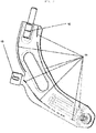
Figure 1 is an exploded view of the swing arm, where one may view each of its components. -
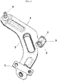
Figure 2 is a side perspective view of the arm indicating where laser welding should take place. -
Figure 3 is a side perspective view of the arm and its already laser welded components. -
Figure 4 is a top perspective view of the arm and its already laser-welded components. - Figure 5 is a perspective view of the cylindrical pin (8) attached to a tube of smaller circular cross-section (7) by laser welding (14).
-
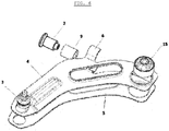
Figure 6 is an exploded view of the suspension arm, in which it is possible to visualize its components, where alternatively, and without changing the laser welding process, a rubber bushing in a vertical form (15), by pressure in the housing on the shaped laser-welded plates (4.5), may also be used in the coupling region, replacing the cylindrical pin (8) fixed to a tube with a smaller circular cross-section (7), and a bushing with fixing flanges (1). -
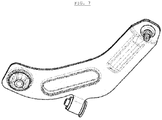
Figure 7 is a side view of the arm and its already laser-welded components, using the alternative form of rubber bushing fixed in the vertical form. -
Figure 8 is a view of the horizontal sectional cut, in which it is possible to see the coupling area between the two formed sheets (4, 5). - With the implementation of the method of the present invention was necessary to change the shape of the product to adapt the necessary requirements for the correct execution of the weld. Thus, there was an increase in the coupling area (10) between the two sheets formed to ensure a smaller empty space between the components. The tube with a smaller circular section (7) was created to intermediate and facilitate the joining process between the pin (8) and the formed sheets (4, 5). The flanged region (6), at one of the ends of the formed plates, which connects to the tube with a larger circular section (9), had its end lengthened so that the device to fix the components by means of welding could make the correct positioning, without there being empty space.
- Alternatively, and without changing the laser welding process, replacing the cylindrical pin (8), fixed to the tube with a smaller circular section (7) and a clamping flange bush (1), a rubber bush fixed in the vertical form (15), fixed by pressure in the already laser welded housing flanges (4, 5) may be used.
- The resulting components of the forming process have dimensional and geometric tolerances that do not always match the requirements for the correct application of the laser welding process. Laser welding, on the other hand, as it is an autogenous joining process, requires a coupling of plates with low permissiveness of empty spaces. Thus, it is necessary to use devices that compensate for the dimensional variations resulting from the forming process so that the joining process is correctly executed. These devices are blocks machined in the nominal form of the part, compressed under the components themselves by high load actuators, forcing them to take the appropriate form for the application of welding, without the presence of voids.
- The suspension arm is composed of two cold formed plates (4, 5), with a flanged region (6) in one of its extremities, a cylindrical pin (8), a tube of smaller circular section (7) wrapped to the aforementioned pin, a tube of larger circular section (9), laser welded (11, 12, 13, 14), used as housing for a rubber bushing (2), a socket joint (3), a cylindrical rubber bushing (2) and a bushing with clamping flanges (1), or optionally in place of the cylindrical pin (8), a smaller circular cross-section tube (7) and a bushing with clamping flanges (1), the vertically clamped rubber bushing (15) can be used in the two already laser-welded shaped plates (4, 5). These components together form the final product, which is connected at two anchor points on the vehicle's crossbar and at one anchor point on the vehicle's baseplate, working in vertical oscillatory movements during its use.
Claims (4)
- Suspension arm clamping procedure consisting of two formed and laser-welded parts characterized by two symmetrical cold formed sheets (4, 5), fixed by laser welding (11) in the coupling region; a cylindrical pin (8), fixed to a tube of smaller circular cross-section (7) by laser welding (14), which in turn is fixed to the symmetrical formed parts by the same process (12); a tube of larger circular cross-section (9), which is also fixed to the two formed parts by laser welding (13), between the tube (9) and a flanged region at one end of the formed part (6).
- Suspension according to claim 1 characterized by being the flanged region (6) of the conformed part that attaches to the tube of larger circular section (9), having its extremity lengthened so that the fixation device of the components, through the laser welding, could make the correct positioning without the presence of empty space.
- Suspension according to claim 1, characterized by being, by the clamping process, a cylindrical pin (8), a smaller circular cross-section tube (7) wrapped around the aforementioned pin, a larger circular cross-section tube (9) used as housing for a cylindrical shaped rubber bushing (2), a socket joint (3), and a bushing with clamping flanges (1).
- Suspension according to claim 1 and 3, characterized by using, alternatively, and without altering the laser welding process, instead of the cylindrical pin (8), fixed in a tube with a smaller circular section (7) and a bushing with fixing flanges (1), a rubber bushing fixed in the vertical form (15), fixed by pressure in housing in the already welded laser plates (4,5).
Applications Claiming Priority (1)
| Application Number | Priority Date | Filing Date | Title |
|---|---|---|---|
| BR102019003079-8A BR102019003079A2 (en) | 2019-02-14 | 2019-02-14 | PROCEDURE FOR FIXING THE SUSPENSION ARM COMPOSED OF TWO CONFORMED AND LASER WELDED PARTS |
Publications (1)
| Publication Number | Publication Date |
|---|---|
| EP3695992A1 true EP3695992A1 (en) | 2020-08-19 |
Family
ID=69172768
Family Applications (1)
| Application Number | Title | Priority Date | Filing Date |
|---|---|---|---|
| EP20152082.2A Withdrawn EP3695992A1 (en) | 2019-02-14 | 2020-01-15 | Control arm clamping process consisting of two shaped and welded laser parts |
Country Status (4)
| Country | Link |
|---|---|
| US (1) | US20200269351A1 (en) |
| EP (1) | EP3695992A1 (en) |
| BR (1) | BR102019003079A2 (en) |
| MX (1) | MX2020001695A (en) |
Cited By (1)
| Publication number | Priority date | Publication date | Assignee | Title |
|---|---|---|---|---|
| CN114260633A (en) * | 2022-01-07 | 2022-04-01 | 武威职业学院 | Rapid splicing welding equipment for irregular workpieces |
Families Citing this family (1)
| Publication number | Priority date | Publication date | Assignee | Title |
|---|---|---|---|---|
| CN116278562B (en) * | 2023-03-21 | 2023-09-15 | 索密克汽车配件有限公司 | Swing arm structure under car suspension and fixed-position welding device thereof |
Citations (5)
| Publication number | Priority date | Publication date | Assignee | Title |
|---|---|---|---|---|
| EP0296568A1 (en) * | 1987-06-26 | 1988-12-28 | FIAT AUTO S.p.A. | Method for assembling the terminal portion of a motor vehicle wheel axle support-member, and the terminal portion produced by this method |
| JPH05112111A (en) * | 1991-10-22 | 1993-05-07 | Yorozu:Kk | Suspension arm for car |
| CN2880561Y (en) * | 2006-02-10 | 2007-03-21 | 上海汇众汽车制造有限公司 | Automobile front under controlling arm |
| CN201665139U (en) * | 2010-01-28 | 2010-12-08 | 上海汇众汽车制造有限公司 | Front lower control arm of automobile |
| FR3064936A1 (en) * | 2017-04-07 | 2018-10-12 | Peugeot Citroen Automobiles Sa | TRIANGLE OR SUSPENSION ARM FOR MOTOR VEHICLE MADE BY HOT STAMPING AND LASER WELDING |
-
2019
- 2019-02-14 BR BR102019003079-8A patent/BR102019003079A2/en not_active IP Right Cessation
-
2020
- 2020-01-15 EP EP20152082.2A patent/EP3695992A1/en not_active Withdrawn
- 2020-01-31 US US16/778,187 patent/US20200269351A1/en not_active Abandoned
- 2020-02-11 MX MX2020001695A patent/MX2020001695A/en unknown
Patent Citations (5)
| Publication number | Priority date | Publication date | Assignee | Title |
|---|---|---|---|---|
| EP0296568A1 (en) * | 1987-06-26 | 1988-12-28 | FIAT AUTO S.p.A. | Method for assembling the terminal portion of a motor vehicle wheel axle support-member, and the terminal portion produced by this method |
| JPH05112111A (en) * | 1991-10-22 | 1993-05-07 | Yorozu:Kk | Suspension arm for car |
| CN2880561Y (en) * | 2006-02-10 | 2007-03-21 | 上海汇众汽车制造有限公司 | Automobile front under controlling arm |
| CN201665139U (en) * | 2010-01-28 | 2010-12-08 | 上海汇众汽车制造有限公司 | Front lower control arm of automobile |
| FR3064936A1 (en) * | 2017-04-07 | 2018-10-12 | Peugeot Citroen Automobiles Sa | TRIANGLE OR SUSPENSION ARM FOR MOTOR VEHICLE MADE BY HOT STAMPING AND LASER WELDING |
Cited By (1)
| Publication number | Priority date | Publication date | Assignee | Title |
|---|---|---|---|---|
| CN114260633A (en) * | 2022-01-07 | 2022-04-01 | 武威职业学院 | Rapid splicing welding equipment for irregular workpieces |
Also Published As
| Publication number | Publication date |
|---|---|
| US20200269351A1 (en) | 2020-08-27 |
| BR102019003079A2 (en) | 2020-09-15 |
| MX2020001695A (en) | 2020-08-20 |
Similar Documents
| Publication | Publication Date | Title |
|---|---|---|
| US8282305B2 (en) | Ball sleeve joint and process for manufacturing same | |
| EP3695992A1 (en) | Control arm clamping process consisting of two shaped and welded laser parts | |
| JP6289649B2 (en) | Compressor and manufacturing method of compressor | |
| US10202012B2 (en) | Suspension link and production method therefor | |
| US12195088B2 (en) | Chassis subframe of a two-track vehicle | |
| US20160281772A1 (en) | Method for manufacture of a chassis module and chassis module manufactured according to such a method | |
| KR20130103857A (en) | Torsion beam axle having ring member friction-welded to trailing arm | |
| AU2015314402A1 (en) | Axle unit | |
| EP1762405B1 (en) | Vehicle suspensions | |
| US7243986B2 (en) | Spot-welded joint for hydroformed members | |
| JP2004338706A (en) | Sub frame for automobile, automobile and method for manufacturing sub frame for automobile | |
| US7281757B2 (en) | Spot-welded joint for hydroformed members | |
| CN115038598B (en) | Multi-point guide arm | |
| EP1208307A1 (en) | Control rod | |
| EP1837098B1 (en) | Manufacturing of a bent axle body with stubs | |
| WO2023120001A1 (en) | Damper | |
| CN210941957U (en) | Connection structure for longitudinal beam of auxiliary frame, auxiliary frame and control arm | |
| JP2002173048A (en) | Body front frame structure and method of connecting vehicle body front frame | |
| US12611902B2 (en) | Suspension structure for vehicle and method of manufacturing the same | |
| CN223833846U (en) | Space pipeline butt joint tool | |
| CN107107693A (en) | Axletree pull bar | |
| JP5747833B2 (en) | Suspension arm | |
| CN219274940U (en) | M16 sub vehicle frame assembly welding jig | |
| CN211308719U (en) | Tubular beam, auxiliary frame and automobile | |
| US20160009154A1 (en) | Suspension member |
Legal Events
| Date | Code | Title | Description |
|---|---|---|---|
| PUAI | Public reference made under article 153(3) epc to a published international application that has entered the european phase |
Free format text: ORIGINAL CODE: 0009012 |
|
| STAA | Information on the status of an ep patent application or granted ep patent |
Free format text: STATUS: THE APPLICATION HAS BEEN PUBLISHED |
|
| AK | Designated contracting states |
Kind code of ref document: A1 Designated state(s): AL AT BE BG CH CY CZ DE DK EE ES FI FR GB GR HR HU IE IS IT LI LT LU LV MC MK MT NL NO PL PT RO RS SE SI SK SM TR |
|
| AX | Request for extension of the european patent |
Extension state: BA ME |
|
| STAA | Information on the status of an ep patent application or granted ep patent |
Free format text: STATUS: REQUEST FOR EXAMINATION WAS MADE |
|
| 17P | Request for examination filed |
Effective date: 20210217 |
|
| RBV | Designated contracting states (corrected) |
Designated state(s): AL AT BE BG CH CY CZ DE DK EE ES FI FR GB GR HR HU IE IS IT LI LT LU LV MC MK MT NL NO PL PT RO RS SE SI SK SM TR |
|
| STAA | Information on the status of an ep patent application or granted ep patent |
Free format text: STATUS: THE APPLICATION IS DEEMED TO BE WITHDRAWN |
|
| 18D | Application deemed to be withdrawn |
Effective date: 20210511 |