EP3695960B1 - Baling press and method of operating a baling press - Google Patents
Baling press and method of operating a baling press Download PDFInfo
- Publication number
- EP3695960B1 EP3695960B1 EP20156698.1A EP20156698A EP3695960B1 EP 3695960 B1 EP3695960 B1 EP 3695960B1 EP 20156698 A EP20156698 A EP 20156698A EP 3695960 B1 EP3695960 B1 EP 3695960B1
- Authority
- EP
- European Patent Office
- Prior art keywords
- feeding chute
- closure
- lock
- baling press
- pressing
- Prior art date
- Legal status (The legal status is an assumption and is not a legal conclusion. Google has not performed a legal analysis and makes no representation as to the accuracy of the status listed.)
- Active
Links
Images


Classifications
-
- B—PERFORMING OPERATIONS; TRANSPORTING
- B30—PRESSES
- B30B—PRESSES IN GENERAL
- B30B9/00—Presses specially adapted for particular purposes
- B30B9/30—Presses specially adapted for particular purposes for baling; Compression boxes therefor
- B30B9/3089—Extrusion presses
-
- B—PERFORMING OPERATIONS; TRANSPORTING
- B30—PRESSES
- B30B—PRESSES IN GENERAL
- B30B15/00—Details of, or accessories for, presses; Auxiliary measures in connection with pressing
- B30B15/28—Arrangements for preventing distortion of, or damage to, presses or parts thereof
-
- B—PERFORMING OPERATIONS; TRANSPORTING
- B30—PRESSES
- B30B—PRESSES IN GENERAL
- B30B9/00—Presses specially adapted for particular purposes
- B30B9/30—Presses specially adapted for particular purposes for baling; Compression boxes therefor
- B30B9/3003—Details
-
- F—MECHANICAL ENGINEERING; LIGHTING; HEATING; WEAPONS; BLASTING
- F16—ENGINEERING ELEMENTS AND UNITS; GENERAL MEASURES FOR PRODUCING AND MAINTAINING EFFECTIVE FUNCTIONING OF MACHINES OR INSTALLATIONS; THERMAL INSULATION IN GENERAL
- F16P—SAFETY DEVICES IN GENERAL; SAFETY DEVICES FOR PRESSES
- F16P3/00—Safety devices acting in conjunction with the control or operation of a machine; Control arrangements requiring the simultaneous use of two or more parts of the body
- F16P3/08—Safety devices acting in conjunction with the control or operation of a machine; Control arrangements requiring the simultaneous use of two or more parts of the body in connection with the locking of doors, covers, guards, or like members giving access to moving machine parts
-
- H—ELECTRICITY
- H01—ELECTRIC ELEMENTS
- H01H—ELECTRIC SWITCHES; RELAYS; SELECTORS; EMERGENCY PROTECTIVE DEVICES
- H01H3/00—Mechanisms for operating contacts
- H01H3/02—Operating parts, i.e. for operating driving mechanism by a mechanical force external to the switch
- H01H3/16—Operating parts, i.e. for operating driving mechanism by a mechanical force external to the switch adapted for actuation at a limit or other predetermined position in the path of a body, the relative movement of switch and body being primarily for a purpose other than the actuation of the switch, e.g. for a door switch, a limit switch, a floor-levelling switch of a lift
- H01H3/161—Operating parts, i.e. for operating driving mechanism by a mechanical force external to the switch adapted for actuation at a limit or other predetermined position in the path of a body, the relative movement of switch and body being primarily for a purpose other than the actuation of the switch, e.g. for a door switch, a limit switch, a floor-levelling switch of a lift for actuation by moving a closing member, e.g. door, cover or lid
-
- H—ELECTRICITY
- H01—ELECTRIC ELEMENTS
- H01H—ELECTRIC SWITCHES; RELAYS; SELECTORS; EMERGENCY PROTECTIVE DEVICES
- H01H9/00—Details of switching devices, not covered by groups H01H1/00 - H01H7/00
- H01H9/20—Interlocking, locking, or latching mechanisms
- H01H9/22—Interlocking, locking, or latching mechanisms for interlocking between casing, cover, or protective shutter and mechanism for operating contacts
- H01H9/226—Interlocking, locking, or latching mechanisms for interlocking between casing, cover, or protective shutter and mechanism for operating contacts the casing containing electrical equipment other than and operated by the switch
Definitions
- the present invention relates to a baling press and to a method of operating a baling press.
- a baling press typically includes a bale pressing channel in which a pressing ram is reciprocally movable to and fro in a pressing chamber, new material to be baled being added each time after the press has been retracted.
- the counter pressure against which the bales are pressed is obtained by resistance encountered by the material as it is pressed through the pressing channel, which, to that end, has a cross-section that decreases in downstream direction over at least a portion of its length.
- Initial counter pressure may be obtained by mounting obstacles in the pressing channel.
- string material is usually tied around the bales.
- the string material is for instance wire or rope material.
- the wire material is for instance steel or plastic wire and the rope material is for instance plastic or natural fiber material that may be twisted or braided and include one or more strands of twisted fiber material.
- a number of loops of the string extending around the bale is usually obtained by feeding strings from two sources along opposite sides of the bale to be formed, tying the strings together near the downstream end of the bale to be formed and tying together the strings near the upstream end of the bale after the material for forming that bale has been pressed.
- a closure in the form of a door or hatch is usually provided in a side wall of the pressing chamber. If a person (or only a portion of a body of a person e.g. an upper body portion) is in the pressing chamber, it is important that the press and the feeding structure are prevented from operating. Unwanted operation of the press while a person is in the pressing chamber can cause injury due to burying the person under material to be pressed or even compressing that person. To avoid such accidents, a safety switch is mounted to the press, which causes power supply to the press to be interrupted when the closure is opened.
- US 5 428 864 A discloses a refuse collecting machine in which a collection hose 14 sucks refuse into a delivery chamber 30 containing a rotating perforated wheel for separating lighter weight refuse from the air flow to a fan, and the refuse then drops into a rotary compression screw to be compressed into a replaceable bag supported at the machine outlet.
- a door 55 Via a door 55, any stuck items can be freed by hand if necessary, and also maintenance and servicing can be carried out.
- the door 55 is controlled by a timer controlled latch so that it cannot be opened until all the rotating parts of the machine have come to a stop after switching off the engine of the machine.
- US 3 608 476 A discloses a baling press according to the pre-characterizing portion of the appended independent claim 1 and a method of operating a baling press according to the pre-characterizing portion of the appended independent claim 7.
- this object is achieved by providing a baling press according to claim 1 and by a method of operating a baling press according to claim 7.
- the closure can only be opened if the feeding chute valve is closed.
- material to be pressed can drop onto a person or a portion of a person in the pressing chamber even though the baling press is cut off from the power supply and thus inactive.
- Material may for instance drop down the feeding chute even though a baling press is inactive, for instance if material has become stuck in the feeding chute but loosens from the feeding chute. Amounts of material dropping down in such a situation can be several thousands of kilograms, which is enough to bury a person or cause severe injury. Also material may just tip over a downstream end of a feeding conveyor. Although such amounts of material are typically smaller, dropping of the material onto a person can still cause injury and is also undesired hygienically.
- the baling press shown in Fig. 1 has a pressing channel 1 in which a ram 2 is displaceable by a hydraulic cylinder 3 mounted between the ram 2 and a suspension bracket 4.
- the ram 2 is shown in its most retracted position.
- a feeding chute 5 communicates with a pressing chamber portion 6 of the pressing channel 1 via a passage 7 forming a downstream end of the feeding chute 5.
- the pressing chamber portion 6 is defined by the stroke volume of a face of the ram 2 facing in pressing direction into the pressing channel 1.
- a feeding chute valve 8 is pivotable about a pivotal axis 9 and has a flat wall 10 which, in the closed position shown, closes off the feeding chute 5 near the pressing channel 1 and, in opened position, is disposed in a wall of the feeding chute 5. If, as in the present example, the feeding chute valve 8 closes off the passage from the feeding chute 5 to the pressing channel at a lower end of the feeding chute 5, there is no section of the feeding chute 5 below the feeding chute valve 8 from which material can still drop into the pressing chamber if the feeding chute valve 8 is closed.
- the prepress valve 8 furthermore has a surface 11 substantially curved around the pivotal axis 9, which surface in closed position bounds the feeding chute 5 in axial direction.
- Material 17 to be pressed may already be deposited into the feeding chute 5, while the prepress valve 8 is closed.
- the prepress valve 8 is opened, all or a portion of the material to be pressed drops into the pressing chamber 6 and may form a pile aside the prepress valve 8.
- the prepress valve 8 is closed again, if a pile has formed aside the prepress valve 8, a volume of the material is precompressed in the pressing chamber 6 by the closing of the prepress valve 8.
- the pressing ram 2 is moved to its most forward position compressing the precompressed material while simultaneously new material to be pressed can be deposited into the feeding chute 5.
- the feeding chute valve may also be in a form that is not suitable for prepressing material in the pressing chamber, for instance in the form of a slide for intermittently closing off and making free the passage from the feeding chute into the pressing chamber portion of the pressing channel.
- the feeding chute valve may also be provided and arranged only for closing off the feeding chute for preventing that material drops down onto personnel working in the pressing chamber.
- the valve may for instance be in the form of a plate or grid and the feeding chute can be provided with a slot and guide for receiving and holding the plate or grid via the slot and supported by the guide in a position extending across the feeding chute, so it is prevented that significant amounts of material can drop into the pressing chamber if the plate or grid is positioned such that it operates the operating member for causing or allowing the lock to be unlocked.
- each bale may be obtained by a single or a plurality of compression cycles of the pressing ram 2 each time compressing material newly fed into the pressing chamber 6.
- Counter pressure in the pressing channel 1 against which a bale is pressed in the pressing chamber 6 and pushed out of the pressing chamber 6 is obtained by resistance encountered by the material of previously compressed material formed into bales 18, 19, 20 as it is pressed through the pressing channel 1 while compressed between top and bottom walls 12, 13 and side walls of the pressing channel 1.
- the pressing channel 1 may for instance have a cross-section that decreases in downstream direction over at least a portion of its length and/or one or more walls of at least a downstream portion of the pressing channel may resiliently be pressed inwardly.
- Initial counter pressure may be obtained by mounting obstacles in the pressing channel 1 that are pressed out by the first bale.
- loops 21, 22 of string material are tied around each bale 18-20.
- the string material may for instance be wire or rope material.
- the wire material may for instance be steel or plastic wire and the rope material may for instance be plastic or natural fiber material that may be twisted or braided and include one or more strands of twisted fiber material.
- the string material is wire material that is tied by twisting.
- other string material and other manners of connecting such as knotting, welding or use of fasteners, can also be applied.
- each first wire 24 fed from below has been tied, by means of a twist 46, to an upper wire 26 fed from above during the tying of a previous bale.
- a tying assembly is provided for arranging a loop of wire material 24, 25 around a bale and for holding a pair of end portions of the loop next to each other.
- the tying assembly includes lower guide rollers 30, 31 located closely along the bottom of the pressing channel 1, for guiding lower wires 24 fed from respective spools (not shown) into the pressing channel 1 and loop supply members for pulling up lower wires 24 from adjacent to the bottom of the bale pressing channel 1.
- the loop supply members are in the form of rods reciprocally movable in longitudinal direction of the rods and are suspended in positions on a first, upper side of the bale pressing channel 1 and in pressing direction of the feed passage 7 and each have a hook adjacent to a free end for catching the lower wires 24 on a second, lower side of the bale pressing channel 1 and for catching the upper wire on the upper side of the bale pressing channel 1.
- the loop supply members are movable between an extended, lowermost position as indicated by dash and dot lines in Fig. 1 and a retracted, uppermost position as shown in full lines in Fig. 1 . In the retracted position, the loop supply members are on the upper side of the bale pressing channel.
- the loop supply members are extended through passages 27 in an upper wall 12 of the pressing channel 1 and through slots (not shown) in the pressing ram 3, catch the lower wires 24 that extend closely along the bottom of the pressing channel 1 and pull up loops of the wires 24 to form temporary loops projecting above the pressing channel 1.
- the loop supply members also catch and entrain the upper wires 25 into temporary loops so that the temporary loops of upper and lower wire material 24, 25 commonly extend along the loop supply members.
- first side is the upper side of the bale pressing channel and the second side is the lower side of the bale pressing channel
- first and second sides may also be opposite lateral sides of the bale pressing channel or upper and lower sides may be reversed.
- connectors in the form of twisters are arranged for engaging the pairs of end portions near the bale and moving an engaged section of at least one of each of the pairs of end portions about a longitudinal axis of the other such that the pairs of end portions are twisted into wire twists 40 between the twisters and the respective portions of the loops extending about the bale 20.
- a second set of connectors in the form of twisters is provided for engaging pairs of end portions of the wires 24, 25 extending to the twisters from the respective supply spools and moving engaged sections of the end portions about longitudinal axes of the other section of each pair such that the end portions are also twisted into wire twists between the twisters and more remote sections of the upper and lower wires 24, 25.
- These twists 46 connect the respective upper and lower wires 24, 25 to each other, such that when a new bale is pressed out of the pressing chamber 6, the upper and lower wires 24, 25 are pulled around the bale and form the downstream portions of the new loops being formed around that bale.
- the wires 24, 25 are cut between the respective loop supply members by a cutter.
- wire guiding rollers 31, 32 are mounted to the walls 12, 13.
- the baling press further has a closure 23 movable between an open and a closed position.
- the closure 23 closes off an opening in a wall of the pressing chamber 6 when in a closed position and allows a person to at least partially access the pressing chamber 6 via the opening when in an open position.
- a lock 21 with a bolt 22 for locking the closure 23 is mounted to a wall of the baling press near the opening and the closure 23.
- the lock 21 is operable for unlocking the closure 23 by moving the bolt 22 from a locking position 22 to a non-locking position 22' (see Fig. 3 ).
- An operating member 35 is arranged for being operated when the prepress valve 8 is in the closed position.
- the operating member 35 is coupled to the lock 21 for unlocking of the lock 21 only if the operating member 35 is operated by the prepress valve 8 in or near its closed position.
- the closure can only be opened if the prepress valve is closed or almost closed.
- material to be pressed can drop onto a person or a portion of a person in the pressing chamber 6 even though the baling press is cut off from the power supply and thus inactive.
- Material may for instance drop down the feeding chute 5 even though a baling press is inactive, for instance if material has become stuck in the feeding chute 5 but loosens from the feeding chute 5.
- the lock only unlocks the closure if the prepress valve is fully closed. However, it may also be advantageous if the lock also unlocks the closure if the prepress valve is nearly closed. If the prepress valve is opened by less than 10% and in particular if it is opened by less than 5%, relatively little risk is associated with material dropping through the small percentage of the surface area of the feeding chute cross-sectional area that is left open by the prepress valve.
- the operating member 35 and the lock 21 must operate also if there is no power supply to the baling press. This can be achieved in a reliable manner if, as in the example shown in Figs. 2 and 3 , the operating member 35 is provided with a hydraulic or pneumatic master cylinder 36 and the lock 21 includes a slave cylinder 37 coupled to the bolt 22 for moving the bolt 22 between a locked and an unlocked position.
- the master cylinder 36 and the slave cylinder 37 communicate via a hydraulic or pneumatic conduit 38.
- the lock 21 is provided with a spring 39 that urges the bolt 22 into its closed position. If the prepress valve 8 is closed, a projection 41 presses a piston of the master cylinder 36 into a housing 42 of the master cylinder 36. This causes fluid to be pressed into the conduit 38, so that a piston 43 of the slave cylinder 37 is pressed out of a housing 44 of the slave cylinder 37. This displacement of the piston 43 of the slave cylinder 37 causes the bolt 22 to be pressed towards an unlocking position 22' against a pulling force exerted by the spring 39.
- the conduit 38 preferably extends through a flexible hose or tube, so that relative positions of the operating member and the lock can be selected freely within a range sufficiently large to allow the safety system to be mounted to a variety of baling presses. This is particularly advantageous for backward compatibility with installed baling presses.
- the lock 21 is arranged for being unlocked by means of a key that allows opening of the housing 45 of the lock 21, independently of the position of the prepress valve 8. Once the housing has been removed, the bolt can be operated directly by means of a handle portion 48 of the bolt 22.
- Such a key can for instance be kept by a supervising person, to ensure that the pressing chamber 6 is only accessed while the prepress valve is open when particular safety precautions are observed, such as inspection of the feeding chute 5 for stuck material, arranging a shield in the pressing chamber and/or only accessing the pressing chamber by means of tools while no body parts of personnel enter the pressing chamber.
- the coupling between the prepress valve operated operating member and the lock may also be provided in many other forms, such as mechanical, electrical and optical.
- the lock may be powered by the operating member or the operating member may only provide a signal causing or allowing the lock to be operated for releasing the closure. If the coupling is only for communication of a signal from the operating member to the lock, such communication may be direct or via a bus system operating also if the main power supply of the baling press is off.
- the coupling may be wired or wireless.
- FIG. 4 An example of a mechanical coupling is shown in Fig. 4 .
- a mechanical coupling 138 of the operating member 135 and the lock 121 allows a particularly simple and low cost solution to be applied.
- a projection 141 projecting from the prepress valve 8 displaces an operating member 135 if the prepress valve 8 is closed. The displacement is transferred via a connecting rod 138 to a lever type bolt 122 of the lock 121 and causes the closure 23 to be unlocked.
- a force exerted by a spring 139 urges the operating member 135, the lock 121 and the connection rod 138 back, so that the closure 23 is locked again.
- the mechanical connection is a flexible Bowden cable
- relative positions of the operating member and the lock can be selected freely within a range sufficiently large to allow the safety system to be mounted to a variety of baling presses. This is particularly advantageous for backward compatibility with installed baling presses.
- the Bowden cable is preferably a push-pull Bowden cable, but may also be a pull Bowden cable co-operating with a spring member for causing the lock to run back when the operating member is not operated by the prepress valve in or near its closed position.
- the operating member 235 may also include an electric switch 236 that is closed or opened in response to the prepress valve 8 reaching or approaching the closed position.
- the switch may for instance be operated by a switch engagement surface 241 of the prepress valve 8.
- the lock 221 includes an electric actuator 237 for unlocking the lock 221 in response to a voltage corresponding to a condition of the prepress valve 8 that occurs if the prepress valve 8 is in or near the closed position.
- the electric switch 236 is included in a circuit having a secondary power supply 259 for providing a voltage independently of a power supply 258 of the baling press, so that the electric unlocking can operate also if the main power supply 258 is switched off for allowing the closure 23 to be opened.
- Diodes 260, 261 are provided for allowing power to be supplied alternatively by either of the power supplies 258, 259.
- the switch 236 is arranged for opening if the prepress valve 8 is closed, the actuator 237 is for unlocking if no voltage is applied and the main power supply 258 and the secondary power supply 259 are connected in parallel, the system ensures that the closure is unlocked only if the main power supply of the baling press is switched off and the prepress valve 8 is closed. Thus, a separate switch for cutting off baling press power would not be needed or an additional safeguard against opening of the closure 23 without switching off of the main power supply is obtained.
Landscapes
- Engineering & Computer Science (AREA)
- Mechanical Engineering (AREA)
- General Engineering & Computer Science (AREA)
- Computer Security & Cryptography (AREA)
- Press Drives And Press Lines (AREA)
Description
- The present invention relates to a baling press and to a method of operating a baling press.
- To facilitate storage, handling and transportation of loose material, such as waste paper and cardboard, waste plastic, garbage waste, straw, it is usual to press the material into bales.
- To prepare the bales, the material is compressed in a baling press. A baling press typically includes a bale pressing channel in which a pressing ram is reciprocally movable to and fro in a pressing chamber, new material to be baled being added each time after the press has been retracted. The counter pressure against which the bales are pressed is obtained by resistance encountered by the material as it is pressed through the pressing channel, which, to that end, has a cross-section that decreases in downstream direction over at least a portion of its length. Initial counter pressure may be obtained by mounting obstacles in the pressing channel.
- For facilitating separation of the pressed material into distinct bales and for keeping the bales together, string material is usually tied around the bales. The string material is for instance wire or rope material. The wire material is for instance steel or plastic wire and the rope material is for instance plastic or natural fiber material that may be twisted or braided and include one or more strands of twisted fiber material. A number of loops of the string extending around the bale is usually obtained by feeding strings from two sources along opposite sides of the bale to be formed, tying the strings together near the downstream end of the bale to be formed and tying together the strings near the upstream end of the bale after the material for forming that bale has been pressed.
- It sometimes occurs that operators have to enter the pressing chamber for solving problems such as threading in and tying up string material after it has broken or removing material that blocks the pressing ram.
- To allow persons to enter the pressing chamber, a closure in the form of a door or hatch is usually provided in a side wall of the pressing chamber. If a person (or only a portion of a body of a person e.g. an upper body portion) is in the pressing chamber, it is important that the press and the feeding structure are prevented from operating. Unwanted operation of the press while a person is in the pressing chamber can cause injury due to burying the person under material to be pressed or even compressing that person. To avoid such accidents, a safety switch is mounted to the press, which causes power supply to the press to be interrupted when the closure is opened.
- It is noted that
US 5 428 864 A discloses a refuse collecting machine in which a collection hose 14 sucks refuse into adelivery chamber 30 containing a rotating perforated wheel for separating lighter weight refuse from the air flow to a fan, and the refuse then drops into a rotary compression screw to be compressed into a replaceable bag supported at the machine outlet. Via a door 55, any stuck items can be freed by hand if necessary, and also maintenance and servicing can be carried out. The door 55 is controlled by a timer controlled latch so that it cannot be opened until all the rotating parts of the machine have come to a stop after switching off the engine of the machine. - It is further noted that
US 3 608 476 A discloses a baling press according to the pre-characterizing portion of the appended independent claim 1 and a method of operating a baling press according to the pre-characterizing portion of the appended independent claim 7. - It is an object of the present invention to provide a solution that further increases safety for a person who completely or partially enters or has entered the pressing chamber via the opening that is closeable by the closure.
- According to the invention, this object is achieved by providing a baling press according to claim 1 and by a method of operating a baling press according to claim 7.
- Because the lock is operated by the operating member for unlocking the closure or allowing unlocking of the closure only if the operating member is operated by the feeding chute valve in or near its closed position, the closure can only be opened if the feeding chute valve is closed. Thus it is avoided that material to be pressed can drop onto a person or a portion of a person in the pressing chamber even though the baling press is cut off from the power supply and thus inactive. Material may for instance drop down the feeding chute even though a baling press is inactive, for instance if material has become stuck in the feeding chute but loosens from the feeding chute. Amounts of material dropping down in such a situation can be several thousands of kilograms, which is enough to bury a person or cause severe injury. Also material may just tip over a downstream end of a feeding conveyor. Although such amounts of material are typically smaller, dropping of the material onto a person can still cause injury and is also undesired hygienically.
- Particular elaborations and embodiments of the invention are set forth in the dependent claims.
- Further features, effects and details of the invention appear from the detailed description and the drawings.
-
-
Fig. 1 is a schematic, partially cut-away side view of an example of a baling press according to the invention; -
Fig. 2 is a schematic, partially cut-away side view of an operating member of a first example of a baling press according to the invention; -
Fig. 3 is a schematic, partially cut-away side view of a lock of a first example of a baling press according to the invention; -
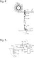
Fig. 4 is a schematic side view of an operating member and a lock coupled thereto of a second example of a baling press according to the invention; and -
Fig. 5 is a schematic side view of an operating member and a lock coupled thereto of a third example of a baling press according to the invention. - The baling press shown in
Fig. 1 has a pressing channel 1 in which a ram 2 is displaceable by a hydraulic cylinder 3 mounted between the ram 2 and asuspension bracket 4. The ram 2 is shown in its most retracted position. Afeeding chute 5 communicates with a pressing chamber portion 6 of the pressing channel 1 via a passage 7 forming a downstream end of thefeeding chute 5. The pressing chamber portion 6 is defined by the stroke volume of a face of the ram 2 facing in pressing direction into the pressing channel 1. - A
feeding chute valve 8 is pivotable about a pivotal axis 9 and has a flat wall 10 which, in the closed position shown, closes off thefeeding chute 5 near the pressing channel 1 and, in opened position, is disposed in a wall of thefeeding chute 5. If, as in the present example, thefeeding chute valve 8 closes off the passage from thefeeding chute 5 to the pressing channel at a lower end of thefeeding chute 5, there is no section of thefeeding chute 5 below thefeeding chute valve 8 from which material can still drop into the pressing chamber if thefeeding chute valve 8 is closed. The prepressvalve 8 furthermore has asurface 11 substantially curved around the pivotal axis 9, which surface in closed position bounds thefeeding chute 5 in axial direction. -
Material 17 to be pressed may already be deposited into thefeeding chute 5, while theprepress valve 8 is closed. When the prepressvalve 8 is opened, all or a portion of the material to be pressed drops into the pressing chamber 6 and may form a pile aside the prepressvalve 8. When the prepressvalve 8 is closed again, if a pile has formed aside the prepressvalve 8, a volume of the material is precompressed in the pressing chamber 6 by the closing of the prepressvalve 8. Next, the pressing ram 2 is moved to its most forward position compressing the precompressed material while simultaneously new material to be pressed can be deposited into thefeeding chute 5. - The feeding chute valve may also be in a form that is not suitable for prepressing material in the pressing chamber, for instance in the form of a slide for intermittently closing off and making free the passage from the feeding chute into the pressing chamber portion of the pressing channel. Although it is advantageous if the feeding chute valve is also provided and arranged for closing off the feeding chute during pressing by the pressing ram when the baling press is in normal operation, the feeding chute valve may also be provided and arranged only for closing off the feeding chute for preventing that material drops down onto personnel working in the pressing chamber. To that end, the valve may for instance be in the form of a plate or grid and the feeding chute can be provided with a slot and guide for receiving and holding the plate or grid via the slot and supported by the guide in a position extending across the feeding chute, so it is prevented that significant amounts of material can drop into the pressing chamber if the plate or grid is positioned such that it operates the operating member for causing or allowing the lock to be unlocked.
- Depending on the compressibility of the
material 17, compressing of a volume of material for forming a bale 18-20 may require several cycles of retracting the ram 2 in a direction opposite to the pressing direction, feeding material with the prepressvalve 8 open, closing the prepressvalve 8 while optionally prepressing and compressing by advancing the ram in pressing direction. Thus, each bale may be obtained by a single or a plurality of compression cycles of the pressing ram 2 each time compressing material newly fed into the pressing chamber 6. - Counter pressure in the pressing channel 1 against which a bale is pressed in the pressing chamber 6 and pushed out of the pressing chamber 6 is obtained by resistance encountered by the material of previously compressed material formed into
bales bottom walls - For facilitating separation of compressed material into discrete bales and for facilitating manipulation, transport and for preventing bales from falling apart,
loops - For tying one or more loops of wire material around each bale, one or more (in this example five)
lower wires 24 are fed under pressing channel 1. From above, the same number ofwires 25 is fed. Before a bale is formed, eachfirst wire 24 fed from below has been tied, by means of atwist 46, to an upper wire 26 fed from above during the tying of a previous bale. - A tying assembly is provided for arranging a loop of
wire material lower guide rollers 30, 31 located closely along the bottom of the pressing channel 1, for guidinglower wires 24 fed from respective spools (not shown) into the pressing channel 1 and loop supply members for pulling uplower wires 24 from adjacent to the bottom of the bale pressing channel 1. The loop supply members are in the form of rods reciprocally movable in longitudinal direction of the rods and are suspended in positions on a first, upper side of the bale pressing channel 1 and in pressing direction of the feed passage 7 and each have a hook adjacent to a free end for catching thelower wires 24 on a second, lower side of the bale pressing channel 1 and for catching the upper wire on the upper side of the bale pressing channel 1. The loop supply members are movable between an extended, lowermost position as indicated by dash and dot lines inFig. 1 and a retracted, uppermost position as shown in full lines inFig. 1 . In the retracted position, the loop supply members are on the upper side of the bale pressing channel. Each time after a bale is pushed out of the pressing chamber 6, the loop supply members are extended throughpassages 27 in anupper wall 12 of the pressing channel 1 and through slots (not shown) in the pressing ram 3, catch thelower wires 24 that extend closely along the bottom of the pressing channel 1 and pull up loops of thewires 24 to form temporary loops projecting above the pressing channel 1. During a last portion of the upward movement, the loop supply members also catch and entrain theupper wires 25 into temporary loops so that the temporary loops of upper andlower wire material - While in the present example, the first side is the upper side of the bale pressing channel and the second side is the lower side of the bale pressing channel, the first and second sides may also be opposite lateral sides of the bale pressing channel or upper and lower sides may be reversed.
- For connecting end portions of the loops of
wires bale 20 to each other, connectors in the form of twisters are arranged for engaging the pairs of end portions near the bale and moving an engaged section of at least one of each of the pairs of end portions about a longitudinal axis of the other such that the pairs of end portions are twisted into wire twists 40 between the twisters and the respective portions of the loops extending about thebale 20. - Furthermore, a second set of connectors in the form of twisters is provided for engaging pairs of end portions of the
wires lower wires twists 46 connect the respective upper andlower wires lower wires - After the
twists wires - In the present example
wire guiding rollers 31, 32 are mounted to thewalls - The baling press further has a
closure 23 movable between an open and a closed position. Theclosure 23 closes off an opening in a wall of the pressing chamber 6 when in a closed position and allows a person to at least partially access the pressing chamber 6 via the opening when in an open position. - To a wall of the baling press near the opening and the
closure 23, alock 21 with abolt 22 for locking theclosure 23 is mounted. Thelock 21 is operable for unlocking theclosure 23 by moving thebolt 22 from a lockingposition 22 to a non-locking position 22' (seeFig. 3 ). - An operating
member 35 is arranged for being operated when theprepress valve 8 is in the closed position. The operatingmember 35 is coupled to thelock 21 for unlocking of thelock 21 only if the operatingmember 35 is operated by theprepress valve 8 in or near its closed position. - Because the
lock 21 is operated by the operatingmember 35 for unlocking theclosure 23 only if the operatingmember 35 is operated by theprepress valve 8 in or near its closed position, the closure can only be opened if the prepress valve is closed or almost closed. Thus it is avoided that material to be pressed can drop onto a person or a portion of a person in the pressing chamber 6 even though the baling press is cut off from the power supply and thus inactive. Material may for instance drop down the feedingchute 5 even though a baling press is inactive, for instance if material has become stuck in thefeeding chute 5 but loosens from the feedingchute 5. - Preferably, the lock only unlocks the closure if the prepress valve is fully closed. However, it may also be advantageous if the lock also unlocks the closure if the prepress valve is nearly closed. If the prepress valve is opened by less than 10% and in particular if it is opened by less than 5%, relatively little risk is associated with material dropping through the small percentage of the surface area of the feeding chute cross-sectional area that is left open by the prepress valve.
- Because the
closure 23 is also provided with a switch that cuts off power supply from the baling press if the closure is opened or requires the power supply to be cut off if theclosure 23 is to be opened, the operatingmember 35 and thelock 21 must operate also if there is no power supply to the baling press. This can be achieved in a reliable manner if, as in the example shown inFigs. 2 and 3 , the operatingmember 35 is provided with a hydraulic orpneumatic master cylinder 36 and thelock 21 includes aslave cylinder 37 coupled to thebolt 22 for moving thebolt 22 between a locked and an unlocked position. Themaster cylinder 36 and theslave cylinder 37 communicate via a hydraulic orpneumatic conduit 38. - To ensure safe operation, the
lock 21 is provided with aspring 39 that urges thebolt 22 into its closed position. If theprepress valve 8 is closed, aprojection 41 presses a piston of themaster cylinder 36 into ahousing 42 of themaster cylinder 36. This causes fluid to be pressed into theconduit 38, so that apiston 43 of theslave cylinder 37 is pressed out of a housing 44 of theslave cylinder 37. This displacement of thepiston 43 of theslave cylinder 37 causes thebolt 22 to be pressed towards an unlocking position 22' against a pulling force exerted by thespring 39. - When the
prepress valve 8 closes again, thepiston 43 of themaster cylinder 36 is allowed to move out of thehousing 42 of themaster cylinder 36 again. Then, the force exerted by thespring 39 causes thepiston 43 of theslave cylinder 37 to be pressed back into the housing 44 of theslave cylinder 37, the displacement of fluid through theconduit 38 causing thepiston 43 of themaster cylinder 36 to move out of thehousing 42 of themaster cylinder 36 again. - The
conduit 38 preferably extends through a flexible hose or tube, so that relative positions of the operating member and the lock can be selected freely within a range sufficiently large to allow the safety system to be mounted to a variety of baling presses. This is particularly advantageous for backward compatibility with installed baling presses. - In some special situations, access to the pressing chamber is required even though the prepress valve is open or partially open. While the safety system shown in
Figs. 2 and 3 prevents such access as a routine procedure, thelock 21 is arranged for being unlocked by means of a key that allows opening of thehousing 45 of thelock 21, independently of the position of theprepress valve 8. Once the housing has been removed, the bolt can be operated directly by means of ahandle portion 48 of thebolt 22. Such a key can for instance be kept by a supervising person, to ensure that the pressing chamber 6 is only accessed while the prepress valve is open when particular safety precautions are observed, such as inspection of the feedingchute 5 for stuck material, arranging a shield in the pressing chamber and/or only accessing the pressing chamber by means of tools while no body parts of personnel enter the pressing chamber. - The coupling between the prepress valve operated operating member and the lock may also be provided in many other forms, such as mechanical, electrical and optical. The lock may be powered by the operating member or the operating member may only provide a signal causing or allowing the lock to be operated for releasing the closure. If the coupling is only for communication of a signal from the operating member to the lock, such communication may be direct or via a bus system operating also if the main power supply of the baling press is off. The coupling may be wired or wireless.
- An example of a mechanical coupling is shown in
Fig. 4 . Amechanical coupling 138 of the operatingmember 135 and thelock 121 allows a particularly simple and low cost solution to be applied. In this example a projection 141 projecting from theprepress valve 8 displaces an operatingmember 135 if theprepress valve 8 is closed. The displacement is transferred via a connectingrod 138 to alever type bolt 122 of thelock 121 and causes theclosure 23 to be unlocked. When theprepress valve 8 opens again, a force exerted by aspring 139 urges the operatingmember 135, thelock 121 and theconnection rod 138 back, so that theclosure 23 is locked again. - If the mechanical connection is a flexible Bowden cable, relative positions of the operating member and the lock can be selected freely within a range sufficiently large to allow the safety system to be mounted to a variety of baling presses. This is particularly advantageous for backward compatibility with installed baling presses. The Bowden cable is preferably a push-pull Bowden cable, but may also be a pull Bowden cable co-operating with a spring member for causing the lock to run back when the operating member is not operated by the prepress valve in or near its closed position.
- As is illustrated by
Fig. 5 , the operatingmember 235 may also include anelectric switch 236 that is closed or opened in response to theprepress valve 8 reaching or approaching the closed position. The switch may for instance be operated by aswitch engagement surface 241 of theprepress valve 8. Thelock 221 includes anelectric actuator 237 for unlocking thelock 221 in response to a voltage corresponding to a condition of theprepress valve 8 that occurs if theprepress valve 8 is in or near the closed position. Theelectric switch 236 is included in a circuit having asecondary power supply 259 for providing a voltage independently of apower supply 258 of the baling press, so that the electric unlocking can operate also if themain power supply 258 is switched off for allowing theclosure 23 to be opened.Diodes - If the
switch 236 is arranged for opening if theprepress valve 8 is closed, theactuator 237 is for unlocking if no voltage is applied and themain power supply 258 and thesecondary power supply 259 are connected in parallel, the system ensures that the closure is unlocked only if the main power supply of the baling press is switched off and theprepress valve 8 is closed. Thus, a separate switch for cutting off baling press power would not be needed or an additional safeguard against opening of theclosure 23 without switching off of the main power supply is obtained. - Several features have been described as part of the same or separate embodiments. However, it will be appreciated that the scope of the invention as defined by the appended claims also includes embodiments having combinations of all or some of these features other than the specific combinations of features embodied in the examples.
Claims (7)
- A baling press comprising:a bale pressing channel (1);a ram (2) reciprocally movable in a pressing chamber (6) portion of the bale pressing channel (1) for pressing material in the bale pressing channel;a feeding chute (5) communicating with the pressing chamber (6) via a feed passage (7) forming a downstream end of the feeding chute;a feeding chute valve (8) which, in closed position, closes off the feeding chute (5) near the pressing channel (1); anda closure (23) movable between an open and a closed position, the closure closing off an opening in a wall of the pressing chamber (6) when the closure (23) is in a closed position and allowing a person to at least partially access the pressing chamber (6) via the opening when the closure (23) is in an open position;characterized by:a lock (21; 121; 221) with a bolt (22; 122) movable for locking and unlocking the closure (23), said lock (21; 121; 221) being operable for unlocking the closure (23); andan operating member (35; 135; 235) arranged for being operated by the feeding chute valve (8) when the feeding chute valve (8) is in the closed position, said operating member (35; 135; 235) being coupled to the lock (21; 121; 221) for unlocking or allowing unlocking of the lock (21; 121; 221) only if the operating member (35; 135; 235) is operated by the feeding chute valve (8) in or near its closed position.
- A baling press according to claim 1, wherein the operating member (35) comprises a hydraulic or pneumatic master cylinder (36) and wherein the lock (21) includes a slave cylinder (37) coupled to the bolt (22) for moving the bolt between a locked and an unlocked position, the master cylinder and the slave cylinder communicating via a hydraulic or pneumatic conduit (38).
- A baling press according to claim 1, wherein the operating member (135) and the lock (121) are mechanically coupled.
- A baling press according to claim 3, wherein the mechanical coupling is a flexible Bowden cable.
- A baling press according to claim 1, wherein the operating member (235) includes an electric switch (236) that is closed or opened in response to the feeding chute valve (8) reaching or approaching the closed position, wherein the lock (221) includes an electric actuator (237) for unlocking the lock in response to a voltage corresponding to a condition of the switch if the feeding chute valve (8) is in or near the closed position, the electric switch be included in a circuit having a power supply (259) for providing a voltage independently of a power supply (258) of the baling press.
- A baling press according to any of the preceding claims, wherein the lock (21) is arranged for being unlocked or accessible for unlocking by means of a key, independently of the position of the feeding chute valve (8).
- A method of operating a baling press, the baling press comprising:a bale pressing channel (1);a ram (2) reciprocally movable in a pressing chamber (6) portion of the bale pressing channel (1) for pressing material in the bale pressing channel (1);a feeding chute (5) communicating with the pressing chamber (6) via a feed passage (7) forming a downstream end of the feeding chute;a feeding chute valve (8) which, in closed position, closes off the feeding chute (5) near the pressing channel (1); anda closure (23) movable between an open and a closed position, the closure (23) closing off an opening in a wall of the pressing chamber when the closure (23) is in a closed position and allowing a person to at least partially access the pressing chamber (6) via the opening when the closure (23) is in an open position;characterized in that the baling press further comprises:a lock (21; 121; 221) with a bolt (22; 122) movable for locking the closure (23) and unlocking the closure (23); andan operating member (35; 135; 235) coupled to the lock (21; 121; 221);wherein the lock (21; 121; 221) is operated by the operating member (35; 135; 235) for unlocking or allowing unlocking of the closure (23) only if the operating member (35; 135; 235) is operated by the feeding chute valve (8) in or near its closed position.
Applications Claiming Priority (1)
| Application Number | Priority Date | Filing Date | Title |
|---|---|---|---|
| NL2022562A NL2022562B1 (en) | 2019-02-12 | 2019-02-12 | Baling press and method of operating a baling press |
Publications (3)
| Publication Number | Publication Date |
|---|---|
| EP3695960A1 EP3695960A1 (en) | 2020-08-19 |
| EP3695960C0 EP3695960C0 (en) | 2023-06-07 |
| EP3695960B1 true EP3695960B1 (en) | 2023-06-07 |
Family
ID=67262972
Family Applications (1)
| Application Number | Title | Priority Date | Filing Date |
|---|---|---|---|
| EP20156698.1A Active EP3695960B1 (en) | 2019-02-12 | 2020-02-11 | Baling press and method of operating a baling press |
Country Status (2)
| Country | Link |
|---|---|
| EP (1) | EP3695960B1 (en) |
| NL (1) | NL2022562B1 (en) |
Families Citing this family (1)
| Publication number | Priority date | Publication date | Assignee | Title |
|---|---|---|---|---|
| KR102288598B1 (en) * | 2021-03-17 | 2021-08-10 | 권진상 | Binding device for compressed waste paper using wire |
Family Cites Families (9)
| Publication number | Priority date | Publication date | Assignee | Title |
|---|---|---|---|---|
| US3608476A (en) * | 1969-06-27 | 1971-09-28 | Int Patents & Dev Corp | Garbage compactor |
| US3762311A (en) * | 1971-05-17 | 1973-10-02 | Friedman | Tamper for baler |
| US3855918A (en) * | 1973-01-22 | 1974-12-24 | B Trajbar | Refuse compactor |
| DE2815300A1 (en) * | 1978-04-08 | 1979-10-18 | Schwelling Maschbau Hermann | Double action operating element for limit switches - has hinge pin of scrap press filling door with two cams on which pin of limit switch rests |
| GB9123492D0 (en) * | 1991-11-05 | 1991-12-18 | Pemberton Peter | Refuse collecting apparatus |
| ITMI20051381A1 (en) * | 2005-07-20 | 2007-01-21 | Ecoassistenza S R L | SAFETY DEVICE FOR A FEEDING TAPE AND A PRESS INTENDED FOR THE COMPRESSION OF WASTE |
| US7690402B2 (en) * | 2005-09-11 | 2010-04-06 | Machinefabriek Bollegraaf Appingedam B.V. | Method, an implement and a twister for tying together end portions of wire material extending around a bale |
| US7690297B1 (en) * | 2008-09-22 | 2010-04-06 | Harmony Enterprises, Inc. | Baler tie feed apparatus |
| CN108438659A (en) * | 2018-05-22 | 2018-08-24 | 厦门市鲲龙贸易有限公司 | Integrally closed garbage compression box |
-
2019
- 2019-02-12 NL NL2022562A patent/NL2022562B1/en active
-
2020
- 2020-02-11 EP EP20156698.1A patent/EP3695960B1/en active Active
Also Published As
| Publication number | Publication date |
|---|---|
| EP3695960C0 (en) | 2023-06-07 |
| EP3695960A1 (en) | 2020-08-19 |
| NL2022562B1 (en) | 2020-08-27 |
Similar Documents
| Publication | Publication Date | Title |
|---|---|---|
| US10266289B2 (en) | Method for removing a twist-module sub-assembly in a knotter assembly | |
| US7690297B1 (en) | Baler tie feed apparatus | |
| EP2941951B1 (en) | Baling press with a rope tying system and method of supplying rope to a knotter of a baling press | |
| EP3695960A1 (en) | Baling press and method of operating a baling press | |
| CN211109840U (en) | Full-automatic unpacking and feeding machine for stacked bagged raw materials | |
| DE2857815C2 (en) | Harvester | |
| AU2012302002B2 (en) | Knotter assembly | |
| KR20200095720A (en) | Automatic equipment for put fruit in a paper bag | |
| DE2749485A1 (en) | HARVEST BALER | |
| US10654236B2 (en) | Baling press and method of pressing and tying bales in a baling press | |
| DE3617155C2 (en) | ||
| CN104053354B (en) | A safe knotter for an agricultural baler | |
| US3327620A (en) | Packer | |
| US7690402B2 (en) | Method, an implement and a twister for tying together end portions of wire material extending around a bale | |
| US7493854B2 (en) | Jam detection and safety device for jamming machinery | |
| DE2656699A1 (en) | WASTE HANDLING PROCEDURES | |
| EP1785351A1 (en) | A method, an implement and a twister for tying together end portions of wire material extending around a bale | |
| EP4261028B1 (en) | Cross-bucked channel baling press | |
| DE3448516C2 (en) | Bale press for compressing materials such as paper waste or the like into bales | |
| DE202013012192U1 (en) | Baler | |
| KR101407613B1 (en) | String-binding apparatus for waste paper compressor | |
| CN107667006B (en) | Filling device and filling method | |
| US4403543A (en) | Baling device | |
| CN111391388A (en) | Double-pressure-head packer | |
| US711480A (en) | Baling-press. |
Legal Events
| Date | Code | Title | Description |
|---|---|---|---|
| PUAI | Public reference made under article 153(3) epc to a published international application that has entered the european phase |
Free format text: ORIGINAL CODE: 0009012 |
|
| STAA | Information on the status of an ep patent application or granted ep patent |
Free format text: STATUS: THE APPLICATION HAS BEEN PUBLISHED |
|
| AK | Designated contracting states |
Kind code of ref document: A1 Designated state(s): AL AT BE BG CH CY CZ DE DK EE ES FI FR GB GR HR HU IE IS IT LI LT LU LV MC MK MT NL NO PL PT RO RS SE SI SK SM TR |
|
| AX | Request for extension of the european patent |
Extension state: BA ME |
|
| STAA | Information on the status of an ep patent application or granted ep patent |
Free format text: STATUS: REQUEST FOR EXAMINATION WAS MADE |
|
| 17P | Request for examination filed |
Effective date: 20210118 |
|
| RBV | Designated contracting states (corrected) |
Designated state(s): AL AT BE BG CH CY CZ DE DK EE ES FI FR GB GR HR HU IE IS IT LI LT LU LV MC MK MT NL NO PL PT RO RS SE SI SK SM TR |
|
| GRAP | Despatch of communication of intention to grant a patent |
Free format text: ORIGINAL CODE: EPIDOSNIGR1 |
|
| STAA | Information on the status of an ep patent application or granted ep patent |
Free format text: STATUS: GRANT OF PATENT IS INTENDED |
|
| RIC1 | Information provided on ipc code assigned before grant |
Ipc: H01H 9/22 20060101ALN20221114BHEP Ipc: H01H 3/16 20060101ALI20221114BHEP Ipc: B30B 15/28 20060101ALI20221114BHEP Ipc: F16P 3/08 20060101ALI20221114BHEP Ipc: B30B 9/30 20060101AFI20221114BHEP |
|
| INTG | Intention to grant announced |
Effective date: 20221208 |
|
| RIC1 | Information provided on ipc code assigned before grant |
Ipc: H01H 9/22 20060101ALN20221128BHEP Ipc: H01H 3/16 20060101ALI20221128BHEP Ipc: B30B 15/28 20060101ALI20221128BHEP Ipc: F16P 3/08 20060101ALI20221128BHEP Ipc: B30B 9/30 20060101AFI20221128BHEP |
|
| GRAS | Grant fee paid |
Free format text: ORIGINAL CODE: EPIDOSNIGR3 |
|
| GRAA | (expected) grant |
Free format text: ORIGINAL CODE: 0009210 |
|
| STAA | Information on the status of an ep patent application or granted ep patent |
Free format text: STATUS: THE PATENT HAS BEEN GRANTED |
|
| AK | Designated contracting states |
Kind code of ref document: B1 Designated state(s): AL AT BE BG CH CY CZ DE DK EE ES FI FR GB GR HR HU IE IS IT LI LT LU LV MC MK MT NL NO PL PT RO RS SE SI SK SM TR |
|
| REG | Reference to a national code |
Ref country code: GB Ref legal event code: FG4D |
|
| REG | Reference to a national code |
Ref country code: CH Ref legal event code: EP Ref country code: AT Ref legal event code: REF Ref document number: 1573815 Country of ref document: AT Kind code of ref document: T Effective date: 20230615 |
|
| REG | Reference to a national code |
Ref country code: DE Ref legal event code: R096 Ref document number: 602020011445 Country of ref document: DE |
|
| U01 | Request for unitary effect filed |
Effective date: 20230703 |
|
| U07 | Unitary effect registered |
Designated state(s): AT BE BG DE DK EE FI FR IT LT LU LV MT NL PT SE SI Effective date: 20230711 |
|
| REG | Reference to a national code |
Ref country code: LT Ref legal event code: MG9D |
|
| PG25 | Lapsed in a contracting state [announced via postgrant information from national office to epo] |
Ref country code: NO Free format text: LAPSE BECAUSE OF FAILURE TO SUBMIT A TRANSLATION OF THE DESCRIPTION OR TO PAY THE FEE WITHIN THE PRESCRIBED TIME-LIMIT Effective date: 20230907 Ref country code: ES Free format text: LAPSE BECAUSE OF FAILURE TO SUBMIT A TRANSLATION OF THE DESCRIPTION OR TO PAY THE FEE WITHIN THE PRESCRIBED TIME-LIMIT Effective date: 20230607 |
|
| PG25 | Lapsed in a contracting state [announced via postgrant information from national office to epo] |
Ref country code: RS Free format text: LAPSE BECAUSE OF FAILURE TO SUBMIT A TRANSLATION OF THE DESCRIPTION OR TO PAY THE FEE WITHIN THE PRESCRIBED TIME-LIMIT Effective date: 20230607 Ref country code: HR Free format text: LAPSE BECAUSE OF FAILURE TO SUBMIT A TRANSLATION OF THE DESCRIPTION OR TO PAY THE FEE WITHIN THE PRESCRIBED TIME-LIMIT Effective date: 20230607 Ref country code: GR Free format text: LAPSE BECAUSE OF FAILURE TO SUBMIT A TRANSLATION OF THE DESCRIPTION OR TO PAY THE FEE WITHIN THE PRESCRIBED TIME-LIMIT Effective date: 20230908 |
|
| PG25 | Lapsed in a contracting state [announced via postgrant information from national office to epo] |
Ref country code: SK Free format text: LAPSE BECAUSE OF FAILURE TO SUBMIT A TRANSLATION OF THE DESCRIPTION OR TO PAY THE FEE WITHIN THE PRESCRIBED TIME-LIMIT Effective date: 20230607 |
|
| PG25 | Lapsed in a contracting state [announced via postgrant information from national office to epo] |
Ref country code: IS Free format text: LAPSE BECAUSE OF FAILURE TO SUBMIT A TRANSLATION OF THE DESCRIPTION OR TO PAY THE FEE WITHIN THE PRESCRIBED TIME-LIMIT Effective date: 20231007 |
|
| PG25 | Lapsed in a contracting state [announced via postgrant information from national office to epo] |
Ref country code: SM Free format text: LAPSE BECAUSE OF FAILURE TO SUBMIT A TRANSLATION OF THE DESCRIPTION OR TO PAY THE FEE WITHIN THE PRESCRIBED TIME-LIMIT Effective date: 20230607 Ref country code: SK Free format text: LAPSE BECAUSE OF FAILURE TO SUBMIT A TRANSLATION OF THE DESCRIPTION OR TO PAY THE FEE WITHIN THE PRESCRIBED TIME-LIMIT Effective date: 20230607 Ref country code: RO Free format text: LAPSE BECAUSE OF FAILURE TO SUBMIT A TRANSLATION OF THE DESCRIPTION OR TO PAY THE FEE WITHIN THE PRESCRIBED TIME-LIMIT Effective date: 20230607 Ref country code: IS Free format text: LAPSE BECAUSE OF FAILURE TO SUBMIT A TRANSLATION OF THE DESCRIPTION OR TO PAY THE FEE WITHIN THE PRESCRIBED TIME-LIMIT Effective date: 20231007 Ref country code: CZ Free format text: LAPSE BECAUSE OF FAILURE TO SUBMIT A TRANSLATION OF THE DESCRIPTION OR TO PAY THE FEE WITHIN THE PRESCRIBED TIME-LIMIT Effective date: 20230607 |
|
| U20 | Renewal fee for the european patent with unitary effect paid |
Year of fee payment: 5 Effective date: 20240123 |
|
| PG25 | Lapsed in a contracting state [announced via postgrant information from national office to epo] |
Ref country code: PL Free format text: LAPSE BECAUSE OF FAILURE TO SUBMIT A TRANSLATION OF THE DESCRIPTION OR TO PAY THE FEE WITHIN THE PRESCRIBED TIME-LIMIT Effective date: 20230607 |
|
| REG | Reference to a national code |
Ref country code: DE Ref legal event code: R097 Ref document number: 602020011445 Country of ref document: DE |
|
| PLBE | No opposition filed within time limit |
Free format text: ORIGINAL CODE: 0009261 |
|
| STAA | Information on the status of an ep patent application or granted ep patent |
Free format text: STATUS: NO OPPOSITION FILED WITHIN TIME LIMIT |
|
| 26N | No opposition filed |
Effective date: 20240308 |
|
| PG25 | Lapsed in a contracting state [announced via postgrant information from national office to epo] |
Ref country code: MC Free format text: LAPSE BECAUSE OF FAILURE TO SUBMIT A TRANSLATION OF THE DESCRIPTION OR TO PAY THE FEE WITHIN THE PRESCRIBED TIME-LIMIT Effective date: 20230607 |
|
| REG | Reference to a national code |
Ref country code: CH Ref legal event code: PL |
|
| PG25 | Lapsed in a contracting state [announced via postgrant information from national office to epo] |
Ref country code: CH Free format text: LAPSE BECAUSE OF NON-PAYMENT OF DUE FEES Effective date: 20240229 |
|
| GBPC | Gb: european patent ceased through non-payment of renewal fee |
Effective date: 20240211 |
|
| PG25 | Lapsed in a contracting state [announced via postgrant information from national office to epo] |
Ref country code: CH Free format text: LAPSE BECAUSE OF NON-PAYMENT OF DUE FEES Effective date: 20240229 |
|
| PG25 | Lapsed in a contracting state [announced via postgrant information from national office to epo] |
Ref country code: GB Free format text: LAPSE BECAUSE OF NON-PAYMENT OF DUE FEES Effective date: 20240211 |
|
| PG25 | Lapsed in a contracting state [announced via postgrant information from national office to epo] |
Ref country code: IE Free format text: LAPSE BECAUSE OF NON-PAYMENT OF DUE FEES Effective date: 20240211 |
|
| PG25 | Lapsed in a contracting state [announced via postgrant information from national office to epo] |
Ref country code: IE Free format text: LAPSE BECAUSE OF NON-PAYMENT OF DUE FEES Effective date: 20240211 Ref country code: GB Free format text: LAPSE BECAUSE OF NON-PAYMENT OF DUE FEES Effective date: 20240211 |
|
| U20 | Renewal fee for the european patent with unitary effect paid |
Year of fee payment: 6 Effective date: 20250121 |
|
| PG25 | Lapsed in a contracting state [announced via postgrant information from national office to epo] |
Ref country code: CY Free format text: LAPSE BECAUSE OF FAILURE TO SUBMIT A TRANSLATION OF THE DESCRIPTION OR TO PAY THE FEE WITHIN THE PRESCRIBED TIME-LIMIT; INVALID AB INITIO Effective date: 20200211 |
|
| PG25 | Lapsed in a contracting state [announced via postgrant information from national office to epo] |
Ref country code: HU Free format text: LAPSE BECAUSE OF FAILURE TO SUBMIT A TRANSLATION OF THE DESCRIPTION OR TO PAY THE FEE WITHIN THE PRESCRIBED TIME-LIMIT; INVALID AB INITIO Effective date: 20200211 |
|
| PG25 | Lapsed in a contracting state [announced via postgrant information from national office to epo] |
Ref country code: TR Free format text: LAPSE BECAUSE OF FAILURE TO SUBMIT A TRANSLATION OF THE DESCRIPTION OR TO PAY THE FEE WITHIN THE PRESCRIBED TIME-LIMIT Effective date: 20230607 |
|
| U20 | Renewal fee for the european patent with unitary effect paid |
Year of fee payment: 7 Effective date: 20260225 |