EP3695948A1 - A mould, and tools for such mould - Google Patents
A mould, and tools for such mould Download PDFInfo
- Publication number
- EP3695948A1 EP3695948A1 EP20156014.1A EP20156014A EP3695948A1 EP 3695948 A1 EP3695948 A1 EP 3695948A1 EP 20156014 A EP20156014 A EP 20156014A EP 3695948 A1 EP3695948 A1 EP 3695948A1
- Authority
- EP
- European Patent Office
- Prior art keywords
- bushing
- mould tool
- mould
- tools
- inner mould
- Prior art date
- Legal status (The legal status is an assumption and is not a legal conclusion. Google has not performed a legal analysis and makes no representation as to the accuracy of the status listed.)
- Granted
Links
Images




Classifications
-
- B—PERFORMING OPERATIONS; TRANSPORTING
- B29—WORKING OF PLASTICS; WORKING OF SUBSTANCES IN A PLASTIC STATE IN GENERAL
- B29C—SHAPING OR JOINING OF PLASTICS; SHAPING OF MATERIAL IN A PLASTIC STATE, NOT OTHERWISE PROVIDED FOR; AFTER-TREATMENT OF THE SHAPED PRODUCTS, e.g. REPAIRING
- B29C45/00—Injection moulding, i.e. forcing the required volume of moulding material through a nozzle into a closed mould; Apparatus therefor
- B29C45/17—Component parts, details or accessories; Auxiliary operations
- B29C45/26—Moulds
- B29C45/261—Moulds having tubular mould cavities
- B29C45/2612—Moulds having tubular mould cavities for manufacturing tubular articles with an annular groove
-
- B—PERFORMING OPERATIONS; TRANSPORTING
- B29—WORKING OF PLASTICS; WORKING OF SUBSTANCES IN A PLASTIC STATE IN GENERAL
- B29C—SHAPING OR JOINING OF PLASTICS; SHAPING OF MATERIAL IN A PLASTIC STATE, NOT OTHERWISE PROVIDED FOR; AFTER-TREATMENT OF THE SHAPED PRODUCTS, e.g. REPAIRING
- B29C45/00—Injection moulding, i.e. forcing the required volume of moulding material through a nozzle into a closed mould; Apparatus therefor
- B29C45/03—Injection moulding apparatus
- B29C45/04—Injection moulding apparatus using movable moulds or mould halves
- B29C45/0441—Injection moulding apparatus using movable moulds or mould halves involving a rotational movement
- B29C45/045—Injection moulding apparatus using movable moulds or mould halves involving a rotational movement mounted on the circumference of a rotating support having a rotating axis perpendicular to the mould opening, closing or clamping direction
-
- B—PERFORMING OPERATIONS; TRANSPORTING
- B29—WORKING OF PLASTICS; WORKING OF SUBSTANCES IN A PLASTIC STATE IN GENERAL
- B29C—SHAPING OR JOINING OF PLASTICS; SHAPING OF MATERIAL IN A PLASTIC STATE, NOT OTHERWISE PROVIDED FOR; AFTER-TREATMENT OF THE SHAPED PRODUCTS, e.g. REPAIRING
- B29C45/00—Injection moulding, i.e. forcing the required volume of moulding material through a nozzle into a closed mould; Apparatus therefor
- B29C45/14—Injection moulding, i.e. forcing the required volume of moulding material through a nozzle into a closed mould; Apparatus therefor incorporating preformed parts or layers, e.g. injection moulding around inserts or for coating articles
- B29C45/14336—Coating a portion of the article, e.g. the edge of the article
-
- B—PERFORMING OPERATIONS; TRANSPORTING
- B29—WORKING OF PLASTICS; WORKING OF SUBSTANCES IN A PLASTIC STATE IN GENERAL
- B29C—SHAPING OR JOINING OF PLASTICS; SHAPING OF MATERIAL IN A PLASTIC STATE, NOT OTHERWISE PROVIDED FOR; AFTER-TREATMENT OF THE SHAPED PRODUCTS, e.g. REPAIRING
- B29C45/00—Injection moulding, i.e. forcing the required volume of moulding material through a nozzle into a closed mould; Apparatus therefor
- B29C45/14—Injection moulding, i.e. forcing the required volume of moulding material through a nozzle into a closed mould; Apparatus therefor incorporating preformed parts or layers, e.g. injection moulding around inserts or for coating articles
- B29C45/14598—Coating tubular articles
-
- B—PERFORMING OPERATIONS; TRANSPORTING
- B29—WORKING OF PLASTICS; WORKING OF SUBSTANCES IN A PLASTIC STATE IN GENERAL
- B29C—SHAPING OR JOINING OF PLASTICS; SHAPING OF MATERIAL IN A PLASTIC STATE, NOT OTHERWISE PROVIDED FOR; AFTER-TREATMENT OF THE SHAPED PRODUCTS, e.g. REPAIRING
- B29C45/00—Injection moulding, i.e. forcing the required volume of moulding material through a nozzle into a closed mould; Apparatus therefor
- B29C45/14—Injection moulding, i.e. forcing the required volume of moulding material through a nozzle into a closed mould; Apparatus therefor incorporating preformed parts or layers, e.g. injection moulding around inserts or for coating articles
- B29C45/14778—Injection moulding, i.e. forcing the required volume of moulding material through a nozzle into a closed mould; Apparatus therefor incorporating preformed parts or layers, e.g. injection moulding around inserts or for coating articles the article consisting of a material with particular properties, e.g. porous, brittle
-
- B—PERFORMING OPERATIONS; TRANSPORTING
- B29—WORKING OF PLASTICS; WORKING OF SUBSTANCES IN A PLASTIC STATE IN GENERAL
- B29C—SHAPING OR JOINING OF PLASTICS; SHAPING OF MATERIAL IN A PLASTIC STATE, NOT OTHERWISE PROVIDED FOR; AFTER-TREATMENT OF THE SHAPED PRODUCTS, e.g. REPAIRING
- B29C45/00—Injection moulding, i.e. forcing the required volume of moulding material through a nozzle into a closed mould; Apparatus therefor
- B29C45/17—Component parts, details or accessories; Auxiliary operations
- B29C45/26—Moulds
- B29C45/2618—Moulds having screw-threaded mould walls
-
- B—PERFORMING OPERATIONS; TRANSPORTING
- B29—WORKING OF PLASTICS; WORKING OF SUBSTANCES IN A PLASTIC STATE IN GENERAL
- B29K—INDEXING SCHEME ASSOCIATED WITH SUBCLASSES B29B, B29C OR B29D, RELATING TO MOULDING MATERIALS OR TO MATERIALS FOR MOULDS, REINFORCEMENTS, FILLERS OR PREFORMED PARTS, e.g. INSERTS
- B29K2711/00—Use of natural products or their composites, not provided for in groups B29K2601/00 - B29K2709/00, for preformed parts, e.g. for inserts
- B29K2711/12—Paper, e.g. cardboard
- B29K2711/123—Coated
-
- B—PERFORMING OPERATIONS; TRANSPORTING
- B29—WORKING OF PLASTICS; WORKING OF SUBSTANCES IN A PLASTIC STATE IN GENERAL
- B29K—INDEXING SCHEME ASSOCIATED WITH SUBCLASSES B29B, B29C OR B29D, RELATING TO MOULDING MATERIALS OR TO MATERIALS FOR MOULDS, REINFORCEMENTS, FILLERS OR PREFORMED PARTS, e.g. INSERTS
- B29K2995/00—Properties of moulding materials, reinforcements, fillers, preformed parts or moulds
- B29K2995/0037—Other properties
- B29K2995/0094—Geometrical properties
-
- B—PERFORMING OPERATIONS; TRANSPORTING
- B29—WORKING OF PLASTICS; WORKING OF SUBSTANCES IN A PLASTIC STATE IN GENERAL
- B29L—INDEXING SCHEME ASSOCIATED WITH SUBCLASS B29C, RELATING TO PARTICULAR ARTICLES
- B29L2031/00—Other particular articles
- B29L2031/712—Containers; Packaging elements or accessories, Packages
-
- B—PERFORMING OPERATIONS; TRANSPORTING
- B29—WORKING OF PLASTICS; WORKING OF SUBSTANCES IN A PLASTIC STATE IN GENERAL
- B29L—INDEXING SCHEME ASSOCIATED WITH SUBCLASS B29C, RELATING TO PARTICULAR ARTICLES
- B29L2031/00—Other particular articles
- B29L2031/712—Containers; Packaging elements or accessories, Packages
- B29L2031/7162—Boxes, cartons, cases
- B29L2031/7166—Cartons of the fruit juice or milk type, i.e. containers of polygonal cross sections formed by folding blanks into a tubular body with end-closing or contents-supporting elements, e.g. gable type containers
Definitions
- the invention relates to a mould, and in particular to a mould used for injection moulding.
- the present invention also relates to tools forming part of such mould.
- Injection moulding is a well-known process used to manufacture articles by injecting a molten material into a mould and allowing the material to harden before it is removed from the mould.
- injection moulding technology has spread to the packaging industry where it can be used to produce packaging containers having plastic parts injection moulded over carton-based sleeves.
- Such packages combining the environmental benefits of carton-based packages with the structural benefits of plastic tops, have been particularly successful for packages storing liquid food.
- One such example is the Tetra Top® package and its various shapes.
- an open-ended sleeve made of a carton-based material is arranged onto a mandrel.
- One end of the mandrel which extends axially from the end of the sleeve, forms an inner mould tool during injection moulding of the plastic top.
- Two outer mould tools move towards the inner mould tool in order to form a cavity in the shape of the plastic top to be produced.
- injection moulding is performed whereby the plastic top is produced directly onto the carton-based sleeve.
- the carton-based sleeve can be removed from the mandrel.
- the open-ended sleeve is provided with a plastic top which in turn is sealed using e.g. a threaded cap. Filling of the package can then be performed through the open bottom end, before the bottom end is sealed and formed into a suitable, often planar, shape.
- the outer mould tools are moving towards the inner mould tool in a plane, as the mandrel carrying the inner mould tool is rotating towards its injection moulding position. In this position the mandrel is arranged vertically, which means that the outer mould tools are moving upwards, as well as towards the inner mould tool in the horizontal direction to reach their operational position.
- the outer mould tools In order to produce a plastic top having the required dimensions, the outer mould tools must be aligned with the inner mould tool in the vertical direction as well as in the horizontal plane.
- the upper part of the inner mould tool is provided with a bushing that comes into contact with the outer mould tools and thus provides vertical guidance of the outer mould tools.
- Horizontal alignment between the inner and outer mould tools is provided by the entire lid forming unit as shown in Fig.1 .
- the packages mentioned above are typically manufactured in high speed filling machines; the entire injection moulding process for one plastic top is performed in around 1.5 seconds. Due to the high-speed application, requiring very fast cooling of the mould, the outer mould tools are normally made of aluminum. Any misalignment between the outer mould tools and the bushing of the inner mould tool will result in wear of the outer mould tools, which eventually will cause leakage of the injection moulding material outside the intended dimensions of the plastic top.
- the injection moulding fault will occur as burr at the upper end of the plastic top, i.e. at the edge of the pouring spout of the package. Since the edge of the pouring spout is in direct contact with the lips of a consumer, especially for smaller packages, it is highly desired to avoid burrs.
- the inner mould tool forms part of a mould to be used during injection moulding of plastic articles, such as plastic tops for liquid food packages.
- the inner mould tool comprises an outer surface defining the interior surface of the plastic article to be produced, wherein the longitudinal end of the inner mould tool is provided with a bushing having a planar surface defining the longitudinal end of the inner mould tool and being configured to be in contact with mating outer mould tools during injection moulding.
- the bushing is provided with side walls extending from the planar surface, said side walls forming part of the outer surface of the inner mould tool.
- the bushing may have a cylindrical shape, which is advantageous in that the entire circumference of the bushing can be used to define the article to be injection moulded.
- the bushing may be supported by at least one spring biasing the bushing to a longitudinally extended position. This way the risk of wear of the outer moulding tools is reduced, since the contact area between the bushing and the outer tools is increased and only occurs in a horizontal plane.
- the inner mould tool may comprise a neck part and a spout part, wherein the side walls of the bushing form the longitudinal end of the spout part.
- the bushing thereby terminates the cavity of the mould, thereby reducing the risk of burrs at the spout of the package.
- the bushing may project longitudinally from a main body of the inner mould tool, and the radius of the bushing may be less than the radius of the main body.
- the bushing can thereby move inside the main body, which means that the bushing is guided by the main body during its motion.
- the bushing may be attached to the main body of the inner mould tool by means of one or more screws. Robust securing of the bushing is thereby accomplished.
- a mould to be used during injection moulding of plastic articles such as plastic tops for liquid food packages.
- the mould comprises an inner mould tool and at least two outer mould tools, said mould tools together defining a cavity to receive molten plastic material during injection moulding.
- the longitudinal end of the inner mould tool is provided with a bushing having a planar surface defining the longitudinal end of the inner mould tool and being configured to be in contact with mating outer mould tools during injection moulding.
- the bushing is provided with side walls extending from the planar surface, said side walls being arranged at a distance from the outer mould tools during injection moulding.
- the distance between the side walls of the bushing and the outer mould tools may form part of the injection moulding cavity, which is advantageous in that there are no parts of the side walls of the bushing acting as guiding surfaces for the outer mould tools.
- the inner mould tool may be arranged on a mandrel which is configured to receive a sleeve of a packaging material onto which the plastic article is to be injection moulded, wherein the outer mould tools are configured to be in contact with the outer surface of the sleeve during injection moulding. Efficient and reliable guidance of the outer mould tools is thereby achieved.
- the outer mould tools may be guided by the planar surface of the bushing in a first direction, and by the outer surface of the sleeve in a second direction. This provides for sufficient guidance of the outer mould tools, in all necessary directions.
- a method for injection moulding a plastic article onto a sleeve of a packaging material comprises arranging the sleeve of packaging material onto a mandrel, moving two outer mould tools towards an inner mould tool being arranged on said mandrel, pressing said outer mould tools against the inner mould tool whereby the outer mould tools are guided in a first direction by a planar surface of a bushing provided on the inner mould tool, and in a second direction only by the outer surface of the sleeve, and injecting molten plastic material into a cavity formed between the inner mould tool and the outer mould tools.
- the first guiding direction may be arranged perpendicular to the second guiding direction, which provides for efficient and reliable guidance of the outer mould tools in all required dimensions.
- Pressing said outer mould tools against the inner mould tool may be performed such that the bushing is pushed towards the sleeve of packaging material in the longitudinal direction of the sleeve.
- a non-limiting example of an injection moulding station 1 is shown which may be incorporated in a filling machine (not shown).
- the term filling machine is used to characterize a machine which is configured to receive a carton-based packaging material laminate on a roll or in the form of individual blanks, to perform necessary operations to form a sleeve or a packaging container for containing a food product under certain hygienic requirements and to finally seal the packaging container for further distribution.
- the filling machine is typically configured to produce individual consumer packages enclosing liquid food, while the injection moulding station 1 is configured to a plastic top on a sleeve made from a carton-based packaging material, with a plastic top.
- Each mandrel wheel 2 carries four mandrels 4, spaced apart by 90° in the same plane.
- Each mandrel has a longitudinal extension in the radial direction of the associated mandrel wheel 2 and terminates by means of an inner mould tool 10.
- the mandrel wheels 2 are rotating.
- sleeves of a packaging material are fed onto the mandrels 4.
- the next position of the mandrels 4 is the injection moulding position, further shown in Fig. 2 .
- moulds 30 are formed at the injection moulding position.
- Each mould 30 comprises an inner mould tool 10, i.e. the longitudinal end portion of the mandrel 4, and two moveable outer mould tools 20.
- the outer mould tools 20 are arranged in close proximity to the inner mould tool 10 so that a cavity is formed between them, receiving molten plastic material in accordance with available injection moulding techniques.
- Fig. 3 the mould 30 is shown in a cross-section where one outer mould tool 20 has been omitted for the purpose of facilitating understanding.
- the inner mould tool 10 is arranged at a longitudinal end of the mandrel 4, as explained above.
- the mandrel 4 has a rectangular cross-section, although with rounded corners, in order to define the shape of the carton-based package.
- the inner mould tool 10 has a neck part 12, which extends into a spout part 14.
- the distal end of the spout part 14 is formed by means of a bushing 40.
- the bushing 40 is provided with side walls 44 which thereby form the longitudinal end of the spout part 14.
- the inner mould tool 10 comprises an outer surface 16 which defines the interior surface of the plastic article to be produced, i.e. the plastic top in the described embodiment.
- the bushing 40 has a planar surface 42 that defines the longitudinal end of the inner mould tool 10, and which extends between the side walls 44. During injection moulding, the planar surface 42 is in contact with the mating outer mould tools 20.
- FIG. 4 the mould 30 is shown in a cross-section.
- a cavity 50 is formed inside the mould 30, which cavity is defining the shape of the article to be produced.
- the cavity has a ring-shaped cross-section to define the neck and spout of a plastic top.
- the cavity 50 has a bottom portion 52 which forms an interface to the sleeve 60 of carton-based packaging material, only schematically indicated in Fig. 4 .
- the cavity 50 extends over the neck part 12 of the inner mould tool 10, as well as over the spout part 14 of the inner mould tool 10.
- the cavity 50 which upper end 54 has a circular or ring-shape, terminates at the planar surface 42 of the bushing 40 such that the side walls 44 of the bushing also form the boundaries of the cavity 50. Thereby the side walls 44 of the bushing 40 form part of the outer surface 16 of the inner mould tool 10.
- the bushing 40 has a cylindrical shape and extends downwards (in a direction opposite direction of the axis BD in Fig. 4 ) in a T-shape.
- One benefit of the T-shape is improved longitudinal guidance of the bushing 40.
- a plurality of springs 70 are arranged underneath the bushing 40, supporting the bushing 40 relative a main body 18 of the inner mould tool 10.
- six compression springs 70 are distributed at an equal angular distance (60°) from each other.
- a different number of compression springs 70 could be used as well as other types of springs (plate springs, etc.).
- the springs 70 bias the bushing 40 in a longitudinal direction BD, away from the mandrel 4, to a longitudinally extended position. This longitudinally extended position, as well as the bushing 40 moving, is shown in Figs. 5a-d .
- Figs. 5a-d show a sequence of the outer mould tools 20 moving from a remote position to an injection moulding position.
- the outer mould tools 20 are moving towards their operational position; during this motion, the inner mould tool 10 is also moving towards the injection moulding position by a rotary motion.
- the outer mould tools 20 cannot move in a linear manner, but they must be separated from the inner mould tool 10 in the horizontal plane as well as in the longitudinal direction in order to allow the inner mould tool 10 to rotate into its desired position.
- the motion of the outer mould tools 20 may be controlled by means of a belt drive 80, e.g.
- the belt drive 80 is thereby configured to open and close the mould 30 by moving the outer mould tools 20 in a first direction which is radial in relation to a hub of the mandrel wheels 2 and a second direction which is perpendicular to the first direction and directed in the plane of the circular movement of the inner mould tool 10.
- the outer mould tools 20 are moved so that their central axes coincide throughout the movement. Movement in the first and second directions is preferably performed simultaneously.
- Fig. 5a the position of the outer mould tools 20 is remote from the inner mould tool 10; the shown position corresponds to when the inner mould tool 10 has reached its injection moulding position, but the outer mould tools 20 still have some distance to travel.
- the outer mould tools 20 have reached the inner mould tool 10 such that the planar surface 42 of the bushing 40 is in contact with a mating planar surface 22 of the respective outer mould tool 20. As these planar surfaces 42, 22 are in contact with each other, no cavity is formed in between.
- Fig. 5c the outer mould tools 20 have moved further towards each other in the second direction, i.e. in the horizontal direction, such that the vertical end surfaces of the outer mould tools 20 are pressed towards each other (the interface indicated by reference MT in Fig. 5c ).
- each outer mould tool 20 is guided by the sleeve 60 (see Fig. 4 ).
- This also means that there are no vertical surfaces of the bushing 40 (i.e. the side walls 44) that comes into contact with vertical surfaces of the outer mould tools 20; this is particularly advantageous for the purpose of reducing wear of the outer mould tools 20.
- a polymer material intended to form the top of the packaging container is injected into the cavity 50 between the inner 10 and outer mould tools 20.
- Fig. 5d the final position of the outer mould tools 20 is shown.
- the outer mould tools 20 have moved in the vertical direction, thereby pushing the bushing 40 upwards, compressing the springs 70.
- the polymer melt that has been injected into the cavity 50 between the inner 10 and outer tools 20 is pressed between the tools by the movement of the outer mould tools 20 in relation to the inner tool 10 which is fixed.
- the maximum longitudinal distance for the bushing 40 to move is in the range of 0,2-0,7 mm, such as 0,5 mm.
- the radius of the bushing 40 is less than the radius of the main body 18 of the inner mould 10. The bushing 40 is thereby slidably guided by the main body 18 during its reciprocal motion.
- the bushing 40 is attached to the main body 18 of the inner mould tool 10 by means of one or more screws 46.
- the attachment allows for a robust connection, still making it possible for the bushing 40 to move.
- the screws 46 are therefore not connected to the bushing by means of a thread, but only determine the final axial position of the bushing 40 (end stop).
- a lid 48 may be provided to cover the screws 46.
- a method 100 for injection moulding a plastic article onto a sleeve of a packaging material comprises a first step 102 of arranging the sleeve of packaging material onto a mandrel, and a second step 104 of moving two outer mould tools towards an inner mould tool being arranged on said mandrel.
- a step 106 a molten polymer material is injected into the cavity formed between the inner mould tool and the outer mould tools when the two outer mould tools have come into contact with each other.
- step 108 the outer mould tools are pressed against the inner mould tool whereby the outer mould tools are guided in a first direction by a planar surface of a bushing provided on the inner mould tool, and in a second direction only by the outer surface of the sleeve.
- step 108 the molten polymer material is pressed inside cavity formed between the inner mould tool and the outer mould tools by the movement of the outer tools against the inner tool.
Landscapes
- Engineering & Computer Science (AREA)
- Manufacturing & Machinery (AREA)
- Mechanical Engineering (AREA)
- Moulds For Moulding Plastics Or The Like (AREA)
- Injection Moulding Of Plastics Or The Like (AREA)
Abstract
Description
- The invention relates to a mould, and in particular to a mould used for injection moulding. The present invention also relates to tools forming part of such mould.
- Injection moulding is a well-known process used to manufacture articles by injecting a molten material into a mould and allowing the material to harden before it is removed from the mould. During recent years, injection moulding technology has spread to the packaging industry where it can be used to produce packaging containers having plastic parts injection moulded over carton-based sleeves.
- Such packages, combining the environmental benefits of carton-based packages with the structural benefits of plastic tops, have been particularly successful for packages storing liquid food. One such example is the Tetra Top® package and its various shapes.
- When producing such a package, an open-ended sleeve made of a carton-based material is arranged onto a mandrel. One end of the mandrel, which extends axially from the end of the sleeve, forms an inner mould tool during injection moulding of the plastic top. Two outer mould tools move towards the inner mould tool in order to form a cavity in the shape of the plastic top to be produced. Once the outer mould tools reach their operational position relative the inner mould tool, injection moulding is performed whereby the plastic top is produced directly onto the carton-based sleeve. Once the outer mould tools are separated, and moving away from the inner mould tool, the carton-based sleeve can be removed from the mandrel. At this point the open-ended sleeve is provided with a plastic top which in turn is sealed using e.g. a threaded cap. Filling of the package can then be performed through the open bottom end, before the bottom end is sealed and formed into a suitable, often planar, shape.
- The outer mould tools are moving towards the inner mould tool in a plane, as the mandrel carrying the inner mould tool is rotating towards its injection moulding position. In this position the mandrel is arranged vertically, which means that the outer mould tools are moving upwards, as well as towards the inner mould tool in the horizontal direction to reach their operational position. In order to produce a plastic top having the required dimensions, the outer mould tools must be aligned with the inner mould tool in the vertical direction as well as in the horizontal plane. For the purpose of alignment in the vertical plane the upper part of the inner mould tool is provided with a bushing that comes into contact with the outer mould tools and thus provides vertical guidance of the outer mould tools. Horizontal alignment between the inner and outer mould tools is provided by the entire lid forming unit as shown in
Fig.1 . - The packages mentioned above are typically manufactured in high speed filling machines; the entire injection moulding process for one plastic top is performed in around 1.5 seconds. Due to the high-speed application, requiring very fast cooling of the mould, the outer mould tools are normally made of aluminum. Any misalignment between the outer mould tools and the bushing of the inner mould tool will result in wear of the outer mould tools, which eventually will cause leakage of the injection moulding material outside the intended dimensions of the plastic top. The injection moulding fault will occur as burr at the upper end of the plastic top, i.e. at the edge of the pouring spout of the package. Since the edge of the pouring spout is in direct contact with the lips of a consumer, especially for smaller packages, it is highly desired to avoid burrs.
- One solution is to replace the outer mould tools more frequently, before wear introduces burrs. However, it would be more desirable to provide an improved mould reducing the risk for burrs and thereby extending the life time of the mould tools as well as increasing the safety to consumers consuming foods directly from packages with a carton laminate and injections moulded parts.
- It is an object of the invention to at least partly overcome one or more of the above-identified limitations of the prior art.
- To solve these objects an inner mould tool is provided. The inner mould tool forms part of a mould to be used during injection moulding of plastic articles, such as plastic tops for liquid food packages. The inner mould tool comprises an outer surface defining the interior surface of the plastic article to be produced, wherein the longitudinal end of the inner mould tool is provided with a bushing having a planar surface defining the longitudinal end of the inner mould tool and being configured to be in contact with mating outer mould tools during injection moulding. The bushing is provided with side walls extending from the planar surface, said side walls forming part of the outer surface of the inner mould tool.
- The bushing may have a cylindrical shape, which is advantageous in that the entire circumference of the bushing can be used to define the article to be injection moulded.
- The bushing may be supported by at least one spring biasing the bushing to a longitudinally extended position. This way the risk of wear of the outer moulding tools is reduced, since the contact area between the bushing and the outer tools is increased and only occurs in a horizontal plane.
- The inner mould tool may comprise a neck part and a spout part, wherein the side walls of the bushing form the longitudinal end of the spout part. The bushing thereby terminates the cavity of the mould, thereby reducing the risk of burrs at the spout of the package.
- The bushing may project longitudinally from a main body of the inner mould tool, and the radius of the bushing may be less than the radius of the main body. The bushing can thereby move inside the main body, which means that the bushing is guided by the main body during its motion.
- The bushing may be attached to the main body of the inner mould tool by means of one or more screws. Robust securing of the bushing is thereby accomplished.
- According to a second aspect, a mould to be used during injection moulding of plastic articles, such as plastic tops for liquid food packages, is provided. The mould comprises an inner mould tool and at least two outer mould tools, said mould tools together defining a cavity to receive molten plastic material during injection moulding. The longitudinal end of the inner mould tool is provided with a bushing having a planar surface defining the longitudinal end of the inner mould tool and being configured to be in contact with mating outer mould tools during injection moulding. The bushing is provided with side walls extending from the planar surface, said side walls being arranged at a distance from the outer mould tools during injection moulding.
- The distance between the side walls of the bushing and the outer mould tools may form part of the injection moulding cavity, which is advantageous in that there are no parts of the side walls of the bushing acting as guiding surfaces for the outer mould tools.
- The inner mould tool may be arranged on a mandrel which is configured to receive a sleeve of a packaging material onto which the plastic article is to be injection moulded, wherein the outer mould tools are configured to be in contact with the outer surface of the sleeve during injection moulding. Efficient and reliable guidance of the outer mould tools is thereby achieved.
- The outer mould tools may be guided by the planar surface of the bushing in a first direction, and by the outer surface of the sleeve in a second direction. This provides for sufficient guidance of the outer mould tools, in all necessary directions.
- According to a third aspect, a method for injection moulding a plastic article onto a sleeve of a packaging material is provided. The method comprises arranging the sleeve of packaging material onto a mandrel, moving two outer mould tools towards an inner mould tool being arranged on said mandrel, pressing said outer mould tools against the inner mould tool whereby the outer mould tools are guided in a first direction by a planar surface of a bushing provided on the inner mould tool, and in a second direction only by the outer surface of the sleeve, and injecting molten plastic material into a cavity formed between the inner mould tool and the outer mould tools.
- The first guiding direction may be arranged perpendicular to the second guiding direction, which provides for efficient and reliable guidance of the outer mould tools in all required dimensions.
- Pressing said outer mould tools against the inner mould tool may be performed such that the bushing is pushed towards the sleeve of packaging material in the longitudinal direction of the sleeve.
- Still other objectives, features, aspects and advantages of the invention will appear from the following detailed description as well as from the drawings.
- Embodiments of the invention will now be described, by way of example, with reference to the accompanying schematic drawings, in which
-
Fig. 1 is an isometric view of an injection moulding station of a filling machine; -
Fig. 2 is an isometric view of two parallel moulds of the injection moulding station shown inFig. 1 ; -
Fig. 3 is an isometric view of parts of a mould according to an embodiment; -
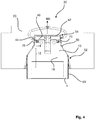
Fig. 4 is a cross-sectional view of a mould according to an embodiment; -
Figs. 5a-d are cross-sectional views of a mould during a closing sequence, showing the outer mould tools moving towards the inner mould tool in order to define the injection moulding cavity; and -
Fig. 6 is a schematic view of a method according to an embodiment. - In
Fig. 1 , a non-limiting example of an injection moulding station 1 is shown which may be incorporated in a filling machine (not shown). The term filling machine is used to characterize a machine which is configured to receive a carton-based packaging material laminate on a roll or in the form of individual blanks, to perform necessary operations to form a sleeve or a packaging container for containing a food product under certain hygienic requirements and to finally seal the packaging container for further distribution. - In the present case, the filling machine is typically configured to produce individual consumer packages enclosing liquid food, while the injection moulding station 1 is configured to a plastic top on a sleeve made from a carton-based packaging material, with a plastic top.
- Two
parallel mandrel wheels 2 are provided in the top right part of the machine 1. Eachmandrel wheel 2 carries fourmandrels 4, spaced apart by 90° in the same plane. Each mandrel has a longitudinal extension in the radial direction of the associatedmandrel wheel 2 and terminates by means of aninner mould tool 10. During operation, themandrel wheels 2 are rotating. At one position, e.g. where themandrels 4 are pointing to the right in the figure (indicated by reference PA), sleeves of a packaging material are fed onto themandrels 4. As themandrel wheels 2 are rotating clock wise, the next position of themandrels 4 is the injection moulding position, further shown inFig. 2 . - In the next consecutive position, cooling of the injection moulded articles can occur, whereby the sleeves (and their associated plastic tops) can be withdrawn from the
mandrels 4. - Now turning to
Fig. 2 , moulds 30 are formed at the injection moulding position. Eachmould 30 comprises aninner mould tool 10, i.e. the longitudinal end portion of themandrel 4, and two moveableouter mould tools 20. - In the injection moulding position, indicated in
Fig. 2 , theouter mould tools 20 are arranged in close proximity to theinner mould tool 10 so that a cavity is formed between them, receiving molten plastic material in accordance with available injection moulding techniques. - In
Fig. 3 themould 30 is shown in a cross-section where oneouter mould tool 20 has been omitted for the purpose of facilitating understanding. Theinner mould tool 10 is arranged at a longitudinal end of themandrel 4, as explained above. Themandrel 4 has a rectangular cross-section, although with rounded corners, in order to define the shape of the carton-based package. Theinner mould tool 10 has aneck part 12, which extends into aspout part 14. The distal end of thespout part 14 is formed by means of abushing 40. Thebushing 40 is provided withside walls 44 which thereby form the longitudinal end of thespout part 14. - The
inner mould tool 10 comprises anouter surface 16 which defines the interior surface of the plastic article to be produced, i.e. the plastic top in the described embodiment. Thebushing 40 has aplanar surface 42 that defines the longitudinal end of theinner mould tool 10, and which extends between theside walls 44. During injection moulding, theplanar surface 42 is in contact with the matingouter mould tools 20. - Now turning to
Fig. 4 themould 30 is shown in a cross-section. Acavity 50 is formed inside themould 30, which cavity is defining the shape of the article to be produced. In this embodiment, the cavity has a ring-shaped cross-section to define the neck and spout of a plastic top. Thecavity 50 has abottom portion 52 which forms an interface to thesleeve 60 of carton-based packaging material, only schematically indicated inFig. 4 . Thecavity 50 extends over theneck part 12 of theinner mould tool 10, as well as over thespout part 14 of theinner mould tool 10. Thecavity 50, whichupper end 54 has a circular or ring-shape, terminates at theplanar surface 42 of thebushing 40 such that theside walls 44 of the bushing also form the boundaries of thecavity 50. Thereby theside walls 44 of thebushing 40 form part of theouter surface 16 of theinner mould tool 10. - The
bushing 40 has a cylindrical shape and extends downwards (in a direction opposite direction of the axis BD inFig. 4 ) in a T-shape. One benefit of the T-shape is improved longitudinal guidance of thebushing 40. We want to point out here, however, that thebushing 40 will also work without the T-shape., As can be seen inFig. 4 , a plurality ofsprings 70 are arranged underneath thebushing 40, supporting thebushing 40 relative amain body 18 of theinner mould tool 10. In this exemplary embodiment six compression springs 70 are distributed at an equal angular distance (60°) from each other. However, as is readily understood a different number of compression springs 70 could be used as well as other types of springs (plate springs, etc.). - The
springs 70 bias thebushing 40 in a longitudinal direction BD, away from themandrel 4, to a longitudinally extended position. This longitudinally extended position, as well as thebushing 40 moving, is shown inFigs. 5a-d . -
Figs. 5a-d show a sequence of theouter mould tools 20 moving from a remote position to an injection moulding position. To fully understand the complex motion of theinner mould tool 10 and theouter mould tools 20, reference is again made toFigs. 1 and2 . Theouter mould tools 20 are moving towards their operational position; during this motion, theinner mould tool 10 is also moving towards the injection moulding position by a rotary motion. This means that theouter mould tools 20 cannot move in a linear manner, but they must be separated from theinner mould tool 10 in the horizontal plane as well as in the longitudinal direction in order to allow theinner mould tool 10 to rotate into its desired position. To achieve this, the motion of theouter mould tools 20 may be controlled by means of abelt drive 80, e.g. as described inWO2004050327 by the same applicant. Thebelt drive 80 is thereby configured to open and close themould 30 by moving theouter mould tools 20 in a first direction which is radial in relation to a hub of themandrel wheels 2 and a second direction which is perpendicular to the first direction and directed in the plane of the circular movement of theinner mould tool 10. Preferably, theouter mould tools 20 are moved so that their central axes coincide throughout the movement. Movement in the first and second directions is preferably performed simultaneously. - In
Fig. 5a the position of theouter mould tools 20 is remote from theinner mould tool 10; the shown position corresponds to when theinner mould tool 10 has reached its injection moulding position, but theouter mould tools 20 still have some distance to travel. - In
Fig. 5b , theouter mould tools 20 have reached theinner mould tool 10 such that theplanar surface 42 of thebushing 40 is in contact with a matingplanar surface 22 of the respectiveouter mould tool 20. As theseplanar surfaces - In
Fig. 5c theouter mould tools 20 have moved further towards each other in the second direction, i.e. in the horizontal direction, such that the vertical end surfaces of theouter mould tools 20 are pressed towards each other (the interface indicated by reference MT inFig. 5c ). During the motion towards its horizontal end position, eachouter mould tool 20 is guided by the sleeve 60 (seeFig. 4 ). This also means that there are no vertical surfaces of the bushing 40 (i.e. the side walls 44) that comes into contact with vertical surfaces of theouter mould tools 20; this is particularly advantageous for the purpose of reducing wear of theouter mould tools 20. During the step inFig. 5c as a polymer material intended to form the top of the packaging container is injected into thecavity 50 between the inner 10 andouter mould tools 20. - In
Fig. 5d the final position of theouter mould tools 20 is shown. Here, theouter mould tools 20 have moved in the vertical direction, thereby pushing thebushing 40 upwards, compressing thesprings 70. In this final step of the moulding process, the polymer melt that has been injected into thecavity 50 between the inner 10 andouter tools 20 is pressed between the tools by the movement of theouter mould tools 20 in relation to theinner tool 10 which is fixed. The maximum longitudinal distance for thebushing 40 to move is in the range of 0,2-0,7 mm, such as 0,5 mm. As can be seen inFig. 5d , the radius of thebushing 40 is less than the radius of themain body 18 of theinner mould 10. Thebushing 40 is thereby slidably guided by themain body 18 during its reciprocal motion. - The
bushing 40 is attached to themain body 18 of theinner mould tool 10 by means of one or more screws 46. The attachment allows for a robust connection, still making it possible for thebushing 40 to move. Thescrews 46 are therefore not connected to the bushing by means of a thread, but only determine the final axial position of the bushing 40 (end stop). - A
lid 48 may be provided to cover thescrews 46. - Now turning to
Fig. 6 amethod 100 for injection moulding a plastic article onto a sleeve of a packaging material is schematically shown. Themethod 100 comprises afirst step 102 of arranging the sleeve of packaging material onto a mandrel, and asecond step 104 of moving two outer mould tools towards an inner mould tool being arranged on said mandrel. In a step 106 a molten polymer material is injected into the cavity formed between the inner mould tool and the outer mould tools when the two outer mould tools have come into contact with each other. Finally, instep 108 the outer mould tools are pressed against the inner mould tool whereby the outer mould tools are guided in a first direction by a planar surface of a bushing provided on the inner mould tool, and in a second direction only by the outer surface of the sleeve. In thisstep 108, the molten polymer material is pressed inside cavity formed between the inner mould tool and the outer mould tools by the movement of the outer tools against the inner tool. - From the description above follows that, although various embodiments of the invention have been described and shown, the invention is not restricted thereto, but may also be embodied in other ways within the scope of the subject-matter defined in the following claims.
Claims (12)
- An inner mould tool (10) forming part of a mould (30) to be used during injection moulding of a plastic article, such as plastic tops for liquid food packages, wherein the inner mould tool (10) comprises an outer surface (16) defining the interior surface of the plastic article to be produced, wherein the longitudinal end of the inner mould tool (10) is provided with a bushing (40) having a planar surface (42) defining the longitudinal end of the inner mould tool (10) and being configured to be in contact with mating outer mould tools (20) during injection moulding, the bushing (40) being provided with side walls (44) extending from the planar surface (42), said side walls (44) forming part of the outer surface (16) of the inner mould tool (10),
characterized in that
the inner mould tool comprises a neck part (12) and a spout part (14), wherein the side walls (44) of the bushing (40) form the longitudinal end of the spout part (14). - The inner mould tool (10) according to claim 1, wherein the bushing (40) is supported by at least one spring (70) biasing the bushing (40) to a longitudinally extended position.
- The inner mould tool (10) according to claim 2, wherein the bushing (40) is projecting longitudinally from a main body (18) of the inner mould tool (10), and wherein the radius of the bushing (40) is less than the radius of the main body (18).
- The inner mould tool (10) according to claim 3, wherein the bushing (40) is attached to the main body (18) of the inner mould tool (10) by means of one or more fastening devices (46).
- The inner mould tool (10) according to claim 1, wherein the bushing (40) has a cylindrical shape.
- A mould (30) to be used during injection moulding of plastic articles, such as plastic tops for liquid food packages, comprising an inner mould tool (10) and at least two outer mould tools (20), said mould tools (20) together defining a cavity (50) to receive molten plastic material during injection moulding, wherein the longitudinal end of the inner mould tool (10) is provided with a bushing (40) having a planar surface (42) defining the longitudinal end of the inner mould tool (10) and being configured to be in contact with mating outer mould tools (20) during injection moulding, characterized in that the bushing (40) is provided with side walls (44) extending from the planar surface (42), said side walls (44) being arranged at a distance from the outer mould tools (20) during injection moulding.
- The mould (30) according to claim 6, wherein the distance between the side walls (44) of the bushing (40) and the outer mould tools (20) forms part of the injection moulding cavity (50).
- The mould (30) according to claim 6 or 7, wherein the inner mould tool (10) is arranged on a mandrel (4) which is configured to receive a sleeve (60) of a packaging material onto which the plastic article is to be injection moulded, wherein the outer mould tools (20) are configured to be in contact with the outer surface of the sleeve (60) during injection moulding.
- The mould (30) according to claim 8, wherein the outer mould tools (20) are guided by the planar surface (42) of the bushing (40) in a first direction, and by the outer surface of the sleeve (60) in a second direction.
- A method for injection moulding a plastic article onto a sleeve of a packaging material, comprising:arranging the sleeve of packaging material onto a mandrel,moving two outer mould tools towards an inner mould tool being arranged on said mandrel until the two outer mould tools contact each other,
injecting molten plastic material into a cavity formed between the inner mould tool and the outer mould tools,pressing said outer mould tools against the inner mould tool thereby pressing the injected molten plastic material inside the cavity formed between the inner mould tool and the outer mould tools, whereby the outer mould tools are guided in a first direction by a planar surface of a bushing provided on the inner mould tool, and in a second direction only by the outer surface of the sleeve, wherein the bushing is provided with side walls extending from the planar surface, said side walls forming part of the outer surface of the inner mould tool. - The method according to claim 10, wherein the first guiding direction is arranged perpendicular to the second guiding direction.
- The method according to claim 10 or 11, wherein pressing said outer mould tools against the inner mould tool is performed such that the bushing is pushed towards the sleeve of packaging material in the longitudinal direction of the sleeve.
Applications Claiming Priority (1)
| Application Number | Priority Date | Filing Date | Title |
|---|---|---|---|
| EP19157507 | 2019-02-15 |
Publications (2)
| Publication Number | Publication Date |
|---|---|
| EP3695948A1 true EP3695948A1 (en) | 2020-08-19 |
| EP3695948B1 EP3695948B1 (en) | 2021-11-24 |
Family
ID=65443774
Family Applications (1)
| Application Number | Title | Priority Date | Filing Date |
|---|---|---|---|
| EP20156014.1A Active EP3695948B1 (en) | 2019-02-15 | 2020-02-07 | A mould, and tools for such mould |
Country Status (5)
| Country | Link |
|---|---|
| US (1) | US12103210B2 (en) |
| EP (1) | EP3695948B1 (en) |
| JP (1) | JP7633935B2 (en) |
| CN (2) | CN213006256U (en) |
| WO (1) | WO2020165028A1 (en) |
Families Citing this family (2)
| Publication number | Priority date | Publication date | Assignee | Title |
|---|---|---|---|---|
| EP3695948B1 (en) * | 2019-02-15 | 2021-11-24 | Tetra Laval Holdings & Finance S.A. | A mould, and tools for such mould |
| CN113768790B (en) * | 2021-09-16 | 2024-03-22 | 安徽大学 | Hydroxypropyl starch hollow capsule preparation device and technology |
Citations (3)
| Publication number | Priority date | Publication date | Assignee | Title |
|---|---|---|---|---|
| JPS57205129A (en) * | 1982-04-19 | 1982-12-16 | Takeuchi Press Kogyo Kk | Extruded tube having check valve |
| US4518554A (en) * | 1982-09-14 | 1985-05-21 | Yoshida Industry Co., Ltd. | Method and apparatus for molding a tubular container with a cap |
| WO2004050327A1 (en) | 2002-11-29 | 2004-06-17 | Tetra Laval Holdings & Finance S.A. | Injection moulding device and a method of opening and closing a partible mould in an injection moulding device |
Family Cites Families (13)
| Publication number | Priority date | Publication date | Assignee | Title |
|---|---|---|---|---|
| US2891283A (en) * | 1956-05-29 | 1959-06-23 | Plastene Corp | Apparatus for molding parts having irregular outer surfaces |
| US3159701A (en) * | 1960-12-12 | 1964-12-01 | George L Herter | Injection molding of plastic ammunition case |
| JPH0211311A (en) * | 1988-06-30 | 1990-01-16 | Fuji Electric Co Ltd | Mold for injection molding |
| JPH02277258A (en) * | 1989-04-18 | 1990-11-13 | Nitto Denko Corp | Semiconductor device |
| JPH04136520A (en) * | 1990-09-27 | 1992-05-11 | Iseki & Co Ltd | Resin bearing |
| JPH05162174A (en) | 1991-12-13 | 1993-06-29 | Yoshida Kogyo Kk <Ykk> | Tube container manufacturing method and tube container |
| JP3313402B2 (en) | 1992-06-11 | 2002-08-12 | 大日本印刷株式会社 | Tube container manufacturing method |
| US5352398A (en) * | 1993-05-06 | 1994-10-04 | Eastman Kodak Company | Apparatus and method for attaching a cap to a mold core |
| US6123231A (en) * | 1998-07-13 | 2000-09-26 | Owens-Brockway Plastic Products Inc. | Plastic container with drain back spout and method and apparatus for making same |
| JP2000113567A (en) * | 1998-10-08 | 2000-04-21 | Mitsubishi Electric Corp | Sound equipment |
| JP4319303B2 (en) * | 1999-10-21 | 2009-08-26 | 大和化成工業株式会社 | Mold structure |
| DK174823B1 (en) * | 2002-04-23 | 2003-12-08 | Hp Ind As | Method of thermoplastic molding of a tubular workpiece |
| EP3695948B1 (en) * | 2019-02-15 | 2021-11-24 | Tetra Laval Holdings & Finance S.A. | A mould, and tools for such mould |
-
2020
- 2020-02-07 EP EP20156014.1A patent/EP3695948B1/en active Active
- 2020-02-07 WO PCT/EP2020/053075 patent/WO2020165028A1/en not_active Ceased
- 2020-02-07 JP JP2021547690A patent/JP7633935B2/en active Active
- 2020-02-07 US US17/422,853 patent/US12103210B2/en active Active
- 2020-02-14 CN CN202020169102.7U patent/CN213006256U/en not_active Withdrawn - After Issue
- 2020-02-14 CN CN202010092220.7A patent/CN111571940B/en active Active
Patent Citations (3)
| Publication number | Priority date | Publication date | Assignee | Title |
|---|---|---|---|---|
| JPS57205129A (en) * | 1982-04-19 | 1982-12-16 | Takeuchi Press Kogyo Kk | Extruded tube having check valve |
| US4518554A (en) * | 1982-09-14 | 1985-05-21 | Yoshida Industry Co., Ltd. | Method and apparatus for molding a tubular container with a cap |
| WO2004050327A1 (en) | 2002-11-29 | 2004-06-17 | Tetra Laval Holdings & Finance S.A. | Injection moulding device and a method of opening and closing a partible mould in an injection moulding device |
Non-Patent Citations (1)
| Title |
|---|
| YURY SHISHKOV: "Tetra Top 3 Filling Machine", 23 June 2017 (2017-06-23), www.youtube.com, XP055608033, Retrieved from the Internet <URL:https://www.youtube.com/watch?v=LNtvz7-aG4g> [retrieved on 20190723] * |
Also Published As
| Publication number | Publication date |
|---|---|
| JP7633935B2 (en) | 2025-02-20 |
| US12103210B2 (en) | 2024-10-01 |
| US20220097268A1 (en) | 2022-03-31 |
| CN111571940A (en) | 2020-08-25 |
| CN111571940B (en) | 2025-09-02 |
| CN213006256U (en) | 2021-04-20 |
| WO2020165028A1 (en) | 2020-08-20 |
| JP2022523173A (en) | 2022-04-21 |
| EP3695948B1 (en) | 2021-11-24 |
Similar Documents
| Publication | Publication Date | Title |
|---|---|---|
| EP3695948B1 (en) | A mould, and tools for such mould | |
| KR101205686B1 (en) | A mold stack for a preform | |
| EP3175969B1 (en) | Blow molding device | |
| CA1036963A (en) | Plastic container closure and manufacture | |
| JP4825271B2 (en) | Package manufacturing method | |
| EP2812172B1 (en) | A method of blowing, filling and capping containers | |
| US9828130B2 (en) | Container handling machine and method | |
| KR20100014326A (en) | Metal mold for compression forming | |
| EP3178630A1 (en) | Blow molding device | |
| CN103465425A (en) | Compression moulding apparatuses and methods | |
| US20110180967A1 (en) | Apparatuses for forming objects with undercut portions | |
| IL222839A (en) | Container with a rim portion defining an opening and method and apparatus for making said container | |
| US20090008810A1 (en) | Compression Moulding Apparatus and Method for Forming Plastics Objects | |
| KR20100061650A (en) | Preform, bottle and preform molding apparatus | |
| RU2164887C1 (en) | Jar for food and method of its making | |
| US20110086749A1 (en) | Manufacturing machine for plastic containers | |
| KR20220014106A (en) | A mold device for form injection molding | |
| US9757899B2 (en) | Device and method for sealing overlapping packaging parts | |
| US20240001427A1 (en) | Method for manufacturing a metal packaging in the form of a bottle | |
| EP3999305B1 (en) | Mold assembly for the production of pet preform and similar plastic products | |
| JP7760822B2 (en) | Mold equipment and injection molding machines | |
| EP4223477A1 (en) | Compression moulding method and device | |
| US20220009147A1 (en) | Apparatus for blow-molding plastic containers | |
| US20060016152A1 (en) | Molding unit for forming direct injection molded closures | |
| JP2007520367A (en) | Molding method and apparatus |
Legal Events
| Date | Code | Title | Description |
|---|---|---|---|
| PUAI | Public reference made under article 153(3) epc to a published international application that has entered the european phase |
Free format text: ORIGINAL CODE: 0009012 |
|
| STAA | Information on the status of an ep patent application or granted ep patent |
Free format text: STATUS: THE APPLICATION HAS BEEN PUBLISHED |
|
| AK | Designated contracting states |
Kind code of ref document: A1 Designated state(s): AL AT BE BG CH CY CZ DE DK EE ES FI FR GB GR HR HU IE IS IT LI LT LU LV MC MK MT NL NO PL PT RO RS SE SI SK SM TR |
|
| AX | Request for extension of the european patent |
Extension state: BA ME |
|
| STAA | Information on the status of an ep patent application or granted ep patent |
Free format text: STATUS: REQUEST FOR EXAMINATION WAS MADE |
|
| 17P | Request for examination filed |
Effective date: 20210219 |
|
| RBV | Designated contracting states (corrected) |
Designated state(s): AL AT BE BG CH CY CZ DE DK EE ES FI FR GB GR HR HU IE IS IT LI LT LU LV MC MK MT NL NO PL PT RO RS SE SI SK SM TR |
|
| GRAP | Despatch of communication of intention to grant a patent |
Free format text: ORIGINAL CODE: EPIDOSNIGR1 |
|
| STAA | Information on the status of an ep patent application or granted ep patent |
Free format text: STATUS: GRANT OF PATENT IS INTENDED |
|
| RIC1 | Information provided on ipc code assigned before grant |
Ipc: B29C 45/14 20060101AFI20210705BHEP Ipc: B29K 711/12 20060101ALN20210705BHEP Ipc: B29L 31/00 20060101ALN20210705BHEP |
|
| INTG | Intention to grant announced |
Effective date: 20210719 |
|
| GRAS | Grant fee paid |
Free format text: ORIGINAL CODE: EPIDOSNIGR3 |
|
| GRAA | (expected) grant |
Free format text: ORIGINAL CODE: 0009210 |
|
| STAA | Information on the status of an ep patent application or granted ep patent |
Free format text: STATUS: THE PATENT HAS BEEN GRANTED |
|
| AK | Designated contracting states |
Kind code of ref document: B1 Designated state(s): AL AT BE BG CH CY CZ DE DK EE ES FI FR GB GR HR HU IE IS IT LI LT LU LV MC MK MT NL NO PL PT RO RS SE SI SK SM TR |
|
| REG | Reference to a national code |
Ref country code: GB Ref legal event code: FG4D |
|
| REG | Reference to a national code |
Ref country code: AT Ref legal event code: REF Ref document number: 1449520 Country of ref document: AT Kind code of ref document: T Effective date: 20211215 |
|
| REG | Reference to a national code |
Ref country code: DE Ref legal event code: R096 Ref document number: 602020001046 Country of ref document: DE |
|
| REG | Reference to a national code |
Ref country code: IE Ref legal event code: FG4D |
|
| REG | Reference to a national code |
Ref country code: LT Ref legal event code: MG9D |
|
| REG | Reference to a national code |
Ref country code: NL Ref legal event code: MP Effective date: 20211124 |
|
| REG | Reference to a national code |
Ref country code: AT Ref legal event code: MK05 Ref document number: 1449520 Country of ref document: AT Kind code of ref document: T Effective date: 20211124 |
|
| PG25 | Lapsed in a contracting state [announced via postgrant information from national office to epo] |
Ref country code: RS Free format text: LAPSE BECAUSE OF FAILURE TO SUBMIT A TRANSLATION OF THE DESCRIPTION OR TO PAY THE FEE WITHIN THE PRESCRIBED TIME-LIMIT Effective date: 20211124 Ref country code: LT Free format text: LAPSE BECAUSE OF FAILURE TO SUBMIT A TRANSLATION OF THE DESCRIPTION OR TO PAY THE FEE WITHIN THE PRESCRIBED TIME-LIMIT Effective date: 20211124 Ref country code: FI Free format text: LAPSE BECAUSE OF FAILURE TO SUBMIT A TRANSLATION OF THE DESCRIPTION OR TO PAY THE FEE WITHIN THE PRESCRIBED TIME-LIMIT Effective date: 20211124 Ref country code: BG Free format text: LAPSE BECAUSE OF FAILURE TO SUBMIT A TRANSLATION OF THE DESCRIPTION OR TO PAY THE FEE WITHIN THE PRESCRIBED TIME-LIMIT Effective date: 20220224 Ref country code: AT Free format text: LAPSE BECAUSE OF FAILURE TO SUBMIT A TRANSLATION OF THE DESCRIPTION OR TO PAY THE FEE WITHIN THE PRESCRIBED TIME-LIMIT Effective date: 20211124 |
|
| PG25 | Lapsed in a contracting state [announced via postgrant information from national office to epo] |
Ref country code: IS Free format text: LAPSE BECAUSE OF FAILURE TO SUBMIT A TRANSLATION OF THE DESCRIPTION OR TO PAY THE FEE WITHIN THE PRESCRIBED TIME-LIMIT Effective date: 20220324 Ref country code: SE Free format text: LAPSE BECAUSE OF FAILURE TO SUBMIT A TRANSLATION OF THE DESCRIPTION OR TO PAY THE FEE WITHIN THE PRESCRIBED TIME-LIMIT Effective date: 20211124 Ref country code: PT Free format text: LAPSE BECAUSE OF FAILURE TO SUBMIT A TRANSLATION OF THE DESCRIPTION OR TO PAY THE FEE WITHIN THE PRESCRIBED TIME-LIMIT Effective date: 20220324 Ref country code: PL Free format text: LAPSE BECAUSE OF FAILURE TO SUBMIT A TRANSLATION OF THE DESCRIPTION OR TO PAY THE FEE WITHIN THE PRESCRIBED TIME-LIMIT Effective date: 20211124 Ref country code: NO Free format text: LAPSE BECAUSE OF FAILURE TO SUBMIT A TRANSLATION OF THE DESCRIPTION OR TO PAY THE FEE WITHIN THE PRESCRIBED TIME-LIMIT Effective date: 20220224 Ref country code: NL Free format text: LAPSE BECAUSE OF FAILURE TO SUBMIT A TRANSLATION OF THE DESCRIPTION OR TO PAY THE FEE WITHIN THE PRESCRIBED TIME-LIMIT Effective date: 20211124 Ref country code: LV Free format text: LAPSE BECAUSE OF FAILURE TO SUBMIT A TRANSLATION OF THE DESCRIPTION OR TO PAY THE FEE WITHIN THE PRESCRIBED TIME-LIMIT Effective date: 20211124 Ref country code: HR Free format text: LAPSE BECAUSE OF FAILURE TO SUBMIT A TRANSLATION OF THE DESCRIPTION OR TO PAY THE FEE WITHIN THE PRESCRIBED TIME-LIMIT Effective date: 20211124 Ref country code: GR Free format text: LAPSE BECAUSE OF FAILURE TO SUBMIT A TRANSLATION OF THE DESCRIPTION OR TO PAY THE FEE WITHIN THE PRESCRIBED TIME-LIMIT Effective date: 20220225 |
|
| PG25 | Lapsed in a contracting state [announced via postgrant information from national office to epo] |
Ref country code: SM Free format text: LAPSE BECAUSE OF FAILURE TO SUBMIT A TRANSLATION OF THE DESCRIPTION OR TO PAY THE FEE WITHIN THE PRESCRIBED TIME-LIMIT Effective date: 20211124 Ref country code: SK Free format text: LAPSE BECAUSE OF FAILURE TO SUBMIT A TRANSLATION OF THE DESCRIPTION OR TO PAY THE FEE WITHIN THE PRESCRIBED TIME-LIMIT Effective date: 20211124 Ref country code: RO Free format text: LAPSE BECAUSE OF FAILURE TO SUBMIT A TRANSLATION OF THE DESCRIPTION OR TO PAY THE FEE WITHIN THE PRESCRIBED TIME-LIMIT Effective date: 20211124 Ref country code: ES Free format text: LAPSE BECAUSE OF FAILURE TO SUBMIT A TRANSLATION OF THE DESCRIPTION OR TO PAY THE FEE WITHIN THE PRESCRIBED TIME-LIMIT Effective date: 20211124 Ref country code: EE Free format text: LAPSE BECAUSE OF FAILURE TO SUBMIT A TRANSLATION OF THE DESCRIPTION OR TO PAY THE FEE WITHIN THE PRESCRIBED TIME-LIMIT Effective date: 20211124 Ref country code: DK Free format text: LAPSE BECAUSE OF FAILURE TO SUBMIT A TRANSLATION OF THE DESCRIPTION OR TO PAY THE FEE WITHIN THE PRESCRIBED TIME-LIMIT Effective date: 20211124 Ref country code: CZ Free format text: LAPSE BECAUSE OF FAILURE TO SUBMIT A TRANSLATION OF THE DESCRIPTION OR TO PAY THE FEE WITHIN THE PRESCRIBED TIME-LIMIT Effective date: 20211124 |
|
| REG | Reference to a national code |
Ref country code: DE Ref legal event code: R097 Ref document number: 602020001046 Country of ref document: DE |
|
| PG25 | Lapsed in a contracting state [announced via postgrant information from national office to epo] |
Ref country code: MC Free format text: LAPSE BECAUSE OF FAILURE TO SUBMIT A TRANSLATION OF THE DESCRIPTION OR TO PAY THE FEE WITHIN THE PRESCRIBED TIME-LIMIT Effective date: 20211124 |
|
| PLBE | No opposition filed within time limit |
Free format text: ORIGINAL CODE: 0009261 |
|
| STAA | Information on the status of an ep patent application or granted ep patent |
Free format text: STATUS: NO OPPOSITION FILED WITHIN TIME LIMIT |
|
| REG | Reference to a national code |
Ref country code: BE Ref legal event code: MM Effective date: 20220228 |
|
| PG25 | Lapsed in a contracting state [announced via postgrant information from national office to epo] |
Ref country code: LU Free format text: LAPSE BECAUSE OF NON-PAYMENT OF DUE FEES Effective date: 20220207 Ref country code: AL Free format text: LAPSE BECAUSE OF FAILURE TO SUBMIT A TRANSLATION OF THE DESCRIPTION OR TO PAY THE FEE WITHIN THE PRESCRIBED TIME-LIMIT Effective date: 20211124 |
|
| 26N | No opposition filed |
Effective date: 20220825 |
|
| PG25 | Lapsed in a contracting state [announced via postgrant information from national office to epo] |
Ref country code: SI Free format text: LAPSE BECAUSE OF FAILURE TO SUBMIT A TRANSLATION OF THE DESCRIPTION OR TO PAY THE FEE WITHIN THE PRESCRIBED TIME-LIMIT Effective date: 20211124 |
|
| PG25 | Lapsed in a contracting state [announced via postgrant information from national office to epo] |
Ref country code: FR Free format text: LAPSE BECAUSE OF NON-PAYMENT OF DUE FEES Effective date: 20220228 |
|
| PG25 | Lapsed in a contracting state [announced via postgrant information from national office to epo] |
Ref country code: IE Free format text: LAPSE BECAUSE OF NON-PAYMENT OF DUE FEES Effective date: 20220207 |
|
| PG25 | Lapsed in a contracting state [announced via postgrant information from national office to epo] |
Ref country code: BE Free format text: LAPSE BECAUSE OF NON-PAYMENT OF DUE FEES Effective date: 20220228 |
|
| P01 | Opt-out of the competence of the unified patent court (upc) registered |
Effective date: 20230426 |
|
| REG | Reference to a national code |
Ref country code: CH Ref legal event code: PL |
|
| PG25 | Lapsed in a contracting state [announced via postgrant information from national office to epo] |
Ref country code: LI Free format text: LAPSE BECAUSE OF NON-PAYMENT OF DUE FEES Effective date: 20230228 Ref country code: CH Free format text: LAPSE BECAUSE OF NON-PAYMENT OF DUE FEES Effective date: 20230228 |
|
| PG25 | Lapsed in a contracting state [announced via postgrant information from national office to epo] |
Ref country code: MK Free format text: LAPSE BECAUSE OF FAILURE TO SUBMIT A TRANSLATION OF THE DESCRIPTION OR TO PAY THE FEE WITHIN THE PRESCRIBED TIME-LIMIT Effective date: 20211124 Ref country code: CY Free format text: LAPSE BECAUSE OF FAILURE TO SUBMIT A TRANSLATION OF THE DESCRIPTION OR TO PAY THE FEE WITHIN THE PRESCRIBED TIME-LIMIT Effective date: 20211124 |
|
| PG25 | Lapsed in a contracting state [announced via postgrant information from national office to epo] |
Ref country code: HU Free format text: LAPSE BECAUSE OF FAILURE TO SUBMIT A TRANSLATION OF THE DESCRIPTION OR TO PAY THE FEE WITHIN THE PRESCRIBED TIME-LIMIT; INVALID AB INITIO Effective date: 20200207 |
|
| PG25 | Lapsed in a contracting state [announced via postgrant information from national office to epo] |
Ref country code: MT Free format text: LAPSE BECAUSE OF FAILURE TO SUBMIT A TRANSLATION OF THE DESCRIPTION OR TO PAY THE FEE WITHIN THE PRESCRIBED TIME-LIMIT Effective date: 20211124 |
|
| GBPC | Gb: european patent ceased through non-payment of renewal fee |
Effective date: 20240207 |
|
| PG25 | Lapsed in a contracting state [announced via postgrant information from national office to epo] |
Ref country code: GB Free format text: LAPSE BECAUSE OF NON-PAYMENT OF DUE FEES Effective date: 20240207 |
|
| PG25 | Lapsed in a contracting state [announced via postgrant information from national office to epo] |
Ref country code: GB Free format text: LAPSE BECAUSE OF NON-PAYMENT OF DUE FEES Effective date: 20240207 |
|
| PG25 | Lapsed in a contracting state [announced via postgrant information from national office to epo] |
Ref country code: TR Free format text: LAPSE BECAUSE OF FAILURE TO SUBMIT A TRANSLATION OF THE DESCRIPTION OR TO PAY THE FEE WITHIN THE PRESCRIBED TIME-LIMIT Effective date: 20211124 |
|
| PGFP | Annual fee paid to national office [announced via postgrant information from national office to epo] |
Ref country code: DE Payment date: 20260220 Year of fee payment: 7 |
|
| PGFP | Annual fee paid to national office [announced via postgrant information from national office to epo] |
Ref country code: IT Payment date: 20260220 Year of fee payment: 7 |