EP3695907A1 - Media type disperser and liquid dispersoid manufacturing method - Google Patents
Media type disperser and liquid dispersoid manufacturing method Download PDFInfo
- Publication number
- EP3695907A1 EP3695907A1 EP18866551.7A EP18866551A EP3695907A1 EP 3695907 A1 EP3695907 A1 EP 3695907A1 EP 18866551 A EP18866551 A EP 18866551A EP 3695907 A1 EP3695907 A1 EP 3695907A1
- Authority
- EP
- European Patent Office
- Prior art keywords
- media
- drive shaft
- stirring blade
- particles
- outlet
- Prior art date
- Legal status (The legal status is an assumption and is not a legal conclusion. Google has not performed a legal analysis and makes no representation as to the accuracy of the status listed.)
- Withdrawn
Links
- 239000007788 liquid Substances 0.000 title claims abstract description 84
- 238000004519 manufacturing process Methods 0.000 title claims description 11
- 239000002245 particle Substances 0.000 claims abstract description 132
- 238000003756 stirring Methods 0.000 claims abstract description 100
- 239000006185 dispersion Substances 0.000 claims abstract description 52
- 239000000203 mixture Substances 0.000 claims abstract description 37
- 238000000926 separation method Methods 0.000 claims description 37
- 239000000463 material Substances 0.000 claims description 34
- 238000000034 method Methods 0.000 claims description 25
- 239000000945 filler Substances 0.000 claims description 13
- 230000002093 peripheral effect Effects 0.000 claims description 12
- 229910052751 metal Inorganic materials 0.000 claims description 8
- 239000002184 metal Substances 0.000 claims description 8
- 239000004699 Ultra-high molecular weight polyethylene Substances 0.000 claims description 7
- 229920000785 ultra high molecular weight polyethylene Polymers 0.000 claims description 7
- 239000002904 solvent Substances 0.000 claims description 5
- 238000005299 abrasion Methods 0.000 abstract description 56
- MCMNRKCIXSYSNV-UHFFFAOYSA-N Zirconium dioxide Chemical compound O=[Zr]=O MCMNRKCIXSYSNV-UHFFFAOYSA-N 0.000 description 24
- 238000011156 evaluation Methods 0.000 description 18
- 230000000052 comparative effect Effects 0.000 description 16
- PNEYBMLMFCGWSK-UHFFFAOYSA-N aluminium oxide Inorganic materials [O-2].[O-2].[O-2].[Al+3].[Al+3] PNEYBMLMFCGWSK-UHFFFAOYSA-N 0.000 description 11
- 239000004698 Polyethylene Substances 0.000 description 10
- 238000005206 flow analysis Methods 0.000 description 10
- 239000000956 alloy Substances 0.000 description 8
- 239000011324 bead Substances 0.000 description 8
- 229910052500 inorganic mineral Inorganic materials 0.000 description 7
- 239000011707 mineral Substances 0.000 description 7
- 230000000694 effects Effects 0.000 description 6
- 229910010293 ceramic material Inorganic materials 0.000 description 5
- 238000010586 diagram Methods 0.000 description 5
- SECXISVLQFMRJM-UHFFFAOYSA-N N-Methylpyrrolidone Chemical compound CN1CCCC1=O SECXISVLQFMRJM-UHFFFAOYSA-N 0.000 description 4
- GWEVSGVZZGPLCZ-UHFFFAOYSA-N Titan oxide Chemical compound O=[Ti]=O GWEVSGVZZGPLCZ-UHFFFAOYSA-N 0.000 description 4
- 229910045601 alloy Inorganic materials 0.000 description 4
- ZWEHNKRNPOVVGH-UHFFFAOYSA-N 2-Butanone Chemical compound CCC(C)=O ZWEHNKRNPOVVGH-UHFFFAOYSA-N 0.000 description 3
- CSCPPACGZOOCGX-UHFFFAOYSA-N Acetone Chemical compound CC(C)=O CSCPPACGZOOCGX-UHFFFAOYSA-N 0.000 description 3
- XEKOWRVHYACXOJ-UHFFFAOYSA-N Ethyl acetate Chemical compound CCOC(C)=O XEKOWRVHYACXOJ-UHFFFAOYSA-N 0.000 description 3
- KFZMGEQAYNKOFK-UHFFFAOYSA-N Isopropanol Chemical compound CC(C)O KFZMGEQAYNKOFK-UHFFFAOYSA-N 0.000 description 3
- OKKJLVBELUTLKV-UHFFFAOYSA-N Methanol Chemical compound OC OKKJLVBELUTLKV-UHFFFAOYSA-N 0.000 description 3
- 229910052581 Si3N4 Inorganic materials 0.000 description 3
- VYPSYNLAJGMNEJ-UHFFFAOYSA-N Silicium dioxide Chemical compound O=[Si]=O VYPSYNLAJGMNEJ-UHFFFAOYSA-N 0.000 description 3
- YXFVVABEGXRONW-UHFFFAOYSA-N Toluene Chemical compound CC1=CC=CC=C1 YXFVVABEGXRONW-UHFFFAOYSA-N 0.000 description 3
- 239000000919 ceramic Substances 0.000 description 3
- 229920001903 high density polyethylene Polymers 0.000 description 3
- 239000004700 high-density polyethylene Substances 0.000 description 3
- 229920001684 low density polyethylene Polymers 0.000 description 3
- 239000004702 low-density polyethylene Substances 0.000 description 3
- 239000000395 magnesium oxide Substances 0.000 description 3
- CPLXHLVBOLITMK-UHFFFAOYSA-N magnesium oxide Inorganic materials [Mg]=O CPLXHLVBOLITMK-UHFFFAOYSA-N 0.000 description 3
- AXZKOIWUVFPNLO-UHFFFAOYSA-N magnesium;oxygen(2-) Chemical compound [O-2].[Mg+2] AXZKOIWUVFPNLO-UHFFFAOYSA-N 0.000 description 3
- VLKZOEOYAKHREP-UHFFFAOYSA-N n-Hexane Chemical compound CCCCCC VLKZOEOYAKHREP-UHFFFAOYSA-N 0.000 description 3
- -1 sialon Chemical compound 0.000 description 3
- HQVNEWCFYHHQES-UHFFFAOYSA-N silicon nitride Chemical compound N12[Si]34N5[Si]62N3[Si]51N64 HQVNEWCFYHHQES-UHFFFAOYSA-N 0.000 description 3
- 239000010935 stainless steel Substances 0.000 description 3
- 229910001220 stainless steel Inorganic materials 0.000 description 3
- MFKRHJVUCZRDTF-UHFFFAOYSA-N 3-methoxy-3-methylbutan-1-ol Chemical compound COC(C)(C)CCO MFKRHJVUCZRDTF-UHFFFAOYSA-N 0.000 description 2
- YEJRWHAVMIAJKC-UHFFFAOYSA-N 4-Butyrolactone Chemical compound O=C1CCCO1 YEJRWHAVMIAJKC-UHFFFAOYSA-N 0.000 description 2
- VTYYLEPIZMXCLO-UHFFFAOYSA-L Calcium carbonate Chemical compound [Ca+2].[O-]C([O-])=O VTYYLEPIZMXCLO-UHFFFAOYSA-L 0.000 description 2
- LFQSCWFLJHTTHZ-UHFFFAOYSA-N Ethanol Chemical compound CCO LFQSCWFLJHTTHZ-UHFFFAOYSA-N 0.000 description 2
- LRHPLDYGYMQRHN-UHFFFAOYSA-N N-Butanol Chemical compound CCCCO LRHPLDYGYMQRHN-UHFFFAOYSA-N 0.000 description 2
- TZCXTZWJZNENPQ-UHFFFAOYSA-L barium sulfate Chemical compound [Ba+2].[O-]S([O-])(=O)=O TZCXTZWJZNENPQ-UHFFFAOYSA-L 0.000 description 2
- 238000001816 cooling Methods 0.000 description 2
- JHIVVAPYMSGYDF-UHFFFAOYSA-N cyclohexanone Chemical compound O=C1CCCCC1 JHIVVAPYMSGYDF-UHFFFAOYSA-N 0.000 description 2
- BGTOWKSIORTVQH-UHFFFAOYSA-N cyclopentanone Chemical compound O=C1CCCC1 BGTOWKSIORTVQH-UHFFFAOYSA-N 0.000 description 2
- 238000005516 engineering process Methods 0.000 description 2
- 235000019441 ethanol Nutrition 0.000 description 2
- LZCLXQDLBQLTDK-UHFFFAOYSA-N ethyl 2-hydroxypropanoate Chemical compound CCOC(=O)C(C)O LZCLXQDLBQLTDK-UHFFFAOYSA-N 0.000 description 2
- 238000010438 heat treatment Methods 0.000 description 2
- PQXKHYXIUOZZFA-UHFFFAOYSA-M lithium fluoride Chemical compound [Li+].[F-] PQXKHYXIUOZZFA-UHFFFAOYSA-M 0.000 description 2
- OGIDPMRJRNCKJF-UHFFFAOYSA-N titanium oxide Inorganic materials [Ti]=O OGIDPMRJRNCKJF-UHFFFAOYSA-N 0.000 description 2
- XLYOFNOQVPJJNP-UHFFFAOYSA-N water Substances O XLYOFNOQVPJJNP-UHFFFAOYSA-N 0.000 description 2
- DAFHKNAQFPVRKR-UHFFFAOYSA-N (3-hydroxy-2,2,4-trimethylpentyl) 2-methylpropanoate Chemical compound CC(C)C(O)C(C)(C)COC(=O)C(C)C DAFHKNAQFPVRKR-UHFFFAOYSA-N 0.000 description 1
- RYHBNJHYFVUHQT-UHFFFAOYSA-N 1,4-Dioxane Chemical compound C1COCCO1 RYHBNJHYFVUHQT-UHFFFAOYSA-N 0.000 description 1
- VXQBJTKSVGFQOL-UHFFFAOYSA-N 2-(2-butoxyethoxy)ethyl acetate Chemical compound CCCCOCCOCCOC(C)=O VXQBJTKSVGFQOL-UHFFFAOYSA-N 0.000 description 1
- KESQFSZFUCZCEI-UHFFFAOYSA-N 2-(5-nitropyridin-2-yl)oxyethanol Chemical compound OCCOC1=CC=C([N+]([O-])=O)C=N1 KESQFSZFUCZCEI-UHFFFAOYSA-N 0.000 description 1
- XNWFRZJHXBZDAG-UHFFFAOYSA-N 2-METHOXYETHANOL Chemical compound COCCO XNWFRZJHXBZDAG-UHFFFAOYSA-N 0.000 description 1
- POAOYUHQDCAZBD-UHFFFAOYSA-N 2-butoxyethanol Chemical compound CCCCOCCO POAOYUHQDCAZBD-UHFFFAOYSA-N 0.000 description 1
- NQBXSWAWVZHKBZ-UHFFFAOYSA-N 2-butoxyethyl acetate Chemical compound CCCCOCCOC(C)=O NQBXSWAWVZHKBZ-UHFFFAOYSA-N 0.000 description 1
- ZNQVEEAIQZEUHB-UHFFFAOYSA-N 2-ethoxyethanol Chemical compound CCOCCO ZNQVEEAIQZEUHB-UHFFFAOYSA-N 0.000 description 1
- 239000005995 Aluminium silicate Substances 0.000 description 1
- 229910000975 Carbon steel Inorganic materials 0.000 description 1
- XDTMQSROBMDMFD-UHFFFAOYSA-N Cyclohexane Chemical compound C1CCCCC1 XDTMQSROBMDMFD-UHFFFAOYSA-N 0.000 description 1
- XBDQKXXYIPTUBI-UHFFFAOYSA-M Propionate Chemical compound CCC([O-])=O XBDQKXXYIPTUBI-UHFFFAOYSA-M 0.000 description 1
- 229920010741 Ultra High Molecular Weight Polyethylene (UHMWPE) Polymers 0.000 description 1
- 229910009043 WC-Co Inorganic materials 0.000 description 1
- KXKVLQRXCPHEJC-UHFFFAOYSA-N acetic acid trimethyl ester Natural products COC(C)=O KXKVLQRXCPHEJC-UHFFFAOYSA-N 0.000 description 1
- 150000001298 alcohols Chemical class 0.000 description 1
- WUOACPNHFRMFPN-UHFFFAOYSA-N alpha-terpineol Chemical compound CC1=CCC(C(C)(C)O)CC1 WUOACPNHFRMFPN-UHFFFAOYSA-N 0.000 description 1
- 235000012211 aluminium silicate Nutrition 0.000 description 1
- 229910001593 boehmite Inorganic materials 0.000 description 1
- 229910000019 calcium carbonate Inorganic materials 0.000 description 1
- WUKWITHWXAAZEY-UHFFFAOYSA-L calcium difluoride Chemical compound [F-].[F-].[Ca+2] WUKWITHWXAAZEY-UHFFFAOYSA-L 0.000 description 1
- 229910001634 calcium fluoride Inorganic materials 0.000 description 1
- 239000001506 calcium phosphate Substances 0.000 description 1
- 229910000389 calcium phosphate Inorganic materials 0.000 description 1
- 235000011010 calcium phosphates Nutrition 0.000 description 1
- 239000010962 carbon steel Substances 0.000 description 1
- 239000002131 composite material Substances 0.000 description 1
- 239000002826 coolant Substances 0.000 description 1
- PMHQVHHXPFUNSP-UHFFFAOYSA-M copper(1+);methylsulfanylmethane;bromide Chemical compound Br[Cu].CSC PMHQVHHXPFUNSP-UHFFFAOYSA-M 0.000 description 1
- SQIFACVGCPWBQZ-UHFFFAOYSA-N delta-terpineol Natural products CC(C)(O)C1CCC(=C)CC1 SQIFACVGCPWBQZ-UHFFFAOYSA-N 0.000 description 1
- HNPSIPDUKPIQMN-UHFFFAOYSA-N dioxosilane;oxo(oxoalumanyloxy)alumane Chemical compound O=[Si]=O.O=[Al]O[Al]=O HNPSIPDUKPIQMN-UHFFFAOYSA-N 0.000 description 1
- 150000002148 esters Chemical class 0.000 description 1
- 229940116333 ethyl lactate Drugs 0.000 description 1
- 239000011521 glass Substances 0.000 description 1
- 229930195733 hydrocarbon Natural products 0.000 description 1
- 150000002430 hydrocarbons Chemical class 0.000 description 1
- FAHBNUUHRFUEAI-UHFFFAOYSA-M hydroxidooxidoaluminium Chemical compound O[Al]=O FAHBNUUHRFUEAI-UHFFFAOYSA-M 0.000 description 1
- GJRQTCIYDGXPES-UHFFFAOYSA-N iso-butyl acetate Natural products CC(C)COC(C)=O GJRQTCIYDGXPES-UHFFFAOYSA-N 0.000 description 1
- FGKJLKRYENPLQH-UHFFFAOYSA-M isocaproate Chemical compound CC(C)CCC([O-])=O FGKJLKRYENPLQH-UHFFFAOYSA-M 0.000 description 1
- JMMWKPVZQRWMSS-UHFFFAOYSA-N isopropanol acetate Natural products CC(C)OC(C)=O JMMWKPVZQRWMSS-UHFFFAOYSA-N 0.000 description 1
- 229940011051 isopropyl acetate Drugs 0.000 description 1
- GWYFCOCPABKNJV-UHFFFAOYSA-N isovaleric acid Chemical compound CC(C)CC(O)=O GWYFCOCPABKNJV-UHFFFAOYSA-N 0.000 description 1
- OQAGVSWESNCJJT-UHFFFAOYSA-N isovaleric acid methyl ester Natural products COC(=O)CC(C)C OQAGVSWESNCJJT-UHFFFAOYSA-N 0.000 description 1
- NLYAJNPCOHFWQQ-UHFFFAOYSA-N kaolin Chemical compound O.O.O=[Al]O[Si](=O)O[Si](=O)O[Al]=O NLYAJNPCOHFWQQ-UHFFFAOYSA-N 0.000 description 1
- 150000002576 ketones Chemical class 0.000 description 1
- 239000007769 metal material Substances 0.000 description 1
- 150000002739 metals Chemical class 0.000 description 1
- XVTQAXXMUNXFMU-UHFFFAOYSA-N methyl 2-(3-oxo-2-pyridin-2-yl-1h-pyrazol-5-yl)acetate Chemical compound N1C(CC(=O)OC)=CC(=O)N1C1=CC=CC=N1 XVTQAXXMUNXFMU-UHFFFAOYSA-N 0.000 description 1
- 239000010445 mica Substances 0.000 description 1
- 229910052618 mica group Inorganic materials 0.000 description 1
- 238000002156 mixing Methods 0.000 description 1
- 230000004048 modification Effects 0.000 description 1
- 238000012986 modification Methods 0.000 description 1
- CWQXQMHSOZUFJS-UHFFFAOYSA-N molybdenum disulfide Chemical compound S=[Mo]=S CWQXQMHSOZUFJS-UHFFFAOYSA-N 0.000 description 1
- WVDDGKGOMKODPV-ZQBYOMGUSA-N phenyl(114C)methanol Chemical compound O[14CH2]C1=CC=CC=C1 WVDDGKGOMKODPV-ZQBYOMGUSA-N 0.000 description 1
- 229920005569 poly(vinylidene fluoride-co-hexafluoropropylene) Polymers 0.000 description 1
- 229920000573 polyethylene Polymers 0.000 description 1
- 229920001343 polytetrafluoroethylene Polymers 0.000 description 1
- 239000004810 polytetrafluoroethylene Substances 0.000 description 1
- 229920002981 polyvinylidene fluoride Polymers 0.000 description 1
- 239000000843 powder Substances 0.000 description 1
- 239000011164 primary particle Substances 0.000 description 1
- BDERNNFJNOPAEC-UHFFFAOYSA-N propan-1-ol Chemical compound CCCO BDERNNFJNOPAEC-UHFFFAOYSA-N 0.000 description 1
- 229940090181 propyl acetate Drugs 0.000 description 1
- LLHKCFNBLRBOGN-UHFFFAOYSA-N propylene glycol methyl ether acetate Chemical compound COCC(C)OC(C)=O LLHKCFNBLRBOGN-UHFFFAOYSA-N 0.000 description 1
- 238000010298 pulverizing process Methods 0.000 description 1
- 230000009257 reactivity Effects 0.000 description 1
- 239000011347 resin Substances 0.000 description 1
- 229920005989 resin Polymers 0.000 description 1
- HBMJWWWQQXIZIP-UHFFFAOYSA-N silicon carbide Chemical compound [Si+]#[C-] HBMJWWWQQXIZIP-UHFFFAOYSA-N 0.000 description 1
- 229910010271 silicon carbide Inorganic materials 0.000 description 1
- 239000002002 slurry Substances 0.000 description 1
- 239000000454 talc Substances 0.000 description 1
- 229910052623 talc Inorganic materials 0.000 description 1
- 229940116411 terpineol Drugs 0.000 description 1
- QORWJWZARLRLPR-UHFFFAOYSA-H tricalcium bis(phosphate) Chemical compound [Ca+2].[Ca+2].[Ca+2].[O-]P([O-])([O-])=O.[O-]P([O-])([O-])=O QORWJWZARLRLPR-UHFFFAOYSA-H 0.000 description 1
- 238000011144 upstream manufacturing Methods 0.000 description 1
- 238000011179 visual inspection Methods 0.000 description 1
- 239000008096 xylene Substances 0.000 description 1
- 150000003738 xylenes Chemical class 0.000 description 1
Images

Classifications
-
- B—PERFORMING OPERATIONS; TRANSPORTING
- B02—CRUSHING, PULVERISING, OR DISINTEGRATING; PREPARATORY TREATMENT OF GRAIN FOR MILLING
- B02C—CRUSHING, PULVERISING, OR DISINTEGRATING IN GENERAL; MILLING GRAIN
- B02C17/00—Disintegrating by tumbling mills, i.e. mills having a container charged with the material to be disintegrated with or without special disintegrating members such as pebbles or balls
- B02C17/16—Mills in which a fixed container houses stirring means tumbling the charge
- B02C17/163—Stirring means
-
- B—PERFORMING OPERATIONS; TRANSPORTING
- B01—PHYSICAL OR CHEMICAL PROCESSES OR APPARATUS IN GENERAL
- B01F—MIXING, e.g. DISSOLVING, EMULSIFYING OR DISPERSING
- B01F27/00—Mixers with rotary stirring devices in fixed receptacles; Kneaders
- B01F27/60—Mixers with rotary stirring devices in fixed receptacles; Kneaders with stirrers rotating about a horizontal or inclined axis
- B01F27/70—Mixers with rotary stirring devices in fixed receptacles; Kneaders with stirrers rotating about a horizontal or inclined axis with paddles, blades or arms
-
- B—PERFORMING OPERATIONS; TRANSPORTING
- B01—PHYSICAL OR CHEMICAL PROCESSES OR APPARATUS IN GENERAL
- B01F—MIXING, e.g. DISSOLVING, EMULSIFYING OR DISPERSING
- B01F23/00—Mixing according to the phases to be mixed, e.g. dispersing or emulsifying
- B01F23/50—Mixing liquids with solids
- B01F23/57—Mixing high-viscosity liquids with solids
-
- B—PERFORMING OPERATIONS; TRANSPORTING
- B01—PHYSICAL OR CHEMICAL PROCESSES OR APPARATUS IN GENERAL
- B01F—MIXING, e.g. DISSOLVING, EMULSIFYING OR DISPERSING
- B01F27/00—Mixers with rotary stirring devices in fixed receptacles; Kneaders
- B01F27/05—Stirrers
- B01F27/11—Stirrers characterised by the configuration of the stirrers
- B01F27/115—Stirrers characterised by the configuration of the stirrers comprising discs or disc-like elements essentially perpendicular to the stirrer shaft axis
- B01F27/1152—Stirrers characterised by the configuration of the stirrers comprising discs or disc-like elements essentially perpendicular to the stirrer shaft axis with separate elements other than discs fixed on the discs, e.g. vanes fixed on the discs
-
- B—PERFORMING OPERATIONS; TRANSPORTING
- B01—PHYSICAL OR CHEMICAL PROCESSES OR APPARATUS IN GENERAL
- B01F—MIXING, e.g. DISSOLVING, EMULSIFYING OR DISPERSING
- B01F27/00—Mixers with rotary stirring devices in fixed receptacles; Kneaders
- B01F27/05—Stirrers
- B01F27/11—Stirrers characterised by the configuration of the stirrers
- B01F27/19—Stirrers with two or more mixing elements mounted in sequence on the same axis
-
- B—PERFORMING OPERATIONS; TRANSPORTING
- B01—PHYSICAL OR CHEMICAL PROCESSES OR APPARATUS IN GENERAL
- B01F—MIXING, e.g. DISSOLVING, EMULSIFYING OR DISPERSING
- B01F27/00—Mixers with rotary stirring devices in fixed receptacles; Kneaders
- B01F27/60—Mixers with rotary stirring devices in fixed receptacles; Kneaders with stirrers rotating about a horizontal or inclined axis
- B01F27/73—Mixers with rotary stirring devices in fixed receptacles; Kneaders with stirrers rotating about a horizontal or inclined axis with rotary discs
-
- B—PERFORMING OPERATIONS; TRANSPORTING
- B01—PHYSICAL OR CHEMICAL PROCESSES OR APPARATUS IN GENERAL
- B01F—MIXING, e.g. DISSOLVING, EMULSIFYING OR DISPERSING
- B01F35/00—Accessories for mixers; Auxiliary operations or auxiliary devices; Parts or details of general application
- B01F35/181—Preventing generation of dust or dirt; Sieves; Filters
- B01F35/187—Preventing generation of dust or dirt; Sieves; Filters using filters in mixers, e.g. during venting
-
- B—PERFORMING OPERATIONS; TRANSPORTING
- B01—PHYSICAL OR CHEMICAL PROCESSES OR APPARATUS IN GENERAL
- B01F—MIXING, e.g. DISSOLVING, EMULSIFYING OR DISPERSING
- B01F35/00—Accessories for mixers; Auxiliary operations or auxiliary devices; Parts or details of general application
- B01F35/71—Feed mechanisms
-
- B—PERFORMING OPERATIONS; TRANSPORTING
- B02—CRUSHING, PULVERISING, OR DISINTEGRATING; PREPARATORY TREATMENT OF GRAIN FOR MILLING
- B02C—CRUSHING, PULVERISING, OR DISINTEGRATING IN GENERAL; MILLING GRAIN
- B02C17/00—Disintegrating by tumbling mills, i.e. mills having a container charged with the material to be disintegrated with or without special disintegrating members such as pebbles or balls
- B02C17/16—Mills in which a fixed container houses stirring means tumbling the charge
- B02C17/161—Arrangements for separating milling media and ground material
-
- B—PERFORMING OPERATIONS; TRANSPORTING
- B02—CRUSHING, PULVERISING, OR DISINTEGRATING; PREPARATORY TREATMENT OF GRAIN FOR MILLING
- B02C—CRUSHING, PULVERISING, OR DISINTEGRATING IN GENERAL; MILLING GRAIN
- B02C17/00—Disintegrating by tumbling mills, i.e. mills having a container charged with the material to be disintegrated with or without special disintegrating members such as pebbles or balls
- B02C17/18—Details
- B02C17/183—Feeding or discharging devices
-
- B—PERFORMING OPERATIONS; TRANSPORTING
- B02—CRUSHING, PULVERISING, OR DISINTEGRATING; PREPARATORY TREATMENT OF GRAIN FOR MILLING
- B02C—CRUSHING, PULVERISING, OR DISINTEGRATING IN GENERAL; MILLING GRAIN
- B02C17/00—Disintegrating by tumbling mills, i.e. mills having a container charged with the material to be disintegrated with or without special disintegrating members such as pebbles or balls
- B02C17/18—Details
- B02C17/24—Driving mechanisms
-
- B—PERFORMING OPERATIONS; TRANSPORTING
- B01—PHYSICAL OR CHEMICAL PROCESSES OR APPARATUS IN GENERAL
- B01F—MIXING, e.g. DISSOLVING, EMULSIFYING OR DISPERSING
- B01F2101/00—Mixing characterised by the nature of the mixed materials or by the application field
- B01F2101/2805—Mixing plastics, polymer material ingredients, monomers or oligomers
-
- B—PERFORMING OPERATIONS; TRANSPORTING
- B01—PHYSICAL OR CHEMICAL PROCESSES OR APPARATUS IN GENERAL
- B01F—MIXING, e.g. DISSOLVING, EMULSIFYING OR DISPERSING
- B01F2215/00—Auxiliary or complementary information in relation with mixing
- B01F2215/04—Technical information in relation with mixing
- B01F2215/0413—Numerical information
- B01F2215/0418—Geometrical information
- B01F2215/0431—Numerical size values, e.g. diameter of a hole or conduit, area, volume, length, width, or ratios thereof
-
- B—PERFORMING OPERATIONS; TRANSPORTING
- B01—PHYSICAL OR CHEMICAL PROCESSES OR APPARATUS IN GENERAL
- B01F—MIXING, e.g. DISSOLVING, EMULSIFYING OR DISPERSING
- B01F2215/00—Auxiliary or complementary information in relation with mixing
- B01F2215/04—Technical information in relation with mixing
- B01F2215/0413—Numerical information
- B01F2215/0436—Operational information
- B01F2215/0481—Numerical speed values
-
- B—PERFORMING OPERATIONS; TRANSPORTING
- B01—PHYSICAL OR CHEMICAL PROCESSES OR APPARATUS IN GENERAL
- B01F—MIXING, e.g. DISSOLVING, EMULSIFYING OR DISPERSING
- B01F2215/00—Auxiliary or complementary information in relation with mixing
- B01F2215/04—Technical information in relation with mixing
- B01F2215/0413—Numerical information
- B01F2215/0486—Material property information
- B01F2215/0495—Numerical values of viscosity of substances
Definitions
- the present invention relates to a media-type disperser and a method for producing a liquid dispersion.
- a typical media-type disperser is one in which stirring blades (stirring discs) and media particles are housed in a cylindrical vessel; however, the abrasion of the stirring blade and the inner wall of the vessel has been a problem.
- a means for dividing of a liquid dispersion and media particles such as a screen or a gap separator, is provided in a cylindrical vessel of a media-type disperser; however, there has been a problem of the clogging of the screen etc. due to media particles.
- an object of the present invention is to provide a media-type disperser and a method for producing a liquid dispersion that can improve productivity while suppressing damage due to abrasion of a screen or a gap separator.
- the present invention mainly include any of the following configurations.
- productivity can be improved while damage due to abrasion of a screen or of a gap separator in a media-type disperser is suppressed.
- a drive shaft, a plurality of stirring blades (stirring discs) that are arranged on the drive shaft and are simultaneously rotatable by the rotation of the drive shaft, and media particles are housed in a cylindrical vessel having a supply port of a liquid mixture and an outlet of a liquid dispersion.
- the liquid mixture refers to a source material mixture that is passed through the media-type disperser
- the liquid dispersion refers to a dispersion of the source material mixture that has been passed through the media-type disperser, excluding the media.
- the stirring blade nearest to the outlet has a protrusion in a direction parallel to the drive shaft; and the thickness t (mm) of the protrusion, the diameter d (mm) of the media particle, and the distance L (mm) from the outlet side of the stirring blade nearest to the outlet to the rear end of the cylindrical vessel satisfy Formula (1) below. 10 d ⁇ t ⁇ L ⁇ 10 d
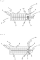
- Fig. 1 shows a schematic diagram showing an embodiment of the media-type disperser of the present invention.
- the media-type disperser includes a drive shaft 2 in a cylindrical vessel 1, and includes, on the drive shaft 2, a plurality of stirring blades 3 that are simultaneously rotatable by the rotation of the drive shaft 2.
- the center axis of the cylindrical vessel 1 and the drive shaft 2 are preferably coaxial.
- Each of the plurality of stirring blades 3 may basically be a platelike body of a circle or the like that is rotated by the rotation of the drive shaft 2; among these, a stirring blade 3' nearest to an outlet 6 has a protrusion 10 protruding in a direction parallel to the drive shaft 2.
- the protrusion is preferably provided on the outlet side of the stirring blade nearest to the outlet.
- a rotor 7 rotatable by the rotation of the drive shaft 2 and a stator 8, which is a fixed ring, are provided still more on the outlet 6 side than the stirring blade 3' nearest to the outlet 6 in the cylindrical vessel 1.
- the stator 8 is integrated with a head cover 9 that is provided in a liquid-tight manner to an end portion on the outlet 6 side of the cylindrical vessel 1. Further, not-illustrated media particles are provided in the cylindrical vessel 1.
- a liquid mixture is caused to flow from a supply port 4 into a dispersing chamber 5 in which media particles are put, is finely dispersed by the collision etc. of media particles accelerated by the stirring blades 3 that are rotating and becomes a liquid dispersion, and is discharged from the outlet 6 to the outside of the cylindrical vessel 1.
- the arrow indicates the flowing direction of the liquid mixture and the liquid dispersion.
- the stirring blade nearest to the outlet of a liquid dispersion has a protrusion; thereby, the speed of media particles in a direction parallel to the rotation direction of the drive shaft is increased, and the difference between the peripheral speed of the rotor being rotated by the rotation of the drive shaft and the speed in a direction parallel to the rotation direction of the media particle in the vicinity of the rotor can be reduced; thus, damage due to abrasion of the screen or the gap separator can be suppressed.
- the average relative speed Vn between the speed in the rotation direction of the media particle existing in a position up to 1 mm from the stator toward the rotor in a direction parallel to the drive shaft and the speed of the rotor being rotated by the rotation of the drive shaft can be caused to satisfy the relation of Formula (2) below.
- the speed of the media particle encompasses the speeds of all the media particles existing in the position described above and the speed of the rotor refers to the speed on the outer peripheral surface of the rotor, and the average value of the relative speeds between them is taken as the average relative speed Vn.
- the speeds of the media particles existing in the position described above are not greatly different between the inner side and the outer side with respect to the diameter direction of the drive shaft and representation by media particles in a partial region alone is allowable, such representation may be employed.
- Fig. 2 shows an enlarged view of the stirring blade nearest to the outlet and of the neighborhood of the gap separator in an embodiment of the media-type disperser of the present invention.
- the thickness t (mm) of the protrusion possessed by the stirring blade nearest to the outlet, the diameter d (mm) of the media particle, and the distance L (mm) from the outlet side of the stirring blade nearest to the outlet to the rear end of the cylindrical vessel satisfy Formula (1) below.
- the thickness t of the protrusion is the length in a direction parallel to the drive shaft, and refers to the thickness of the thickest portion in a direction parallel to the drive shaft.
- the diameter d of the media particle refers to the number average value of the long diameters of 200 randomly selected media particles.
- the distance L from the outlet side of the stirring blade nearest to the outlet to the rear end of the cylindrical vessel refers to the distance from the outlet side of the portion excluding the protrusion 10 of the stirring blade 3' nearest to the outlet to the head cover 9. 10 d ⁇ t ⁇ L ⁇ 10 d
- the thickness t of the protrusion is smaller than 10d, the effect of the protrusion is not sufficiently obtained, and hence damage due to abrasion of the screen or the gap separator is likely to occur.
- the thickness t of the protrusion is larger than L - 10d, media particles are likely to be caught in the gap between the protrusion of the stirring blade and the gap separator, and the fluidity of media particles is reduced and the internal pressure rises; consequently, productivity is reduced.
- the thickness t of the protrusion is preferably more than or equal to L/2.
- the speed in a direction parallel to the rotation direction of the media particle is made larger, and damage due to abrasion of the screen or the gap separator can be suppressed more.
- the distance L from the outlet side of the stirring blade nearest to the outlet to the rear end of the cylindrical vessel is preferably more than or equal to the length of a separation mechanism in a direction parallel to the drive shaft and less than or equal to 1.2 times the length of the separation mechanism, in order to sufficiently obtain the effect of the protrusion.
- the length of the separation mechanism is the length in the direction of the drive shaft of a rotor in the case of the separation mechanism adopting a gap separator system like that shown in Figs. 1 and 2 , and is the length in the direction of the drive shaft of a screen in the case of the separation mechanism adopting a screen system.
- the thickness t (mm) of the protrusion and the distance L (mm) from the outlet side of the portion excluding the protrusion of the stirring blade nearest to the outlet to the rear end of the cylindrical vessel can be measured using vernier calipers.
- the diameter d (mm) of the media particle can be found by observing media particles with a microscope with a magnification of 100 times, measuring the long diameters of 200 randomly selected media particles, and calculating the number average value of them.
- the protrusion may have any length in the diameter direction of the drive shaft, but it is preferable that the end on the outer peripheral side of the protrusion be provided more on the outer side than the middle position between the center and the outermost periphery of the stirring blade nearest to the outlet.
- the end on the outer peripheral side of the protrusion is located more on the outer side than the middle position between the center and the outermost periphery of the stirring blade, the angular velocity of the protrusion is large, and the speed of media particles in a direction parallel to the rotation direction of the protrusion is large; thus, the effect of the protrusion can be sufficiently obtained.
- a plurality of protrusions be provided.
- the outer peripheral side of the protrusion has a larger area on the same circumference, the effect of the protrusion can be obtained more, but the passage of the liquid dispersion is reduced and a rise in the internal pressure is caused; thus, the protrusion may be divided into a plurality of pieces, and thereby a rise in the internal pressure can be suppressed.
- the protrusion more preferably has a tapered shape from the inner side to the outer side in the diameter direction of the stirring blade.
- the media-type disperser preferably has, in the cylindrical vessel, a separation mechanism that separates the media particles and the liquid dispersion.
- the separation mechanism include a gap separator, a screen, a slit, a mesh, and the like.
- a gap separator system is preferable.
- the gap separator system is a system that includes a rotor rotatable by the rotation of the drive shaft and a stator, which is a fixed ring, and that separates the liquid dispersion and the media particles by only the liquid dispersion passing through the gap between the rotor and the stator.
- the separation mechanism adopting a gap separator system can shorten the distance between the stirring blade nearest to the outlet and the separation mechanism; thus, the dispersing region in the cylindrical vessel can be utilized as much as possible, and productivity can be improved more.
- examples of the material of the stirring blade include super hard alloy materials, ceramic materials, metals, materials each with a Young's modulus of 0.4 to 0.6 GPa, and the like.
- examples of the super hard alloy material include WC-Co-based alloys, WC-TiC-Co-based alloys, WC-TaC-Co-based alloys, WC-TiC-TaC-Co-based alloys, and the like.
- examples of the ceramic material include zirconia, alumina, silicon carbide, aluminum nitride, sialon, zirconia toughened alumina, and the like. Zirconia and zirconia toughened alumina are preferable from the viewpoints of abrasion resistance, the thermal conductivity, and the coefficient of thermal expansion.
- examples of the metal include stainless steel, carbon steel, and the like.
- the stirring blade be made of a material with a Young's modulus of 0.4 to 0.6 GPa, and it is more preferable that a portion that media particles and a liquid mixture are in contact with be made of a material with a Young's modulus of 0.4 to 0.6 GPa.
- the Young's modulus can be measured by a method prescribed by JIS K7161-1:2014 in the case of resin materials and by a method prescribed by JIS R1602:1995 in the case of ceramic and metal-based materials.
- Examples of the material with a Young's modulus of 0.4 to 0.6 GPa include ultrahigh molecular weight polyethylene, polytetrafluoroethylene, and the like. Among these, ultrahigh molecular weight polyethylene is more preferable because it is light in weight and excellent in maintainability.
- the ultrahigh molecular weight polyethylene refers generally to polyethylene with a weight-average molecular weight of more than or equal to one million. The molecular weight of the ultrahigh molecular weight polyethylene is preferably less than or equal to seven million.
- the material of a portion of the stirring blade that media particles and a liquid mixture are not in contact with is preferably a metal and more preferably stainless steel from the viewpoint of mechanical strength.
- the material of the drive shaft for rotating the stirring blade is preferably a metal from the viewpoint of mechanical strength. Those given as examples of the material of the stirring blade are given as the metal.
- the surface of the drive shaft is preferably covered with a ceramic or ultrahigh molecular weight polyethylene from the viewpoint of suppressing the mixing of metal powder due to abrasion into a liquid dispersion.
- a cover of a ceramic or ultrahigh molecular weight polyethylene may be provided on a metal drive shaft.
- Examples of the material of the inner wall of the cylindrical vessel include super hard alloy materials, ceramic materials, stainless steel, materials each with a Young's modulus of 0.4 to 0.6 GPa, and the like. It is preferable that a ceramic material be selected when high thermal conductivity is required and a material with a Young's modulus of 0.4 to 0.6 GPa be selected when higher abrasion resistance is required. Those given as examples of the respective types of material of the stirring blade and the like are given as the super hard alloy material, the ceramic material, and the material with a Young's modulus of 0.4 to 0.6 GPa.
- the inner wall of the cylindrical vessel have a structure capable of introducing a cooling or heating medium and that dispersion be performed while the temperature of the liquid dispersion is controlled by the cooling or heating medium.
- a cooling medium may be used to keep the temperature of the liquid dispersion less than or equal to a certain temperature, and thereby the quality reduction of the liquid dispersion can be suppressed.
- the media particle receives strong collision energy by the rotation of the stirring blade; thus, particles of zirconia, alumina, or the like are suitably used from the viewpoint of abrasion resistance.
- the gap between the rotor and the stator is generally more than or equal to 0.1 mm; thus, the diameter d of the media particle is preferably more than or equal to 0.3 mm from the viewpoint of the protection of the equipment.
- the media-type disperser of the present invention preferably has a metering pump upstream of the supply port of a liquid mixture, and can perform continuous dispersion treatment by continuously supplying a liquid mixture. Further, the dispersibility of a liquid dispersion can be stabilized by quantitatively supplying a liquid mixture.
- the metering pump examples include centrifugal pumps such as a single-stage turbine pump and a bore hole, propeller pumps such as an axial flow pump and a mixed flow pump, viscous pumps such as a single-stage centrifugal pump and a multi-stage centrifugal pump, reciprocating pumps such as a lateral piston pump, a vertical piston pump, a horizontal piston pump, a horizontal plunger pump, a vertical plunger pump, a diaphragm pump, a tube pump, and a wing pump, rotary pumps such as an external gear pump, an internal gear pump, an eccentric screw pump, a vane pump, and a roller pump, and the like.
- centrifugal pumps such as a single-stage turbine pump and a bore hole
- propeller pumps such as an axial flow pump and a mixed flow pump
- viscous pumps such as a single-stage centrifugal pump and a multi-stage centrifugal pump
- reciprocating pumps such as a lateral piston pump, a vertical piston pump
- the method preferably has a step of dispersing a liquid mixture containing at least filler particles and a solvent by using the media-type disperser described above.
- filler particles examples include calcium carbonate particles, calcium phosphate particles, amorphous silica particles, crystalline glass filler, kaolin particles, talc particles, titania particles, alumina particles, silica-alumina composite oxide particles, barium sulphate particles, calcium fluoride particles, lithium fluoride particles, zeolite particles, molybdenum sulfide particles, mica particles, boehmite particles, zirconia particles, magnesium oxide particles, titanium oxide particles, silicon nitride, and the like. It is preferable that, in the liquid dispersion, the filler particles contained in the liquid dispersion be sufficiently dispersed up to the primary particle sizes while maintaining required particle sizes and surface characteristics.
- the Mohs hardness of the filler particle is preferably more than or equal to 4 in order to suppress surface modification due to pulverization of the filler particle by a media particle.
- Examples of the filler particle with a Mohs hardness of more than or equal to 4 include alumina particles, amorphous silica particles, magnesium oxide particles, titanium oxide particles, silicon nitride particles, zirconia particles, and the like.
- the Mohs hardness shows the hardness to minerals, and can be measured using a commercially available 10-grade Mohs hardness meter. Specifically, a material of interest and each of the minerals used as the ranks in the 10-grade Mohs hardness meter are rubbed together, and then the presence or absence of a flaw is visually observed. In the case where both of the material and the mineral of a specific grade are flawed or neither of them is flawed, the same grade as the grade of the mineral of the specific grade used is taken as the Mohs hardness of the material.
- the filler particles are preferably electrical insulating particles.
- the electrical insulating properties mean that the volume resistivity of the material is more than or equal to 10 14 ⁇ cm.
- the volume resistivity of the material can be measured by a method prescribed by JIS C2141:1992.
- Examples of electrical insulating particles include alumina particles, amorphous silica particles, magnesium oxide particles, silicon nitride particles, zirconia particles, and the like.
- the solvent examples include Cellosolves such as methyl Cellosolve, ethyl Cellosolve, and butyl Cellosolve; alcohols such as isopropyl alcohol, methyl alcohol, ethyl alcohol, butyl alcohol, normal-propyl alcohol, benzyl alcohol, terpineol, and 3-methoxy-3-methyl-1-butanol; ketones such as methyl ethyl ketone, dioxane, acetone, cyclohexanone, cyclopentanone, ⁇ -butyrolactone, and N-methyl-2-pyrrolidone; esters such as ethyl lactate, methyl acetate, ethyl acetate, isopropyl acetate, normal-propyl acetate, isobutyl acetate, normal-pentyl acetate, 3-methoxy-3-methyl-1-butanol, 3-methoxy-3-methyl-butyl acetate, prop
- the present invention can obtain a more significant effect and is preferable particularly when it is attempted to obtain a liquid dispersion with a viscosity of more than or equal to 100 mPa ⁇ s, etc.
- the amount E of abrasion of the separation mechanism was calculated by Formula (3) below from the true density ⁇ (kg/m 3 ) of media particles in the vicinity of the separation mechanism, the average relative speed Vn (m/s) between the speed of the rotor and the speed in the rotation direction of the media particle in the vicinity of the separation mechanism, the average speed Vr (m/s) in a direction perpendicular to the drive shaft of the media particle in the vicinity of the separation mechanism, the volume fraction ⁇ (%) of media particles in the vicinity of the separation mechanism, and a proportionality constant A.
- the abrasion of the separation mechanism was evaluated by the criteria mentioned below from the value of the amount E of abrasion of the separation mechanism.
- the damage of the separation mechanism was evaluated by the criteria mentioned below from the value of the amount W of the liquid mixture passing through the media-type disperser until damage occurred.
- a disc with a diameter of 80 mm and a thickness of 10 mm was produced using the material for forming the stirring blade used in each of Examples and Comparative Examples.
- the obtained disc was applied to stirring for 30 hours at a rate of rotation of 2,000 rpm in a container in which 400 g of water and 1,440 g of media particles with a true density of 4,000 kg/m 3 were housed, using Three-One Motor ST-200 manufactured by AS ONE Corporation.
- the disc after stirring the presence or absence of abrasion or deformation was visually observed, and the abrasion of the stirring blade was evaluated by the criteria mentioned below.
- a liquid mixture in which a polyvinylidene fluoride-hexafluoropropylene copolymer (PVdF/HFP 92/8 (weight ratio), with a weight-average molecular weight of one million), alumina particles (average particle size: 0.5 ⁇ m; volume resistivity: 10 15 ⁇ •cm), and N-methyl-2-pyrrolidone were blended at a weight ratio of 5:12:83, respectively, was passed through a media-type disperser of the configuration shown in each of Examples and Comparative Examples, via a diaphragm pump.
- PVdF/HFP 92/8 (weight ratio), with a weight-average molecular weight of one million
- alumina particles average particle size: 0.5 ⁇ m; volume resistivity: 10 15 ⁇ •cm
- N-methyl-2-pyrrolidone were blended at a weight ratio of 5:12:83, respectively, was passed through a media-type disperser of the configuration shown in each of Examples and Comparative Examples,
- the stirring blade was rotated under the condition of a peripheral speed of 12 m/s, and productivity was evaluated by the criteria mentioned below from the residence time in the disperser vessel until the average particle size of the alumina particle in the liquid dispersion reached 0.5 ⁇ m.
- the average particle size of the alumina particle in the liquid dispersion was measured using MT-3300 manufactured by MicrotracBEL Corp.
- the residence time being less than 10 minutes: o
- the residence time being more than or equal to 10 minutes: ⁇ .
- the shape of the stator after 0.8 t of a liquid mixture was continuously passed under the same conditions as those of the evaluation of productivity described above was measured using VR-3000 manufactured by KEYENCE Corporation, and was evaluated by the cross-sectional area of the abrasion portion.
- the thickness t of the protrusion of the stirring blade nearest to the outlet was set to 19 mm
- the diameter d of the media particle was set to 0.5 mm
- the distance L from the outlet side of the portion excluding the protrusions of the stirring blade nearest to the outlet to the rear end of the cylindrical vessel was set to 24 mm
- the distance r from the center of the stirring blade to the end on the outer peripheral side of the protrusion was set to 74 mm
- the number of protrusions of the stirring blade was set to 4; and flow analysis was performed using Eulerian multiphase flow.
- the head cover 9 was located at the rear end of the cylindrical vessel 1.
- Ultrahigh molecular weight polyethylene (UHMwPE) with a Young's modulus of 0.5 GPa was used as the material of the stirring blade.
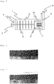
- the results of evaluation performed by the methods described above are shown in Table 1. Further, Fig. 6 shows a photograph of the rotor after the evaluation of productivity; on this rotor, no traces of beads abrasion were seen.
- Example 1 The procedure was similar to that of Example 1 except that the material of the stirring blade was changed to zirconia with a Young's modulus of 200 GPa. The results are shown in Table 1.
- Example 2 The procedure was similar to that of Example 2 except that the separation mechanism was changed to the one adopting a rotary screen system, the thickness t of the protrusion 10 of the stirring blade 3' nearest to the outlet 6 was changed to 34 mm, and the distance L from the outlet side of the portion excluding the protrusions of the stirring blade nearest to the outlet to the rear end of the cylindrical vessel was changed to 39 mm (see Fig. 3 ). The results are shown in Table 1.
- Example 1 The procedure was similar to that of Example 1 except that the material of the stirring blade was changed to low density polyethylene (LDPE) with a Young's modulus of 0.3 GPa. The results are shown in Table 1.
- LDPE low density polyethylene
- Example 1 The procedure was similar to that of Example 1 except that the material of the stirring blade was changed to high density polyethylene (HDPE) with a Young's modulus of 0.7 GPa. The results are shown in Table 1.
- HDPE high density polyethylene
- Example 2 The procedure was similar to that of Example 1 except that the thickness t of the protrusion of the stirring blade nearest to the outlet was changed to 15 mm. The results are shown in Table 2.
- Example 2 The procedure was similar to that of Example 1 except that the thickness t of the protrusion of the stirring blade nearest to the outlet was changed to 11 mm. The results are shown in Table 2.
- Example 2 The procedure was similar to that of Example 1 except that the thickness t of the protrusion of the stirring blade nearest to the outlet was changed to 10 mm and the diameter d of the media particle was changed to 1.0 mm. The results are shown in Table 2.
- Example 2 The procedure was similar to that of Example 1 except that the distance r from the center of the stirring blade to the end on the outer peripheral side of the protrusion was changed to 69 mm. The results are shown in Table 2.
- Example 2 The procedure was similar to that of Example 1 except that the distance r from the center of the stirring blade to the end on the outer peripheral side of the protrusion was changed to 47 mm. The results are shown in Table 2.
- Example 2 The procedure was similar to that of Example 1 except that the distance r from the center of the stirring blade to the end on the outer peripheral side of the protrusion was changed to 23 mm. The results are shown in Table 2.
- Fig. 7 shows a photograph of the rotor after the evaluation of productivity; on this rotor, traces of beads abrasion were seen.
- Example 3 The procedure was similar to that of Example 1 except that the thickness t of the protrusion of the stirring blade nearest to the outlet was changed to 4 mm. The results are shown in Table 3.
- Example 3 The procedure was similar to that of Example 1 except that the thickness t of the protrusion of the stirring blade nearest to the outlet was changed to 5 mm and the diameter d of the media particle was changed to 2.0 mm. The results are shown in Table 3.
- Example 3 The procedure was similar to that of Example 1 except that the separation mechanism was changed to the one adopting a fixed screen system, the thickness t of the protrusion 10 of the stirring blade 3' nearest to the outlet 6 was set to 50 mm, the distance L from the outlet side of the portion excluding the protrusions of the stirring blade nearest to the outlet to the rear end of the cylindrical vessel was set to 52 mm, and a structure in which the protrusion 10 is extended so as to cover a screen 7' was employed (see Fig. 5 ). The results are shown in Table 3. The protrusion of the stirring blade was longer, and the area of the effective dispersing region was reduced; consequently, the residence time to obtain a desired particle size was longer, and this resulted in a reduction in productivity.
- Example 1 [Table 1] [Table 1] Example 1 Example 2 Example 3 Example 4 Example 5 Configuration of media-type disperser Thickness t of protrusion (mm) 19 19 34 19 19 Distance L from stirring blade to rear end of cylindrical vessel (mm) 24 24 39 24 24 Diameter d of media particle (mm) 0.5 0.5 0.5 0.5 0.5 0.5 0.5 Distance r from center of stirring blade to protrusion (mm) 74 74 74 74 74 74 Number of protrusions 4 4 4 4 Separation mechanism Gap separator system Gap separator system Screen system Gap separator system Gap separator system Stirring blade Material UHM w PE Zirconia Zirconia LDPE HDPE Young's modulus (GPa) 0.5 200 200 0.3 0.7 Results of flow analysis Density ⁇ of media particles (kg/m 3 ) 4000 4000 4000 4000 4000 4000 4000 Average relative speed Vn (m/s) 4.3 4.3 4.3 4.3 4.3 4.3 4.3 4.3 Average speed Vr
- the present invention can be suitably used to finely disperse a liquid mixture containing filler particles and a solvent; for example, can be suitably used for a dispersion of slurry for a separator of a battery, or the like.
Landscapes
- Chemical & Material Sciences (AREA)
- Chemical Kinetics & Catalysis (AREA)
- Engineering & Computer Science (AREA)
- Food Science & Technology (AREA)
- Dispersion Chemistry (AREA)
- Crushing And Grinding (AREA)
- Mixers Of The Rotary Stirring Type (AREA)
Abstract
Description
- The present invention relates to a media-type disperser and a method for producing a liquid dispersion.
- These days, media-type dispersers are frequently used as dispersers that finely disperse a liquid dispersion. A typical media-type disperser is one in which stirring blades (stirring discs) and media particles are housed in a cylindrical vessel; however, the abrasion of the stirring blade and the inner wall of the vessel has been a problem. Further, in general, a means for dividing of a liquid dispersion and media particles, such as a screen or a gap separator, is provided in a cylindrical vessel of a media-type disperser; however, there has been a problem of the clogging of the screen etc. due to media particles.
- As a means for improving the abrasion resistance of a stirring blade placed in a cylindrical vessel and the inner wall of the vessel, for example, forming them out of a high molecular material having abrasion resistance and impact resistance is proposed (for example, see Patent Literature 1). Further, as a method for suppressing the clogging of a screen due to media particles, for example, a method is proposed in which the edge end of the stirring blade located most on the outlet side is extended up to near the side surface on the exit side of the outlet, thereby media that have flowed in around a screen section are returned to the dispersing chamber by the rotation of the edge end, and thus a media separating chamber in which practically no media exist around the screen section is created (for example, see Patent Literature 2).
-
- Patent Document 1: Japanese Patent Laid-open Publication No.
H7-24287 - Patent Document 2: Japanese Patent Laid-open Publication No.
2000-171931 - However, even in the technology described in
Patent Document 1, as the viscosity of the liquid dispersion becomes higher, the fluidity of the media particles becomes lower around the screen or the gap separator that separates the media particles from the liquid mixture, and the speed difference between the screen or the gap separator and the media particles becomes larger; hence, there has been a problem of the screen or the gap separator being damaged by abrasion. On the other hand, in the technology described inPatent Document 2, since practically no media particles exist around the screen section, damage due to abrasion of the screen or the gap separator is suppressed; however, the dispersing region in the cylindrical vessel cannot be utilized effectively, and hence there has been a problem of reduction in productivity. - Thus, an object of the present invention is to provide a media-type disperser and a method for producing a liquid dispersion that can improve productivity while suppressing damage due to abrasion of a screen or a gap separator.
- In order to solve this object, the present invention mainly include any of the following configurations.
- (1) A media-type disperser that is a media-type wet disperser in which a drive shaft, a plurality of stirring blades that are arranged on the drive shaft and are simultaneously rotatable by rotation of the drive shaft, and media particles are housed in a cylindrical vessel having a supply port of a liquid mixture and an outlet of a liquid dispersion, in which the stirring blade nearest to the outlet has a protrusion in a direction parallel to the drive shaft, and a thickness t (mm) of the protrusion, a diameter d (mm) of the media particle, and a distance L (mm) from the outlet side of the stirring blade nearest to the outlet to a rear end of the cylindrical vessel satisfy Formula (1) below,

- (2) A method for producing a liquid dispersion includes a step of dispersing a liquid mixture containing at least filler particles each with a Mohs hardness of more than or equal to 4 and a solvent by using the media-type disperser.
- (3) A method for producing a liquid dispersion, the method being a method of producing a liquid dispersion by stirring a liquid mixture by means of media particles and separating the media particles from the liquid mixture by means of a gap between a rotor being rotated by rotation of a drive shaft and a stator, in which an average relative speed Vn between a speed of the rotor and a speed in a rotation direction of the media particle existing in a position up to 1 mm from the stator toward the rotor in a direction parallel to the drive shaft satisfies Formula (2) below,

- According to the present invention, productivity can be improved while damage due to abrasion of a screen or of a gap separator in a media-type disperser is suppressed.
-
-
Fig. 1 is a schematic diagram showing an embodiment of a media-type disperser of the present invention. -
Fig. 2 is an enlarged view of a stirring blade nearest to an outlet and the neighborhood of a gap separator in an embodiment of a media-type disperser of the present invention. -
Fig. 3 is a schematic diagram showing another embodiment of a media-type disperser of the present invention. -
Fig. 4 is a schematic diagram showing an example of a conventional media-type disperser. -
Fig. 5 is a schematic diagram showing another example of a conventional media-type disperser. -
Fig. 6 is a photograph of a rotor on which there are no traces of beads abrasion. -
Fig. 7 is a photograph of a rotor on which there are traces of beads abrasion. - In a media-type disperser of the present invention, a drive shaft, a plurality of stirring blades (stirring discs) that are arranged on the drive shaft and are simultaneously rotatable by the rotation of the drive shaft, and media particles are housed in a cylindrical vessel having a supply port of a liquid mixture and an outlet of a liquid dispersion. Here, in the present invention, the liquid mixture refers to a source material mixture that is passed through the media-type disperser, and the liquid dispersion refers to a dispersion of the source material mixture that has been passed through the media-type disperser, excluding the media. In the media-type disperser of the present invention, the stirring blade nearest to the outlet has a protrusion in a direction parallel to the drive shaft; and the thickness t (mm) of the protrusion, the diameter d (mm) of the media particle, and the distance L (mm) from the outlet side of the stirring blade nearest to the outlet to the rear end of the cylindrical vessel satisfy Formula (1) below.

-
Fig. 1 shows a schematic diagram showing an embodiment of the media-type disperser of the present invention. The media-type disperser includes adrive shaft 2 in acylindrical vessel 1, and includes, on thedrive shaft 2, a plurality of stirringblades 3 that are simultaneously rotatable by the rotation of thedrive shaft 2. Here, the center axis of thecylindrical vessel 1 and thedrive shaft 2 are preferably coaxial. Each of the plurality of stirringblades 3 may basically be a platelike body of a circle or the like that is rotated by the rotation of thedrive shaft 2; among these, a stirring blade 3' nearest to anoutlet 6 has aprotrusion 10 protruding in a direction parallel to thedrive shaft 2. The protrusion is preferably provided on the outlet side of the stirring blade nearest to the outlet. Further, arotor 7 rotatable by the rotation of thedrive shaft 2 and astator 8, which is a fixed ring, are provided still more on theoutlet 6 side than the stirring blade 3' nearest to theoutlet 6 in thecylindrical vessel 1. Thestator 8 is integrated with ahead cover 9 that is provided in a liquid-tight manner to an end portion on theoutlet 6 side of thecylindrical vessel 1. Further, not-illustrated media particles are provided in thecylindrical vessel 1. - In such a media-type disperser, a liquid mixture is caused to flow from a
supply port 4 into a dispersingchamber 5 in which media particles are put, is finely dispersed by the collision etc. of media particles accelerated by the stirringblades 3 that are rotating and becomes a liquid dispersion, and is discharged from theoutlet 6 to the outside of thecylindrical vessel 1. At this point, only the liquid dispersion passes through the gap between therotor 7 and thestator 8, and thereby the liquid dispersion and the media particles can be separated. InFig. 1 , the arrow indicates the flowing direction of the liquid mixture and the liquid dispersion. - In a media-type disperser of the present invention like the above, the stirring blade nearest to the outlet of a liquid dispersion has a protrusion; thereby, the speed of media particles in a direction parallel to the rotation direction of the drive shaft is increased, and the difference between the peripheral speed of the rotor being rotated by the rotation of the drive shaft and the speed in a direction parallel to the rotation direction of the media particle in the vicinity of the rotor can be reduced; thus, damage due to abrasion of the screen or the gap separator can be suppressed.
- Specifically, for example, when stirring a liquid mixture by means of media particles and separating the media particles from the liquid mixture by means of the gap between the rotor and the stator to obtain a liquid dispersion, the average relative speed Vn between the speed in the rotation direction of the media particle existing in a position up to 1 mm from the stator toward the rotor in a direction parallel to the drive shaft and the speed of the rotor being rotated by the rotation of the drive shaft can be caused to satisfy the relation of Formula (2) below.

- The speed of the media particle encompasses the speeds of all the media particles existing in the position described above and the speed of the rotor refers to the speed on the outer peripheral surface of the rotor, and the average value of the relative speeds between them is taken as the average relative speed Vn. However, when the speeds of the media particles existing in the position described above are not greatly different between the inner side and the outer side with respect to the diameter direction of the drive shaft and representation by media particles in a partial region alone is allowable, such representation may be employed.
- Although the relation of Formula (2) above can be achieved also by reducing the viscosity of the liquid mixture, a dispersing apparatus like that mentioned above allows the relation to be achieved even when it is impossible to reduce the viscosity of the liquid mixture. Then, the frictional resistance between media particles and the stator etc. can be minimized, and the damage of the rotor, the stator, etc. can be suppressed.
-
Fig. 2 shows an enlarged view of the stirring blade nearest to the outlet and of the neighborhood of the gap separator in an embodiment of the media-type disperser of the present invention. In the media-type disperser of the present invention, the thickness t (mm) of the protrusion possessed by the stirring blade nearest to the outlet, the diameter d (mm) of the media particle, and the distance L (mm) from the outlet side of the stirring blade nearest to the outlet to the rear end of the cylindrical vessel satisfy Formula (1) below. Here, the thickness t of the protrusion is the length in a direction parallel to the drive shaft, and refers to the thickness of the thickest portion in a direction parallel to the drive shaft. The diameter d of the media particle refers to the number average value of the long diameters of 200 randomly selected media particles. The distance L from the outlet side of the stirring blade nearest to the outlet to the rear end of the cylindrical vessel refers to the distance from the outlet side of the portion excluding theprotrusion 10 of the stirring blade 3' nearest to the outlet to thehead cover 9.
- Studies by the present inventors have experimentally found out that, by a protrusion having a thickness t satisfying Formula (1) above, the speed of media particles in a direction parallel to the rotation direction of the stirring blade is increased and the difference between the peripheral speed of the rotor being rotated by the rotation of the drive shaft and the speed in a direction parallel to the rotation direction of the media particle in the vicinity of the rotor can be reduced, and thus damage due to abrasion of the screen or the gap separator (the
rotor 7 and thestator 8 inFigs. 1 and 2 ) can be suppressed. If the thickness t of the protrusion is smaller than 10d, the effect of the protrusion is not sufficiently obtained, and hence damage due to abrasion of the screen or the gap separator is likely to occur. On the other hand, if the thickness t of the protrusion is larger than L - 10d, media particles are likely to be caught in the gap between the protrusion of the stirring blade and the gap separator, and the fluidity of media particles is reduced and the internal pressure rises; consequently, productivity is reduced. - The thickness t of the protrusion is preferably more than or equal to L/2. By setting the thickness t of the protrusion to more than or equal to L/2, the speed in a direction parallel to the rotation direction of the media particle is made larger, and damage due to abrasion of the screen or the gap separator can be suppressed more.
- The distance L from the outlet side of the stirring blade nearest to the outlet to the rear end of the cylindrical vessel is preferably more than or equal to the length of a separation mechanism in a direction parallel to the drive shaft and less than or equal to 1.2 times the length of the separation mechanism, in order to sufficiently obtain the effect of the protrusion. The length of the separation mechanism is the length in the direction of the drive shaft of a rotor in the case of the separation mechanism adopting a gap separator system like that shown in
Figs. 1 and 2 , and is the length in the direction of the drive shaft of a screen in the case of the separation mechanism adopting a screen system. - In the present invention, the thickness t (mm) of the protrusion and the distance L (mm) from the outlet side of the portion excluding the protrusion of the stirring blade nearest to the outlet to the rear end of the cylindrical vessel can be measured using vernier calipers. The diameter d (mm) of the media particle can be found by observing media particles with a microscope with a magnification of 100 times, measuring the long diameters of 200 randomly selected media particles, and calculating the number average value of them.
- The protrusion may have any length in the diameter direction of the drive shaft, but it is preferable that the end on the outer peripheral side of the protrusion be provided more on the outer side than the middle position between the center and the outermost periphery of the stirring blade nearest to the outlet. When the end on the outer peripheral side of the protrusion is located more on the outer side than the middle position between the center and the outermost periphery of the stirring blade, the angular velocity of the protrusion is large, and the speed of media particles in a direction parallel to the rotation direction of the protrusion is large; thus, the effect of the protrusion can be sufficiently obtained.
- It is preferable that a plurality of protrusions be provided. When the outer peripheral side of the protrusion has a larger area on the same circumference, the effect of the protrusion can be obtained more, but the passage of the liquid dispersion is reduced and a rise in the internal pressure is caused; thus, the protrusion may be divided into a plurality of pieces, and thereby a rise in the internal pressure can be suppressed. The protrusion more preferably has a tapered shape from the inner side to the outer side in the diameter direction of the stirring blade.
- In the present invention, the media-type disperser preferably has, in the cylindrical vessel, a separation mechanism that separates the media particles and the liquid dispersion. Examples of the separation mechanism include a gap separator, a screen, a slit, a mesh, and the like. Among these, a gap separator system is preferable. Here, the gap separator system is a system that includes a rotor rotatable by the rotation of the drive shaft and a stator, which is a fixed ring, and that separates the liquid dispersion and the media particles by only the liquid dispersion passing through the gap between the rotor and the stator. The separation mechanism adopting a gap separator system can shorten the distance between the stirring blade nearest to the outlet and the separation mechanism; thus, the dispersing region in the cylindrical vessel can be utilized as much as possible, and productivity can be improved more.
- In the present invention, examples of the material of the stirring blade include super hard alloy materials, ceramic materials, metals, materials each with a Young's modulus of 0.4 to 0.6 GPa, and the like. Examples of the super hard alloy material include WC-Co-based alloys, WC-TiC-Co-based alloys, WC-TaC-Co-based alloys, WC-TiC-TaC-Co-based alloys, and the like. Examples of the ceramic material include zirconia, alumina, silicon carbide, aluminum nitride, sialon, zirconia toughened alumina, and the like. Zirconia and zirconia toughened alumina are preferable from the viewpoints of abrasion resistance, the thermal conductivity, and the coefficient of thermal expansion. Examples of the metal include stainless steel, carbon steel, and the like.
- From the viewpoint of more improving abrasion resistance to media particles, filler particles in a liquid mixture, etc., it is preferable that at least part of the stirring blade be made of a material with a Young's modulus of 0.4 to 0.6 GPa, and it is more preferable that a portion that media particles and a liquid mixture are in contact with be made of a material with a Young's modulus of 0.4 to 0.6 GPa. By using a material with a Young's modulus of 0.4 to 0.6 GPa, the abrasion of the stirring blade can be suppressed more, and the dispersibility of a liquid dispersion can be stabilized more. Here, the Young's modulus can be measured by a method prescribed by JIS K7161-1:2014 in the case of resin materials and by a method prescribed by JIS R1602:1995 in the case of ceramic and metal-based materials.
- Examples of the material with a Young's modulus of 0.4 to 0.6 GPa include ultrahigh molecular weight polyethylene, polytetrafluoroethylene, and the like. Among these, ultrahigh molecular weight polyethylene is more preferable because it is light in weight and excellent in maintainability. Here, the ultrahigh molecular weight polyethylene refers generally to polyethylene with a weight-average molecular weight of more than or equal to one million. The molecular weight of the ultrahigh molecular weight polyethylene is preferably less than or equal to seven million.
- The material of a portion of the stirring blade that media particles and a liquid mixture are not in contact with (for example, a portion other than the surface of the stirring blade) is preferably a metal and more preferably stainless steel from the viewpoint of mechanical strength.
- Also the material of the drive shaft for rotating the stirring blade is preferably a metal from the viewpoint of mechanical strength. Those given as examples of the material of the stirring blade are given as the metal. However, the surface of the drive shaft is preferably covered with a ceramic or ultrahigh molecular weight polyethylene from the viewpoint of suppressing the mixing of metal powder due to abrasion into a liquid dispersion. For similar reasons, a cover of a ceramic or ultrahigh molecular weight polyethylene may be provided on a metal drive shaft.
- Examples of the material of the inner wall of the cylindrical vessel include super hard alloy materials, ceramic materials, stainless steel, materials each with a Young's modulus of 0.4 to 0.6 GPa, and the like. It is preferable that a ceramic material be selected when high thermal conductivity is required and a material with a Young's modulus of 0.4 to 0.6 GPa be selected when higher abrasion resistance is required. Those given as examples of the respective types of material of the stirring blade and the like are given as the super hard alloy material, the ceramic material, and the material with a Young's modulus of 0.4 to 0.6 GPa.
- It is preferable that the inner wall of the cylindrical vessel have a structure capable of introducing a cooling or heating medium and that dispersion be performed while the temperature of the liquid dispersion is controlled by the cooling or heating medium. For example, in the case where the liquid mixture and the liquid dispersion have reactivity, thermal degradability, etc., a cooling medium may be used to keep the temperature of the liquid dispersion less than or equal to a certain temperature, and thereby the quality reduction of the liquid dispersion can be suppressed.
- The media particle receives strong collision energy by the rotation of the stirring blade; thus, particles of zirconia, alumina, or the like are suitably used from the viewpoint of abrasion resistance. In the case of having the separation mechanism adopting a gap separator system, the gap between the rotor and the stator is generally more than or equal to 0.1 mm; thus, the diameter d of the media particle is preferably more than or equal to 0.3 mm from the viewpoint of the protection of the equipment.
- The media-type disperser of the present invention preferably has a metering pump upstream of the supply port of a liquid mixture, and can perform continuous dispersion treatment by continuously supplying a liquid mixture. Further, the dispersibility of a liquid dispersion can be stabilized by quantitatively supplying a liquid mixture. Examples of the metering pump include centrifugal pumps such as a single-stage turbine pump and a bore hole, propeller pumps such as an axial flow pump and a mixed flow pump, viscous pumps such as a single-stage centrifugal pump and a multi-stage centrifugal pump, reciprocating pumps such as a lateral piston pump, a vertical piston pump, a horizontal piston pump, a horizontal plunger pump, a vertical plunger pump, a diaphragm pump, a tube pump, and a wing pump, rotary pumps such as an external gear pump, an internal gear pump, an eccentric screw pump, a vane pump, and a roller pump, and the like.
- Next, a method for producing a liquid dispersion of the present invention is described. As described above, in the case where a conventional media-type disperser is used, as the viscosity of the liquid dispersion becomes higher, the screen or the gap separator has tended to be easily damaged by abrasion. The media-type disperser of the present invention can suppress damage due to abrasion of the screen or the gap separator, and can therefore be suitably used for the production of a liquid dispersion with high viscosity. Thus, the method preferably has a step of dispersing a liquid mixture containing at least filler particles and a solvent by using the media-type disperser described above.
- Examples of filler particles include calcium carbonate particles, calcium phosphate particles, amorphous silica particles, crystalline glass filler, kaolin particles, talc particles, titania particles, alumina particles, silica-alumina composite oxide particles, barium sulphate particles, calcium fluoride particles, lithium fluoride particles, zeolite particles, molybdenum sulfide particles, mica particles, boehmite particles, zirconia particles, magnesium oxide particles, titanium oxide particles, silicon nitride, and the like. It is preferable that, in the liquid dispersion, the filler particles contained in the liquid dispersion be sufficiently dispersed up to the primary particle sizes while maintaining required particle sizes and surface characteristics. The Mohs hardness of the filler particle is preferably more than or equal to 4 in order to suppress surface modification due to pulverization of the filler particle by a media particle. Examples of the filler particle with a Mohs hardness of more than or equal to 4 include alumina particles, amorphous silica particles, magnesium oxide particles, titanium oxide particles, silicon nitride particles, zirconia particles, and the like.
- Here, the Mohs hardness shows the hardness to minerals, and can be measured using a commercially available 10-grade Mohs hardness meter. Specifically, a material of interest and each of the minerals used as the ranks in the 10-grade Mohs hardness meter are rubbed together, and then the presence or absence of a flaw is visually observed. In the case where both of the material and the mineral of a specific grade are flawed or neither of them is flawed, the same grade as the grade of the mineral of the specific grade used is taken as the Mohs hardness of the material. In the case where only either of the material and the mineral of a specific rank is flawed among the minerals of all the grades, a value 0.5 higher than the grade of the mineral of the highest grade, among those used as the grades in the 10-stage Mohs hardness meter, by which the material is not flawed is taken as the Mohs hardness of the material.
- In the case where the liquid dispersion is used for a member that electrical insulating properties are required of, the filler particles are preferably electrical insulating particles. Here, the electrical insulating properties mean that the volume resistivity of the material is more than or equal to 1014 Ω·cm. The volume resistivity of the material can be measured by a method prescribed by JIS C2141:1992. Examples of electrical insulating particles include alumina particles, amorphous silica particles, magnesium oxide particles, silicon nitride particles, zirconia particles, and the like.
- Examples of the solvent include Cellosolves such as methyl Cellosolve, ethyl Cellosolve, and butyl Cellosolve; alcohols such as isopropyl alcohol, methyl alcohol, ethyl alcohol, butyl alcohol, normal-propyl alcohol, benzyl alcohol, terpineol, and 3-methoxy-3-methyl-1-butanol; ketones such as methyl ethyl ketone, dioxane, acetone, cyclohexanone, cyclopentanone, γ-butyrolactone, and N-methyl-2-pyrrolidone; esters such as ethyl lactate, methyl acetate, ethyl acetate, isopropyl acetate, normal-propyl acetate, isobutyl acetate, normal-pentyl acetate, 3-methoxy-3-methyl-1-butanol, 3-methoxy-3-methyl-butyl acetate, propylene glycol 1-monomethyl ether 2-acetate, diethylene glycol monobutyl ether acetate, ethylene glycol monobutyl ether acetate, 2,2,4-trimethyl-1,3-pentanediol monoisobutyrate, and 2,2,4-trimethyl-1,3-pentanediol diisobutyrate; hydrocarbons such as hexane, cyclohexane, toluene, and xylenes; and water and the like. Two or more of these may be contained.
- As described above, as the viscosity of the liquid dispersion becomes higher, the screen or the gap separator tends to be easily damaged by abrasion. Thus, the present invention can obtain a more significant effect and is preferable particularly when it is attempted to obtain a liquid dispersion with a viscosity of more than or equal to 100 mPa·s, etc.
- The evaluation of the amount of abrasion of the separation mechanism and the damage of the separation mechanism in each of Examples and Comparative Examples was performed by flow analysis using Eulerian multiphase flow (Granular model). The conditions used for the flow analysis are as follows.
- Density of the liquid mixture: 1,130 kg/m3
- Viscosity of the liquid mixture (that is, the viscosity of the liquid dispersion): 1,800 mPa·s
- True density of media particles: 4,000 kg/m3
- Bulk density of media particles: 2,400 kg/m3
- Rate of filling of media particles in the cylindrical vessel: 80 volume%
- Rate of rotation of the drive shaft: 1,239 rpm
- Diameter of the stirring blade: 185 mm
- Thickness of the stirring blade: 10 mm
- Inner diameter of the cylindrical vessel: 220 mm
- Full length of the cylindrical vessel: 175 mm
- Diameter of the rotation ring (rotor) of the separation mechanism: 125 mm
- Rate of supply of the liquid mixture: 75 kg/hr.
- The evaluation was performed by flow analysis. For each of Examples and Comparative Examples, the amount E of abrasion of the separation mechanism was calculated by Formula (3) below from the true density ρ (kg/m3) of media particles in the vicinity of the separation mechanism, the average relative speed Vn (m/s) between the speed of the rotor and the speed in the rotation direction of the media particle in the vicinity of the separation mechanism, the average speed Vr (m/s) in a direction perpendicular to the drive shaft of the media particle in the vicinity of the separation mechanism, the volume fraction α (%) of media particles in the vicinity of the separation mechanism, and a proportionality constant A. However, a relative value with respect to the amount of abrasion of Comparative Example 1 was used on the assumption that the amount of abrasion of Comparative Example 1 was 100. Here, the vicinity of the separation mechanism was, in the case of a gap separator system, a position that was in the cylindrical vessel and up to 1 mm from the stator toward the stirring blade in a direction parallel to the drive shaft, and was, in the case of a screen system, a position that was in the cylindrical vessel and up to 1 mm from the head cover toward the stirring blade in a direction parallel to the drive shaft.

- The abrasion of the separation mechanism was evaluated by the criteria mentioned below from the value of the amount E of abrasion of the separation mechanism.
- E ≤ 90: ⊚
90 < E ≤ 95: o
95 < E: × - The evaluation was performed by flow analysis. For each of Examples and Comparative Examples, the amount W of the liquid mixture passing through the media-type disperser until damage occurred was calculated by Formula (4) below, which was found experimentally. However, a relative value with respect to the value of Comparative Example 1 of 100 was used.

- The damage of the separation mechanism was evaluated by the criteria mentioned below from the value of the amount W of the liquid mixture passing through the media-type disperser until damage occurred.
- 111 ≤ W: ⊚
105 ≤ W < 111: o
W < 105: × - A disc with a diameter of 80 mm and a thickness of 10 mm was produced using the material for forming the stirring blade used in each of Examples and Comparative Examples. The obtained disc was applied to stirring for 30 hours at a rate of rotation of 2,000 rpm in a container in which 400 g of water and 1,440 g of media particles with a true density of 4,000 kg/m3 were housed, using Three-One Motor ST-200 manufactured by AS ONE Corporation. For the disc after stirring, the presence or absence of abrasion or deformation was visually observed, and the abrasion of the stirring blade was evaluated by the criteria mentioned below.
- There was no abrasion/deformation: o
There was abrasion: Δ
There was deformation: ×. - A liquid mixture in which a polyvinylidene fluoride-hexafluoropropylene copolymer (PVdF/HFP = 92/8 (weight ratio), with a weight-average molecular weight of one million), alumina particles (average particle size: 0.5 µm; volume resistivity: 1015 Ω•cm), and N-methyl-2-pyrrolidone were blended at a weight ratio of 5:12:83, respectively, was passed through a media-type disperser of the configuration shown in each of Examples and Comparative Examples, via a diaphragm pump. The stirring blade was rotated under the condition of a peripheral speed of 12 m/s, and productivity was evaluated by the criteria mentioned below from the residence time in the disperser vessel until the average particle size of the alumina particle in the liquid dispersion reached 0.5 µm. The average particle size of the alumina particle in the liquid dispersion was measured using MT-3300 manufactured by MicrotracBEL Corp.
- The residence time being less than 10 minutes: o
The residence time being more than or equal to 10 minutes: ×. - Traces of beads abrasion on the rotor after 0.8 t of a liquid mixture was continuously passed under the same conditions as those of the evaluation of productivity described above were evaluated by visual inspection.
- The shape of the stator after 0.8 t of a liquid mixture was continuously passed under the same conditions as those of the evaluation of productivity described above was measured using VR-3000 manufactured by KEYENCE Corporation, and was evaluated by the cross-sectional area of the abrasion portion.
- In a media-type disperser of the configuration shown in
Figs. 1 and 2 , the thickness t of the protrusion of the stirring blade nearest to the outlet was set to 19 mm, the diameter d of the media particle was set to 0.5 mm, the distance L from the outlet side of the portion excluding the protrusions of the stirring blade nearest to the outlet to the rear end of the cylindrical vessel was set to 24 mm, the distance r from the center of the stirring blade to the end on the outer peripheral side of the protrusion was set to 74 mm, and the number of protrusions of the stirring blade was set to 4; and flow analysis was performed using Eulerian multiphase flow. Here, as shown inFig. 1 , thehead cover 9 was located at the rear end of thecylindrical vessel 1. Ultrahigh molecular weight polyethylene (UHMwPE) with a Young's modulus of 0.5 GPa was used as the material of the stirring blade. The results of evaluation performed by the methods described above are shown in Table 1. Further,Fig. 6 shows a photograph of the rotor after the evaluation of productivity; on this rotor, no traces of beads abrasion were seen. - The procedure was similar to that of Example 1 except that the material of the stirring blade was changed to zirconia with a Young's modulus of 200 GPa. The results are shown in Table 1.
- The procedure was similar to that of Example 2 except that the separation mechanism was changed to the one adopting a rotary screen system, the thickness t of the
protrusion 10 of the stirring blade 3' nearest to theoutlet 6 was changed to 34 mm, and the distance L from the outlet side of the portion excluding the protrusions of the stirring blade nearest to the outlet to the rear end of the cylindrical vessel was changed to 39 mm (seeFig. 3 ). The results are shown in Table 1. - The procedure was similar to that of Example 1 except that the material of the stirring blade was changed to low density polyethylene (LDPE) with a Young's modulus of 0.3 GPa. The results are shown in Table 1.
- The procedure was similar to that of Example 1 except that the material of the stirring blade was changed to high density polyethylene (HDPE) with a Young's modulus of 0.7 GPa. The results are shown in Table 1.
- The procedure was similar to that of Example 1 except that the thickness t of the protrusion of the stirring blade nearest to the outlet was changed to 15 mm. The results are shown in Table 2.
- The procedure was similar to that of Example 1 except that the thickness t of the protrusion of the stirring blade nearest to the outlet was changed to 11 mm. The results are shown in Table 2.
- The procedure was similar to that of Example 1 except that the thickness t of the protrusion of the stirring blade nearest to the outlet was changed to 10 mm and the diameter d of the media particle was changed to 1.0 mm. The results are shown in Table 2.
- The procedure was similar to that of Example 1 except that the distance r from the center of the stirring blade to the end on the outer peripheral side of the protrusion was changed to 69 mm. The results are shown in Table 2.
- The procedure was similar to that of Example 1 except that the distance r from the center of the stirring blade to the end on the outer peripheral side of the protrusion was changed to 47 mm. The results are shown in Table 2.
- The procedure was similar to that of Example 1 except that the distance r from the center of the stirring blade to the end on the outer peripheral side of the protrusion was changed to 23 mm. The results are shown in Table 2.
- The procedure was similar to that of Example 1 except that no protrusion was provided on the stirring blade nearest to the outlet (see
Fig. 4 ). The results are shown in Table 3. Further,Fig. 7 shows a photograph of the rotor after the evaluation of productivity; on this rotor, traces of beads abrasion were seen. - The procedure was similar to that of Example 1 except that the thickness t of the protrusion of the stirring blade nearest to the outlet was changed to 4 mm. The results are shown in Table 3.
- The procedure was similar to that of Example 1 except that the thickness t of the protrusion of the stirring blade nearest to the outlet was changed to 5 mm and the diameter d of the media particle was changed to 2.0 mm. The results are shown in Table 3.
- The procedure was similar to that of Example 1 except that the separation mechanism was changed to the one adopting a fixed screen system, the thickness t of the
protrusion 10 of the stirring blade 3' nearest to theoutlet 6 was set to 50 mm, the distance L from the outlet side of the portion excluding the protrusions of the stirring blade nearest to the outlet to the rear end of the cylindrical vessel was set to 52 mm, and a structure in which theprotrusion 10 is extended so as to cover a screen 7' was employed (seeFig. 5 ). The results are shown in Table 3. The protrusion of the stirring blade was longer, and the area of the effective dispersing region was reduced; consequently, the residence time to obtain a desired particle size was longer, and this resulted in a reduction in productivity.[Table 1] [Table 1] Example 1 Example 2 Example 3 Example 4 Example 5 Configuration of media-type disperser Thickness t of protrusion (mm) 19 19 34 19 19 Distance L from stirring blade to rear end of cylindrical vessel (mm) 24 24 39 24 24 Diameter d of media particle (mm) 0.5 0.5 0.5 0.5 0.5 Distance r from center of stirring blade to protrusion (mm) 74 74 74 74 74 Number of protrusions 4 4 4 4 4 Separation mechanism Gap separator system Gap separator system Screen system Gap separator system Gap separator system Stirring blade Material UHMw PE Zirconia Zirconia LDPE HDPE Young's modulus (GPa) 0.5 200 200 0.3 0.7 Results of flow analysis Density ρ of media particles (kg/m3) 4000 4000 4000 4000 4000 Average relative speed Vn (m/s) 4.3 4.3 4.3 4.3 4.3 Average speed Vr in direction perpendicular to drive shaft of media particle (m/s) 1.4 1.4 1. 4 1. 4 1.4 Volume fraction α of media particles (%) 48 48 48 48 48 Amount of abrasion of separation mechanism (E) ⊙ ⊙ ⊙ ⊙ ⊙ (84) (84) (84) (84) (84) Damage of separation mechanism (W) ⊙ ⊙ ⊙ ⊙ ⊙ (119) (119) (119) (119) (119) Abrasion/deformation of stirring blade ○ : absent, Δ: abrasion, ×: deformation O Δ Δ Δ Δ Productivity (average residence time (min)) ○ ○ ○ ○ ○ (7) (7) (9) (7) (7) Beads abrasion of rotor Absent - - - - Amount of abrasion of stator (mm2) 0.01 - - - - [Table 2] [Table 2] Example 6 Example 7 Example 8 Example 9 Example 10 Example 11 Configuration of media-type disperser Thickness t of protrusion (mm) 15 11 10 19 19 19 Distance L from stirring blade to rear end of cylindrical vessel (mm) 24 24 24 24 24 24 Diameter d of media particle (mm) 0.5 0.5 1.0 0.5 0.5 0.5 Distance r from center of stirring blade to protrusion (mm) 74 74 74 69 47 23 Number of protrusions 4 4 4 4 4 4 Separation mechanism Gap separator system Gap separator system Gap separator system Gap separator system Gap separator system Gap separator system Stirring blade Material UHMw PE UHMw PE UHMw PE UHMw PE UHMw PE UHMw PE Young's modulus (GPa) 0.5 0.5 0.5 0.5 0.5 0.5 Results of flow analysis Density ρ of media particles (kg/m3) 4000 4000 4000 4000 4000 4000 Average relative speed Vn (m/s) 4.5 4.8 4.8 4.5 4.8 5.0 Average speed Vr in direction perpendicular to drive shaft of media particle (m/s) 1.4 1.4 1.4 1.4 1.4 1.4 Volume fraction α of media particles (%) 48 48 48 48 48 48 Amount of abrasion of separation mechanism (E) ⊙ ○ ○ ⊙ ○ × (88) (94) (95) (88) (94) (98) Damage of separation mechanism (W) ⊙ ○ ○ ⊙ ○ × (114) (106) (105) (113) (106) (102) Abrasion/deformation of stirring blade ○ : absent, Δ: abrasion, ×: deformation ○ ○ ○ ○ ○ ○ Productivity (average residence time (min)) ○ ○ ○ ○ ○ ○ (7) (7) (7) (7) (7) (7) Beads abrasion of rotor - - - - - - Amount of abrasion of stator (mm2) - - - - - - [Table 3] [Table 3] Comparative Example 1 Comparative Example 2 Comparative Example 3 Comparative Example 4 Configuration of media-type disperser Thickness t of protrusion (mm) 0 4 5 50 Distance L from stirring blade to rear end of cylindrical vessel (mm) 24 24 24 52 Diameter d of media particle (mm) 0.5 0.5 2.0 0.5 Distance r from center of stirring blade to protrusion (mm) - 74 74 74 Number of protrusions - 4 4 4 Separation mechanism Gap separator system Gap separator system Gap separator system Screen system Stirring blade Material UHMw PE UHMw PE UHMw PE Zirconia Young's modulus (GPa) 0.5 0.5 0.5 200 Results of flow analysis Density ρ of media particles (kg/m3) 4000 4000 4000 4000 Average relative speed Vn (m/s) 5.5 5.5 5.4 10.0 Average speed Vr in direction perpendicular to drive shaft of media particle (m/s) 1.3 1.3 1.3 1.8 Volume fraction α of media particles (%) 48 48 48 48 Amount of abrasion of separation mechanism (E) × × × × (100) (100) (98) (252) Damage of separation mechanism (W) × × × × (100) (100) (102) (40) Abrasion/deformation of stirring blade ○ : absent, Δ: abrasion, x: deformation ○ ○ ○ Δ Productivity (average residence time (min)) ○ ○ ○ × (7) (7) (7) (12) Beads abrasion of rotor Present - - - Amount of abrasion of stator (mm2) 0.06 - - - - The present invention can be suitably used to finely disperse a liquid mixture containing filler particles and a solvent; for example, can be suitably used for a dispersion of slurry for a separator of a battery, or the like.
-
- 1:
- Cylindrical vessel
- 2:
- Drive shaft
- 3:
- Stirring blade
- 3':
- Stirring blade nearest to an outlet
- 4:
- Supply port
- 5:
- Dispersing chamber
- 6:
- Outlet
- 7:
- Rotor
- 7':
- Screen
- 8:
- Stator
- 9:
- Head cover
- 10:
- Protrusion
Claims (11)
- A media-type disperser that is a media-type wet disperser in which a drive shaft, a plurality of stirring blades that are arranged on the drive shaft and are simultaneously rotatable by rotation of the drive shaft, and media particles are housed in a cylindrical vessel having a supply port of a liquid mixture and an outlet of a liquid dispersion, wherein the stirring blade nearest to the outlet has a protrusion in a direction parallel to the drive shaft, and a thickness t (mm) of the protrusion, a diameter d (mm) of the media particle, and a distance L (mm) from the outlet side of the stirring blade nearest to the outlet to a rear end of the cylindrical vessel satisfy Formula (1) below,

- The media-type disperser according to claim 1, wherein the protrusion is provided such that an end on an outer peripheral side is more on an outer side than a middle position between a center and an outermost periphery of the stirring blade in a diameter direction of the drive shaft.
- The media-type disperser according to claim 1 or 2, comprising a plurality of protrusions.
- The media-type disperser according to any one of claims 1 to 3, comprising, in the cylindrical vessel, a separation mechanism adopting a gap separator system for separation between media particles and a liquid dispersion.
- The media-type disperser according to any one of claims 1 to 4, wherein at least part of the stirring blade is made of a material with a Young's modulus of 0.4 to 0.6 GPa.
- The media-type disperser according to claim 5, wherein the material with a Young's modulus of 0.4 to 0.6 GPa is ultrahigh molecular weight polyethylene.
- The media-type disperser according to any one of claims 1 to 6, wherein at least part of the drive shaft and part of the stirring blade are made of metal.
- A method for producing a liquid dispersion, comprising: a step of dispersing a liquid mixture containing at least filler particles each with a Mohs hardness of more than or equal to 4 and a solvent by using the media-type disperser according to any one of claims 1 to 7.
- The method for producing a liquid dispersion according to claim 8, wherein the filler particles are insulating particles.
- The method for producing a liquid dispersion according to claim 8 or 9, wherein a viscosity of the liquid dispersion is more than or equal to 100 mPa·s.
- A method for producing a liquid dispersion, the method being a method of producing a liquid dispersion by stirring a liquid mixture by means of media particles and separating the media particles from the liquid mixture by means of a gap between a rotor being rotated by rotation of a drive shaft and a stator, wherein an average relative speed Vn between a speed of the rotor and a speed in a rotation direction of the media particle existing in a position up to 1 mm from the stator toward the rotor in a direction parallel to the drive shaft satisfies Formula (2) below,

Applications Claiming Priority (2)
| Application Number | Priority Date | Filing Date | Title |
|---|---|---|---|
| JP2017198209 | 2017-10-12 | ||
| PCT/JP2018/036638 WO2019073835A1 (en) | 2017-10-12 | 2018-10-01 | Media type disperser and liquid dispersoid manufacturing method |
Publications (1)
| Publication Number | Publication Date |
|---|---|
| EP3695907A1 true EP3695907A1 (en) | 2020-08-19 |
Family
ID=66100706
Family Applications (1)
| Application Number | Title | Priority Date | Filing Date |
|---|---|---|---|
| EP18866551.7A Withdrawn EP3695907A1 (en) | 2017-10-12 | 2018-10-01 | Media type disperser and liquid dispersoid manufacturing method |
Country Status (5)
| Country | Link |
|---|---|
| EP (1) | EP3695907A1 (en) |
| JP (1) | JPWO2019073835A1 (en) |
| KR (1) | KR20200066282A (en) |
| CN (1) | CN111032221A (en) |
| WO (1) | WO2019073835A1 (en) |
Families Citing this family (3)
| Publication number | Priority date | Publication date | Assignee | Title |
|---|---|---|---|---|
| CN113941200B (en) * | 2021-11-30 | 2023-03-24 | 江西三合环保材料科技有限公司 | Gas-powder separation device of full-automatic plastic-powder dust-free stirrer |
| JP7111400B1 (en) | 2021-12-10 | 2022-08-02 | 淺田鉄工株式会社 | Disperser |
| CN119345711B (en) * | 2024-09-23 | 2025-09-30 | 中国科学院沈阳应用生态研究所 | A production device for cyclopentanone product |
Family Cites Families (12)
| Publication number | Priority date | Publication date | Assignee | Title |
|---|---|---|---|---|
| AU569364B2 (en) * | 1984-04-11 | 1988-01-28 | General Signal Corporation | Mixing system using impellor to decrease adhesion on blades |
| CN1005757B (en) * | 1985-04-01 | 1989-11-15 | 通用信号器公司 | Mixing system |
| GB9302911D0 (en) * | 1993-02-13 | 1993-03-31 | Tioxide Specialties Ltd | Preparation of mixed powders |
| JPH0724287A (en) | 1993-07-15 | 1995-01-27 | Inoue Seisakusho:Kk | Medium dispersion device |
| JPH11179179A (en) * | 1997-07-29 | 1999-07-06 | Ricoh Co Ltd | Dispersing machine using media |
| JP2000171931A (en) | 1998-09-30 | 2000-06-23 | Fuji Photo Film Co Ltd | Dispersed photographic solid micrograins, its manufacture, and silver halide photographic sensitive material containing it |
| JP2005111357A (en) * | 2003-10-07 | 2005-04-28 | Mitsui Mining Co Ltd | Grinder |
| JP2005169340A (en) * | 2003-12-15 | 2005-06-30 | Aimetsukusu Kk | Horizontal wet type medium agitating dispersion grinder |
| JP4281603B2 (en) * | 2004-03-31 | 2009-06-17 | 日本ゼオン株式会社 | Method for producing magenta toner |
| JP4918226B2 (en) * | 2005-03-03 | 2012-04-18 | 日本コークス工業株式会社 | Media agitation type wet crusher |
| JP5572400B2 (en) * | 2010-01-20 | 2014-08-13 | 日本コークス工業株式会社 | Media agitation type wet crusher |
| JP6011155B2 (en) * | 2012-08-24 | 2016-10-19 | 住友大阪セメント株式会社 | Circulation type media stirring mill |
-
2018
- 2018-10-01 WO PCT/JP2018/036638 patent/WO2019073835A1/en not_active Ceased
- 2018-10-01 CN CN201880052289.8A patent/CN111032221A/en not_active Withdrawn
- 2018-10-01 EP EP18866551.7A patent/EP3695907A1/en not_active Withdrawn
- 2018-10-01 JP JP2018552022A patent/JPWO2019073835A1/en active Pending
- 2018-10-01 KR KR1020207000072A patent/KR20200066282A/en not_active Withdrawn
Also Published As
| Publication number | Publication date |
|---|---|
| CN111032221A (en) | 2020-04-17 |
| KR20200066282A (en) | 2020-06-09 |
| JPWO2019073835A1 (en) | 2020-09-10 |
| WO2019073835A1 (en) | 2019-04-18 |
Similar Documents
| Publication | Publication Date | Title |
|---|---|---|
| EP3695907A1 (en) | Media type disperser and liquid dispersoid manufacturing method | |
| US8136750B2 (en) | Powder processing apparatus and powder processing system | |
| EP2789392B1 (en) | Horizontal dry mill | |
| TWI660908B (en) | Method of ball milling aluminum metaphosphate | |
| KR20210043691A (en) | Classification rotor and classifier | |
| CN203990334U (en) | The manufacturing installation of a kind of suspension and colloid | |
| JP6423988B2 (en) | Stirring mill and dispersion method of particles in slurry | |
| KR102455946B1 (en) | Dispersing Machine, Dispersing Method of Particles in Slurry, and Emulsion Manufacturing Method | |
| CN109485046B (en) | Tungsten carbide powder and preparation method thereof | |
| CN106714973A (en) | Silicon seed particles for the production of polycrystalline silicon granules in a fluidized bed reactor | |
| TW201925086A (en) | System and method for manufacturing graphene powder including a feeding unit, a rolling and pressing unit, a transport unit, and at least one impinging unit | |
| JP2020182934A (en) | Wet type bead mill | |
| JP3203625U (en) | Stirring mill | |
| EP3525935B1 (en) | Apparatus and method for bulk production of atomically thin 2-dimensional materials including graphene | |
| JP4148521B2 (en) | Spherical fine copper powder and method for producing spherical fine copper powder | |
| JP3209743U (en) | Stirring mill | |
| KR20090121679A (en) | Classifier | |
| WO2021033633A1 (en) | Organic nanoparticle production method and organic nanoparticles | |
| TWI755413B (en) | Dispersing machine and method for dispersing particles in slurry and method for producing emulsification | |
| EP2719448A1 (en) | Treatment apparatus for highly viscous fluid | |
| CN215507082U (en) | A grinder with centrifugal separator | |
| RU2314169C2 (en) | Method of the air-centrifugal classification of the powdery materials | |
| JP2007229578A (en) | Paste disperser and paste manufacturing method | |
| JP3153873U (en) | Classifier | |
| JP2008238105A (en) | Crusher |
Legal Events
| Date | Code | Title | Description |
|---|---|---|---|
| STAA | Information on the status of an ep patent application or granted ep patent |
Free format text: STATUS: THE INTERNATIONAL PUBLICATION HAS BEEN MADE |
|
| PUAI | Public reference made under article 153(3) epc to a published international application that has entered the european phase |
Free format text: ORIGINAL CODE: 0009012 |
|
| STAA | Information on the status of an ep patent application or granted ep patent |
Free format text: STATUS: REQUEST FOR EXAMINATION WAS MADE |
|
| 17P | Request for examination filed |
Effective date: 20200408 |
|
| AK | Designated contracting states |
Kind code of ref document: A1 Designated state(s): AL AT BE BG CH CY CZ DE DK EE ES FI FR GB GR HR HU IE IS IT LI LT LU LV MC MK MT NL NO PL PT RO RS SE SI SK SM TR |
|
| AX | Request for extension of the european patent |
Extension state: BA ME |
|
| DAV | Request for validation of the european patent (deleted) | ||
| DAX | Request for extension of the european patent (deleted) | ||
| STAA | Information on the status of an ep patent application or granted ep patent |
Free format text: STATUS: THE APPLICATION HAS BEEN WITHDRAWN |
|
| 18W | Application withdrawn |
Effective date: 20210416 |