EP3695874A1 - Guide wire - Google Patents
Guide wire Download PDFInfo
- Publication number
- EP3695874A1 EP3695874A1 EP17928500.2A EP17928500A EP3695874A1 EP 3695874 A1 EP3695874 A1 EP 3695874A1 EP 17928500 A EP17928500 A EP 17928500A EP 3695874 A1 EP3695874 A1 EP 3695874A1
- Authority
- EP
- European Patent Office
- Prior art keywords
- core shaft
- distal end
- coil body
- diameter portion
- guide wire
- Prior art date
- Legal status (The legal status is an assumption and is not a legal conclusion. Google has not performed a legal analysis and makes no representation as to the accuracy of the status listed.)
- Granted
Links
Images






Classifications
-
- A—HUMAN NECESSITIES
- A61—MEDICAL OR VETERINARY SCIENCE; HYGIENE
- A61M—DEVICES FOR INTRODUCING MEDIA INTO, OR ONTO, THE BODY; DEVICES FOR TRANSDUCING BODY MEDIA OR FOR TAKING MEDIA FROM THE BODY; DEVICES FOR PRODUCING OR ENDING SLEEP OR STUPOR
- A61M25/00—Catheters; Hollow probes
- A61M25/01—Introducing, guiding, advancing, emplacing or holding catheters
- A61M25/09—Guide wires
-
- A—HUMAN NECESSITIES
- A61—MEDICAL OR VETERINARY SCIENCE; HYGIENE
- A61B—DIAGNOSIS; SURGERY; IDENTIFICATION
- A61B17/00—Surgical instruments, devices or methods
- A61B17/22—Implements for squeezing-off ulcers or the like on inner organs of the body; Implements for scraping-out cavities of body organs, e.g. bones; for invasive removal or destruction of calculus using mechanical vibrations; for removing obstructions in blood vessels, not otherwise provided for
-
- A—HUMAN NECESSITIES
- A61—MEDICAL OR VETERINARY SCIENCE; HYGIENE
- A61B—DIAGNOSIS; SURGERY; IDENTIFICATION
- A61B17/00—Surgical instruments, devices or methods
- A61B17/22—Implements for squeezing-off ulcers or the like on inner organs of the body; Implements for scraping-out cavities of body organs, e.g. bones; for invasive removal or destruction of calculus using mechanical vibrations; for removing obstructions in blood vessels, not otherwise provided for
- A61B2017/22001—Angioplasty, e.g. PCTA
-
- A—HUMAN NECESSITIES
- A61—MEDICAL OR VETERINARY SCIENCE; HYGIENE
- A61B—DIAGNOSIS; SURGERY; IDENTIFICATION
- A61B17/00—Surgical instruments, devices or methods
- A61B17/22—Implements for squeezing-off ulcers or the like on inner organs of the body; Implements for scraping-out cavities of body organs, e.g. bones; for invasive removal or destruction of calculus using mechanical vibrations; for removing obstructions in blood vessels, not otherwise provided for
- A61B2017/22038—Implements for squeezing-off ulcers or the like on inner organs of the body; Implements for scraping-out cavities of body organs, e.g. bones; for invasive removal or destruction of calculus using mechanical vibrations; for removing obstructions in blood vessels, not otherwise provided for with a guide wire
- A61B2017/22042—Details of the tip of the guide wire
-
- A—HUMAN NECESSITIES
- A61—MEDICAL OR VETERINARY SCIENCE; HYGIENE
- A61M—DEVICES FOR INTRODUCING MEDIA INTO, OR ONTO, THE BODY; DEVICES FOR TRANSDUCING BODY MEDIA OR FOR TAKING MEDIA FROM THE BODY; DEVICES FOR PRODUCING OR ENDING SLEEP OR STUPOR
- A61M25/00—Catheters; Hollow probes
- A61M25/01—Introducing, guiding, advancing, emplacing or holding catheters
- A61M25/09—Guide wires
- A61M2025/09058—Basic structures of guide wires
- A61M2025/09083—Basic structures of guide wires having a coil around a core
-
- A—HUMAN NECESSITIES
- A61—MEDICAL OR VETERINARY SCIENCE; HYGIENE
- A61M—DEVICES FOR INTRODUCING MEDIA INTO, OR ONTO, THE BODY; DEVICES FOR TRANSDUCING BODY MEDIA OR FOR TAKING MEDIA FROM THE BODY; DEVICES FOR PRODUCING OR ENDING SLEEP OR STUPOR
- A61M25/00—Catheters; Hollow probes
- A61M25/01—Introducing, guiding, advancing, emplacing or holding catheters
- A61M25/09—Guide wires
- A61M2025/09133—Guide wires having specific material compositions or coatings; Materials with specific mechanical behaviours, e.g. stiffness, strength to transmit torque
- A61M2025/09141—Guide wires having specific material compositions or coatings; Materials with specific mechanical behaviours, e.g. stiffness, strength to transmit torque made of shape memory alloys which take a particular shape at a certain temperature
-
- A—HUMAN NECESSITIES
- A61—MEDICAL OR VETERINARY SCIENCE; HYGIENE
- A61M—DEVICES FOR INTRODUCING MEDIA INTO, OR ONTO, THE BODY; DEVICES FOR TRANSDUCING BODY MEDIA OR FOR TAKING MEDIA FROM THE BODY; DEVICES FOR PRODUCING OR ENDING SLEEP OR STUPOR
- A61M25/00—Catheters; Hollow probes
- A61M25/01—Introducing, guiding, advancing, emplacing or holding catheters
- A61M25/09—Guide wires
- A61M2025/0915—Guide wires having features for changing the stiffness
-
- A—HUMAN NECESSITIES
- A61—MEDICAL OR VETERINARY SCIENCE; HYGIENE
- A61M—DEVICES FOR INTRODUCING MEDIA INTO, OR ONTO, THE BODY; DEVICES FOR TRANSDUCING BODY MEDIA OR FOR TAKING MEDIA FROM THE BODY; DEVICES FOR PRODUCING OR ENDING SLEEP OR STUPOR
- A61M25/00—Catheters; Hollow probes
- A61M25/01—Introducing, guiding, advancing, emplacing or holding catheters
- A61M25/09—Guide wires
- A61M2025/09166—Guide wires having radio-opaque features
-
- A—HUMAN NECESSITIES
- A61—MEDICAL OR VETERINARY SCIENCE; HYGIENE
- A61M—DEVICES FOR INTRODUCING MEDIA INTO, OR ONTO, THE BODY; DEVICES FOR TRANSDUCING BODY MEDIA OR FOR TAKING MEDIA FROM THE BODY; DEVICES FOR PRODUCING OR ENDING SLEEP OR STUPOR
- A61M25/00—Catheters; Hollow probes
- A61M25/01—Introducing, guiding, advancing, emplacing or holding catheters
- A61M25/09—Guide wires
- A61M2025/09175—Guide wires having specific characteristics at the distal tip
Definitions
- the present invention relates to a guide wire.
- a guide wire for guiding a treatment instrument such as a balloon catheter is inserted prior to the treatment instrument.
- the distal end portion is stepwisely reduced in diameter, and thus one or more inflection points are provided. It is supposed that when the distal side of the inflection point is bent, a loop of the guide wire can be formed.
- Patent Literature 1 WO 2015/080948
- the conventional guide wire as described above when used for a lesion such as a stenosis or an occlusion in a blood vessel, excessive force may be applied to the inflection point due to large counteraction when pushing the stenosis or the like.
- the core shaft may be broken at the inflection point, and the sharp edge generated by the break causes perforation or dissociation of the blood vessel, and the bend forming the loop exceeds the inflection point to be displaced to a tapered portion or a large diameter portion in the proximal end direction. This may cause plastic deformation at a portion with high rigidity, disabling reuse of the guide wire.
- the present invention has been made in view of the above circumstances, and an object of the present invention is to provide a guide wire capable of preventing breakage of the core shaft from the tapered portion as a starting point, while suppressing displacement of the bend of the core shaft beyond the tapered portion to the proximal end direction.
- the invention relates to
- distal end direction is a direction along the axial direction of the guide wire, and indicates a direction of the side on which the distal end fixing portion is positioned relative to the large diameter portion of the core shaft.
- proximal end direction is a direction along the axial direction of the guide wire, and indicates the direction opposite to the distal end direction.
- the invention is able to provide a guide wire capable of preventing breakage of the core shaft from the tapered portion as a starting point, while suppressing displacement of the bend of the core shaft beyond the tapered portion to the proximal end direction.
- a guide wire of the invention includes a core shaft that includes a distal end portion stepwisely reducing in diameter toward a distal end direction, a coil body that is wound to cover at least a part of an outer periphery of the dimeter-reduced distal end portion, and a distal end fixing portion that fixes the distal end of the core shaft, and a distal end of the coil body to each other, in which the distal end portion of the core shaft includes a small diameter portion that is continuous with the distal end fixing portion, a large diameter portion that is positioned in a proximal end direction than the small diameter portion and has a larger outer diameter than a diameter of the small diameter portion, and a tapered portion that is continuous with the small diameter portion and the large diameter portion and gradually increases in diameter from the small diameter portion toward the large diameter portion, the core shaft and the coil body are fixed at a portion of the core shaft excluding the tapered portion, and bending rigidity FR1 of the large diameter portion, bending rigidity FR2 of the small diameter portion
- FIG. 1 is a schematic front view illustrating the first embodiment of the invention.
- a guide wire 10 of the first embodiment roughly includes a core shaft 100, a coil body 200, and a distal end fixing part 401, as illustrated in FIG. 1 .
- the core shaft 100 has a distal end portion P1stepwisely reducing in diameter toward a distal end direction.
- the distal end portion P1 of the core shaft 100 includes a small diameter portion 110 that is continuous with the distal end fixing portion 401 described later, a large diameter portion 120 that is positioned in a proximal end direction than the small diameter portion 110 and has a larger outer diameter than a diameter of the small diameter portion 110, and a tapered portion 130 that is continuous with the small diameter portion 110 and the large diameter portion 120 and gradually increases in diameter from the small diameter portion 110 toward the large diameter portion 120.
- the core shaft 100 in a state where the core shaft 100 extends in a straight line, for example, the section shape orthogonal to the axial direction of the core shaft 100 (section shape) of each of the small-diameter portion 110 and the large-diameter portion 120 is circular with a certain diameter in the axial direction, and the section shape of the tapered portion 130 is a truncated conical shape.
- the core shaft 100 includes a truncated conical connection portion 140 whose distal end is continuous with the proximal end of the large diameter portion 120, and a core shaft main body 150 whose distal end is continuous to the proximal end of the connection portion 140.
- the section shape of the above-described small diameter portion may be a flat shape (for example, see a small diameter portion 111 of a core shaft 101 illustrated in FIGS. 2A and 2B ).
- the bend of the distal end portion P11 of the core shaft 101 can be guided in a direction perpendicular to the flat surface of the small-diameter portion 111 that is easily deformed, which makes it possible to securely control the guide wire 11 during the procedure.
- the total length of the core shaft 100 is normally 1,800 to 3,000 mm, and is preferably 1,900 to 2,500.
- the axial length of the distal end portion of the core shaft 100 is normally 200 to 1,000 mm, and is preferably 300 to 850 mm.
- the outer diameter of the core shaft main body 150 is usually 0.25 to 0.5 mm, and the outer diameter of the large diameter portion 120 is usually 1/5 to 2/5 of the core shaft main body 150. Note that the outer diameter of the small diameter portion 110 is selected as described below.
- the outer diameters of the large diameter portion 120 and the small diameter portion 110, and the length of the tapered portion 130 are selected so that the bending rigidity FR1 of the large diameter portion, the bending rigidity FR2 of the small diameter portion, and the length L of the tapered portion in the axial direction of the core shaft satisfy the following expressions (1) and (2).
- the unit of L is mm.
- the ratio (FR1/FR2) of the bending rigidity of the large diameter portion 120 and the small diameter portion 110 in the above-described expression (1) is calculated as the ratio of the fourth power of the outer diameter using Hook's law, for example, if the core shaft 100 is formed homogeneously.
- the length of the small diameter portion 110 in the axial direction of the core shaft 100 is preferably not smaller than 3 mm and not larger than 15 mm. If the length of the small diameter portion 110 is 3 mm or larger, it is possible to allow sufficient bend of the small diameter portion 110, and if the length thereof is 15 mm or smaller, it is possible to prevent damages due to excessive bend of the small diameter portion 110.
- the entire length is 1,900 mm
- the axial length of the distal end portion P1 is 100 mm
- the axial length of the small diameter portion 110 is 10 mm
- the axial length of the tapered portion 130 is 1 mm
- the axial length of the large diameter portion 120 is 60 mm
- the outer diameter of the core shaft main body 150 is 0.35 mm
- the outer diameter of the large diameter portion 120 is 0.10 mm
- the outer diameter of the small diameter portion 110 is 0.04 mm, as an example.
- the material forming the core shaft 100 is not particularly limited as long as the flexibility of the small diameter portion 110 is secured and the material has antithrombogenicity and biocompatibility.
- the coil body 200 is wound so as to cover at least a part of the outer periphery of the distal end portion P1 that is reduced in diameter.
- the coil body 200 is spirally formed using one single wire so that adjacent wires come into contact with each other.
- the coil body 200 and the above-described core shaft 100 are not particularly limited as long as they are fixed at the portion of the core shaft 100 excluding the tapered portion 130.
- the portion of the core shaft 100 excluding the small diameter portion 110, the large diameter portion 120, and the tapered portion 130.
- the coil body 200 and the core shaft 100 are brazed at two positions of between a distal end of the coil body 200 and a distal end of the core shaft 100 (see the distal end fixing portion 401), and between a proximal end of the coil body 200 and the connection portion 140 of the core shaft 100 (see the brazing portion 210), for example.
- brazing material used for brazing the coil body 200 examples include metal brazing such as an Sn-Pb alloy, a Pb-Ag alloy, an Sn-Ag alloy, and an Au-Sn alloy.
- the diameter of the wires forming the coil body 200 is usually 0.01 to 0.10 mm, and is preferably 0.01 to 0.08 mm.
- the embodiment exemplifies the coil body 200 having a diameter of 0.06 mm.
- the material forming the coil body 200 is not particularly limited as long as the flexibility of the small diameter portion 110 is secured and the material has antithrombogenicity and biocompatibility.
- stainless steel such as SUS316; a superelastic alloy such as a Ni-Ti alloy; a radiopaque metal such as platinum or tungsten, or the like.
- the distal fixing portion 401 is a portion where the distal end of the core shaft 100 and the distal end of the coil body 200 are fixed to each other. Specifically, as described above, the distal end fixing portion 401 is a portion where the distal end of the core shaft 100 and the distal end of the coil body 200 are brazed, for example, and the distal end direction thereof is formed in a smoothly bent hemispherical shape by the above-described brazing material in order to prevent damages to the inner wall of a blood vessel when the guide wire 10 advances in the blood vessel.
- a doctor advances the distal end of the guide wire 10 having the bent distal end portion P1 to a closed stenosis site of a leg artery or a coronary artery. Thereafter, once the guidewire 10 is inserted in the stenosis site, the distal end portion P1 of the guide wire 10 becomes, in the stenosis lesion, a J-shape starting from the bent shape and passes through the stenosis site.
- the guide wire 10 passing through the stenosis site is stabilized in the J-shape (the J-shape does not progress to the U-shape) by the tapered portion 130, and passes the stenosis site in such a stabilized J-shape.
- a treatment instrument such as a balloon catheter or a stent is conveyed along the guide wire 10 to perform various treatments at the treatment site.
- the guide wire 10 is withdrawn from the body by retrograding through the blood vessel, and a series of procedures is completed.
- the guide wire 10 with the above-described configuration is able to prevent breakage of the core shaft 100 from the tapered portion 130 as a starting point while suppressing displacement of the bend of the core shaft 100 beyond the tapered portion 130 to the proximal end direction.
- the guidewire 10 exerts the above-described effect, and thus can be preferably used as a medical guidewire used for treatment in a blood vessel, for example.
- FIG. 3 is a schematic section view illustrating the second embodiment of the invention.
- a guide wire 20 of the second embodiment roughly includes the core shaft 100, the coil body 200, the inner coil body 300, and a distal end fixing part 402.
- the guide wire 20 is different from the first embodiment in that the inner coil body 300 and the distal end fixing portion 402 are provided. Since the configurations of the core shaft 100, the coil body 200, and other components are the same as those of the above-described first embodiment, the same parts are represented by the same reference numerals, and detailed description thereof will be omitted.
- the inner coil body 300 is a coil body with a multiple spiral disposed inside the coil body 200 so as to cover the core shaft 100, and is formed as a multiple spiral coil wound using a hollow twisted wire (a bundle of wires in which a plurality of wires are previously twisted mutually), for example, so that the adjacent wires are in contact with each other, and is arranged such that the inner periphery thereof is adjacent to the outer periphery of the large diameter portion 120.
- a hollow twisted wire a bundle of wires in which a plurality of wires are previously twisted mutually
- the inner coil body 300 and the core shaft 100 are not particularly limited as long as they are fixed at a portion excluding the tapered portion 130, the portion on the core shaft 100 in the proximal end direction than the tapered portion 130, and at the distal end fixing portion 402. However, it is preferable that they are fixed at a portion on the core shaft 100 in the proximal end direction than the large diameter portion 120 and at the distal end fixing portion 402. Specifically, as illustrated in FIG.
- the inner coil body 300 and the core shaft 100 are brazed at two positions of between a distal end of the inner coil body 300 and the distal ends of the core shaft 100 and the coil body 200 (see the distal end fixing portion 402), and between the proximal end of the inner coil body 300 and the connection part 140 of the core shaft 100 (see the brazing portion 310), for example.
- brazing material used for brazing the inner coil body 300 it is possible to adopt the same brazing material as the brazing material used for brazing the coil body 200 in the first embodiment, for example.
- the diameter of the wires forming the inner coil body 300 is usually 0.01 to 0.05 mm, and is preferably 0.01 to 0.04 mm.
- the embodiment exemplifies the inner coil body 300 having a diameter of 0.030 mm.
- the material of the wire forming the inner coil body 300 it is possible to adopt the same material as the material of the wire of the coil body 200 described above in the first embodiment, for example.
- the distal fixing portion 402 is a portion where the distal end of the core shaft 100, the distal end of the coil body 200, and the inner coil body 300 are fixed to one another. Specifically, as described above, the distal end fixing portion 402 is a portion where the distal end of the core shaft 100, the distal end of the coil body 200, and the distal end of the inner coil body 300 are brazed, and the distal end side thereof is formed in a smoothly bent hemispherical shape by the brazing material, for example.
- the core shaft 100 and the inner coil body 300 are fixed at a portion excluding the tapered portion 130, the portion on the core shaft 100 in the proximal end direction than the tapered portion 130, and at the distal end fixing portion 402. Therefore, even if the core shaft 100 is broken at the small diameter portion 110 or the tapered portion 130, the broken portion is connected to other portions of the guide wire 20 through the inner coil body 300, which prevents split of these portions, allowing the procedure to be performed more safely.
- the above embodiments have described the guidewires 10, 11, 20 in which the rigidity of each of the coil body 200 and the inner coil body 300 is uniform.
- the guide wire may be formed such that the bending rigidity of the coil body and/or the inner coil body is higher in the proximal end direction than that in the distal end direction of the tapered portion in the axial direction of the core shaft. Thereby, it is possible to more largely change the rigidity of the entire guide wire at the tapered portion as a boundary, and enhance bending displacement suppression property.
- the coil body and the inner coil body as described above include those in which the wire diameters of the constituent wires are different before and after the tapered portion and in which the constituent wires in a portion in the proximal end direction than the tapered portion as a starting point are integrated by welding, soldering, or the like, for example.
- the above embodiments have described the guide wires 10, 20 in which the bending rigidity FR1 and FR2 are calculated using Hooke's law.
- the bending rigidity FR1 and FR2 may be values obtained by actual measurement, or by a method other than the above-described methods.
- the above embodiments have described the guide wires 10, 20 in which the core shaft 100 and the coil body 200 are brazed in the first embodiment, and the core shaft 100, the coil body 200, and the inner coil body 300 are brazed in the second embodiment.
- the guide wire may be formed such that the above-described members are fixed by another known technique such as arc welding or resistance welding.
- the above embodiments have described the guide wires 10, 20 in which the core shaft 100 and the coil body 200 are fixed at the distal end fixing portion 401 and at the brazing portion 210 in the first embodiment, and the core shaft 100 and the inner coil body 300 are fixed at the distal end fixing portion 402 and at the brazing portion 310 in the second embodiment.
- the guide wire may be formed such that the above-described members are fixed at any one or two or more portions as long as such portions exclude the tapered portion.
- the above-described embodiments have described the guide wires 10, 11, 20 in which the coil body 200 is formed as a single spiral coil and the inner coil body 300 is formed as a multiple spiral coil.
- the coil body may be formed as a multiple spiral coil
- the inner coil body may be formed as a single spiral coil.
- the above-described embodiments have exemplified the guide wires 10, 11, 20 including the connection portion 140 between the large diameter portion 120 and the core shaft main body 150 of the core shaft 100, 101.
- the guide wire may be formed such that the large diameter portion is a part of the core shaft main body (a guide wire in which the large diameter portion and the core shaft main body have the same diameter and are continuous with each other).
- Table 1 shows the outer diameter D1 of the small diameter portion, the outer diameter D2 of the large diameter portion, the length L of the tapered portion in the axial direction, and the value of (FR1/FR2)/L. Note that the above FR1 and FR2 have the same meaning as those in the above-described expression (1). Other specifications are as follows.
- a guide wire having a portion in the distal end direction bent in a U-shape at a portion 1 mm from the distal end of the small diameter portion of the core shaft as a starting point (bent section), and a transparent acrylic pipe filled with gel having hardness of 3,000 to 4,000 gf/cm 2 , as a simulated lesion.
- each guide wire was slowly inserted into the acrylic pipe so that the guide wire was not deformed, and temporarily stopped at the initial position.
- the guide wire was pushed from the initial position at a speed of 1 cm/sec, and the displacement of the bent section was visually observed at the push-in position after pushing 10 cm from the initial position.
- the bending displacement suppression property is preferable "A"
- the displacement is visible (for example, see FIG. 4B , for example)
- the bending displacement suppression property was evaluated as inferior "B”.
Landscapes
- Health & Medical Sciences (AREA)
- Life Sciences & Earth Sciences (AREA)
- Animal Behavior & Ethology (AREA)
- Veterinary Medicine (AREA)
- Public Health (AREA)
- Engineering & Computer Science (AREA)
- Biomedical Technology (AREA)
- Heart & Thoracic Surgery (AREA)
- General Health & Medical Sciences (AREA)
- Anesthesiology (AREA)
- Hematology (AREA)
- Pulmonology (AREA)
- Biophysics (AREA)
- Surgery (AREA)
- Orthopedic Medicine & Surgery (AREA)
- Vascular Medicine (AREA)
- Nuclear Medicine, Radiotherapy & Molecular Imaging (AREA)
- Medical Informatics (AREA)
- Molecular Biology (AREA)
- Media Introduction/Drainage Providing Device (AREA)
Abstract


Description
- The present invention relates to a guide wire.
- For example, when treating an occlusion site (for example, chronic total occlusion: CTO) in a blood vessel caused by the progress of calcification, a guide wire for guiding a treatment instrument such as a balloon catheter is inserted prior to the treatment instrument.
- As such a guide wire to be inserted into a blood vessel or the like, there has been proposed a guide wire in which the distal end portion of a core shaft serving as a shaft is stepwisely reduced in diameter so that the distal end can be flexibly bent in accordance with the shape of the inside of the blood vessel (For example, see Patent Document 1).
- In this technique, the distal end portion is stepwisely reduced in diameter, and thus one or more inflection points are provided. It is supposed that when the distal side of the inflection point is bent, a loop of the guide wire can be formed.
- Patent Literature 1:
WO 2015/080948 - However, when the conventional guide wire as described above is used for a lesion such as a stenosis or an occlusion in a blood vessel, excessive force may be applied to the inflection point due to large counteraction when pushing the stenosis or the like. For this reason, the core shaft may be broken at the inflection point, and the sharp edge generated by the break causes perforation or dissociation of the blood vessel, and the bend forming the loop exceeds the inflection point to be displaced to a tapered portion or a large diameter portion in the proximal end direction. This may cause plastic deformation at a portion with high rigidity, disabling reuse of the guide wire.
- The present invention has been made in view of the above circumstances, and an object of the present invention is to provide a guide wire capable of preventing breakage of the core shaft from the tapered portion as a starting point, while suppressing displacement of the bend of the core shaft beyond the tapered portion to the proximal end direction.
- The invention relates to
- (1) A guide wire, including a core shaft that includes a distal end portion stepwisely reducing in diameter toward a distal end direction,
a coil body that is wound to cover at least a part of an outer periphery of the diameter-reduced distal end portion,
a distal end fixing portion that fixes the distal end of the core shaft, and a distal end of the coil body to each other, in which
the distal end portion of the core shaft includes a small diameter portion that is continuous with the distal end fixing portion, a large diameter portion that is positioned in a proximal end direction than the small diameter portion and has a larger outer diameter than a diameter of the small diameter portion, and a tapered portion that is continuous with the small diameter portion and the large diameter portion and gradually increases in diameter from the small diameter portion toward the large diameter portion,
the core shaft and the coil body are fixed at a portion of the core shaft excluding the tapered portion, and
bending rigidity FR1 of the large diameter portion, bending rigidity FR2 of the small diameter portion, and a length L of the tapered portion in an axial direction of the core shaft satisfy the following expressions (1) and (2),

- (2) The guide wire according to the above-described (1), in which a length of the small diameter portion in the axial direction of the core shaft is not smaller than 3 mm and not larger than 15 mm,
- (3) The guide wire according to the above-described (1) or (2), in which a section shape of the small diameter portion orthogonal to an axial direction of the core shaft is a flat shape, and
- (4) The guide wire according to any one of the above-described (1) to (3), further including a inner coil body that is configured as a multiple spiral coil, and is disposed inside the coil body so as to cover the core shaft, in which
the core shaft and the inner coil body are fixed at a portion excluding the tapered portion, the portion being on the core shaft in a proximal end direction than the tapered portion, and at the distal end fixing portion. - Note that in the specification, "distal end direction" is a direction along the axial direction of the guide wire, and indicates a direction of the side on which the distal end fixing portion is positioned relative to the large diameter portion of the core shaft. Moreover, the "proximal end direction" is a direction along the axial direction of the guide wire, and indicates the direction opposite to the distal end direction.
- The invention is able to provide a guide wire capable of preventing breakage of the core shaft from the tapered portion as a starting point, while suppressing displacement of the bend of the core shaft beyond the tapered portion to the proximal end direction.
-
-
FIG. 1 is a schematic section view illustrating a first embodiment of the invention. -
FIG. 2A is a schematic section view illustrating a modification ofFIG. 1 . -
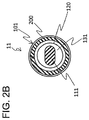
FIG. 2B is a schematic section view taken along line IIB-IIB ofFIG. 2A . -
FIG. 3 is a schematic section view illustrating a second embodiment of the invention. -
FIG. 4A is a schematic view illustrating a bent state of a guide wire, and is the schematic view illustrating the guide wire having a preferable bending displacement suppression property. -
FIG. 4B is a schematic view illustrating a bent state of a guide wire, and is the schematic view illustrating the guide wire having an inferior bending displacement suppression property. -
FIG. 5 is a graph in which the evaluation results of Table 1 are plotted. - A guide wire of the invention includes a core shaft that includes a distal end portion stepwisely reducing in diameter toward a distal end direction,
a coil body that is wound to cover at least a part of an outer periphery of the dimeter-reduced distal end portion, and
a distal end fixing portion that fixes the distal end of the core shaft, and a distal end of the coil body to each other, in which
the distal end portion of the core shaft includes a small diameter portion that is continuous with the distal end fixing portion, a large diameter portion that is positioned in a proximal end direction than the small diameter portion and has a larger outer diameter than a diameter of the small diameter portion, and a tapered portion that is continuous with the small diameter portion and the large diameter portion and gradually increases in diameter from the small diameter portion toward the large diameter portion,
the core shaft and the coil body are fixed at a portion of the core shaft excluding the tapered portion, and
bending rigidity FR1 of the large diameter portion, bending rigidity FR2 of the small diameter portion, and a length L of the tapered portion in an axial direction of the core shaft satisfy the following expressions (1) and (2):(FR1/FR2)/L≥10 ......
(1)1≤L≤3 ...... (2) (In the above expressions (1) and (2), the unit of L is mm.) - Hereinafter, the first and second embodiments of the invention is described with reference to the enclosed drawings. However, the invention is not limited to the embodiments illustrated in the drawings.
-
FIG. 1 is a schematic front view illustrating the first embodiment of the invention. Aguide wire 10 of the first embodiment roughly includes acore shaft 100, acoil body 200, and a distalend fixing part 401, as illustrated inFIG. 1 . - The
core shaft 100 has a distal end portion P1stepwisely reducing in diameter toward a distal end direction. The distal end portion P1 of thecore shaft 100 includes asmall diameter portion 110 that is continuous with the distalend fixing portion 401 described later, alarge diameter portion 120 that is positioned in a proximal end direction than thesmall diameter portion 110 and has a larger outer diameter than a diameter of thesmall diameter portion 110, and atapered portion 130 that is continuous with thesmall diameter portion 110 and thelarge diameter portion 120 and gradually increases in diameter from thesmall diameter portion 110 toward thelarge diameter portion 120. Specifically, in a state where thecore shaft 100 extends in a straight line, for example, the section shape orthogonal to the axial direction of the core shaft 100 (section shape) of each of the small-diameter portion 110 and the large-diameter portion 120 is circular with a certain diameter in the axial direction, and the section shape of thetapered portion 130 is a truncated conical shape. Further, thecore shaft 100 includes a truncatedconical connection portion 140 whose distal end is continuous with the proximal end of thelarge diameter portion 120, and a core shaftmain body 150 whose distal end is continuous to the proximal end of theconnection portion 140. - Note that the section shape of the above-described small diameter portion may be a flat shape (for example, see a
small diameter portion 111 of acore shaft 101 illustrated inFIGS. 2A and2B ). Thus, the bend of the distal end portion P11 of thecore shaft 101 can be guided in a direction perpendicular to the flat surface of the small-diameter portion 111 that is easily deformed, which makes it possible to securely control theguide wire 11 during the procedure. - The total length of the
core shaft 100 is normally 1,800 to 3,000 mm, and is preferably 1,900 to 2,500. The axial length of the distal end portion of thecore shaft 100 is normally 200 to 1,000 mm, and is preferably 300 to 850 mm. The outer diameter of the core shaftmain body 150 is usually 0.25 to 0.5 mm, and the outer diameter of thelarge diameter portion 120 is usually 1/5 to 2/5 of the core shaftmain body 150. Note that the outer diameter of thesmall diameter portion 110 is selected as described below. - Here, the outer diameters of the
large diameter portion 120 and thesmall diameter portion 110, and the length of the taperedportion 130 are selected so that the bending rigidity FR1 of the large diameter portion, the bending rigidity FR2 of the small diameter portion, and the length L of the tapered portion in the axial direction of the core shaft satisfy the following expressions (1) and (2). In the following expressions (1) and (2), the unit of L is mm.

- Here, the ratio (FR1/FR2) of the bending rigidity of the
large diameter portion 120 and thesmall diameter portion 110 in the above-described expression (1) is calculated as the ratio of the fourth power of the outer diameter using Hook's law, for example, if thecore shaft 100 is formed homogeneously. - The length of the
small diameter portion 110 in the axial direction of thecore shaft 100 is preferably not smaller than 3 mm and not larger than 15 mm. If the length of thesmall diameter portion 110 is 3 mm or larger, it is possible to allow sufficient bend of thesmall diameter portion 110, and if the length thereof is 15 mm or smaller, it is possible to prevent damages due to excessive bend of thesmall diameter portion 110. - In the embodiment, the entire length is 1,900 mm, the axial length of the distal end portion P1 is 100 mm (the axial length of the
small diameter portion 110 is 10 mm, the axial length of the taperedportion 130 is 1 mm, the axial length of thelarge diameter portion 120 is 60 mm), the outer diameter of the core shaftmain body 150 is 0.35 mm, the outer diameter of thelarge diameter portion 120 is 0.10 mm, and the outer diameter of thesmall diameter portion 110 is 0.04 mm, as an example. - The material forming the
core shaft 100 is not particularly limited as long as the flexibility of thesmall diameter portion 110 is secured and the material has antithrombogenicity and biocompatibility. For example, it is possible to adopt stainless steel such as SUS304, a superelastic alloy such as a Ni-Ti alloy, or the like. - The
coil body 200 is wound so as to cover at least a part of the outer periphery of the distal end portion P1 that is reduced in diameter. For example, thecoil body 200 is spirally formed using one single wire so that adjacent wires come into contact with each other. - Further, the
coil body 200 and the above-describedcore shaft 100 are not particularly limited as long as they are fixed at the portion of thecore shaft 100 excluding the taperedportion 130. However, from the viewpoint of improving the bendability of the distal end portion P1, it is preferable that they are fixed at the portion of thecore shaft 100 excluding thesmall diameter portion 110 and the taperedportion 130, and it is more preferable that they are fixed at the portion of thecore shaft 100 excluding thesmall diameter portion 110, thelarge diameter portion 120, and the taperedportion 130. Specifically, as illustrated inFIG. 1 , thecoil body 200 and thecore shaft 100 are brazed at two positions of between a distal end of thecoil body 200 and a distal end of the core shaft 100 (see the distal end fixing portion 401), and between a proximal end of thecoil body 200 and theconnection portion 140 of the core shaft 100 (see the brazing portion 210), for example. - Examples of the brazing material used for brazing the
coil body 200 include metal brazing such as an Sn-Pb alloy, a Pb-Ag alloy, an Sn-Ag alloy, and an Au-Sn alloy. - The diameter of the wires forming the
coil body 200 is usually 0.01 to 0.10 mm, and is preferably 0.01 to 0.08 mm. The embodiment exemplifies thecoil body 200 having a diameter of 0.06 mm. - The material forming the
coil body 200 is not particularly limited as long as the flexibility of thesmall diameter portion 110 is secured and the material has antithrombogenicity and biocompatibility. For example, it is possible to adopt stainless steel such as SUS316; a superelastic alloy such as a Ni-Ti alloy; a radiopaque metal such as platinum or tungsten, or the like. - The
distal fixing portion 401 is a portion where the distal end of thecore shaft 100 and the distal end of thecoil body 200 are fixed to each other. Specifically, as described above, the distalend fixing portion 401 is a portion where the distal end of thecore shaft 100 and the distal end of thecoil body 200 are brazed, for example, and the distal end direction thereof is formed in a smoothly bent hemispherical shape by the above-described brazing material in order to prevent damages to the inner wall of a blood vessel when theguide wire 10 advances in the blood vessel. - Next, the use mode of the
guide wire 10 will be described. First, a doctor advances the distal end of theguide wire 10 having the bent distal end portion P1 to a closed stenosis site of a leg artery or a coronary artery. Thereafter, once theguidewire 10 is inserted in the stenosis site, the distal end portion P1 of theguide wire 10 becomes, in the stenosis lesion, a J-shape starting from the bent shape and passes through the stenosis site. Theguide wire 10 passing through the stenosis site is stabilized in the J-shape (the J-shape does not progress to the U-shape) by the taperedportion 130, and passes the stenosis site in such a stabilized J-shape. After passing the stenosis site, a treatment instrument such as a balloon catheter or a stent is conveyed along theguide wire 10 to perform various treatments at the treatment site. After the treatment is completed, theguide wire 10 is withdrawn from the body by retrograding through the blood vessel, and a series of procedures is completed. - As described above, the
guide wire 10 with the above-described configuration is able to prevent breakage of thecore shaft 100 from the taperedportion 130 as a starting point while suppressing displacement of the bend of thecore shaft 100 beyond the taperedportion 130 to the proximal end direction. As a result, it is possible to perform the procedure quickly and securely by smooth operation of theguide wire 10. This is presumably the effect produced in combination of suppression of stress concentration on the taperedportion 130 during bending when thecore shaft 100 and thecoil body 200 are not fixed at the taperedportion 130 and bending controllability of the distal end portion P1 by appropriate transition in bending rigidity in the axial direction (see expressions (1) and (2)). - In this manner, the
guidewire 10 exerts the above-described effect, and thus can be preferably used as a medical guidewire used for treatment in a blood vessel, for example. -
FIG. 3 is a schematic section view illustrating the second embodiment of the invention. As illustrated inFIG. 3 , aguide wire 20 of the second embodiment roughly includes thecore shaft 100, thecoil body 200, theinner coil body 300, and a distalend fixing part 402. Theguide wire 20 is different from the first embodiment in that theinner coil body 300 and the distalend fixing portion 402 are provided. Since the configurations of thecore shaft 100, thecoil body 200, and other components are the same as those of the above-described first embodiment, the same parts are represented by the same reference numerals, and detailed description thereof will be omitted. - The
inner coil body 300 is a coil body with a multiple spiral disposed inside thecoil body 200 so as to cover thecore shaft 100, and is formed as a multiple spiral coil wound using a hollow twisted wire (a bundle of wires in which a plurality of wires are previously twisted mutually), for example, so that the adjacent wires are in contact with each other, and is arranged such that the inner periphery thereof is adjacent to the outer periphery of thelarge diameter portion 120. - In addition, the
inner coil body 300 and thecore shaft 100 are not particularly limited as long as they are fixed at a portion excluding the taperedportion 130, the portion on thecore shaft 100 in the proximal end direction than the taperedportion 130, and at the distalend fixing portion 402. However, it is preferable that they are fixed at a portion on thecore shaft 100 in the proximal end direction than thelarge diameter portion 120 and at the distalend fixing portion 402. Specifically, as illustrated inFIG. 3 , theinner coil body 300 and thecore shaft 100 are brazed at two positions of between a distal end of theinner coil body 300 and the distal ends of thecore shaft 100 and the coil body 200 (see the distal end fixing portion 402), and between the proximal end of theinner coil body 300 and theconnection part 140 of the core shaft 100 (see the brazing portion 310), for example. - Note that, as the brazing material used for brazing the
inner coil body 300, it is possible to adopt the same brazing material as the brazing material used for brazing thecoil body 200 in the first embodiment, for example. - The diameter of the wires forming the
inner coil body 300 is usually 0.01 to 0.05 mm, and is preferably 0.01 to 0.04 mm. The embodiment exemplifies theinner coil body 300 having a diameter of 0.030 mm. - As the material of the wire forming the
inner coil body 300, it is possible to adopt the same material as the material of the wire of thecoil body 200 described above in the first embodiment, for example. - The
distal fixing portion 402 is a portion where the distal end of thecore shaft 100, the distal end of thecoil body 200, and theinner coil body 300 are fixed to one another. Specifically, as described above, the distalend fixing portion 402 is a portion where the distal end of thecore shaft 100, the distal end of thecoil body 200, and the distal end of theinner coil body 300 are brazed, and the distal end side thereof is formed in a smoothly bent hemispherical shape by the brazing material, for example. - Since the use mode of the
guide wire 20 is the same as that of the first embodiment, the description of the first embodiment is cited. - In this manner, in the
guide wire 20, thecore shaft 100 and theinner coil body 300 are fixed at a portion excluding the taperedportion 130, the portion on thecore shaft 100 in the proximal end direction than the taperedportion 130, and at the distalend fixing portion 402. Therefore, even if thecore shaft 100 is broken at thesmall diameter portion 110 or the taperedportion 130, the broken portion is connected to other portions of theguide wire 20 through theinner coil body 300, which prevents split of these portions, allowing the procedure to be performed more safely. - Note that the present invention is not limited to the configurations of the above-described embodiments, but is defined by the terms of the claims and is intended to include any modifications within the scope and meaning equivalent to the terms of the claims.
- For example, the above embodiments have described the guidewires 10, 11, 20 in which the rigidity of each of the
coil body 200 and theinner coil body 300 is uniform. However, the guide wire may be formed such that the bending rigidity of the coil body and/or the inner coil body is higher in the proximal end direction than that in the distal end direction of the tapered portion in the axial direction of the core shaft. Thereby, it is possible to more largely change the rigidity of the entire guide wire at the tapered portion as a boundary, and enhance bending displacement suppression property. The coil body and the inner coil body as described above include those in which the wire diameters of the constituent wires are different before and after the tapered portion and in which the constituent wires in a portion in the proximal end direction than the tapered portion as a starting point are integrated by welding, soldering, or the like, for example. - Further, the above embodiments have described the
guide wires - The above embodiments have described the
guide wires core shaft 100 and thecoil body 200 are brazed in the first embodiment, and thecore shaft 100, thecoil body 200, and theinner coil body 300 are brazed in the second embodiment. However, the guide wire may be formed such that the above-described members are fixed by another known technique such as arc welding or resistance welding. - Further, the above embodiments have described the
guide wires core shaft 100 and thecoil body 200 are fixed at the distalend fixing portion 401 and at thebrazing portion 210 in the first embodiment, and thecore shaft 100 and theinner coil body 300 are fixed at the distalend fixing portion 402 and at thebrazing portion 310 in the second embodiment. However, the guide wire may be formed such that the above-described members are fixed at any one or two or more portions as long as such portions exclude the tapered portion. - Moreover, the above-described embodiments have described the
guide wires coil body 200 is formed as a single spiral coil and theinner coil body 300 is formed as a multiple spiral coil. However, the coil body may be formed as a multiple spiral coil, and the inner coil body may be formed as a single spiral coil. - Further, the above-described embodiments have exemplified the
guide wires connection portion 140 between thelarge diameter portion 120 and the core shaftmain body 150 of thecore shaft - Hereinafter, the invention will be specifically described based on examples, but the invention is not limited to these examples. These examples show the results regarding guide wires including a core shaft, a coil body, and a distal end fixing portion as described above in the first embodiment.
- Regarding the specifications of each guide wire to be evaluated, Table 1 shows the outer diameter D1 of the small diameter portion, the outer diameter D2 of the large diameter portion, the length L of the tapered portion in the axial direction, and the value of (FR1/FR2)/L. Note that the above FR1 and FR2 have the same meaning as those in the above-described expression (1). Other specifications are as follows.
-
- Material : SUS304 - Axial length Entire length : 1,900 mm Distal end portion : 100 mm Small diameter portion : 10 mm Tapered potion : Shown in Table 1 Large diameter portion : 60 mm - Diameter Core shaft main body : 0.35 mm Small diameter portion Shown in Table 1 Large diameter portion Shown in Table 1 -
- Material : SUS304 - Diameter :0.16mm - Using each of the guide wires shown in Table 1, the bending displacement suppression property was evaluated by the following method. The results are shown in Table 1 and
FIG. 5 . In Table 1, the bending rigidity ratio (FR1/FR2) is calculated using bending rigidity obtained by Hooke's law. - There were preliminarily prepared a guide wire having a portion in the distal end direction bent in a U-shape at a
portion 1 mm from the distal end of the small diameter portion of the core shaft as a starting point (bent section), and a transparent acrylic pipe filled with gel having hardness of 3,000 to 4,000 gf/cm2, as a simulated lesion. - Next, using the guide wire and the acrylic pipe, each guide wire was slowly inserted into the acrylic pipe so that the guide wire was not deformed, and temporarily stopped at the initial position.
- Next, the guide wire was pushed from the initial position at a speed of 1 cm/sec, and the displacement of the bent section was visually observed at the push-in position after pushing 10 cm from the initial position.
- Here, if it is not visually recognized that the bent section is displaced toward the proximal end direction of the guide wire (see
FIG. 4A , for example), the bending displacement suppression property is preferable "A", while if the displacement is visible (for example, seeFIG. 4B , for example), the bending displacement suppression property was evaluated as inferior "B". -
[Table 1] Outer diameter D1 of small diameter portion [mm] Outer diameter D2 of large diameter portion [mm] Length L of tapered portion [mm] (FR1/FR2)/L [1/mm] Bending displacement suppression property Example 1 0.040 0.074 1.0 11.5 A Example 2 0.043 0.083 1.1 12.8 A Example 3 0.043 0.084 1.0 15.2 A Example 4 0.040 0.082 1.0 17.3 A Example 5 0.043 0.090 1.1 17.3 A Example 6 0.040 0.091 1.4 19.5 A Example 7 0.043 0.090 1.4 14.1 A Example 8 0.043 0.098 1.0 26.3 A Example 9 0.043 0.097 1.1 24.5 A Example 10 0.043 0.097 1.1 24.5 A Example 11 0.043 0.100 2.8 10.6 A Example 12 0.043 0.118 1.0 55.3 A Example 13 0.043 0.119 1.1 52.3 A Example 14 0.043 0.119 1.0 59.1 A Example 15 0.043 0.130 1.2 70.6 A Example 16 0.043 0.137 1.0 100.6 A Example 17 0.041 0.137 1.1 114.0 A Example 18 0.051 0.108 1.1 17.5 A Example 19 0.051 0.109 1.2 17.3 A Example 20 0.051 0.110 1.1 19.9 A Example 21 0.054 0.117 1.1 20.8 A Example 22 0.054 0.117 1.0 22.2 A Example 23 0.054 0.118 1.1 21.0 A Example 24 0.060 0.129 1.1 19.7 A Example 25 0.060 0.128 1.0 20.2 A Example 26 0.060 0.130 1.0 21.6 A Example 27 0.031 0.085 1.5 38.0 A Example 28 0.034 0.085 1.0 40.8 A Example 29 0.034 0.085 1.6 24.7 A Example 30 0.029 0.093 1.4 76.1 A Example 31 0.033 0.093 1.0 61.8 A Example 32 0.031 0.093 1.2 70.4 A Example 33 0.037 0.093 1.0 39.1 A Example 34 0.038 0.093 1.5 24.4 A Example 35 0.039 0.093 1.2 27.0 A Comparative Example 1 0.043 0.054 1.8 1.4 B Comparative Example 2 0.040 0.054 0.7 4.5 B Comparative Example 3 0.040 0.053 1.1 2.8 B Comparative Example 4 0.043 0.056 1.2 2.4 B Comparative Example 5 0.043 0.059 1.1 3.2 B Comparative Example 6 0.043 0.058 1.3 2.5 B Comparative Example 7 0.041 0.060 0.9 5.0 B Comparative Example 8 0.042 0.062 1.2 4.1 B Comparative Example 9 0.043 0.059 1.0 3.5 B Comparative Example 10 0.040 0.064 1.0 6.8 B Comparative Example 11 0.040 0.065 1.1 6.6 B Comparative Example 12 0.043 0.068 1.1 5.4 B Comparative Example 13 0.043 0.074 1.0 9.2 B Comparative Example 14 0.045 0.075 1.2 6.6 B - As can be seen from the results in Table 1 and
FIG. 5 , the bending displacement suppression property was preferable "A" in all examples. However, it was inferior "B" in all comparative examples. -
- 10, 11, 20
- guide wire
- 100, 101
- core shaft
- 110, 111
- small diameter portion
- 120
- large diameter portion
- 130, 131
- tapered portion
- 200
- coil body
- 300
- inner coil body
- 401, 402
- distal end fixing portion
- P1, P11, P2
- distal end portion
Claims (4)
- A guide wire, comprising: a core shaft that includes a distal end portion stepwisely reducing in diameter toward a distal end direction;a coil body that is wound to cover at least a part of an outer periphery of the diameter-reduced distal end portion; anda distal end fixing portion that fixes the distal end of the core shaft, and a distal end of the coil body to each other, whereinthe distal end portion of the core shaft includes:a small diameter portion that is continuous with the distal end fixing portion,a large diameter portion that is positioned in a proximal end direction than the small diameter portion and has a larger outer diameter than a diameter of the small diameter portion, anda tapered portion that is continuous with the small diameter portion and the large diameter portion and gradually increases in diameter from the small diameter portion toward the large diameter portion,the core shaft and the coil body are fixed at a portion of the core shaft excluding the tapered portion, andbending rigidity FR1 of the large diameter portion, bending rigidity FR2 of the small diameter portion, and a length L of the tapered portion in an axial direction of the core shaft satisfy the following expressions (1) and (2):


- The guide wire according to claim 1, wherein a length of the small diameter portion in the axial direction of the core shaft is not smaller than 3 mm and not larger than 15 mm.
- The guide wire according to claim 1 or claim 2, wherein a section shape of the small diameter portion orthogonal to an axial direction of the core shaft is a flat shape.
- The guide wire according to any one of claims 1 to 3, further comprising a inner coil body that is configured as a multiple spiral coil, and is disposed inside the coil body so as to cover the core shaft, wherein
the core shaft and the inner coil body are fixed at a portion excluding the tapered portion, the portion being on the core shaft in a proximal end direction than the tapered portion, and at the distal end fixing portion.
Applications Claiming Priority (1)
| Application Number | Priority Date | Filing Date | Title |
|---|---|---|---|
| PCT/JP2017/037002 WO2019073571A1 (en) | 2017-10-12 | 2017-10-12 | Guide wire |
Publications (4)
| Publication Number | Publication Date |
|---|---|
| EP3695874A1 true EP3695874A1 (en) | 2020-08-19 |
| EP3695874A4 EP3695874A4 (en) | 2021-06-23 |
| EP3695874B1 EP3695874B1 (en) | 2024-03-06 |
| EP3695874B8 EP3695874B8 (en) | 2024-04-10 |
Family
ID=66100499
Family Applications (1)
| Application Number | Title | Priority Date | Filing Date |
|---|---|---|---|
| EP17928500.2A Active EP3695874B8 (en) | 2017-10-12 | 2017-10-12 | Guide wire |
Country Status (6)
| Country | Link |
|---|---|
| US (2) | US11541210B2 (en) |
| EP (1) | EP3695874B8 (en) |
| JP (2) | JP6929956B2 (en) |
| KR (1) | KR102427995B1 (en) |
| CN (2) | CN114668954B (en) |
| WO (1) | WO2019073571A1 (en) |
Families Citing this family (4)
| Publication number | Priority date | Publication date | Assignee | Title |
|---|---|---|---|---|
| WO2021051060A1 (en) * | 2019-09-13 | 2021-03-18 | Entellus Medical, Inc. | Image guided surgery system guide wire and methods of manufacture and use |
| US12005205B2 (en) * | 2019-12-16 | 2024-06-11 | Stryker Corporation | Guidewires for medical devices |
| CN118973650A (en) * | 2022-04-15 | 2024-11-15 | 朝日英达科株式会社 | Guidewire |
| CN115253031B (en) * | 2022-07-12 | 2025-12-09 | 青岛博泰医疗器械有限责任公司 | Single-cavity tract balloon catheter |
Family Cites Families (25)
| Publication number | Priority date | Publication date | Assignee | Title |
|---|---|---|---|---|
| JP3080483B2 (en) * | 1992-08-07 | 2000-08-28 | 朝日インテック株式会社 | Method of manufacturing medical guidewire and coil thereof |
| JPH0780076A (en) * | 1993-06-30 | 1995-03-28 | Asahi Intec Kk | Medical guidewire |
| US7455646B2 (en) | 1997-06-04 | 2008-11-25 | Advanced Cardiovascular Systems, Inc. | Polymer coated guide wire |
| JP2002531234A (en) * | 1998-12-10 | 2002-09-24 | マイクロ・セラピューティクス・インコーポレーテッド | Improved guidewire |
| US6918882B2 (en) | 2001-10-05 | 2005-07-19 | Scimed Life Systems, Inc. | Guidewire with stiffness blending connection |
| US6612998B2 (en) | 2001-11-28 | 2003-09-02 | Advanced Cardiovascular Systems, Inc. | Guide wire with marker sleeve |
| US7162715B1 (en) | 2002-03-16 | 2007-01-09 | I-Squared, Inc. | Method and apparatus for preemptive monitoring of software binaries by instruction interception and dynamic recompilation |
| US7153277B2 (en) | 2002-12-03 | 2006-12-26 | Scimed Life Systems, Inc. | Composite medical device with markers |
| US8167821B2 (en) | 2003-02-26 | 2012-05-01 | Boston Scientific Scimed, Inc. | Multiple diameter guidewire |
| US7785273B2 (en) | 2003-09-22 | 2010-08-31 | Boston Scientific Scimed, Inc. | Guidewire with reinforcing member |
| GB2410901B (en) * | 2004-02-11 | 2008-09-24 | Mediplus Ltd | Catheter guide wire |
| JP4829684B2 (en) | 2006-06-02 | 2011-12-07 | 株式会社エフエムディ | Medical guidewire |
| US20080262474A1 (en) | 2007-04-20 | 2008-10-23 | Boston Scientific Scimed, Inc. | Medical device |
| US8182432B2 (en) | 2008-03-10 | 2012-05-22 | Acclarent, Inc. | Corewire design and construction for medical devices |
| CN101502693A (en) * | 2009-03-27 | 2009-08-12 | 北京天地和协科技有限公司 | Guiding wire |
| JP4889062B2 (en) * | 2010-02-19 | 2012-02-29 | 朝日インテック株式会社 | Guide wire |
| JP5481359B2 (en) * | 2010-11-30 | 2014-04-23 | 朝日インテック株式会社 | Medical guidewire |
| JP2012200290A (en) * | 2011-03-23 | 2012-10-22 | Asahi Intecc Co Ltd | Guidewire |
| JP2013162920A (en) * | 2012-02-13 | 2013-08-22 | Asahi Intecc Co Ltd | Guide wire |
| JP2014100300A (en) * | 2012-11-20 | 2014-06-05 | Asahi Intecc Co Ltd | Guide wire |
| WO2015080948A1 (en) * | 2013-11-26 | 2015-06-04 | Boston Scientific Scimed, Inc. | Medical devices for accessing body lumens |
| JP5948535B1 (en) * | 2015-05-29 | 2016-07-06 | 株式会社エフエムディ | Medical guidewire |
| JP2016221246A (en) * | 2016-02-24 | 2016-12-28 | 株式会社エフエムディ | Medical guide wire |
| JP6159923B1 (en) * | 2016-04-28 | 2017-07-12 | 株式会社エフエムディ | Medical guidewire |
| WO2019073570A1 (en) * | 2017-10-12 | 2019-04-18 | 朝日インテック株式会社 | Guide wire |
-
2017
- 2017-10-12 CN CN202210301402.XA patent/CN114668954B/en active Active
- 2017-10-12 WO PCT/JP2017/037002 patent/WO2019073571A1/en not_active Ceased
- 2017-10-12 EP EP17928500.2A patent/EP3695874B8/en active Active
- 2017-10-12 KR KR1020207010856A patent/KR102427995B1/en active Active
- 2017-10-12 JP JP2019547858A patent/JP6929956B2/en active Active
- 2017-10-12 CN CN201780095916.1A patent/CN111225708B/en active Active
-
2020
- 2020-04-13 US US16/846,446 patent/US11541210B2/en active Active
-
2021
- 2021-08-11 JP JP2021131464A patent/JP7094426B2/en active Active
-
2022
- 2022-11-02 US US17/979,006 patent/US11701497B2/en active Active
Also Published As
| Publication number | Publication date |
|---|---|
| US20230090889A1 (en) | 2023-03-23 |
| CN111225708A (en) | 2020-06-02 |
| US11541210B2 (en) | 2023-01-03 |
| KR102427995B1 (en) | 2022-08-03 |
| KR20200054275A (en) | 2020-05-19 |
| EP3695874A4 (en) | 2021-06-23 |
| CN111225708B (en) | 2022-04-12 |
| EP3695874B8 (en) | 2024-04-10 |
| EP3695874B1 (en) | 2024-03-06 |
| JP6929956B2 (en) | 2021-09-01 |
| JP7094426B2 (en) | 2022-07-01 |
| CN114668954A (en) | 2022-06-28 |
| JP2021175551A (en) | 2021-11-04 |
| WO2019073571A1 (en) | 2019-04-18 |
| US11701497B2 (en) | 2023-07-18 |
| CN114668954B (en) | 2024-01-05 |
| US20200238054A1 (en) | 2020-07-30 |
| JPWO2019073571A1 (en) | 2020-10-22 |
Similar Documents
| Publication | Publication Date | Title |
|---|---|---|
| US11701497B2 (en) | Guide wire | |
| JP7190009B2 (en) | guide wire | |
| EP2332608A2 (en) | Guidewire | |
| US11420028B2 (en) | Guide wire | |
| US12151069B2 (en) | Guide wire | |
| JP7532573B2 (en) | Guidewires | |
| EP3006075B1 (en) | Guidewire |
Legal Events
| Date | Code | Title | Description |
|---|---|---|---|
| STAA | Information on the status of an ep patent application or granted ep patent |
Free format text: STATUS: THE INTERNATIONAL PUBLICATION HAS BEEN MADE |
|
| PUAI | Public reference made under article 153(3) epc to a published international application that has entered the european phase |
Free format text: ORIGINAL CODE: 0009012 |
|
| STAA | Information on the status of an ep patent application or granted ep patent |
Free format text: STATUS: REQUEST FOR EXAMINATION WAS MADE |
|
| 17P | Request for examination filed |
Effective date: 20200331 |
|
| AK | Designated contracting states |
Kind code of ref document: A1 Designated state(s): AL AT BE BG CH CY CZ DE DK EE ES FI FR GB GR HR HU IE IS IT LI LT LU LV MC MK MT NL NO PL PT RO RS SE SI SK SM TR |
|
| AX | Request for extension of the european patent |
Extension state: BA ME |
|
| DAV | Request for validation of the european patent (deleted) | ||
| DAX | Request for extension of the european patent (deleted) | ||
| A4 | Supplementary search report drawn up and despatched |
Effective date: 20210521 |
|
| RIC1 | Information provided on ipc code assigned before grant |
Ipc: A61M 25/09 20060101AFI20210518BHEP |
|
| GRAP | Despatch of communication of intention to grant a patent |
Free format text: ORIGINAL CODE: EPIDOSNIGR1 |
|
| STAA | Information on the status of an ep patent application or granted ep patent |
Free format text: STATUS: GRANT OF PATENT IS INTENDED |
|
| INTG | Intention to grant announced |
Effective date: 20230927 |
|
| GRAS | Grant fee paid |
Free format text: ORIGINAL CODE: EPIDOSNIGR3 |
|
| GRAA | (expected) grant |
Free format text: ORIGINAL CODE: 0009210 |
|
| STAA | Information on the status of an ep patent application or granted ep patent |
Free format text: STATUS: THE PATENT HAS BEEN GRANTED |
|
| GRAT | Correction requested after decision to grant or after decision to maintain patent in amended form |
Free format text: ORIGINAL CODE: EPIDOSNCDEC |
|
| AK | Designated contracting states |
Kind code of ref document: B1 Designated state(s): AL AT BE BG CH CY CZ DE DK EE ES FI FR GB GR HR HU IE IS IT LI LT LU LV MC MK MT NL NO PL PT RO RS SE SI SK SM TR |
|
| REG | Reference to a national code |
Ref country code: GB Ref legal event code: FG4D |
|
| REG | Reference to a national code |
Ref country code: CH Ref legal event code: PK Free format text: BERICHTIGUNG B8 Ref country code: CH Ref legal event code: EP |
|
| RAP4 | Party data changed (patent owner data changed or rights of a patent transferred) |
Owner name: ASAHI INTECC CO., LTD. |
|
| REG | Reference to a national code |
Ref country code: DE Ref legal event code: R096 Ref document number: 602017079890 Country of ref document: DE |
|
| REG | Reference to a national code |
Ref country code: IE Ref legal event code: FG4D |
|
| REG | Reference to a national code |
Ref country code: LT Ref legal event code: MG9D |
|
| PG25 | Lapsed in a contracting state [announced via postgrant information from national office to epo] |
Ref country code: LT Free format text: LAPSE BECAUSE OF FAILURE TO SUBMIT A TRANSLATION OF THE DESCRIPTION OR TO PAY THE FEE WITHIN THE PRESCRIBED TIME-LIMIT Effective date: 20240306 |
|
| REG | Reference to a national code |
Ref country code: NL Ref legal event code: MP Effective date: 20240306 |
|
| PG25 | Lapsed in a contracting state [announced via postgrant information from national office to epo] |
Ref country code: GR Free format text: LAPSE BECAUSE OF FAILURE TO SUBMIT A TRANSLATION OF THE DESCRIPTION OR TO PAY THE FEE WITHIN THE PRESCRIBED TIME-LIMIT Effective date: 20240607 |
|
| PG25 | Lapsed in a contracting state [announced via postgrant information from national office to epo] |
Ref country code: RS Free format text: LAPSE BECAUSE OF FAILURE TO SUBMIT A TRANSLATION OF THE DESCRIPTION OR TO PAY THE FEE WITHIN THE PRESCRIBED TIME-LIMIT Effective date: 20240606 Ref country code: HR Free format text: LAPSE BECAUSE OF FAILURE TO SUBMIT A TRANSLATION OF THE DESCRIPTION OR TO PAY THE FEE WITHIN THE PRESCRIBED TIME-LIMIT Effective date: 20240306 |
|
| PG25 | Lapsed in a contracting state [announced via postgrant information from national office to epo] |
Ref country code: ES Free format text: LAPSE BECAUSE OF FAILURE TO SUBMIT A TRANSLATION OF THE DESCRIPTION OR TO PAY THE FEE WITHIN THE PRESCRIBED TIME-LIMIT Effective date: 20240306 |
|
| PG25 | Lapsed in a contracting state [announced via postgrant information from national office to epo] |
Ref country code: RS Free format text: LAPSE BECAUSE OF FAILURE TO SUBMIT A TRANSLATION OF THE DESCRIPTION OR TO PAY THE FEE WITHIN THE PRESCRIBED TIME-LIMIT Effective date: 20240606 Ref country code: NO Free format text: LAPSE BECAUSE OF FAILURE TO SUBMIT A TRANSLATION OF THE DESCRIPTION OR TO PAY THE FEE WITHIN THE PRESCRIBED TIME-LIMIT Effective date: 20240606 Ref country code: LT Free format text: LAPSE BECAUSE OF FAILURE TO SUBMIT A TRANSLATION OF THE DESCRIPTION OR TO PAY THE FEE WITHIN THE PRESCRIBED TIME-LIMIT Effective date: 20240306 Ref country code: HR Free format text: LAPSE BECAUSE OF FAILURE TO SUBMIT A TRANSLATION OF THE DESCRIPTION OR TO PAY THE FEE WITHIN THE PRESCRIBED TIME-LIMIT Effective date: 20240306 Ref country code: GR Free format text: LAPSE BECAUSE OF FAILURE TO SUBMIT A TRANSLATION OF THE DESCRIPTION OR TO PAY THE FEE WITHIN THE PRESCRIBED TIME-LIMIT Effective date: 20240607 Ref country code: FI Free format text: LAPSE BECAUSE OF FAILURE TO SUBMIT A TRANSLATION OF THE DESCRIPTION OR TO PAY THE FEE WITHIN THE PRESCRIBED TIME-LIMIT Effective date: 20240306 Ref country code: ES Free format text: LAPSE BECAUSE OF FAILURE TO SUBMIT A TRANSLATION OF THE DESCRIPTION OR TO PAY THE FEE WITHIN THE PRESCRIBED TIME-LIMIT Effective date: 20240306 Ref country code: BG Free format text: LAPSE BECAUSE OF FAILURE TO SUBMIT A TRANSLATION OF THE DESCRIPTION OR TO PAY THE FEE WITHIN THE PRESCRIBED TIME-LIMIT Effective date: 20240306 |
|
| REG | Reference to a national code |
Ref country code: AT Ref legal event code: MK05 Ref document number: 1662886 Country of ref document: AT Kind code of ref document: T Effective date: 20240306 |
|
| PG25 | Lapsed in a contracting state [announced via postgrant information from national office to epo] |
Ref country code: SE Free format text: LAPSE BECAUSE OF FAILURE TO SUBMIT A TRANSLATION OF THE DESCRIPTION OR TO PAY THE FEE WITHIN THE PRESCRIBED TIME-LIMIT Effective date: 20240306 Ref country code: LV Free format text: LAPSE BECAUSE OF FAILURE TO SUBMIT A TRANSLATION OF THE DESCRIPTION OR TO PAY THE FEE WITHIN THE PRESCRIBED TIME-LIMIT Effective date: 20240306 |
|
| PG25 | Lapsed in a contracting state [announced via postgrant information from national office to epo] |
Ref country code: NL Free format text: LAPSE BECAUSE OF FAILURE TO SUBMIT A TRANSLATION OF THE DESCRIPTION OR TO PAY THE FEE WITHIN THE PRESCRIBED TIME-LIMIT Effective date: 20240306 |
|
| PG25 | Lapsed in a contracting state [announced via postgrant information from national office to epo] |
Ref country code: NL Free format text: LAPSE BECAUSE OF FAILURE TO SUBMIT A TRANSLATION OF THE DESCRIPTION OR TO PAY THE FEE WITHIN THE PRESCRIBED TIME-LIMIT Effective date: 20240306 |
|
| PG25 | Lapsed in a contracting state [announced via postgrant information from national office to epo] |
Ref country code: IS Free format text: LAPSE BECAUSE OF FAILURE TO SUBMIT A TRANSLATION OF THE DESCRIPTION OR TO PAY THE FEE WITHIN THE PRESCRIBED TIME-LIMIT Effective date: 20240706 |
|
| PG25 | Lapsed in a contracting state [announced via postgrant information from national office to epo] |
Ref country code: SM Free format text: LAPSE BECAUSE OF FAILURE TO SUBMIT A TRANSLATION OF THE DESCRIPTION OR TO PAY THE FEE WITHIN THE PRESCRIBED TIME-LIMIT Effective date: 20240306 Ref country code: PT Free format text: LAPSE BECAUSE OF FAILURE TO SUBMIT A TRANSLATION OF THE DESCRIPTION OR TO PAY THE FEE WITHIN THE PRESCRIBED TIME-LIMIT Effective date: 20240708 |
|
| PG25 | Lapsed in a contracting state [announced via postgrant information from national office to epo] |
Ref country code: EE Free format text: LAPSE BECAUSE OF FAILURE TO SUBMIT A TRANSLATION OF THE DESCRIPTION OR TO PAY THE FEE WITHIN THE PRESCRIBED TIME-LIMIT Effective date: 20240306 Ref country code: CZ Free format text: LAPSE BECAUSE OF FAILURE TO SUBMIT A TRANSLATION OF THE DESCRIPTION OR TO PAY THE FEE WITHIN THE PRESCRIBED TIME-LIMIT Effective date: 20240306 |
|
| PG25 | Lapsed in a contracting state [announced via postgrant information from national office to epo] |
Ref country code: AT Free format text: LAPSE BECAUSE OF FAILURE TO SUBMIT A TRANSLATION OF THE DESCRIPTION OR TO PAY THE FEE WITHIN THE PRESCRIBED TIME-LIMIT Effective date: 20240306 |
|
| PG25 | Lapsed in a contracting state [announced via postgrant information from national office to epo] |
Ref country code: PL Free format text: LAPSE BECAUSE OF FAILURE TO SUBMIT A TRANSLATION OF THE DESCRIPTION OR TO PAY THE FEE WITHIN THE PRESCRIBED TIME-LIMIT Effective date: 20240306 |
|
| PG25 | Lapsed in a contracting state [announced via postgrant information from national office to epo] |
Ref country code: SK Free format text: LAPSE BECAUSE OF FAILURE TO SUBMIT A TRANSLATION OF THE DESCRIPTION OR TO PAY THE FEE WITHIN THE PRESCRIBED TIME-LIMIT Effective date: 20240306 |
|
| PG25 | Lapsed in a contracting state [announced via postgrant information from national office to epo] |
Ref country code: SM Free format text: LAPSE BECAUSE OF FAILURE TO SUBMIT A TRANSLATION OF THE DESCRIPTION OR TO PAY THE FEE WITHIN THE PRESCRIBED TIME-LIMIT Effective date: 20240306 Ref country code: SK Free format text: LAPSE BECAUSE OF FAILURE TO SUBMIT A TRANSLATION OF THE DESCRIPTION OR TO PAY THE FEE WITHIN THE PRESCRIBED TIME-LIMIT Effective date: 20240306 Ref country code: RO Free format text: LAPSE BECAUSE OF FAILURE TO SUBMIT A TRANSLATION OF THE DESCRIPTION OR TO PAY THE FEE WITHIN THE PRESCRIBED TIME-LIMIT Effective date: 20240306 Ref country code: PT Free format text: LAPSE BECAUSE OF FAILURE TO SUBMIT A TRANSLATION OF THE DESCRIPTION OR TO PAY THE FEE WITHIN THE PRESCRIBED TIME-LIMIT Effective date: 20240708 Ref country code: PL Free format text: LAPSE BECAUSE OF FAILURE TO SUBMIT A TRANSLATION OF THE DESCRIPTION OR TO PAY THE FEE WITHIN THE PRESCRIBED TIME-LIMIT Effective date: 20240306 Ref country code: IS Free format text: LAPSE BECAUSE OF FAILURE TO SUBMIT A TRANSLATION OF THE DESCRIPTION OR TO PAY THE FEE WITHIN THE PRESCRIBED TIME-LIMIT Effective date: 20240706 Ref country code: EE Free format text: LAPSE BECAUSE OF FAILURE TO SUBMIT A TRANSLATION OF THE DESCRIPTION OR TO PAY THE FEE WITHIN THE PRESCRIBED TIME-LIMIT Effective date: 20240306 Ref country code: CZ Free format text: LAPSE BECAUSE OF FAILURE TO SUBMIT A TRANSLATION OF THE DESCRIPTION OR TO PAY THE FEE WITHIN THE PRESCRIBED TIME-LIMIT Effective date: 20240306 Ref country code: AT Free format text: LAPSE BECAUSE OF FAILURE TO SUBMIT A TRANSLATION OF THE DESCRIPTION OR TO PAY THE FEE WITHIN THE PRESCRIBED TIME-LIMIT Effective date: 20240306 |
|
| PG25 | Lapsed in a contracting state [announced via postgrant information from national office to epo] |
Ref country code: IT Free format text: LAPSE BECAUSE OF FAILURE TO SUBMIT A TRANSLATION OF THE DESCRIPTION OR TO PAY THE FEE WITHIN THE PRESCRIBED TIME-LIMIT Effective date: 20240306 |
|
| REG | Reference to a national code |
Ref country code: DE Ref legal event code: R097 Ref document number: 602017079890 Country of ref document: DE |
|
| PG25 | Lapsed in a contracting state [announced via postgrant information from national office to epo] |
Ref country code: IT Free format text: LAPSE BECAUSE OF FAILURE TO SUBMIT A TRANSLATION OF THE DESCRIPTION OR TO PAY THE FEE WITHIN THE PRESCRIBED TIME-LIMIT Effective date: 20240306 |
|
| PLBE | No opposition filed within time limit |
Free format text: ORIGINAL CODE: 0009261 |
|
| STAA | Information on the status of an ep patent application or granted ep patent |
Free format text: STATUS: NO OPPOSITION FILED WITHIN TIME LIMIT |
|
| PG25 | Lapsed in a contracting state [announced via postgrant information from national office to epo] |
Ref country code: DK Free format text: LAPSE BECAUSE OF FAILURE TO SUBMIT A TRANSLATION OF THE DESCRIPTION OR TO PAY THE FEE WITHIN THE PRESCRIBED TIME-LIMIT Effective date: 20240306 |
|
| PG25 | Lapsed in a contracting state [announced via postgrant information from national office to epo] |
Ref country code: DK Free format text: LAPSE BECAUSE OF FAILURE TO SUBMIT A TRANSLATION OF THE DESCRIPTION OR TO PAY THE FEE WITHIN THE PRESCRIBED TIME-LIMIT Effective date: 20240306 |
|
| 26N | No opposition filed |
Effective date: 20241209 |
|
| PG25 | Lapsed in a contracting state [announced via postgrant information from national office to epo] |
Ref country code: SI Free format text: LAPSE BECAUSE OF FAILURE TO SUBMIT A TRANSLATION OF THE DESCRIPTION OR TO PAY THE FEE WITHIN THE PRESCRIBED TIME-LIMIT Effective date: 20240306 |
|
| REG | Reference to a national code |
Ref country code: CH Ref legal event code: PL |
|
| PG25 | Lapsed in a contracting state [announced via postgrant information from national office to epo] |
Ref country code: MC Free format text: LAPSE BECAUSE OF FAILURE TO SUBMIT A TRANSLATION OF THE DESCRIPTION OR TO PAY THE FEE WITHIN THE PRESCRIBED TIME-LIMIT Effective date: 20240306 |
|
| PG25 | Lapsed in a contracting state [announced via postgrant information from national office to epo] |
Ref country code: BE Free format text: LAPSE BECAUSE OF NON-PAYMENT OF DUE FEES Effective date: 20241031 Ref country code: LU Free format text: LAPSE BECAUSE OF NON-PAYMENT OF DUE FEES Effective date: 20241012 |
|
| PG25 | Lapsed in a contracting state [announced via postgrant information from national office to epo] |
Ref country code: CH Free format text: LAPSE BECAUSE OF NON-PAYMENT OF DUE FEES Effective date: 20241031 |
|
| REG | Reference to a national code |
Ref country code: BE Ref legal event code: MM Effective date: 20241031 |
|
| PG25 | Lapsed in a contracting state [announced via postgrant information from national office to epo] |
Ref country code: IE Free format text: LAPSE BECAUSE OF NON-PAYMENT OF DUE FEES Effective date: 20241012 |
|
| PGFP | Annual fee paid to national office [announced via postgrant information from national office to epo] |
Ref country code: DE Payment date: 20251021 Year of fee payment: 9 |
|
| PGFP | Annual fee paid to national office [announced via postgrant information from national office to epo] |
Ref country code: GB Payment date: 20251022 Year of fee payment: 9 |
|
| PGFP | Annual fee paid to national office [announced via postgrant information from national office to epo] |
Ref country code: FR Payment date: 20251030 Year of fee payment: 9 |
|
| PG25 | Lapsed in a contracting state [announced via postgrant information from national office to epo] |
Ref country code: CY Free format text: LAPSE BECAUSE OF FAILURE TO SUBMIT A TRANSLATION OF THE DESCRIPTION OR TO PAY THE FEE WITHIN THE PRESCRIBED TIME-LIMIT; INVALID AB INITIO Effective date: 20171012 |
|
| PG25 | Lapsed in a contracting state [announced via postgrant information from national office to epo] |
Ref country code: HU Free format text: LAPSE BECAUSE OF FAILURE TO SUBMIT A TRANSLATION OF THE DESCRIPTION OR TO PAY THE FEE WITHIN THE PRESCRIBED TIME-LIMIT; INVALID AB INITIO Effective date: 20171012 |