EP3695599B1 - Intra-prediction mode concept for block-wise picture coding - Google Patents
Intra-prediction mode concept for block-wise picture coding Download PDFInfo
- Publication number
- EP3695599B1 EP3695599B1 EP18789026.4A EP18789026A EP3695599B1 EP 3695599 B1 EP3695599 B1 EP 3695599B1 EP 18789026 A EP18789026 A EP 18789026A EP 3695599 B1 EP3695599 B1 EP 3695599B1
- Authority
- EP
- European Patent Office
- Prior art keywords
- intra
- prediction
- neural network
- mode
- coding
- Prior art date
- Legal status (The legal status is an assumption and is not a legal conclusion. Google has not performed a legal analysis and makes no representation as to the accuracy of the status listed.)
- Active
Links
Images






Classifications
-
- H—ELECTRICITY
- H04—ELECTRIC COMMUNICATION TECHNIQUE
- H04N—PICTORIAL COMMUNICATION, e.g. TELEVISION
- H04N19/00—Methods or arrangements for coding, decoding, compressing or decompressing digital video signals
- H04N19/10—Methods or arrangements for coding, decoding, compressing or decompressing digital video signals using adaptive coding
- H04N19/102—Methods or arrangements for coding, decoding, compressing or decompressing digital video signals using adaptive coding characterised by the element, parameter or selection affected or controlled by the adaptive coding
- H04N19/103—Selection of coding mode or of prediction mode
- H04N19/11—Selection of coding mode or of prediction mode among a plurality of spatial predictive coding modes
-
- G—PHYSICS
- G06—COMPUTING OR CALCULATING; COUNTING
- G06N—COMPUTING ARRANGEMENTS BASED ON SPECIFIC COMPUTATIONAL MODELS
- G06N3/00—Computing arrangements based on biological models
- G06N3/02—Neural networks
- G06N3/04—Architecture, e.g. interconnection topology
- G06N3/045—Combinations of networks
-
- G—PHYSICS
- G06—COMPUTING OR CALCULATING; COUNTING
- G06N—COMPUTING ARRANGEMENTS BASED ON SPECIFIC COMPUTATIONAL MODELS
- G06N3/00—Computing arrangements based on biological models
- G06N3/02—Neural networks
- G06N3/04—Architecture, e.g. interconnection topology
- G06N3/048—Activation functions
-
- G—PHYSICS
- G06—COMPUTING OR CALCULATING; COUNTING
- G06N—COMPUTING ARRANGEMENTS BASED ON SPECIFIC COMPUTATIONAL MODELS
- G06N3/00—Computing arrangements based on biological models
- G06N3/02—Neural networks
- G06N3/04—Architecture, e.g. interconnection topology
- G06N3/0499—Feedforward networks
-
- G—PHYSICS
- G06—COMPUTING OR CALCULATING; COUNTING
- G06N—COMPUTING ARRANGEMENTS BASED ON SPECIFIC COMPUTATIONAL MODELS
- G06N3/00—Computing arrangements based on biological models
- G06N3/02—Neural networks
- G06N3/08—Learning methods
-
- G—PHYSICS
- G06—COMPUTING OR CALCULATING; COUNTING
- G06N—COMPUTING ARRANGEMENTS BASED ON SPECIFIC COMPUTATIONAL MODELS
- G06N3/00—Computing arrangements based on biological models
- G06N3/02—Neural networks
- G06N3/08—Learning methods
- G06N3/09—Supervised learning
-
- G—PHYSICS
- G06—COMPUTING OR CALCULATING; COUNTING
- G06T—IMAGE DATA PROCESSING OR GENERATION, IN GENERAL
- G06T9/00—Image coding
- G06T9/002—Image coding using neural networks
-
- H—ELECTRICITY
- H04—ELECTRIC COMMUNICATION TECHNIQUE
- H04N—PICTORIAL COMMUNICATION, e.g. TELEVISION
- H04N19/00—Methods or arrangements for coding, decoding, compressing or decompressing digital video signals
- H04N19/10—Methods or arrangements for coding, decoding, compressing or decompressing digital video signals using adaptive coding
- H04N19/102—Methods or arrangements for coding, decoding, compressing or decompressing digital video signals using adaptive coding characterised by the element, parameter or selection affected or controlled by the adaptive coding
- H04N19/103—Selection of coding mode or of prediction mode
- H04N19/109—Selection of coding mode or of prediction mode among a plurality of temporal predictive coding modes
-
- H—ELECTRICITY
- H04—ELECTRIC COMMUNICATION TECHNIQUE
- H04N—PICTORIAL COMMUNICATION, e.g. TELEVISION
- H04N19/00—Methods or arrangements for coding, decoding, compressing or decompressing digital video signals
- H04N19/10—Methods or arrangements for coding, decoding, compressing or decompressing digital video signals using adaptive coding
- H04N19/169—Methods or arrangements for coding, decoding, compressing or decompressing digital video signals using adaptive coding characterised by the coding unit, i.e. the structural portion or semantic portion of the video signal being the object or the subject of the adaptive coding
- H04N19/17—Methods or arrangements for coding, decoding, compressing or decompressing digital video signals using adaptive coding characterised by the coding unit, i.e. the structural portion or semantic portion of the video signal being the object or the subject of the adaptive coding the unit being an image region, e.g. an object
- H04N19/176—Methods or arrangements for coding, decoding, compressing or decompressing digital video signals using adaptive coding characterised by the coding unit, i.e. the structural portion or semantic portion of the video signal being the object or the subject of the adaptive coding the unit being an image region, e.g. an object the region being a block, e.g. a macroblock
-
- H—ELECTRICITY
- H04—ELECTRIC COMMUNICATION TECHNIQUE
- H04N—PICTORIAL COMMUNICATION, e.g. TELEVISION
- H04N19/00—Methods or arrangements for coding, decoding, compressing or decompressing digital video signals
- H04N19/50—Methods or arrangements for coding, decoding, compressing or decompressing digital video signals using predictive coding
- H04N19/593—Methods or arrangements for coding, decoding, compressing or decompressing digital video signals using predictive coding involving spatial prediction techniques
-
- H—ELECTRICITY
- H04—ELECTRIC COMMUNICATION TECHNIQUE
- H04N—PICTORIAL COMMUNICATION, e.g. TELEVISION
- H04N19/00—Methods or arrangements for coding, decoding, compressing or decompressing digital video signals
- H04N19/60—Methods or arrangements for coding, decoding, compressing or decompressing digital video signals using transform coding
- H04N19/61—Methods or arrangements for coding, decoding, compressing or decompressing digital video signals using transform coding in combination with predictive coding
-
- H—ELECTRICITY
- H04—ELECTRIC COMMUNICATION TECHNIQUE
- H04N—PICTORIAL COMMUNICATION, e.g. TELEVISION
- H04N19/00—Methods or arrangements for coding, decoding, compressing or decompressing digital video signals
- H04N19/70—Methods or arrangements for coding, decoding, compressing or decompressing digital video signals characterised by syntax aspects related to video coding, e.g. related to compression standards
Definitions
- Encoder 14 may support different prediction modes so as to derive the prediction signal for a certain block 18.
- the prediction modes which are of importance in the following embodiments, are intra-prediction modes according to which the inner of block 18 is predicted spatially from neighboring, already encoded samples of picture 10.
- the encoding of picture 10 into datastream 12 and, accordingly, the corresponding decoding procedure may be based on a certain coding order 20 defined among blocks 18.
- the coding order 20 may traverse blocks 18 in a raster scan order such as row-wise from top to bottom with traversing each row from left to right, for instance.
- Transformed blocks may, for instance, be the result of further subdivisioning coding blocks.
- the examples set out herein should not be treated as being limiting and other examples exist as well.
- the subdivisioning into coding blocks may, for instance, use multi-tree subdivisioning, and prediction blocks and/or transform blocks may be obtained by further subdividing coding blocks using multi-tree subdivisioning, as well.
- encoder 14 chooses or selects coding decisions according to some optimization suggest, for instance, in order to minimize some cost function which may depend on coding rate and/or coding distortion.
- One of these coding options or coding parameters may involve a selection of the intra-prediction mode to be used for a current block 18 among available or supported intra-prediction modes.
- the selected intra-prediction mode may then be signaled by encoder 14 for current block 18 within datastream 12 with decoder 54 redoing the selection using this signalization in datastream 12 for block 18.
- dequantized and retransformed prediction residual signal applied to added 42' is derived by a sequence of entropy decoder 56 which inverses the entropy encoding of entropy encoder 28b, followed by the residual signal reconstruction stage 36' which is composed of dequantizer 38' and inverse transformer 40' just as it is the case on encoding side.
- the decoder's output is the reconstruction of picture 10.
- the reconstruction of picture 10 may be available directly at the output of adder 42' or, alternatively, at the output of in-loop filter 46'.
- Some post-filter may be arranged at the decoder's output in order to subject the reconstruction of picture 10 to some post-filtering in order to improve the picture quality, but this option is not depicted in Fig. 4 .
- Fig. 5 shows a current block 18, i.e. a block currently to be encoded or decoded.
- Fig. 5 shows a set 60 of neighboring samples 62, i.e. samples 62 with spatially neighbor block 18.
- the samples 64 within block 18 are to be predicted.
- the prediction signal to be derived is, thus, a prediction for each sample 64 within block 18.
- a plurality 66 of prediction modes are available for each block 18 and if block 18 is to be intra-predicted, this plurality 66 of modes merely comprises inter-prediction modes.
- FIG. 6 shows that encoder and decoder have one neural network 80 0 to 80 KB -1 for each of the neural network-based intra-prediction modes of set 72.
- Set 60 is applied to the respective neural network so as to derive the corresponding intra-prediction mode among set 72.
- Fig. 6 rather representatively shows one block 82 as providing on the basis of the input, namely the set 60 of neighboring samples, the one or more prediction signals of the one or more intra-prediction modes of set 74, e.g. the DC mode prediction signal and/or angular intra-prediction mode prediction signal.
- the specific embodiment set out hereinafter also provides encoder and decoder with another neural network 84 which is dedicated to provide a probability value for each neural network-based intra-prediction mode within set 72 on the basis of a set 86 of neighboring samples which may or may not coincide with set 60.
- the probability values thus provided when the neural network 84 assists in rendering the side information 70 for the mode selection more effective.
- the probability values provided by the neural network 84 enable to use the variable length code within the side information 70 as an index into an ordered list of intra-prediction modes ordered according to the probability values output by neural network 84 for the neural network-based intra-prediction modes within set 72, thereby optimizing or reducing the code rate for the side information 70.
- the mode selection 68 is effectively performed depending on both, the probability values provided by the further neural network 84 as well as the side information 70 within datastream 12.
- B ⁇ Z 2 be a block of a video frame, i.e. block 18.
- B has M pixels.
- R M the content of a video signal on B .
- B rec ⁇ Z 2 of B that has L pixels and on which an already reconstructed image rec ⁇ R L is available, i.e. sample sets 60 and 86 although they may alternatively differ.
- F ( rec ) a predictor for im.
- the true function D + ⁇ ⁇ R is typically very complex and is not given by a closed expression on can feed a data driven optimization algorithm with. Thus, we approximate either the whole function D + ⁇ R or at least the rate function R by a piecewise smooth function.
- the functions in (2) define the neural network 80 0 - 80 KB -1 in Fig. 6 .
- each of these functions consists of a sequence of compositions of functions which are either: 1) An affine transofrmation Aff or 2) A non-linear activation function Act.
- affine transformation Aff R m ⁇ R n
- Aff x L x + b
- Each linear map L : R m ⁇ R n is completely determined by a matrix in R n ⁇ m , i.e. corresponds uniquely to a vector ⁇ L ⁇ R m ⁇ n .
- ⁇ : R ⁇ R may alternatively be a piecewise smooth function, for example.
- T ⁇ N , L ⁇ N and M ⁇ N are as in (1).
- F ⁇ B Aff ⁇ k ⁇ ⁇ ⁇ Aff ⁇ k ⁇ 1 ⁇ ⁇ ⁇ Aff ⁇ k ⁇ 2 ⁇ ... ⁇ ⁇ ⁇ Aff ⁇ 1 .
- F ⁇ B would, thus, describe a neural network 80 i parametrized using paramters ⁇ .
- Each row of Aff ⁇ j incorpartes the weights controlling as to how strong a signal strength respectively activation of each of the m predecessor neurons is forwarded to the respective neuron of the neuron layer j which corresponds to the respective row.
- ⁇ controlls for each neuron of neuron layer j the non-linear mapping of its linear combination of forwarded predecessor neuron activations onto its own activation.
- the number of neurons per layer may vary.
- the number of nuron layers k may vary among the various neural networks 80 j , i.e. for different j. Note, that the non-linear function might vary per neurion layer or even per neuron or at some other units.
- Loss F fix B total as follows.
- BL min ⁇ BL be the set of all minimal elements in .
- index i In the code design to parse the latter index i, it is required that the number of bits needed to signal an index i 1 ⁇ ⁇ 1, ..., K B ⁇ is less or equal than the number of bits to signal an index i 2 ⁇ ⁇ 1, ..., K B ⁇ if ⁇ ( i 1 ) ⁇ ⁇ ( i 2 ) and if all involved underlying probabilities used by the entropy coding engine are set to equal probability.
- the apparatus 54 supports a plurality of intra-prediction modes comprising, at least, a set 72 of intra-prediction modes according to which the intra-prediction signal for a current block 18 of the picture 10 is determined by applying a first set 60 of neighboring samples of the current block 18 onto a neural network 80 i .
- the apparatus 54 is configured to select 68 for the current block 18 one intra-prediction mode out of the plurality 66 of intra-prediction modes and predicts 71 the current block 18 using the one intra-prediction mode, namely using the corresponding neural network 80 m having been selected.
- decoder 54 does not use, and does not comprise, the further neural network 84.
- the decoder 54 could decode from datastream 12 an index for block 18 using a variable length code, the code length of which are indicated in M B , and the decoder 54 would perform the selection 68 based on this index.
- the index would be part of the side information 70.
- the decoder 54 comprises the further neural network 84 which determines, for each intra-prediction mode of the set 72 of intra-prediction modes, a probability value by applying set 86 of neighboring samples thereonto and ordering these probability values in order to determine a rank for each intra-prediction mode of set 72, thereby obtaining an ordered list of intra-prediction modes.
- An index in the datastream 12 as part of side information 70 is then used as an index into the ordered list.
- this index may be coded using variable length code for which M B indicates the code length.
- a flag 70a within the side information 70 for block 18 indicates whether the intra-prediction mode determined to be the best mode for block 18 by the encoder in step 90, is within set 72, i.e., is neural network based intra-prediction mode, or within set 74, i.e., one of the non-neural network based intra-prediction modes.
- the encoder inserts flag 70a into data stream 12 accordingly, while the decoder retrieves it therefrom.
- Fig. 7a assumes that the determined intra-prediction mode 92 is within set 72.
- FIG. 7c show a case of not using flag 70a, but the flag could be used alternatively.
- the issue which Fig. 7c is directed pertains to the possibility that neither encoder nor decoder uses neural network 84. Rather, the ordering 96 is derived by other means such as coding parameters conveyed within data stream 12 with respect to one or more neighboring blocks 18, i.e., portions 98 of a data stream 12 which pertains to such one or more neighboring blocks.
- Fig. 8 depicted as individual units, i.e., neural network 84 0 for providing the probability value for neural network based intra-prediction mode 0 to neural network 84 KB-1 for providing the probability value associated with the neural network based intra-prediction mode K B-1 .
- the parameters 111 for parametrizing neural networks 84 and the parameters 113 for parametrizing neural networks 80 0 to 80 KB-1 are input or applied to respective parameter inputs of these neural networks by an updater 110.
- Apparatus 108 has access to a reservoir or a plurality of picture test blocks 114 along with corresponding neighboring samples sets 116. Pairs of these blocks 114 and their associated neighboring sample sets 116 are sequentially used by apparatus 108.
- a current picture test block 114 is applied to parameterizable neural network 109 so that neural networks 80 provide a prediction signal 118 for each neural network based intra-prediction mode of set 72, and each neural network 80 provides a probability value for each of these modes.
- these neural networks use their current parameters 111 and 113.
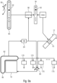
- Fig. 9b shows an alternative to Fig. 9a in that instead of the ordering, entropy de/encoding 100 of the index 70 is used with controlling the probability or simple statistics thereof, i.e. controlling the entropy probability distribution for entropy de/encoding in en/decoder, according to the probability values determined for the neural network 84 for each mode of plurality 66.
- the dependency on the probability values may not only affect the coding of the side information 70 into datastream 12 using, for instance, a respective variable length coding of an index into the ordered list or using entropy en/decoding with a probability distribution estimation depending on the neural network's probability values, but also the optimization step 90: here, the code rate for transmitting side information 70 may be taken into account and may, thus, influence the determination 90.
- the inventive encoded data stream can be stored on a digital storage medium or can be transmitted on a transmission medium such as a wireless transmission medium or a wired transmission medium such as the Internet.
- embodiments of the invention can be implemented in hardware or in software.
- the implementation can be performed using a digital storage medium, for example a floppy disk, a DVD, a Blu-Ray, a CD, a ROM, a PROM, an EPROM, an EEPROM or a FLASH memory, having electronically readable control signals stored thereon, which cooperate (or are capable of cooperating) with a programmable computer system such that the respective method is performed. Therefore, the digital storage medium may be computer readable.
- embodiments of the present invention can be implemented as a computer program product with a program code, the program code being operative for performing one of the methods when the computer program product runs on a computer.
- the program code may for example be stored on a machine readable carrier.
- inventions comprise the computer program for performing one of the methods described herein, stored on a machine readable carrier.
- a further embodiment of the inventive method is, therefore, a data stream or a sequence of signals representing the computer program for performing one of the methods described herein.
- the data stream or the sequence of signals may for example be configured to be transferred via a data communication connection, for example via the Internet.
- a programmable logic device for example a field programmable gate array
- a field programmable gate array may cooperate with a microprocessor in order to perform one of the methods described herein.
- the methods are preferably performed by any hardware apparatus.
- the apparatus described herein, or any components of the apparatus described herein, may be implemented at least partially in hardware and/or in software.
- the methods described herein may be performed using a hardware apparatus, or using a computer, or using a combination of a hardware apparatus and a computer.
Landscapes
- Engineering & Computer Science (AREA)
- Theoretical Computer Science (AREA)
- Physics & Mathematics (AREA)
- Multimedia (AREA)
- Signal Processing (AREA)
- Evolutionary Computation (AREA)
- Artificial Intelligence (AREA)
- General Physics & Mathematics (AREA)
- General Health & Medical Sciences (AREA)
- Data Mining & Analysis (AREA)
- Computational Linguistics (AREA)
- Molecular Biology (AREA)
- Computing Systems (AREA)
- General Engineering & Computer Science (AREA)
- Biophysics (AREA)
- Mathematical Physics (AREA)
- Software Systems (AREA)
- Biomedical Technology (AREA)
- Life Sciences & Earth Sciences (AREA)
- Health & Medical Sciences (AREA)
- Compression Or Coding Systems Of Tv Signals (AREA)
Description
- The present application is concerned with an improved intra-prediction mode concept for block-wise picture coding such as usable in a video codec such as HEVC or any successor of HEVC.
- Intra-prediction modes are widely used in picture and video coding. In video coding, intra-prediction modes compete with other prediction modes such as inter-prediction modes such as motion-compensated prediction modes. In intra-prediction modes, a current block is predicted on the basis of neighboring samples, i.e. samples already encoded as far as the encoder side is concerned, and already decoded as far as the decoder side is concerned. Frankly speaking, neighboring sample values are extrapolated into the current block so as to form a prediction signal for the current block with the prediction residual being transmitted in the datastream for the current block. The better the prediction signal is, the lower the prediction residual is and, accordingly, a lower number of bits is necessary to code the prediction residual.
- In order to be effective, several aspects should be taken into account in order to form an effective frame work for intra-prediction in a block-wise picture coding environment. For instance, the larger the number of intra-prediction modes supported by the codec, the larger the side information rate consumption is in order to signal the selection to the decoder. On the other hand, the set of supported intra-prediction modes should be able to provide a good prediction signal, i.e. a prediction signal resulting in a low prediction residual.
- The present application seeks to provide an intra-prediction mode concept allowing for a more efficient compression of a block-wise picture codec if using the improved intra-prediction mode concept.
- Document
EP 3 310 058 A1 may be construed to disclose an image encoding method that includes: encoding an image including a block by performing, in at least one of intra prediction, inter prediction, and an in-loop filter, a non-linear process by which the input-output relationship becomes non-linear; and encoding an operation parameter of a non-linear filter to be used in the non-linear process. -
Document EP 2 063 644 A2 may be construed to disclose a technique in which, in an image encoding/decoding device, the prediction direction in a target block, i.e., a block which becomes the target of the intraframe prediction processing, is estimated by taking advantage of pre-encoded blocks which are adjacent to the target block. First, as edge information on decoded images on the adjacent blocks, intensities and angles of the edges are calculated. Next, of the degrees of likelihood calculated with respect to each prediction direction by taking advantage of this edge information and, e.g., a neural network, the prediction direction whose degree of likelihood is the highest is employed as the prediction direction in the target block. Also, a variable-length code table is dynamically created based on the estimated result, which allows a significant reduction in the prediction-direction representing code amount. Document "Intra prediction using fully connected network for video coding", Jiahao Li et al., Transactions on the 2017 IEEE International Conference on Image Processing, may be construed to disclose a technique for applying deep neural network to improve the state-of-the-art intra prediction. Considering the characteristics of block-based video coding framework, the document proposes a fully connected network for intra prediction where all layers except non-linear ones are fully connected. In the proposed network, the inputs are multiple reference lines of the current block and the output is the prediction for the block. When compared with the traditional intra prediction method, the richer context of current block is exploited. - Document "Convolutional Neural Networks Based Intra Prediction for HEVC", Wenxue Cui et al., Transactions on the 2017 Data Compression Conference, Researchgate, may be construed to disclose an intra prediction convolutional neural network (IPCNN) for intra prediction, which exploits the rich context of the current block and therefore is capable of improving the accuracy of predicting the current block. Meanwhile, the predictions of the three nearest blocks can also be refined. CNNs are applied to intra prediction for HEVC.
- This object is achieved by the subject-matter of the independent claims of the present application. Further developments are set forth in the dependent claims.
- Basis for the claimed invention may be found in
Figure 8 and the associated description. The other Figures relate to unclaimed examples, which provide information useful for understanding the claimed invention. These are described in the following with respect to the Figures, among which: - Fig. 1
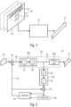
- shows a schematic block diagram illustrating an encoder for encoding a picture into a datastream as a general example where embodiments of the present application may be implemented;
- Fig. 2
- shows a block diagram of a more specific example for an encoder according to
Fig. 1 ; - Fig. 3
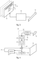
- shows a schematic block diagram illustrating a decoder fitting to the encoder of
Fig. 1 and serving as an example for a decoder where embodiments of the present application may be implemented into; - Fig. 4
- shows a block diagram of a more specific example of a decoder of
Fig. 3 , which fits to the encoder ofFig. 2 ; - Fig. 5
- shows a schematic diagram illustrating the mode of operation in encoder and decoder according to embodiments of the present application with respect to processing a block using intra-prediction;
- Fig. 6
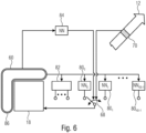
- shows a schematic block diagram illustrating a decoder in accordance with an embodiment of the present application comprising several neural network-based intra-prediction modes;
- Fig. 7a
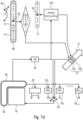
- shows a schematic diagram illustrating the mode of operation of an encoder and a decoder in accordance with an embodiment supporting neural network-based in- tra-prediction modes and a neural network-based ordering of these modes with transmitting within the datastream an index into an ordered list of neural network-based intra-prediction modes along with a fleck indicating whether the intra-prediction mode to be used is member of the set of neural network-based intra-prediction modes or not. It is needless to say the index may be coded using variable length coding so as to take advantage of the different frequency of being determined by
determination 90; - Fig. 7b
- shows a schematic diagram differing from
Fig. 7a in that the fleck signalization is not used; - Fig. 7c
- shows a schematic diagram differing from 7b in that the mode ordering is not controlled using a neural network;
- Fig. 7d
- shows a schematic diagram differing from 7a in that the neural network assistance in mode signalization is used for controlling the probability distribution estimation in entropy en/decoding rather than for mode ordering;
- Fig. 8
- shows an apparatus for designing a set of neural network-based intra-prediction modes in accordance with an embodiment;
- Fig. 9a
- shows a schematic diagram illustrating the mode of operation of encoder and decoder in accordance with an embodiment according to which a neural network is used for ordering supported intra-prediction modes irrespective of whether neural network-based or not;
- Fig. 9b
- shows a schematic diagram differing from
Fig. 9a in that the neural network base is used for controlling the probabilities distribution estimation for entropy de/encoding of the index into the set of supported intra-prediction modes; - Fig. 10
- shows an apparatus for designing a neural network for assisting and selecting among a set of intra-prediction mode for block-based picture coding in accordance with an embodiment.
- In the following, various embodiments are described which assist in achieving a more effective compression when using intra-prediction. Some embodiments achieve the compression efficiency increase by spending a set of intra-prediction modes which are neural network-based. The latter ones may be added to other intra-prediction modes heuristically designed, for instance, or may be provided exclusively. Other embodiments use a neural network in order to perform a selection among a plurality of intra-prediction modes. And even other embodiments make use of both of the just-discussed specialties.
- In order to ease the understanding of the following embodiments of the present application, the description starts with a presentation of possible encoders and decoders fitting thereto into which the subsequently outlined embodiments of the present application could be built.
Fig. 1 shows an apparatus for block-wise encoding apicture 10 into adatastream 12. The apparatus is indicated usingreference sign 14 and may be a still picture encoder or a video encoder. In other words,picture 10 may be a current picture out of avideo 16 when theencoder 14 is configured to encodevideo 16 includingpicture 10 intodatastream 12, orencoder 14 may encodepicture 10 intodatastream 12 exclusively. - As mentioned,
encoder 14 performs the encoding in a block-wise manner or block-base. To this,encoder 14 subdividespicture 10 into blocks a team in units of which encoder 14 encodespicture 10 intodatastream 12. Examples of possible subdivisions ofpicture 10 intoblocks 18 are set out in more detail below. Generally, the subdivision may end-up intoblocks 18 of constant size suggest an array of blocks arranged in rows and columns or intoblocks 18 of different block sizes such as by use of a hierarchical multi-tree subdivisioning with starting the multi-tree subdivisioning from the whole picture area ofpicture 10 or from a pre-partitioning ofpicture 10 into an array of tree blocks wherein these examples shall not be treated as excluding other possible ways ofsubdivisioning picture 10 intoblocks 18. - Further,
encoder 14 is a predictive encoder configured to predictively encodepicture 10 intodatastream 12. For acertain block 18 this means thatencoder 14 determines a prediction signal forblock 18 and encodes the prediction residual, i.e. the prediction error at which the prediction signal deviates from the actual picture content withinblock 18, intodatastream 12. -
Encoder 14 may support different prediction modes so as to derive the prediction signal for acertain block 18. The prediction modes, which are of importance in the following embodiments, are intra-prediction modes according to which the inner ofblock 18 is predicted spatially from neighboring, already encoded samples ofpicture 10. The encoding ofpicture 10 intodatastream 12 and, accordingly, the corresponding decoding procedure, may be based on acertain coding order 20 defined among blocks 18. For instance, thecoding order 20 may traverseblocks 18 in a raster scan order such as row-wise from top to bottom with traversing each row from left to right, for instance. In case of hierarchical multi-tree based subdivisioning, raster scan ordering may be applied within each hierarchy level, wherein a depth-first traversal order may be applied, i.e. leaf notes within a block of a certain hierarchy level may precede blocks of the same hierarchy level having the same parent block according tocoding order 20. Depending on thecoding order 20, neighboring, already encoded samples of ablock 18 may be located usually at one or more sides ofblock 18. In case of the examples presented herein, for instance, neighboring, already encoded samples of ablock 18 are located to the top of, and to the left ofblock 18. - Intra-prediction modes may not be the only ones supported by
encoder 14. In case ofencoder 14 being a video encoder, for instance,encoder 14 may also support intra-prediction modes according to which ablock 18 is temporarily predicted from a previously encoded picture ofvideo 16. Such an intra-prediction mode may be a motion-compensated prediction mode according to which a motion vector is signaled for such ablock 18 indicating a relative spatial offset of the portion from which the prediction signal ofblock 18 is to be derived as a copy. Additionally or alternatively, other non-intra-prediction modes may be available as well such as inter-view prediction modes in case ofencoder 14 being a multi-view encoder, or non-predictive modes according to which the inner ofblock 18 is coded as is, i.e. without any prediction. - Before starting with focusing the description of the present application onto intra-prediction modes, a more specific embodiment for a possible block-based encoder, i.e. for a possible implementation of
encoder 14, as described with respect toFig. 2 with then presenting two corresponding embodiments for a decoder fitting toFigs. 1 and 2 , respectively. -
Fig. 2 shows a possible implementation ofencoder 14 ofFig. 1 , namely one where the encoder is configured to use transform coding for encoding the prediction residual although this is nearly an example and the present application is not restricted to that sort of prediction residual coding. According toFig. 2 ,encoder 14 comprises asubtractor 22 configured to subtract from the inbound signal, i.e.picture 10 or, on a block basis,current block 18, thecorresponding prediction signal 24 so as to obtain the predictionresidual signal 26 which is then encoded by a predictionresidual encoder 28 into adatastream 12. The predictionresidual encoder 28 is composed of alossy encoding stage 28a and alossless encoding stage 28b. Thelossy stage 28a receives the predictionresidual signal 26 and comprises aquantizer 30 which quantizes the samples of the predictionresidual signal 26. As already mentioned above, the present example uses transform coding of the predictionresidual signal 26 and accordingly, thelossy encoding stage 28a comprises atransform stage 32 connected betweensubtractor 22 andquantizer 30 so as to transform such a spectrally decomposed prediction residual 26 with a quantization ofquantizer 30 taking place on the transformed coefficients where presenting theresidual signal 26. The transform may be a DCT, DST, FFT, Hadamard transform or the like. The transformed and quantized predictionresidual signal 34 is then subject to lossless coding by thelossless encoding stage 28b which is an entropy coder entropy coding quantized predictionresidual signal 34 intodatastream 12.Encoder 14 further comprises the prediction residualsignal reconstruction stage 36 connected to the output ofquantizer 30 so as to reconstruct from the transformed and quantized predictionresidual signal 34 the prediction residual signal in a manner also available at the decoder, i.e. taking the coding loss isquantizer 30 into account. To this end, the predictionresidual reconstruction stage 36 comprises adequantizer 38 which perform the inverse of the quantization ofquantizer 30, followed by aninverse transformer 40 which performs the inverse transformation relative to the transformation performed bytransformer 32 such as the inverse of the spectral decomposition such as the inverse to any of the above-mentioned specific transformation examples.encoder 14 comprises anadder 42 which adds the reconstructed prediction residual signal as output byinverse transformer 40 and theprediction signal 24 so as to output a reconstructed signal, i.e. reconstruct examples. This output is fed into apredictor 44 ofencoder 14 which then determines theprediction signal 24 based thereon. It ispredictor 44 which supports all the prediction modes already discussed above with respect toFig. 1. Fig. 2 also illustrates that in case ofencoder 14 being a video encoder,encoder 14 may also comprise an in-loop filter 46 with filters completely reconstructed pictures which, after having been filtered, form reference pictures forpredictor 44 with respect to inter-predicted block. - As already mentioned above,
encoder 14 operates block-based. For the subsequent description, the block bases of interest is the one subdividingpicture 10 into blocks for which the intra-prediction mode is selected out of a set or plurality of intra-prediction modes supported bypredictor 44 orencoder 14, respectively, and the selected intra-prediction mode performed individually. Other sorts of blocks into whichpicture 10 is subdivided may, however, exist as well. For instance, the above-mentioned decision whetherpicture 10 is inter-coded or intra-coded may be done at a granularity or in units of blocks deviating from blocks 18. For instance, the inter/intra mode decision may be performed at a level of coding blocks into whichpicture 10 is subdivided, and each coding block is subdivided into prediction blocks. Prediction blocks with encoding blocks for which it has been decided that intra-prediction is used, are each subdivided to an intra-prediction mode decision. To this, for each of these prediction blocks, it is decided as to which supported intra-prediction mode should be used for the respective prediction block. These prediction blocks will formblocks 18 which are of interest here. Prediction blocks within coding blocks associated with inter-prediction would be treated differently bypredictor 44. They would be inter-predicted from reference pictures by determining a motion vector and copying the prediction signal for this block from a location in the reference picture pointed to by the motion vector. Another block subdivisioning pertains the subdivisioning into transform blocks at units of which the transformations bytransformer 32 andinverse transformer 40 are performed. Transformed blocks may, for instance, be the result of further subdivisioning coding blocks. Naturally, the examples set out herein should not be treated as being limiting and other examples exist as well. For the sake of completeness only, it is noted that the subdivisioning into coding blocks may, for instance, use multi-tree subdivisioning, and prediction blocks and/or transform blocks may be obtained by further subdividing coding blocks using multi-tree subdivisioning, as well. - A decoder or apparatus for block-wise decoding fitting to the
encoder 14 ofFig. 1 is depicted inFig. 3 . Thisdecoder 54 does the opposite ofencoder 14, i.e. it decodes fromdatastream 12picture 10 in a block-wise manner and supports, to this end, a plurality of intra-prediction modes. All the other possibilities discussed above with respect toFig. 1 are valid for thedecoder 54, too. To this,decoder 54 may be a still picture decoder or a video decoder and all the prediction modes and prediction possibilities are supported bydecoder 54 as well. The difference betweenencoder 14 anddecoder 54 lies, primarily, in the fact thatencoder 14 chooses or selects coding decisions according to some optimization suggest, for instance, in order to minimize some cost function which may depend on coding rate and/or coding distortion. One of these coding options or coding parameters may involve a selection of the intra-prediction mode to be used for acurrent block 18 among available or supported intra-prediction modes. The selected intra-prediction mode may then be signaled byencoder 14 forcurrent block 18 withindatastream 12 withdecoder 54 redoing the selection using this signalization indatastream 12 forblock 18. Likewise, the subdivisioning ofpicture 10 intoblocks 18 may be subject to optimization withinencoder 14 and corresponding subdivision information may be conveyed withindatastream 12 withdecoder 54 recovering the subdivision ofpicture 10 intoblocks 18 on the basis of the subdivision information. Summarizing the above,decoder 54 may be a predictive decoder operating on a block-bases and besides intra-prediction modes,decoder 54 may support other prediction modes such as inter-prediction modes in case of, for instance,decoder 54 being a video decoder. In decoding,decoder 54 may also use thecoding order 20 discussed with respect toFig. 1 and as thiscoding order 20 is obeyed both atencoder 14 anddecoder 54, the same neighboring samples are available for acurrent block 18 both atencoder 14 anddecoder 54. Accordingly, in order to avoid unnecessary repetition, the description of the mode of operation ofencoder 14 shall also apply todecoder 54 as far the subdivision ofpicture 10 into blocks is concerned, for instance, as far as prediction is concerned and as far as the coding of the prediction residual is concerned. Differences lie in the fact thatencoder 14 chooses, by optimization, some coding options or coding parameters and signals within, or inserts into,datastream 12 the coding parameters which are then derived from thedatastream 12 bydecoder 54 so as to redo the prediction, subdivision and so forth. -
Fig. 4 shows a possible implementation of thedecoder 54 ofFig. 3 , namely one fitting to the implementation ofencoder 14 ofFig. 1 as shown inFig. 2 . As many elements of theencoder 54 ofFig. 4 are the same as those occurring in the corresponding encoder ofFig. 2 , the same reference signs, provided with an apostrophe, are used inFig. 4 in order to indicate these elements. In particular, adder 42', optional in-loop filter 46' and predictor 44' are connected into a prediction loop in the same manner that they are in encoder ofFig. 2 . The reconstructed, i.e. dequantized and retransformed prediction residual signal applied to added 42' is derived by a sequence ofentropy decoder 56 which inverses the entropy encoding ofentropy encoder 28b, followed by the residual signal reconstruction stage 36' which is composed of dequantizer 38' and inverse transformer 40' just as it is the case on encoding side. The decoder's output is the reconstruction ofpicture 10. The reconstruction ofpicture 10 may be available directly at the output of adder 42' or, alternatively, at the output of in-loop filter 46'. Some post-filter may be arranged at the decoder's output in order to subject the reconstruction ofpicture 10 to some post-filtering in order to improve the picture quality, but this option is not depicted inFig. 4 . - Again, with respect to
Fig. 4 the description brought forward above with respect toFig. 2 shall be valid forFig. 4 as well with the exception that merely the encoder performs the optimization tasks and the associated decisions with respect to coding options. However, all the description with respect to block-subdivisioning, prediction, dequantization and re-transforming is also valid for thedecoder 54 ofFig. 4 . - Before proceeding with the description of possible embodiments of the present application, some notes shall be made with respect to the above examples. Although not explicitly mentioned above, it is clear that
block 18 may have any shape. It may be, for instance, of rectangular or quadratic shape. Moreover, although the above description of the mode of operation ofencoder 14 anddecoder 54 often mentioned a "current block" 18 it is clear thatencoder 14 anddecoder 54 act accordingly for each block for which an intra-prediction mode is to be selected. As described above, there may be other blocks as well, but the following description focuses on thoseblocks 18 into whichpicture 10 is subdivided, for which an intra-prediction mode is to be selected. - In order to summarize the situation for a
certain block 18 for which an intra-prediction mode is to be selected, reference is made toFig. 5. Fig. 5 shows acurrent block 18, i.e. a block currently to be encoded or decoded.Fig. 5 shows aset 60 of neighboringsamples 62, i.e.samples 62 withspatially neighbor block 18. Thesamples 64 withinblock 18 are to be predicted. The prediction signal to be derived is, thus, a prediction for eachsample 64 withinblock 18. As already discussed above, aplurality 66 of prediction modes are available for eachblock 18 and ifblock 18 is to be intra-predicted, thisplurality 66 of modes merely comprises inter-prediction modes. Aselection 68 is performed at encoder and decoder side in order to determine one of the intra-prediction modes out of theplurality 66 to be used to predict 71 the prediction signal forblock 18 on the basis of the neighboring sample set 60. The embodiments described further below differ with respect to the availableintra-prediction modes 66 and the mode of operation with respect toselection 68 suggest, for instance, whether side information is set in thedatastream 12 with respect toselection 68 with respect to block 18 or not. The description of these embodiments, however, starts with a concrete description providing mathematical details. According to this initial embodiment, the selection for acertain block 18 to be intra-predicted is associated with correspondingside information signalization 70 and the datastream and theplurality 66 of intra-prediction modes comprises aset 72 of neural network-based intra-prediction modes as well as aset 74 of further intra-prediction mode of heuristic design. One of the intra-prediction modes ofmode 74 may, for instance, be a DC prediction mode according to which some mean value is determined on the basis of the neighboring sample set 60 and this mean value is assigned to allsamples 64 withinblock 18. Additionally or alternatively, set 74 may comprise inter-prediction modes which may be called angular inter-prediction modes according to which sample values of the neighboring sample set 60 are copied intoblock 18 along a certain intra-prediction direction with this intra-prediction direction differing among such angular intra-prediction modes.Fig. 5 shows that thedatastream 12 comprises, in addition to the optionallypresent side information 70 concerning theselection 68 out of theplurality 66 of intra-prediction modes, aportion 76 into which the prediction residual encoded which coding may, as discussed above, optionally involve transform coding with quantization in transform domain. - In particular, in order to ease the understanding of the following description of a specific embodiment of the present application,
Fig. 6 shows the general mode of operation for an intra-prediction block at encoder and decoder.Fig. 6 shows block 18 along with the neighboring samples set 60 on the basis of which the intra-prediction is performed. It should be noted that this set 60 may vary among the intra-prediction modes of theplurality 66 of intra-prediction modes in terms of cardinality, i.e. the number of samples ofset 60 actually used according to the respective intra-prediction mode for determining the prediction signal forblock 18. This is, however, for ease of understanding, not depicted inFig. 6. Fig. 6 shows that encoder and decoder have oneneural network 800 to 80KB-1 for each of the neural network-based intra-prediction modes ofset 72.Set 60 is applied to the respective neural network so as to derive the corresponding intra-prediction mode amongset 72. Besides this,Fig. 6 rather representatively shows oneblock 82 as providing on the basis of the input, namely theset 60 of neighboring samples, the one or more prediction signals of the one or more intra-prediction modes ofset 74, e.g. the DC mode prediction signal and/or angular intra-prediction mode prediction signal. The following description will show as to how the parameters for theneural networks 80i with i=0... KB-1 may advantageously be determined. The specific embodiment set out hereinafter, also provides encoder and decoder with anotherneural network 84 which is dedicated to provide a probability value for each neural network-based intra-prediction mode withinset 72 on the basis of aset 86 of neighboring samples which may or may not coincide withset 60. The probability values thus provided when theneural network 84 assists in rendering theside information 70 for the mode selection more effective. For instance, in the embodiment described below, it is assumed that a variable length code is used to point to one of the intra-prediction modes and at least as far as set 72 is concerned, the probability values provided by theneural network 84 enable to use the variable length code within theside information 70 as an index into an ordered list of intra-prediction modes ordered according to the probability values output byneural network 84 for the neural network-based intra-prediction modes withinset 72, thereby optimizing or reducing the code rate for theside information 70. To this, as depicted inFig. 6 , themode selection 68 is effectively performed depending on both, the probability values provided by the furtherneural network 84 as well as theside information 70 withindatastream 12. - Let

block 18. Assume that B has M pixels. For a fixed color component, let im be the content of a video signal on B. We regard im as an element of


- What is described next is an algorithm to design, via a data-driven optimization approach, intra-prediction-functions for several blocks B that may occur in a typical hybrid video coding standard, namely set 72. In order to achieve that goal, we took the following main design features into account:
- 1. In the optimization algorithms that we conduct, we want to use a good approximation of the cost function that in particular involves the number of bits one can expect to spent to signal the prediction residual.
- 2. We want to train several intra predictions jointly in order to be able to handle different signal characteristics.
- 3. When training intra predictions, one has to take into account the number of bits needed to signal which intra mode is to be used.
- 4. We want to keep a set of already defined intra predictions, for example the HEVC intra predictions, and train our predictions as complementary predictions.
- 5. A typical hybrid video coding standard usually supports several blocks shapes into which the given block B can be partitioned.
- In the next four sections, a possibility is to describe how one may deal with each of these requirements. More precisely, in section 1.1, we shall describe how to deal with the first item. In section1.2, it is described how to handle
items 2 to 3. In section1.4, it is described how to take item 4 into account. Finally, in section1.5, it is described how to deal with the last item. - A data driven approach to determine unknown parameters that are used in a video codec is usually set up as an optimization algorithm that tries to minimize a predefined loss function on a given set of training examples. Typically, for a numerical optimization algorithm to work in practice, the latter loss function should satisfy some smoothness requirements.
- On the other hand, a video encoder like HEVC performs best when it makes its decisions my minimizing the Rate-Distortion costs D + λ · R. Here, D is the reconstruction error of the decoded video signal and R is the rate, i.e. the number of bits needed to code the video signal. Moreover,

- The true function D + λ · R is typically very complex and is not given by a closed expression on can feed a data driven optimization algorithm with. Thus, we approximate either the whole function D + λ·R or at least the rate function R by a piecewise smooth function.
- More precisely, as before let B be a given
block 1/ of avideo frame 10 and let im be the corresponding video signal on B in a fixed color component. Assume that B has M pixels. Then for a prediction candidate


- We fix some


- In order to determine the weights Φ1 and Φ2, on a typical encoder that uses the given hybrid video coding standard we collected a huge set of training examples of prediction residues resj ,
 . Then we try to find Φ1 and Φ2 such that they minimize or at least make small the expressions

- For that task, we usually use a (stochastic) gradient descent approach.
- In this section we describe the algorithm that we set up to design KB intra-predictions for a given
block B 18, the ones ofst 72, andarea B rec 60 for already reconstructed samples. - We assume that we are given a predefined "architecture" of our predictions. By this we mean that for some fixed


- The following section provides details in this regard. The functions in (2) define the neural network 800- 80KB -1 in
Fig. 6 . - Next, we model the signalization cost for the intra modes that we try to design by using a second parameter-dependent function

- Again, for


- Again, an example is given in section 1.3 with the function of (4) representing
neural network 84 ofFig. 6 . - We assume that we are given a function

- This function, for instance, defines a VLC code length distribution used for
side information 70. i.e. the code lengths assocaited byside information 70 with cad ponite more ofset 72. - Then we define


- For the time being, the k-th component


- If R̃ is the function defined in section 2.1, for given


- Sincemodels the true number of bits for the singalization of an intra mode, its gradient is either zero or undefined. Thus, M allone does not suffice to optimize the weights Ψ B via a gradient-descent based algorithm. Thus, we also invoke the cross entropy of an intra mode by transforming the function


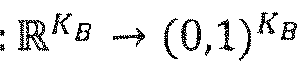

- For gradient updates, we will try to minimize the sum of the rate of the residue and the cross entropy of the mode kopt with respect to the latter probability distribution. Thus we define our loss function LossB for the block B as


- Given the loss function in (5), we determine the weights
 we are given a set of training examples


1.3 Specification of the Functions

- In this section, we define the form of the functions


neural networks - By an affine transformation





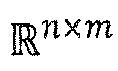


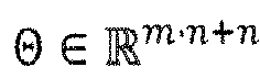

- By a non-linear activation function


- Here, (Act(x)) i denotes the i-th component of Act(x) and xi denotes the i-th component of x. Finally,




- Our function


- Here,


neural network 80i parametrized using paramters Θ. It would be a sequence of linear functions Aff Θj and non-linear functions ρ, which, in the present example, are applied alternatingly in the sequence, wherein the parameters Θ comprise the linear function weights in Aff Θj In the sequence of linear functions Aff Θj and non-linear functions ρ, the pairs of a linear function Aff Θj followed by non-linear function ρ would represent a neuron layer, for example, such as the j-th layer, with the number of predecessor nodes preceding this neuron layer j in feed-forward direction of the neural network being determined by dimension m of Aff Θj , the number of columns of Aff Θj , and the number of neurons of the neuron layer j itself being determined by dimension n of Aff Θj , the number of its rows. Each row of Aff Θj incorpartes the weights controlling as to how strong a signal strength respectively activation of each of the m predecessor neurons is forwarded to the respective neuron of the neuron layer j which corresponds to the respective row. ρ controlls for each neuron of neuron layer j the non-linear mapping of its linear combination of forwarded predecessor neuron activations onto its own activation. In the above example, there are k such neuron layers. The number of neurons per layer may vary. The number of nuron layers k may vary among the variousneural networks 80j, i.e. for different j. Note, that the non-linear function might vary per neurion layer or even per neuron or at some other units. - Similarly, our function



- Here,



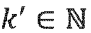
neural network 84 parametrized using paramters Ψ . It would be a sequence of linear functions Aff Ψj and non-linear functions ρ, just as it has been described above with respect to the neuron layers concerning the prediction signal computation. The number of neuron layers k' ofneural network 84 may differ from one or more of the number of neuron layers k ofneural networks 80i, - We extended the algorithm of the previous section so that we can train predictions that complement already existing intra predictions.
- Namely, let


 (im, rec, k) models the loss of the k-th intra prediciont function

- Then we extend the loss function from (5) to the loss function


- Keeping the notations from the end of the previous section, we determine weights


- For that purpose, we typically firstly find the weights by optimizing (6) and then initialize with those weights to find the weights that optimize (10).
- In this section we described how, in the training of our predictions, one may take into account that in a typical video coding standard it is usually possible to split a block into smaller subblocks in various ways and to perform an intra prediction on the smaller subblocks.
- Namely, assume that for some





- We assume that there exists a block
 . Then for B ∈
 we assume that a set


- For a given color component, let im be an image on B max, which, by restriction, we regard as an image im| Bl on Bi for each


- Keeping the notations of section 1.2, for each B ∈we seek

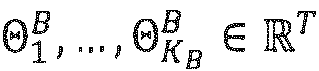

 jointly as follows. For B ∈
 and given sets of weights
 , B' ⊆ B, 1 ≤ k ≤ KB,, we put

- Moreover, for B' ⊂ B we define ΘB | B' ⊂ Θ B as

- As in section 1.4, we assume that for each B ∈a possibly empty set



- Then we define a loss-function
 via the inclusion of sets. Let
 . For B ∈
 we put

- Next, let B ∈and assume that LossB,total is already defined for all B' ∈
 with B' ⊆ B.
- Then we define


- Finally, given a fixed set of training examples

max , Ψ Bmax by minimizing or at least making small the expression
- We typically initialize the weights
 individually.
- We consider a hybrid video coding standard in which for a given color component the content of a video signal on a given block


current block B 10. Then we claim copyright for the following steps that a decoder can perform in order to generate a prediction signal pred on B, which we regard as an element of
- 1. The decoder has at its disposal fixed numbers KB,


weights 

- 2. The decoder reconstructs from the bitstream a flag that is part of
side information 70 and indicates whether exactly one of the following options is true: [label=)]- (i) One of the predictions

set 72 - (ii) None of the predictions

- (i) One of the predictions
- Here, the functions

- 3. If Option Two in
step 2 is true, the decoder proceeds for the givenblock 10 as in the underlying hybrid video coding standard. - 4. If Option One in
step 2 is true, the decoder applies the function


- (i) The decoder defines a probability distribution


side information 70 via the entropy coding engine used in the underlying standard from thedatastream 12 and defines m: = k. - (ii) The decoder defines a permutation







- (i) The decoder defines a probability distribution
- Then the decoder reconstructs from the bitstream 12 a unique index i ∈ {1, ..., KB } that Is also part of
datastream 12 and puts m: = σ(i). - In the code design to parse the latter index i, it is required that the number of bits needed to signal an index i 1 ∈ {1, ..., KB } is less or equal than the number of bits to signal an index i 2 ∈ {1, ..., KB } if σ(i 1) ≤ σ(i 2) and if all involved underlying probabilities used by the entropy coding engine are set to equal probability.
- 5. If Option One in
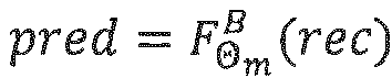
step 2 is true and if the decoder has determined the index m according to the previous step 4, the decoder generates 71 the prediction signal pred ∈
neural network 80m. Then the decoder proceeds as in the underlying hybrid video coding standard using pred as prediction signal. - The integration of intra prediction functions whose design is based on a data driven learning approach into an existing hybrid video codec. The description had two main parts. In the first part, we described a concrete algorithm for an offline training of intra prediction functions. In the second part, we described how a video decoder may use the latter prediction functions in order to generate a prediction signal for a given block.
- Thus, what has been described above in sections 1.1 to 2, is, inter alia, an apparatus for block-wise decoding a
picture 10 from adatastream 12. Theapparatus 54 supports a plurality of intra-prediction modes comprising, at least, aset 72 of intra-prediction modes according to which the intra-prediction signal for acurrent block 18 of thepicture 10 is determined by applying afirst set 60 of neighboring samples of thecurrent block 18 onto aneural network 80i. Theapparatus 54 is configured to select 68 for thecurrent block 18 one intra-prediction mode out of theplurality 66 of intra-prediction modes and predicts 71 thecurrent block 18 using the one intra-prediction mode, namely using the correspondingneural network 80m having been selected. Although the decoder presented insection 2, hadintra-prediction modes 74 within theplurality 66 of intra-prediction modes supported in addition to the neural network-based ones inset 72, this has been merely an example and needs not to be the case. Further, the above description insections decoder 54 does not use, and does not comprise, the furtherneural network 84. With respect to the optimization described above, this means that the second adder in the inner quality presented in section 1.2 for finding-out
neural networks 80i in a manner so that the frequency of selection would appropriately follow a code rate indication of MB. For instance, thedecoder 54 could decode fromdatastream 12 an index forblock 18 using a variable length code, the code length of which are indicated in MB, and thedecoder 54 would perform theselection 68 based on this index. The index would be part of theside information 70. - A further alternative to the description brought forward above in
section 2 is that thedecoder 54 may alternatively derive a ranking among the set 72 of neural network-based intra-prediction modes depending on a first portion of the datastream which relates to a neighborhood of thecurrent block 18 in order to obtain an ordered list of intra-prediction modes with selecting the intra-prediction mode finally to be used out of the ordered list of intra-prediction modes depending on a second portion of the datastream other than the first portion. The "first portion" may, for instance, relate to a coding parameter or prediction parameter related to one or more block neighboringcurrent block 18. The "second portion" may then be an index, for instance, pointing into, or being an index of, the neural network-based intra-prediction mode set 72. When construed in alignment with above-outlinedsection 2, thedecoder 54 comprises the furtherneural network 84 which determines, for each intra-prediction mode of theset 72 of intra-prediction modes, a probability value by applying set 86 of neighboring samples thereonto and ordering these probability values in order to determine a rank for each intra-prediction mode ofset 72, thereby obtaining an ordered list of intra-prediction modes. An index in thedatastream 12 as part ofside information 70 is then used as an index into the ordered list. Here, this index may be coded using variable length code for which MB indicates the code length. And as explained above insection 2, in item 4i, according to a further alternative embodiment,decoder 54 may use the just-mentioned probability values determined by the furtherneural network 84 for each neural network-based intra-prediction mode ofset 72 so as to efficiently perform entropy coding of the index intoset 72. In particular, the symbol alphabet of this index which is part of theside information 70 and used as an index intoset 72, would comprise a symbol or value for each of the modes withinset 72, and the probability values provided byneural network 84 would, in case ofneural network 84 design according to the above description, provide probability values which would lead to efficient entropy coding in that these probability values closely represent the actual symbol statistics. For this entropy coding, arithmetic coding could be used, for instance, or probability interval partitioning entropy (PIPE) coding. - Favorably, no additional information is necessary for any of the intra-prediction modes of
set 72. Eachneural network 80i, once advantageously parametrized for encoder and decoder in accordance with, for example, the above description insections current block 18 without any additional guidance in the datastream. As already denoted above, the existence of other intra-prediction modes besides the neural network-based ones inset 72 is optional. They have been indicated above byset 74. In this regard, it should be noted that one possible way of selecting set 60, i.e. the set of neighboring samples forming the input for the intra-prediction 71, may be selected such that this set 60 is the same for the intra-prediction modes ofset 74, i.e. the heuristic ones, withset 60 for the neural network-based intra-prediction modes being larger in terms of the number of neighboring samples included inset 60 and influencing theintra-prediction 71. In other words, the cardinality ofset 60 may be larger for neural network-basedintra-prediction modes 72 compared to the other modes ofset 74. For instance, set 60 of any intra-prediction mode ofset 74 may merely comprise neighboring samples along a one-dimensional line extending alongside to sides ofblock 18 such as the left hand one and the upper one. Set 60 of the neural network-based intra-prediction modes may cover an L-shaped portion extending alongside the just-mentioned sides ofblock 18 but being wider than just one-sample wide asset 60 for the intra-prediction modes ofset 74. In this manner, neural network-based intra-prediction modes may result into a better intra-prediction with a correspondingly lower prediction residual. - As described above in
section 2, theside information 70 conveyed in thedatastream 12 to anintra-predicted block 18 may comprise a fleck which generally indicates whether the selected intra-prediction mode forblock 18 is member ofset 72 or member ofset 74. This fleck is, however, merely optional withside information 70 indicating, for instance, an index into awhole plurality 66 of intra-prediction modes including bothsets - The just-discussed alternatives are, in the following, briefly discussed with respect to the
Figs. 7a to 7d . The Figs. define both, decoder and encoder concurrently, namely in terms of their functionality with respect to anintra-predicted block 18. The differences between the encoder mode of operation and the decoder mode of operation with respect to anintra-coded block 18 is, on the one hand, the fact that the encoder performs all or at least some of theintra-prediction modes 66 available so as to determine at 90 a best one in terms of, for instance, some cost function minimizing sense, and that the encoder formsdata stream 12, i.e., codes date there into, while the decoder derives the data therefrom by decoding and reading, respectively.Fig. 7a shows the mode of operation for the above-outlined alternative according to which aflag 70a within theside information 70 forblock 18 indicates whether the intra-prediction mode determined to be the best mode forblock 18 by the encoder instep 90, is withinset 72, i.e., is neural network based intra-prediction mode, or withinset 74, i.e., one of the non-neural network based intra-prediction modes. The encoder insertsflag 70a intodata stream 12 accordingly, while the decoder retrieves it therefrom.Fig. 7a assumes that thedetermined intra-prediction mode 92 is withinset 72. The separateneural network 84 then determines a probability value for each neural network based intra-prediction mode ofset 72 and using these probability values set 72 or, to be more precise, the neural network based intra-prediction modes therein are ordered according to their probability values such as in descending order of their probability values, thereby resulting into an orderedlist 94 of intra-prediction modes. Anindex 70b being part of theside information 70 is then coded by the encoder intodata stream 12 and decoded therefrom by the decoder. The decoder, accordingly, is able to determine which set ofsets block 18 is located in, and to perform the ordering 96 ofset 72 in case of the intra-prediction mode to be used being located inset 72. It might be that an index is also transmitted indata stream 12 in case of the determined intra-prediction mode being located inset 74. Thus, the decoder is able to generate the prediction signal forblock 18 using the determined intra-prediction mode by controlling theselection 68 accordingly. -
Fig. 7b shows an alternative according to which theflag 70a is not present indata stream 12. Instead, the orderedlist 94 would not only comprise the intra-prediction modes ofset 72, but also intra-prediction modes ofset 74. The index withinside information 70 would be an index into this greater ordered list and indicate the determined intra-prediction mode, i.e., the one determined beoptimization 90. In case ofneural network 84 providing a probability value for the neural network based intra-prediction mode within 72 only, the ranking between intra-prediction modes ofset 72 relative to the intra-prediction modes ofset 74 may be determined by other means such as inevitably arranging the neural network based intra-prediction modes ofset 72 to precede the modes ofset 74 in theorder list 94 or to arrange them alternatingly relative to each other. That is, the decoder is able to derive the index fromdata stream 12, use theindex 70 as in index into theorder list 94 with deriving theorder list 94 from the plurality ofintra-prediction modes 66 using the probability values output byneural network 84.Fig. 7c shows a further variant.Fig. 7c show a case of not usingflag 70a, but the flag could be used alternatively. The issue whichFig. 7c is directed pertains to the possibility that neither encoder nor decoder usesneural network 84. Rather, the ordering 96 is derived by other means such as coding parameters conveyed withindata stream 12 with respect to one or more neighboring blocks 18, i.e.,portions 98 of adata stream 12 which pertains to such one or more neighboring blocks. -
Fig. 7d shows a further variant ofFig. 7a , namely the one according to which theindex 70b is coded using entropy coding and decoded fromdata stream 12 using entropy decoding, commonly denoted usingreference sign 100. The sample statistics or the probability distribution used for theentropy coding 100 is controlled by the probability values output byneural network 84 as explained above, this renders the entropy coding ofindex 70b very efficient. - For all embodiments 7a to 7d it is true that set 74 modes may not be present. Accordingly, the
respective module 82 may be missing andflag 70a would be unnecessary anyway. - Further, although not shown in any Fig., it is clear that the
mode selection 68 at the encoder and decoder could be synchronized to each other even without anyexplicit signaling 70, i.e., without spending any side information. Rather, the selection could be derived from other means such as by taking inevitably the first one of the orderedlist 94, or by deriving the index into theorder list 94 on the basis of coding parameters relating to one or more neighboring blocks.Fig. 8 shows an apparatus for designing the set of intra-prediction modes ofset 72 to be used for the block-based picture coding. Theapparatus 108 comprises aparameterizable network 109 which inherits or comprises parameterizable versions ofneural networks 800 to 80KB-1 as well asneural network 84. Here, inFig. 8 , depicted as individual units, i.e.,neural network 840 for providing the probability value for neural network basedintra-prediction mode 0 toneural network 84KB-1 for providing the probability value associated with the neural network based intra-prediction mode KB-1. Theparameters 111 for parametrizingneural networks 84 and theparameters 113 for parametrizingneural networks 800 to 80KB-1 are input or applied to respective parameter inputs of these neural networks by anupdater 110.Apparatus 108 has access to a reservoir or a plurality of picture test blocks 114 along with corresponding neighboring samples sets 116. Pairs of theseblocks 114 and their associated neighboring sample sets 116 are sequentially used byapparatus 108. In particular, a currentpicture test block 114 is applied to parameterizableneural network 109 so thatneural networks 80 provide aprediction signal 118 for each neural network based intra-prediction mode ofset 72, and eachneural network 80 provides a probability value for each of these modes. To this end, these neural networks use theircurrent parameters - In the above description rec has been used to denote the
picture test block 114, and

probability value 120. For eachmode 0...Kb-1, there is acost estimator 122 comprised byapparatus 108 which computes a cost estimate for the respective mode on the basis of theprediction signal 118 obtained for the respective mode. In the above example,cost estimators 122 computed the cost estimates as indicated on the left and right hand sides of the inequality in section 1.2. That is, here, thecost estimators 122 also used, for each mode, thecorresponding probability value 120. This needs not, however, to be case as already discussed above. The cost estimate, however, is in any case a sum of two add-ins, one of which is an estimate of the coding cost for the prediction residual indicated as the term with R̃ in the above inequality, and another add-in estimating the coding costs for indicating the mode. In order to compute the estimate for the coding cost related to the prediction residual, thecost estimators 122 also obtain the original content of the currentpicture test block 114. Theneural networks cost estimate 124 as output bycost estimators 122 is received by aminimum cost selector 126 which determines the mode minimizing or having minimum cost estimate associated therewith. In the above mathematical notation, this has been
prediction signal 118 obtained for the intra-prediction mode of lowest coding estimate, and a second add-in forming a mode signaling side information rate estimate depending on the prediction signal and the probability value obtained for the intra-prediction mode of lowest coding cost estimate as indicated byselector 126. As indicated above, this may be done using a gradient distant. The coding cost function is, thus, differentiable and in the above mathematical representation an example of this function was given in equation 5. Here, the second add-in relating to the mode signaling side information rate estimate computed the cross entropy for the intra-prediction mode of lowest coding cost estimate. - Thus, the
updater 110 seeks to updateparameters parameters neural network 109 so as to process the next picture test block of theplurality 112. As discussed above with respect to section 1.5, there may be a mechanism controlling that primarily those pairs of picture test blocks 114 and their associated neighboring sample sets 116 are applied for the recursive update process for which the intra-prediction is, in rate distortion sense, preferably done without any block sub-division, thereby avoiding that theparameters - So far, the above-discussed embodiments primarily concern cases where encoder and decoder had within their supported intra-prediction modes 66 a set of neural network-based intra-prediction modes. In accordance with the embodiments discussed with respect to
Figs. 9a and9b this needs not to be the case necessarily.Fig. 9a seeks to outline the mode of operation of an encoder and a decoder in accordance with an embodiment wherein the description thereof is provided in a manner focusing on the differences to the description brought forward above with respect toFig. 7a . Theplurality 66 of supported intra-prediction modes may or may not comprise neural network-based intra-prediction modes and may or may not comprise non-neural network-based intra-prediction modes. Themodules 170 inFig. 9a comprised by encoder and decoder, respectively, in order to provide for each of the supportedmodes 66 the corresponding prediction signal are, accordingly, not necessarily neural networks. As already denoted above, such intra-prediction modes may be neural network-based or they may be heuristically motivated and compute the prediction signal based on a DC intra-prediction mode or an angular intra-prediction mode or any other. Accordingly, thesemodules 170 could be denoted as prediction signal computer. Encoder and decoder in accordance with the embodiment ofFig. 9a , however, comprise aneural network 84. Theneural network 84 computes, on the basis of the neighboring sample set 86, probability values for the supportedintra-prediction modes 66 so that theplurality 66 of intra-prediction modes may be turned into the orderedlist 94. Theindex 70 withindatastream 12 forblock 18 points into this orderedlist 94. Theneural network 84, thus, assists in lowering the side information rate to be spent for the intra-prediction mode signalization. -
Fig. 9b shows an alternative toFig. 9a in that instead of the ordering, entropy de/encoding 100 of theindex 70 is used with controlling the probability or simple statistics thereof, i.e. controlling the entropy probability distribution for entropy de/encoding in en/decoder, according to the probability values determined for theneural network 84 for each mode ofplurality 66. -
Fig. 10 shows an apparatus for designing or parametrizingneural network 84. It is, thus, anapparatus 108 for designing a neural network for assisting in selecting among aset 66 of intra-prediction modes. Here, for each mode ofset 66 there is a corresponding neural network block together formingneural network 84 and the parametrizableneural network 109 ofapparatus 108 is merely parametrizable with respect these blocks. For each mode, there is also theprediction signal computer 170 which needs, however, not to be parametrizable according toFig. 10 . Thus,apparatus 108 ofFig. 10 computes costs estimates for each mode on the basis of theprediction signal 118 as computed by the correspondingprediction signal computer 170 and, optionally, on the basis of the corresponding probability value as determined by the corresponding neural network block for this mode. On the basis of the resulting costs estimates 124, theminimum cost selector 126 selects the mode of the minimum cost estimate and theupdater 110 updates theparameters 111 for the neural 84. - The following is noted with respect to the description of
Figs. 7a to 7d and9a and9b . A common feature of the embodiments ofFigs. 9a and9b which is also used by some of the embodiments ofFigs. 7a to 7d was the fact that the probability values of the neural network values in order to improve or reduce the overhead associated with theside information 70 for signaling the mode determined on the encoder side at theoptimization process 90 to the decoder. As indicated above with respect to the embodiments ofFigs. 7a to 7d , however, it should be clear that the embodiments ofFigs. 9a and9b may be varied to the extent that noside information 70 is spent indatastream 12 with respect to the mode selection at all. Rather, the probability values output byneural network 84 for each mode may be used to synchronize the mode selection between encoder and decoder inevitably. In that case, there would be nooptimization decision 90 at the encoder side with respect to the mode selection. Rather, the mode to be used among set 66 would be determined on encoder and decoder side in the same manner. A similar statement is true with respect to corresponding embodiments ofFigs. 7a to 7d when varied so as to not use anyside information 70 indatastream 12. Back to the embodiments ofFigs. 9a and9b , it is interesting, however, that while theselection process 68 at the decoder side is dependent on the probability values output by the neural network in that the ordering or the probability distribution estimate dependency on the probability values varies the interpretation of the side information, as far as the encoder is concerned, the dependency on the probability values may not only affect the coding of theside information 70 intodatastream 12 using, for instance, a respective variable length coding of an index into the ordered list or using entropy en/decoding with a probability distribution estimation depending on the neural network's probability values, but also the optimization step 90: here, the code rate for transmittingside information 70 may be taken into account and may, thus, influence thedetermination 90. - Although some aspects have been described in the context of an apparatus, it is clear that these aspects also represent a description of the corresponding method, where a block or device corresponds to a method step or a feature of a method step. Analogously, aspects described in the context of a method step also represent a description of a corresponding block or item or feature of a corresponding apparatus. Some or all of the method steps may be executed by (or using) a hardware apparatus, like for example, a microprocessor, a programmable computer or an electronic circuit. In some embodiments, one or more of the most important method steps may be executed by such an apparatus.
- The inventive encoded data stream can be stored on a digital storage medium or can be transmitted on a transmission medium such as a wireless transmission medium or a wired transmission medium such as the Internet.
- Depending on certain implementation requirements, embodiments of the invention can be implemented in hardware or in software. The implementation can be performed using a digital storage medium, for example a floppy disk, a DVD, a Blu-Ray, a CD, a ROM, a PROM, an EPROM, an EEPROM or a FLASH memory, having electronically readable control signals stored thereon, which cooperate (or are capable of cooperating) with a programmable computer system such that the respective method is performed. Therefore, the digital storage medium may be computer readable.
- Some embodiments according to the invention comprise a data carrier having electronically readable control signals, which are capable of cooperating with a programmable computer system, such that one of the methods described herein is performed.
- Generally, embodiments of the present invention can be implemented as a computer program product with a program code, the program code being operative for performing one of the methods when the computer program product runs on a computer. The program code may for example be stored on a machine readable carrier.
- Other embodiments comprise the computer program for performing one of the methods described herein, stored on a machine readable carrier.
- In other words, an embodiment of the inventive method is, therefore, a computer program having a program code for performing one of the methods described herein, when the computer program runs on a computer.
- A further embodiment of the inventive methods is, therefore, a data carrier (or a digital storage medium, or a computer-readable medium) comprising, recorded thereon, the computer program for performing one of the methods described herein. The data carrier, the digital storage medium or the recorded medium are typically tangible and/or non-transitionary.
- A further embodiment of the inventive method is, therefore, a data stream or a sequence of signals representing the computer program for performing one of the methods described herein. The data stream or the sequence of signals may for example be configured to be transferred via a data communication connection, for example via the Internet.
- A further embodiment comprises a processing means, for example a computer, or a programmable logic device, configured to or adapted to perform one of the methods described herein.
- A further embodiment comprises a computer having installed thereon the computer program for performing one of the methods described herein.
- A further embodiment according to the invention comprises an apparatus or a system configured to transfer (for example, electronically or optically) a computer program for performing one of the methods described herein to a receiver. The receiver may, for example, be a computer, a mobile device, a memory device or the like. The apparatus or system may, for example, comprise a file server for transferring the computer program to the receiver.
- In some embodiments, a programmable logic device (for example a field programmable gate array) may be used to perform some or all of the functionalities of the methods described herein. In some embodiments, a field programmable gate array may cooperate with a microprocessor in order to perform one of the methods described herein. Generally, the methods are preferably performed by any hardware apparatus.
- The apparatus described herein may be implemented using a hardware apparatus, or using a computer, or using a combination of a hardware apparatus and a computer.
- The apparatus described herein, or any components of the apparatus described herein, may be implemented at least partially in hardware and/or in software.
- The methods described herein may be performed using a hardware apparatus, or using a computer, or using a combination of a hardware apparatus and a computer.
- The methods described herein, or any components of the apparatus described herein, may be performed at least partially by hardware and/or by software.
- The above described embodiments are merely illustrative for the principles of the present invention. It is understood that modifications and variations of the arrangements and the details described herein will be apparent to others skilled in the art. It is the intent, therefore, to be limited only by the scope of the impending patent claims and not by the specific details presented by way of description and explanation of the embodiments herein.
Claims (8)
- Method for training a first neural network (80) for each of a set (72) of intra-prediction modes for block-based picture coding for determining an intra-prediction signal (118) for a current block (18) by applying a first set (60) of neighboring samples (116) of the current block (18) onto the first neural network (80, 800, 80KB-1) for the respective intra-prediction mode, comprisingapplying, for each of the set (72) of intra-prediction modes, a first set (60) of neighboring samples (116) neighboring a first picture test block (114) onto the first neural network (80) for the respective intra-prediction mode so as to obtain, for each of the set (72) of intra-prediction modes, a prediction signal (118) for the first test block, and a second set (86) of neighboring samples neighboring the first picture test block onto a second neural network (84, 840, 84KB-1) so as to obtain, for each of the set (72) of intra-prediction modes, a probability value (120) indicative of a probability of the respective intra-prediction mode;determining (122), for each of the set (72) of intra-prediction modes, a coding cost estimate (124) for coding costs related to prediction error coding and mode signalization using the prediction signal (118) obtained for the respective intra-prediction mode;updating (110) first parameters (113) of the first neural network (80) for each of the set of intra-prediction modes and second parameters (111) of the second neural network (84) so as to reduce a coding cost function having (i) a first addend forming a residual rate estimate depending on the prediction signal (118) obtained for an intra-prediction mode of the lowest coding cost estimate and (ii) a second addend forming a mode signaling side information rate estimate depending on the prediction signal (118) and the probability value (120) obtained for the intra-prediction mode of the lowest coding cost estimate; andsequentially repeating the applying, determining and updating for a plurality of picture tests blocks with using the first and second parameters (113, 111) as updated for one picture test block for the application of the next picture test block of the plurality of picture test blocks.
- Apparatus (108) for training a first neural network (80) for each of a set (72) of intra-prediction modes for block-based picture coding for determining an intra-prediction signal for a current block (18) by applying a first set (60) of neighboring samples of the current block (18) onto the first neural network (80, 800, 80KB-1) for the respective intra-prediction mode, the apparatus comprising:a parameterizable neural network (109) configured to apply, for each of the set (72) of intra-prediction modes, a first set (60) of neighboring samples (116) neighboring a first picture test block (114) onto the first neural network (80) for the respective intra-prediction mode so as to obtain, for each of the set (72) of intra-prediction modes, a prediction signal (118) for the first test block, and a second set (86) of neighboring samples neighboring the first picture test block onto a second neural network (84, 840, 84KB-1) so as to obtain, for each of the set (72) of intra-prediction modes, a probability value (120) indicative of a probability of the respective intra-prediction mode;a cost estimator (122) configured to determine, for each of the set (72) of intra-prediction modes, a coding cost estimate (124) for coding costs related to prediction error coding and mode signalization using the prediction signal (118) obtained for the respective intra-prediction mode; andan updater (110) configured to update (110) first parameters (113) of the first neural network (80) for each of the set (72) of intra-prediction modes and second parameters (111) of the second neural network (84) so as to reduce a coding cost function having (i) a first addend forming a residual rate estimate depending on the prediction signal (118) obtained for an intra-prediction mode of the lowest coding cost estimate indicated by a selector (126) and (ii) a second addend forming a mode signaling side information rate estimate depending on the prediction signal (118) and the probability value (120) obtained for the intra-prediction mode of the lowest coding cost estimate indicated by the selector (126),wherein the updater (110), the parameterizable neural network (109), the cost estimator (122) and the selector (126) are configured to sequentially repeat the application, determination and updating for a plurality of picture tests blocks with using the first and second parameters (113, 111) as updated for one picture test block for the application of the next picture test block of the plurality of picture test blocks.
- Apparatus of claim 2, configured to apply the first set (60) of neighboring samples (116) onto the first neural network (80) and the second set (86) of neighboring samples onto the second neural network (84) wherein
the first and second neural networks (80, 84) aresequences of linear and non-linear functions, wherein the first and second parameters (113, 111) comprise weights of the linear functions.sequences of linear and non-linear functions forming a sequence of neuron layers, orsequences of layers of neurons, wherein the first and second parameters (113, 111) comprise weights controlling a signal strength forwarding between interconnected neurons. - Apparatus of claim 2 or 3, wherein
the cost estimator (122) is further configured to:- determine, for each of the set (72) of intra-prediction modes, the cost estimate for coding costs related to prediction error coding and mode signalization using the prediction signal (118) and the probability value (120) obtained for the respective intra-prediction mode, and/or- determine, for each of the set (72) of intra-prediction modes, the cost estimate for coding costs related to prediction error coding and mode signalization as a sum of a first addend mapping the prediction signal (118) obtained for the respective intra-prediction mode and an original undistorted version of the first picture test block onto a prediction error coding rate estimate and a second addend mapping the probability value (120) obtained for the respective intra-prediction mode onto a mode signalization rate estimate. - Apparatus of any of claims 2 to 4, wherein
the coding cost function's second addend forms the mode signaling side information rate estimate depending on the prediction signal (118) obtained for the intra-prediction mode of lowest coding cost estimate as a function of the probability values (120) obtained for all intra prediction modes which indicates a cross entropy for the intra-prediction mode of lowest coding cost estimate. - Apparatus of any of claims 2 to 5, wherein
the coding cost function's first addend forms the residual rate estimate depending on the prediction signal (118) obtained for the intra-prediction mode of lowest coding cost estimate as a function of the prediction signal (118) obtained for the respective intra-prediction mode and an original undistorted version of the first picture test block. - Apparatus of any of claims 2 to 6, wherein
the updater (110) is configured to subdivide the plurality of picture test blocks into a first set more efficiently codable unsubdivided, and a second set more efficiently codable subdivided into subblocks, and sequentially repeating the application, determination and updating for picture test blocks of the first set with using the first and second parameters (113, 111) as updated for one picture test block for the application of the next picture test block of the first set. - Apparatus of any of claims 2 to 7, wherein
the updater (110) is configured to perform the update using a gradient descent.
Priority Applications (1)
| Application Number | Priority Date | Filing Date | Title |
|---|---|---|---|
| EP25163579.3A EP4546785A3 (en) | 2017-10-13 | 2018-10-10 | Intra-prediction mode concept for block-wise picture coding |
Applications Claiming Priority (2)
| Application Number | Priority Date | Filing Date | Title |
|---|---|---|---|
| EP17196402 | 2017-10-13 | ||
| PCT/EP2018/077609 WO2019072921A1 (en) | 2017-10-13 | 2018-10-10 | Intra-prediction mode concept for block-wise picture coding |
Related Child Applications (1)
| Application Number | Title | Priority Date | Filing Date |
|---|---|---|---|
| EP25163579.3A Division EP4546785A3 (en) | 2017-10-13 | 2018-10-10 | Intra-prediction mode concept for block-wise picture coding |
Publications (2)
| Publication Number | Publication Date |
|---|---|
| EP3695599A1 EP3695599A1 (en) | 2020-08-19 |
| EP3695599B1 true EP3695599B1 (en) | 2025-04-09 |
Family
ID=60083873
Family Applications (2)
| Application Number | Title | Priority Date | Filing Date |
|---|---|---|---|
| EP25163579.3A Pending EP4546785A3 (en) | 2017-10-13 | 2018-10-10 | Intra-prediction mode concept for block-wise picture coding |
| EP18789026.4A Active EP3695599B1 (en) | 2017-10-13 | 2018-10-10 | Intra-prediction mode concept for block-wise picture coding |
Family Applications Before (1)
| Application Number | Title | Priority Date | Filing Date |
|---|---|---|---|
| EP25163579.3A Pending EP4546785A3 (en) | 2017-10-13 | 2018-10-10 | Intra-prediction mode concept for block-wise picture coding |
Country Status (7)
| Country | Link |
|---|---|
| US (3) | US11363259B2 (en) |
| EP (2) | EP4546785A3 (en) |
| JP (1) | JP7210568B2 (en) |
| KR (1) | KR102454936B1 (en) |
| CN (2) | CN111466115B (en) |
| TW (2) | TWI702824B (en) |
| WO (1) | WO2019072921A1 (en) |
Families Citing this family (32)
| Publication number | Priority date | Publication date | Assignee | Title |
|---|---|---|---|---|
| KR102698963B1 (en) | 2018-03-29 | 2024-08-27 | 프라운호퍼 게젤샤프트 쭈르 푀르데룽 데어 안겐반텐 포르슝 에. 베. | Intra-prediction mode concept for block-wise picture coding |
| KR20200028856A (en) * | 2018-09-07 | 2020-03-17 | 김기백 | A method and an apparatus for encoding/decoding video using intra prediction |
| MX2021002931A (en) | 2018-09-13 | 2021-07-16 | Fraunhofer Ges Forschung | AFFINED LINEAR WEIGHTED INTRAPREDICTION. |
| US11599773B2 (en) | 2018-12-27 | 2023-03-07 | Micron Technology, Inc. | Neural networks and systems for decoding encoded data |
| EP3987808A4 (en) * | 2019-06-19 | 2023-07-05 | Nokia Technologies Oy | METHOD, DEVICE AND COMPUTER PROGRAM PRODUCT FOR VIDEO ENCODING AND VIDEO DECODING |
| CN110708559B (en) * | 2019-09-03 | 2022-03-25 | 北京达佳互联信息技术有限公司 | Image processing method, device and storage medium |
| WO2021069688A1 (en) | 2019-10-11 | 2021-04-15 | Interdigital Vc Holdings France, Sas | Deep intra predictor generating side information |
| US20220398455A1 (en) * | 2019-11-07 | 2022-12-15 | Interdigital Vc Holdings France, Sas | Iterative training of neural networks for intra prediction |
| US11424764B2 (en) | 2019-11-13 | 2022-08-23 | Micron Technology, Inc. | Recurrent neural networks and systems for decoding encoded data |
| JP7479471B2 (en) * | 2019-12-06 | 2024-05-08 | フラウンホッファー-ゲゼルシャフト ツァ フェルダールング デァ アンゲヴァンテン フォアシュンク エー.ファオ | Mode - Matrix-based intra prediction with global settings |
| EP4107947A4 (en) * | 2020-02-21 | 2024-03-06 | Nokia Technologies Oy | METHOD, APPARATUS AND COMPUTER PROGRAM PRODUCT FOR VIDEO ENCODING AND DECODING |
| EP4107945A1 (en) * | 2020-02-21 | 2022-12-28 | InterDigital VC Holdings France | Neural network-based intra prediction for video encoding or decoding |
| CN111800642B (en) * | 2020-07-02 | 2023-05-26 | 中实燃气发展(西安)有限公司 | HEVC intra-frame intra-angle mode selection method, device, equipment and readable storage medium |
| US12206894B2 (en) | 2020-09-23 | 2025-01-21 | Electronics And Telecommunications Research Institute | Apparatus, method and storage medium for image encoding/decoding to perform intra prediction using artificial neutral network |
| CN114286099B (en) * | 2020-09-28 | 2025-03-21 | 华为技术有限公司 | Intra-frame prediction method and device |
| US12062150B2 (en) * | 2020-09-30 | 2024-08-13 | Tencent America LLC | Method and apparatus for block-wise neural image compression with post filtering |
| CN114584776B (en) * | 2020-11-30 | 2025-02-25 | 华为技术有限公司 | Intra-frame prediction mode decoding method and device |
| US20220201295A1 (en) * | 2020-12-21 | 2022-06-23 | Electronics And Telecommunications Research Institute | Method, apparatus and storage medium for image encoding/decoding using prediction |
| US11496746B2 (en) * | 2021-02-02 | 2022-11-08 | Qualcomm Incorporated | Machine learning based rate-distortion optimizer for video compression |
| CN114915782B (en) * | 2021-02-10 | 2025-09-12 | 华为技术有限公司 | Coding method, decoding method and device |
| WO2022225025A1 (en) * | 2021-04-23 | 2022-10-27 | パナソニック インテレクチュアル プロパティ コーポレーション オブ アメリカ | Image decoding method, image coding method, image decoder, and image encoder |
| US11973513B2 (en) | 2021-04-27 | 2024-04-30 | Micron Technology, Inc. | Decoders and systems for decoding encoded data using neural networks |
| US11563449B2 (en) | 2021-04-27 | 2023-01-24 | Micron Technology, Inc. | Systems for error reduction of encoded data using neural networks |
| WO2022229707A1 (en) * | 2021-04-28 | 2022-11-03 | Interdigital Vc Holdings France, Sas | Interactions between neural network-based intra prediction modes and regular intra prediction modes |
| WO2022257134A1 (en) * | 2021-06-11 | 2022-12-15 | Oppo广东移动通信有限公司 | Video encoding/decoding method, device and system, and storage medium |
| EP4381740A1 (en) * | 2021-10-05 | 2024-06-12 | Sony Group Corporation | Adaptive mode selection for point cloud compression |
| US11755408B2 (en) * | 2021-10-07 | 2023-09-12 | Micron Technology, Inc. | Systems for estimating bit error rate (BER) of encoded data using neural networks |
| WO2023134731A1 (en) * | 2022-01-13 | 2023-07-20 | Mediatek Inc. | In-loop neural networks for video coding |
| US20250150586A1 (en) * | 2023-11-03 | 2025-05-08 | Tencent America LLC | Direction-adaptive region-based prediction combination |
| WO2025198317A1 (en) * | 2024-03-22 | 2025-09-25 | 동아대학교 산학협력단 | Video encoding/decoding method and device, and recording medium on which bitstream is stored |
| WO2025221098A1 (en) * | 2024-04-15 | 2025-10-23 | 현대자동차주식회사 | Method for coding intra-prediction mode by using history-based mpm candidates, and device using same |
| WO2026063623A1 (en) * | 2024-09-20 | 2026-03-26 | 현대자동차주식회사 | Image encoding/decoding method and device, and recording medium for storing bitstream |
Family Cites Families (17)
| Publication number | Priority date | Publication date | Assignee | Title |
|---|---|---|---|---|
| JP4735375B2 (en) * | 2006-04-04 | 2011-07-27 | 株式会社日立製作所 | Image processing apparatus and moving image encoding method. |
| JP2009111691A (en) * | 2007-10-30 | 2009-05-21 | Hitachi Ltd | Image encoding apparatus, encoding method, image decoding apparatus, and decoding method |
| JP5421757B2 (en) * | 2009-12-11 | 2014-02-19 | 株式会社Kddi研究所 | Image encoding device |
| JP5222870B2 (en) * | 2010-03-05 | 2013-06-26 | 日本放送協会 | Intra prediction apparatus, encoder, decoder, and program |
| KR101373814B1 (en) * | 2010-07-31 | 2014-03-18 | 엠앤케이홀딩스 주식회사 | Apparatus of generating prediction block |
| CN103262539A (en) * | 2010-12-17 | 2013-08-21 | 三菱电机株式会社 | Moving picture encoding device, moving picture decoding device, moving picture encoding method, and moving picture decoding method |
| US10171813B2 (en) | 2011-02-24 | 2019-01-01 | Qualcomm Incorporated | Hierarchy of motion prediction video blocks |
| JP5482735B2 (en) * | 2011-05-30 | 2014-05-07 | 株式会社Jvcケンウッド | Image decoding apparatus, image decoding method and image decoding program, and receiving apparatus, receiving method, and receiving program |
| GB2491391B (en) * | 2011-06-02 | 2014-09-03 | Canon Kk | Encoding mode values representing prediction modes |
| CA2898152C (en) | 2012-01-30 | 2018-02-20 | Samsung Electronics Co., Ltd. | Method and apparatus for video encoding for each spatial sub-area, and method and apparatus for video decoding for each spatial sub-area |
| CN107736027B (en) * | 2015-06-12 | 2021-06-01 | 松下知识产权经营株式会社 | Image encoding method, image decoding method, image encoding device, and image decoding device |
| CN105430415B (en) * | 2015-12-02 | 2018-02-27 | 宁波大学 | Fast encoding method in a kind of 3D HEVC deep video frames |
| KR102651878B1 (en) * | 2017-07-06 | 2024-03-28 | 삼성전자주식회사 | Method and device for encoding or decoding video |
| EP3776477A4 (en) * | 2018-04-09 | 2022-01-26 | Nokia Technologies Oy | An apparatus, a method and a computer program for video coding and decoding |
| US11240492B2 (en) * | 2019-01-22 | 2022-02-01 | Apple Inc. | Neural network based residual coding and prediction for predictive coding |
| WO2021140273A1 (en) * | 2020-01-10 | 2021-07-15 | Nokia Technologies Oy | A cascaded prediction-transform approach for mixed machine-human targeted video coding |
| CN111901592B (en) * | 2020-06-30 | 2023-01-17 | 北京大学 | Predictive coding neural network weight update method and device |
-
2018
- 2018-10-10 EP EP25163579.3A patent/EP4546785A3/en active Pending
- 2018-10-10 WO PCT/EP2018/077609 patent/WO2019072921A1/en not_active Ceased
- 2018-10-10 JP JP2020520774A patent/JP7210568B2/en active Active
- 2018-10-10 EP EP18789026.4A patent/EP3695599B1/en active Active
- 2018-10-10 CN CN201880079108.0A patent/CN111466115B/en active Active
- 2018-10-10 KR KR1020207013417A patent/KR102454936B1/en active Active
- 2018-10-10 CN CN202311664709.7A patent/CN117768643A/en active Pending
- 2018-10-11 TW TW107135727A patent/TWI702824B/en active
- 2018-10-11 TW TW109124384A patent/TWI794623B/en active
-
2020
- 2020-04-10 US US16/845,715 patent/US11363259B2/en active Active
-
2022
- 2022-06-13 US US17/839,459 patent/US11889066B2/en active Active
-
2023
- 2023-12-19 US US18/389,665 patent/US12659465B2/en active Active
Non-Patent Citations (2)
| Title |
|---|
| LI JIAHAO ET AL: "Intra prediction using fully connected network for video coding", 2017 IEEE INTERNATIONAL CONFERENCE ON IMAGE PROCESSING (ICIP), IEEE, 17 September 2017 (2017-09-17), pages 1 - 5, XP033322527, DOI: 10.1109/ICIP.2017.8296231 * |
| WENXUE CUI ET AL: "Convolutional Neural Networks Based Intra Prediction for HEVC", 2017 DATA COMPRESSION CONFERENCE (DCC), RESEARCHGATE, 1 April 2017 (2017-04-01), pages 436 - 436, XP055731498, Retrieved from the Internet <URL:https://www.researchgate.net/profile/Wenxue_Cui/publication/316899290_Convolutional_Neural_Networks_Based_Intra_Prediction_for_HEVC/links/5b8539aca6fdcc5f8b6c964a/Convolutional-Neural-Networks-Based-Intra-Prediction-for-HEVC.pdf> [retrieved on 20200917], DOI: 10.1109/DCC.2017.53 * |
Also Published As
| Publication number | Publication date |
|---|---|
| US20220321881A1 (en) | 2022-10-06 |
| TWI702824B (en) | 2020-08-21 |
| KR20200062322A (en) | 2020-06-03 |
| EP4546785A2 (en) | 2025-04-30 |
| TW201924331A (en) | 2019-06-16 |
| EP4546785A3 (en) | 2025-07-23 |
| US11363259B2 (en) | 2022-06-14 |
| JP2020537445A (en) | 2020-12-17 |
| US12659465B2 (en) | 2026-06-16 |
| TW202119818A (en) | 2021-05-16 |
| US20200244955A1 (en) | 2020-07-30 |
| CN117768643A (en) | 2024-03-26 |
| EP3695599A1 (en) | 2020-08-19 |
| JP7210568B2 (en) | 2023-01-23 |
| TWI794623B (en) | 2023-03-01 |
| US20240137500A1 (en) | 2024-04-25 |
| CN111466115A (en) | 2020-07-28 |
| KR102454936B1 (en) | 2022-10-17 |
| CN111466115B (en) | 2023-12-15 |
| WO2019072921A1 (en) | 2019-04-18 |
| US11889066B2 (en) | 2024-01-30 |
Similar Documents
| Publication | Publication Date | Title |
|---|---|---|
| US20240137500A1 (en) | Intra-prediction mode concept for block-wise picture coding | |
| US12160606B2 (en) | Intra-prediction mode using downsampling for block-wise picture coding | |
| HK40109114A (en) | Intra-prediction mode concept for block-wise picture coding | |
| HK40109403A (en) | Intra-prediction mode concept for block-wise picture coding | |
| AU2020397503A1 (en) | Matrix based intra prediction with mode-global settings | |
| CN121970313A (en) | Image and video coding method using continuous training of machine learning model for prediction |
Legal Events
| Date | Code | Title | Description |
|---|---|---|---|
| STAA | Information on the status of an ep patent application or granted ep patent |
Free format text: STATUS: UNKNOWN |
|
| STAA | Information on the status of an ep patent application or granted ep patent |
Free format text: STATUS: THE INTERNATIONAL PUBLICATION HAS BEEN MADE |
|
| PUAI | Public reference made under article 153(3) epc to a published international application that has entered the european phase |
Free format text: ORIGINAL CODE: 0009012 |
|
| STAA | Information on the status of an ep patent application or granted ep patent |
Free format text: STATUS: REQUEST FOR EXAMINATION WAS MADE |
|
| 17P | Request for examination filed |
Effective date: 20200408 |
|
| AK | Designated contracting states |
Kind code of ref document: A1 Designated state(s): AL AT BE BG CH CY CZ DE DK EE ES FI FR GB GR HR HU IE IS IT LI LT LU LV MC MK MT NL NO PL PT RO RS SE SI SK SM TR |
|
| AX | Request for extension of the european patent |
Extension state: BA ME |
|
| DAV | Request for validation of the european patent (deleted) | ||
| DAX | Request for extension of the european patent (deleted) | ||
| RAP3 | Party data changed (applicant data changed or rights of an application transferred) |
Owner name: FRAUNHOFER-GESELLSCHAFT ZUR FOERDERUNG DER ANGEWANDTEN FORSCHUNG E.V. |
|
| PUAG | Search results despatched under rule 164(2) epc together with communication from examining division |
Free format text: ORIGINAL CODE: 0009017 |
|
| STAA | Information on the status of an ep patent application or granted ep patent |
Free format text: STATUS: EXAMINATION IS IN PROGRESS |
|
| 17Q | First examination report despatched |
Effective date: 20220719 |
|
| B565 | Issuance of search results under rule 164(2) epc |
Effective date: 20220719 |
|
| RIC1 | Information provided on ipc code assigned before grant |
Ipc: H04N 19/593 20140101ALI20220714BHEP Ipc: G06T 9/00 20060101ALI20220714BHEP Ipc: H04N 19/11 20140101AFI20220714BHEP |
|
| P01 | Opt-out of the competence of the unified patent court (upc) registered |
Effective date: 20230601 |
|
| GRAP | Despatch of communication of intention to grant a patent |
Free format text: ORIGINAL CODE: EPIDOSNIGR1 |
|
| STAA | Information on the status of an ep patent application or granted ep patent |
Free format text: STATUS: GRANT OF PATENT IS INTENDED |
|
| INTG | Intention to grant announced |
Effective date: 20241128 |
|
| RIN1 | Information on inventor provided before grant (corrected) |
Inventor name: MARPE, DETLEV Inventor name: SAMEK, WOJCIECH Inventor name: HELLE, PHILIPP Inventor name: WIEGAND, THOMAS Inventor name: MANIRY, DOMINIQUE Inventor name: KALTENSTADLER, STEPHAN Inventor name: SCHWARZ, HEIKO Inventor name: SIEKMANN, MISCHA Inventor name: WINKEN, MARTIN Inventor name: PFAFF, JONATHAN |
|
| GRAS | Grant fee paid |
Free format text: ORIGINAL CODE: EPIDOSNIGR3 |
|
| GRAA | (expected) grant |
Free format text: ORIGINAL CODE: 0009210 |
|
| STAA | Information on the status of an ep patent application or granted ep patent |
Free format text: STATUS: THE PATENT HAS BEEN GRANTED |
|
| AK | Designated contracting states |
Kind code of ref document: B1 Designated state(s): AL AT BE BG CH CY CZ DE DK EE ES FI FR GB GR HR HU IE IS IT LI LT LU LV MC MK MT NL NO PL PT RO RS SE SI SK SM TR |
|
| REG | Reference to a national code |
Ref country code: GB Ref legal event code: FG4D |
|
| REG | Reference to a national code |
Ref country code: CH Ref legal event code: EP |
|
| REG | Reference to a national code |
Ref country code: DE Ref legal event code: R096 Ref document number: 602018080981 Country of ref document: DE |
|
| REG | Reference to a national code |
Ref country code: IE Ref legal event code: FG4D |
|
| REG | Reference to a national code |
Ref country code: NL Ref legal event code: MP Effective date: 20250409 |
|
| PG25 | Lapsed in a contracting state [announced via postgrant information from national office to epo] |
Ref country code: NL Free format text: LAPSE BECAUSE OF FAILURE TO SUBMIT A TRANSLATION OF THE DESCRIPTION OR TO PAY THE FEE WITHIN THE PRESCRIBED TIME-LIMIT Effective date: 20250409 |
|
| REG | Reference to a national code |
Ref country code: AT Ref legal event code: MK05 Ref document number: 1784632 Country of ref document: AT Kind code of ref document: T Effective date: 20250409 |
|
| PG25 | Lapsed in a contracting state [announced via postgrant information from national office to epo] |
Ref country code: ES Free format text: LAPSE BECAUSE OF FAILURE TO SUBMIT A TRANSLATION OF THE DESCRIPTION OR TO PAY THE FEE WITHIN THE PRESCRIBED TIME-LIMIT Effective date: 20250409 Ref country code: PT Free format text: LAPSE BECAUSE OF FAILURE TO SUBMIT A TRANSLATION OF THE DESCRIPTION OR TO PAY THE FEE WITHIN THE PRESCRIBED TIME-LIMIT Effective date: 20250811 Ref country code: FI Free format text: LAPSE BECAUSE OF FAILURE TO SUBMIT A TRANSLATION OF THE DESCRIPTION OR TO PAY THE FEE WITHIN THE PRESCRIBED TIME-LIMIT Effective date: 20250409 |
|
| REG | Reference to a national code |
Ref country code: LT Ref legal event code: MG9D |
|
| PG25 | Lapsed in a contracting state [announced via postgrant information from national office to epo] |
Ref country code: GR Free format text: LAPSE BECAUSE OF FAILURE TO SUBMIT A TRANSLATION OF THE DESCRIPTION OR TO PAY THE FEE WITHIN THE PRESCRIBED TIME-LIMIT Effective date: 20250710 Ref country code: NO Free format text: LAPSE BECAUSE OF FAILURE TO SUBMIT A TRANSLATION OF THE DESCRIPTION OR TO PAY THE FEE WITHIN THE PRESCRIBED TIME-LIMIT Effective date: 20250709 |
|
| PG25 | Lapsed in a contracting state [announced via postgrant information from national office to epo] |
Ref country code: PL Free format text: LAPSE BECAUSE OF FAILURE TO SUBMIT A TRANSLATION OF THE DESCRIPTION OR TO PAY THE FEE WITHIN THE PRESCRIBED TIME-LIMIT Effective date: 20250409 |
|
| PG25 | Lapsed in a contracting state [announced via postgrant information from national office to epo] |
Ref country code: BG Free format text: LAPSE BECAUSE OF FAILURE TO SUBMIT A TRANSLATION OF THE DESCRIPTION OR TO PAY THE FEE WITHIN THE PRESCRIBED TIME-LIMIT Effective date: 20250409 |
|
| PG25 | Lapsed in a contracting state [announced via postgrant information from national office to epo] |
Ref country code: HR Free format text: LAPSE BECAUSE OF FAILURE TO SUBMIT A TRANSLATION OF THE DESCRIPTION OR TO PAY THE FEE WITHIN THE PRESCRIBED TIME-LIMIT Effective date: 20250409 |
|
| PG25 | Lapsed in a contracting state [announced via postgrant information from national office to epo] |
Ref country code: AT Free format text: LAPSE BECAUSE OF FAILURE TO SUBMIT A TRANSLATION OF THE DESCRIPTION OR TO PAY THE FEE WITHIN THE PRESCRIBED TIME-LIMIT Effective date: 20250409 |
|
| PG25 | Lapsed in a contracting state [announced via postgrant information from national office to epo] |
Ref country code: RS Free format text: LAPSE BECAUSE OF FAILURE TO SUBMIT A TRANSLATION OF THE DESCRIPTION OR TO PAY THE FEE WITHIN THE PRESCRIBED TIME-LIMIT Effective date: 20250709 |
|
| PG25 | Lapsed in a contracting state [announced via postgrant information from national office to epo] |
Ref country code: IS Free format text: LAPSE BECAUSE OF FAILURE TO SUBMIT A TRANSLATION OF THE DESCRIPTION OR TO PAY THE FEE WITHIN THE PRESCRIBED TIME-LIMIT Effective date: 20250809 |
|
| PG25 | Lapsed in a contracting state [announced via postgrant information from national office to epo] |
Ref country code: LV Free format text: LAPSE BECAUSE OF FAILURE TO SUBMIT A TRANSLATION OF THE DESCRIPTION OR TO PAY THE FEE WITHIN THE PRESCRIBED TIME-LIMIT Effective date: 20250409 |
|
| PGFP | Annual fee paid to national office [announced via postgrant information from national office to epo] |
Ref country code: DE Payment date: 20251028 Year of fee payment: 8 |
|
| PGFP | Annual fee paid to national office [announced via postgrant information from national office to epo] |
Ref country code: GB Payment date: 20251023 Year of fee payment: 8 |
|
| REG | Reference to a national code |
Ref country code: DE Ref legal event code: R097 Ref document number: 602018080981 Country of ref document: DE |
|
| PG25 | Lapsed in a contracting state [announced via postgrant information from national office to epo] |
Ref country code: SM Free format text: LAPSE BECAUSE OF FAILURE TO SUBMIT A TRANSLATION OF THE DESCRIPTION OR TO PAY THE FEE WITHIN THE PRESCRIBED TIME-LIMIT Effective date: 20250409 Ref country code: DK Free format text: LAPSE BECAUSE OF FAILURE TO SUBMIT A TRANSLATION OF THE DESCRIPTION OR TO PAY THE FEE WITHIN THE PRESCRIBED TIME-LIMIT Effective date: 20250409 |
|
| PGFP | Annual fee paid to national office [announced via postgrant information from national office to epo] |
Ref country code: FR Payment date: 20251027 Year of fee payment: 8 |
|
| PG25 | Lapsed in a contracting state [announced via postgrant information from national office to epo] |
Ref country code: CZ Free format text: LAPSE BECAUSE OF FAILURE TO SUBMIT A TRANSLATION OF THE DESCRIPTION OR TO PAY THE FEE WITHIN THE PRESCRIBED TIME-LIMIT Effective date: 20250409 |
|
| PG25 | Lapsed in a contracting state [announced via postgrant information from national office to epo] |
Ref country code: EE Free format text: LAPSE BECAUSE OF FAILURE TO SUBMIT A TRANSLATION OF THE DESCRIPTION OR TO PAY THE FEE WITHIN THE PRESCRIBED TIME-LIMIT Effective date: 20250409 |
|
| PG25 | Lapsed in a contracting state [announced via postgrant information from national office to epo] |
Ref country code: SK Free format text: LAPSE BECAUSE OF FAILURE TO SUBMIT A TRANSLATION OF THE DESCRIPTION OR TO PAY THE FEE WITHIN THE PRESCRIBED TIME-LIMIT Effective date: 20250409 |
|
| PG25 | Lapsed in a contracting state [announced via postgrant information from national office to epo] |
Ref country code: IT Free format text: LAPSE BECAUSE OF FAILURE TO SUBMIT A TRANSLATION OF THE DESCRIPTION OR TO PAY THE FEE WITHIN THE PRESCRIBED TIME-LIMIT Effective date: 20250409 |
|
| PLBE | No opposition filed within time limit |
Free format text: ORIGINAL CODE: 0009261 |
|
| STAA | Information on the status of an ep patent application or granted ep patent |
Free format text: STATUS: NO OPPOSITION FILED WITHIN TIME LIMIT |
|
| REG | Reference to a national code |
Ref country code: CH Ref legal event code: L10 Free format text: ST27 STATUS EVENT CODE: U-0-0-L10-L00 (AS PROVIDED BY THE NATIONAL OFFICE) Effective date: 20260218 |
|
| PG25 | Lapsed in a contracting state [announced via postgrant information from national office to epo] |
Ref country code: RO Free format text: LAPSE BECAUSE OF FAILURE TO SUBMIT A TRANSLATION OF THE DESCRIPTION OR TO PAY THE FEE WITHIN THE PRESCRIBED TIME-LIMIT Effective date: 20250409 |
|
| 26N | No opposition filed |
Effective date: 20260112 |
|
| REG | Reference to a national code |
Ref country code: CH Ref legal event code: H13 Free format text: ST27 STATUS EVENT CODE: U-0-0-H10-H13 (AS PROVIDED BY THE NATIONAL OFFICE) Effective date: 20260527 |
|
| PG25 | Lapsed in a contracting state [announced via postgrant information from national office to epo] |
Ref country code: LU Free format text: LAPSE BECAUSE OF NON-PAYMENT OF DUE FEES Effective date: 20251010 |
|
| REG | Reference to a national code |
Ref country code: BE Ref legal event code: MM Effective date: 20251031 |
|
| PG25 | Lapsed in a contracting state [announced via postgrant information from national office to epo] |
Ref country code: LT Free format text: LAPSE BECAUSE OF FAILURE TO SUBMIT A TRANSLATION OF THE DESCRIPTION OR TO PAY THE FEE WITHIN THE PRESCRIBED TIME-LIMIT Effective date: 20250409 |
|
| PG25 | Lapsed in a contracting state [announced via postgrant information from national office to epo] |
Ref country code: MC Free format text: LAPSE BECAUSE OF FAILURE TO SUBMIT A TRANSLATION OF THE DESCRIPTION OR TO PAY THE FEE WITHIN THE PRESCRIBED TIME-LIMIT Effective date: 20250409 |
|
| PG25 | Lapsed in a contracting state [announced via postgrant information from national office to epo] |
Ref country code: BE Free format text: LAPSE BECAUSE OF NON-PAYMENT OF DUE FEES Effective date: 20251031 Ref country code: CH Free format text: LAPSE BECAUSE OF NON-PAYMENT OF DUE FEES Effective date: 20251031 |
|
| PG25 | Lapsed in a contracting state [announced via postgrant information from national office to epo] |
Ref country code: SE Free format text: LAPSE BECAUSE OF FAILURE TO SUBMIT A TRANSLATION OF THE DESCRIPTION OR TO PAY THE FEE WITHIN THE PRESCRIBED TIME-LIMIT Effective date: 20250409 |