EP3695452B1 - Ceramic-polymer composite single ion conducting thin film electrolyte - Google Patents
Ceramic-polymer composite single ion conducting thin film electrolyte Download PDFInfo
- Publication number
- EP3695452B1 EP3695452B1 EP18789332.6A EP18789332A EP3695452B1 EP 3695452 B1 EP3695452 B1 EP 3695452B1 EP 18789332 A EP18789332 A EP 18789332A EP 3695452 B1 EP3695452 B1 EP 3695452B1
- Authority
- EP
- European Patent Office
- Prior art keywords
- adhesion promoter
- structures
- ion
- layer
- conducting
- Prior art date
- Legal status (The legal status is an assumption and is not a legal conclusion. Google has not performed a legal analysis and makes no representation as to the accuracy of the status listed.)
- Active
Links
Images




Classifications
-
- H—ELECTRICITY
- H01—ELECTRIC ELEMENTS
- H01M—PROCESSES OR MEANS, e.g. BATTERIES, FOR THE DIRECT CONVERSION OF CHEMICAL ENERGY INTO ELECTRICAL ENERGY
- H01M10/00—Secondary cells; Manufacture thereof
- H01M10/05—Accumulators with non-aqueous electrolyte
- H01M10/052—Li-accumulators
-
- H—ELECTRICITY
- H01—ELECTRIC ELEMENTS
- H01M—PROCESSES OR MEANS, e.g. BATTERIES, FOR THE DIRECT CONVERSION OF CHEMICAL ENERGY INTO ELECTRICAL ENERGY
- H01M10/00—Secondary cells; Manufacture thereof
- H01M10/05—Accumulators with non-aqueous electrolyte
- H01M10/052—Li-accumulators
- H01M10/0525—Rocking-chair batteries, i.e. batteries with lithium insertion or intercalation in both electrodes; Lithium-ion batteries
-
- H—ELECTRICITY
- H01—ELECTRIC ELEMENTS
- H01M—PROCESSES OR MEANS, e.g. BATTERIES, FOR THE DIRECT CONVERSION OF CHEMICAL ENERGY INTO ELECTRICAL ENERGY
- H01M10/00—Secondary cells; Manufacture thereof
- H01M10/05—Accumulators with non-aqueous electrolyte
- H01M10/056—Accumulators with non-aqueous electrolyte characterised by the materials used as electrolytes, e.g. mixed inorganic/organic electrolytes
-
- H—ELECTRICITY
- H01—ELECTRIC ELEMENTS
- H01M—PROCESSES OR MEANS, e.g. BATTERIES, FOR THE DIRECT CONVERSION OF CHEMICAL ENERGY INTO ELECTRICAL ENERGY
- H01M4/00—Electrodes
- H01M4/02—Electrodes composed of, or comprising, active material
- H01M4/36—Selection of substances as active materials, active masses, active liquids
- H01M4/38—Selection of substances as active materials, active masses, active liquids of elements or alloys
- H01M4/381—Alkaline or alkaline earth metals elements
- H01M4/382—Lithium
-
- H—ELECTRICITY
- H01—ELECTRIC ELEMENTS
- H01M—PROCESSES OR MEANS, e.g. BATTERIES, FOR THE DIRECT CONVERSION OF CHEMICAL ENERGY INTO ELECTRICAL ENERGY
- H01M4/00—Electrodes
- H01M4/02—Electrodes composed of, or comprising, active material
- H01M2004/026—Electrodes composed of, or comprising, active material characterised by the polarity
- H01M2004/027—Negative electrodes
-
- H—ELECTRICITY
- H01—ELECTRIC ELEMENTS
- H01M—PROCESSES OR MEANS, e.g. BATTERIES, FOR THE DIRECT CONVERSION OF CHEMICAL ENERGY INTO ELECTRICAL ENERGY
- H01M2300/00—Electrolytes
- H01M2300/0017—Non-aqueous electrolytes
- H01M2300/0065—Solid electrolytes
- H01M2300/0068—Solid electrolytes inorganic
-
- H—ELECTRICITY
- H01—ELECTRIC ELEMENTS
- H01M—PROCESSES OR MEANS, e.g. BATTERIES, FOR THE DIRECT CONVERSION OF CHEMICAL ENERGY INTO ELECTRICAL ENERGY
- H01M2300/00—Electrolytes
- H01M2300/0017—Non-aqueous electrolytes
- H01M2300/0065—Solid electrolytes
- H01M2300/0068—Solid electrolytes inorganic
- H01M2300/0071—Oxides
-
- H—ELECTRICITY
- H01—ELECTRIC ELEMENTS
- H01M—PROCESSES OR MEANS, e.g. BATTERIES, FOR THE DIRECT CONVERSION OF CHEMICAL ENERGY INTO ELECTRICAL ENERGY
- H01M2300/00—Electrolytes
- H01M2300/0017—Non-aqueous electrolytes
- H01M2300/0065—Solid electrolytes
- H01M2300/0082—Organic polymers
-
- H—ELECTRICITY
- H01—ELECTRIC ELEMENTS
- H01M—PROCESSES OR MEANS, e.g. BATTERIES, FOR THE DIRECT CONVERSION OF CHEMICAL ENERGY INTO ELECTRICAL ENERGY
- H01M2300/00—Electrolytes
- H01M2300/0088—Composites
- H01M2300/0091—Composites in the form of mixtures
-
- Y—GENERAL TAGGING OF NEW TECHNOLOGICAL DEVELOPMENTS; GENERAL TAGGING OF CROSS-SECTIONAL TECHNOLOGIES SPANNING OVER SEVERAL SECTIONS OF THE IPC; TECHNICAL SUBJECTS COVERED BY FORMER USPC CROSS-REFERENCE ART COLLECTIONS [XRACs] AND DIGESTS
- Y02—TECHNOLOGIES OR APPLICATIONS FOR MITIGATION OR ADAPTATION AGAINST CLIMATE CHANGE
- Y02E—REDUCTION OF GREENHOUSE GAS [GHG] EMISSIONS, RELATED TO ENERGY GENERATION, TRANSMISSION OR DISTRIBUTION
- Y02E60/00—Enabling technologies; Technologies with a potential or indirect contribution to GHG emissions mitigation
- Y02E60/10—Energy storage using batteries
Definitions
- the disclosure relates to composite electrolyte structures and batteries comprising same and more particularly to a high transference number composite thin-film electrolyte for use in batteries.
- Li-ion batteries or cells are attractive energy storage systems for portable electronics and electric and hybrid-electric vehicles because of their high specific energy (measured in Wh/kg) compared to other electrochemical energy storage devices.
- current Li-ion cells are reaching their maximum energy storage capability (approximately 250 Wh/kg). With this limitation, these cells are unable to provide a safe, low-cost battery with storage sufficient for electric vehicles with mile ranges in excess of 100 miles.
- a new generation of cells with higher energy densities (at least 400 Wh/kg), low cost (less than $125/kWh), improved safety, and low environmental impact is needed.
- One option includes use of cells with a form of lithium metal (“Li-metal”) incorporated into the negative electrode. These cells afford exceptionally high specific energy and energy density compared to batteries with conventional carbonaceous negative electrodes.
- lithium-intercalating oxides e.g., LiCoO 2 , LiNi 0.8 Co 0.15 Al 0.05 O 2 , and Li 1.1 Ni 0.3 Co 0.3 Mn 0.3 O 2
- LiCoO 2 , LiNi 0.8 Co 0.15 Al 0.05 O 2 , and Li 1.1 Ni 0.3 Co 0.3 Mn 0.3 O 2 are typically limited to a theoretical capacity of approximately 280 mAh/g (based on the mass of the lithiated oxide) and a practical capacity of 180 to 250 mAh/g.
- the specific capacity of lithium metal is about 3863 mAh/g.
- the highest theoretical capacity achievable for a lithium-ion positive electrode is 1168 mAh/g (based on the mass of the lithiated material), which is shared by Li 2 S and Li 2 O 2 .
- Other high-capacity materials including BiF 3 and FeF 3 are also available.
- the foregoing materials react with lithium at a lower voltage compared to conventional oxide positive electrodes, thereby limiting the theoretical specific energy.
- the theoretical specific energies of the foregoing materials are very high (greater than 800 Wh/kg, compared to a maximum of approximately 500 Wh/kg for a cell with lithium negative and conventional oxide positive electrodes).
- Li-metal negative electrode sometimes referred to as an anode
- a disadvantage of using pure Li metal is that lithium is highly reactive. Accordingly, the lithium metal has a propensity to undergo morphology changes, which cause structures having a high surface area to form on and around the negative electrode when the cell is being charged. Exemplary high surface area structures include dendrites and mossy structures.
- One factor inhibiting the commercialization of Li-metal based cells is the lack of a suitable thin film electrolyte that inhibits the formation of these high surface area structures as well as providing other beneficial functions for the cell.
- a battery cell in according to the invention includes a positive electrode, a negative electrode, and at least one thin-film composite electrolyte structure disposed between the positive electrode and the negative electrode, the thin film composite electrolyte structure being a composite electrolyte structure of any one of appended claims 1 to 4.
- a composite electrolyte structure includes a first side and a second side defining a thickness, a non-conducting organic phase portion extending from the first side to the second side, and a plurality of ion-conducting inorganic phase structures dispersed throughout the non-conducting organic phase portion, each of the plurality of ion-conducting inorganic phase structures spanning the thickness such that a first portion of each of the plurality of ion-conducting inorganic phase structures is exposed on the first side and a second portion of each of the plurality of ion-conducting inorganic phase structures is exposed on the second side, each of the plurality of ion-conducting inorganic phase structures defining a respective interface with the non-conducting organic phase portion, each of the respective interfaces includes an unbroken chain of at least one of ionic bonds and covalent bonds so as to firmly adhere the non-conducting organic phase portion to each of the plurality of ion-conducting inorgan
- a method for forming a thin-film, composite electrolyte structure including preparing a plurality of particles from an ion-conducting inorganic phase, the particles having an average particle size that is one size of a range of sizes from 6 to 20 microns, improving an adhesion characteristic of the particles by at least one of applying an adhesion promoter to surfaces of the particles and using at least one surface modification agent to modify the surfaces of the particles, and encapsulating the particles with an organic phase formed as a continuous thin-film layer with a first side and a second side facing opposite the first side, each particle having a first surface portion exposed on the first side and a second surface portion exposed on the second side.
- FIGS. 1 and 2 depict a ceramic-polymer composite electrolyte 20 in the form of a thin, disk-shaped separator or membrane 22 in accordance with one embodiment.
- the composite electrolyte 20 includes at least one ion-conducting inorganic phase 24 (hereinafter the "primary inorganic phase”) and at least one non-conducting organic phase 26 (hereinafter the "primary organic phase”).
- the primary organic phase 26 is a carbon-containing phase and is not an ionic conductor. This non-conducting attribute enables the primary organic phase 26 to direct the majority of the ionic current that traverses the composite electrolyte 20 through the primary inorganic phase 24.
- the composite electrolyte 20 in some embodiments includes one or more additional non-conducting inorganic phases (not shown) on one or more surfaces of the primary inorganic phase 24.
- the primary inorganic phase 24 in the embodiment shown is composed of particles or structures 28 that traverse the entire thickness (t) of the membrane 22.
- the particles or structures 28 in some embodiments are amorphous, such as in a Li-ion conducting glass.
- the particles or structures 28 are single-crystal particles with few or no grain boundaries per particle such that that the thickness (t) of the composite electrolyte 22 is the same order as the grain size in the primary inorganic phase 24.
- the particles or structures 28 in yet further embodiments are grown or sintered superstructures, such as nanowires or polycrystalline particles.
- the arrangement of the particles 28 in the composite electrolyte 20 ensures that substantially every particle 28 has a first exposed surface portion 30 on a first side 32 of the electrolyte 20 and a second exposed surface portion 34 on a second side 36 of the electrolyte 20.
- the first exposed surface portions 30 and the second exposed surface portions 34 of the particles 28 are generally opposed to another on the opposite sides 32, 36 of the electrolyte 20.
- the primary organic phase 26 contacts the particles 28 of the primary inorganic phase 24 along respective interfaces 38 throughout the membrane 22. Since the primary inorganic phase 24 traverses the entire thickness (t) of the composite electrolyte 20, the ionic current traverses very few inorganic-organic interfaces and sintering of the composite material after assembly is substantially minimized if not eliminated entirely. This feature of the composite electrolyte 20 minimizes the effect of interfacial resistance between media. Additionally, modifications can further improve the interfacial resistance between the composite electrolyte 20 and other parts of a battery cell that incorporates the composite electrolyte, such as other electrolytes, cathode or anode materials, and the like.
- the interfaces 38 between the primary inorganic phase 24 and the primary organic phase 26 are engineered to possess strong adhesion characteristics.
- An unbroken chain of ionic bonds and/or covalent bonds is formed at the interfaces to promote strong adhesion therebetween.
- an "unbroken chain" of one or more of ionic bonds and covalent bonds means that the number of actual bonds along the interface between the inorganic phase and the organic phase corresponds substantially with the number of possible bonds at the interface.
- the interface is configured to maximize the ionic and/or covalent bonds between the inorganic and organic phases at the respective interfaces such that there are virtually no discontinuities in bonding along the interfaces.
- one or more of adhesion promotors and other surface modification agents are used to promote strong adhesion between the primary inorganic phase 24 and the primary organic phase 26.
- the primary inorganic phase 24 confers ionic conductivity on the membrane 22 and the primary organic phase 26 confers mechanical cohesion and flexibility on the membrane 22.
- the interfaces 38 between the primary inorganic phase 24 and the primary organic phase 26 are configured with a variety of features that promote the strong bonding between the primary phases 24, 26.
- the particles 28 of the primary inorganic phase 24 are functionalized and then subjected to a blending process in order to promote strong bonding with the primary organic phase 26 (e.g., process 500 described with reference to FIG. 5 ).
- the particles 28 of the primary inorganic phase 24 are subjected to a deposition process, an annealing process, a coating process, and a grouping/arranging process, and then subjected to another coating process in order to promote strong bonding with the primary organic phase 26 (e.g., process 600 described with reference to FIG. 6 ).
- the particles 28 of the primary inorganic phase 24 are subjected to a deposition process and a reaction process or a grafting process, and then subjected to a blending process in order to promote strong bonding with the primary organic phase 26 (e.g., process 700 described with reference to FIG. 7 ).
- the particles 28 of the primary inorganic phase 24 are subjected to a coating process and a grafting process, and then a blade-casting process in order to promote strong bonding with the primary organic phase 26 (e.g., process 800 described with reference to FIG. 8 ).
- FIG. 3 depicts an electrochemical cell 100.
- the electrochemical cell 100 includes an anode 102, a cathode 104 with an aluminum (“Al") current collector 106, a separator 108, and a composite electrolyte structure 110.
- the anode 102 in the embodiment shown includes lithium metal, a lithium alloy metal, or a mesh filled with lithium metal or lithium alloy metal.
- the anode 102 is sized such that it has at least as much capacity as the cathode 104, and preferably at least 10% excess capacity.
- the Al current collector 106 is typically less than 30 microns in width and preferably less than 15 microns. In some embodiments, the Al current collector 106 has a surface treatment.
- the cathode 104 includes a mixture of at least an active material and a matrix configured to conduct the primary ions of relevance to the cell 100.
- the active material in various embodiments includes a sulfur or sulfur-containing material (e.g., PAN-S composite or Li 2 S); an air electrode; Li-insertion materials such as NCM, LiNi 0.5 Mn 1.5 O 4 , Li-rich layered oxides, LiCoO 2 , LiFePO 4 , LiMn 2 O 4 ; Li-rich NCM, NCA, and other Li intercalation materials, or blends thereof; or any other active material or blend of materials that react with and/or insert Li cations and/or electrolyte anions.
- a sulfur or sulfur-containing material e.g., PAN-S composite or Li 2 S
- Li-insertion materials such as NCM, LiNi 0.5 Mn 1.5 O 4 , Li-rich layered oxides, LiCoO 2 , LiFePO 4 , LiMn 2 O 4 ; Li-
- the matrix in various embodiments includes Li-conducting liquid, gel, polymer, or other solid electrolyte.
- Solid electrolyte materials in the cathode 104 may further include lithium conducting garnets, lithium conducting sulfides (e.g., Li 2 S-P 2 S 5 ) or phosphates, Li 3 P, LIPON, Li-conducting polymer (e.g., polyethylene oxide (PEO) or polycaprolactone (PCL)), Li-conducting metal-organic frameworks, Li 3 N, Li 3 P, thio-LISiCONs, Li-conducting NaSICONs, Li 10 GeP 2 S 12 , lithium polysulfidophosphates, or other solid Li-conducting material.
- lithium conducting garnets e.g., Li 2 S-P 2 S 5
- phosphates Li 3 P, LIPON
- Li-conducting polymer e.g., polyethylene oxide (PEO) or polycaprolactone (PC
- cathode 104 may include electronically conductive additives such as carbon black, binder material, metal salts, plasticizers, fillers such as SiO 2 , or the like.
- the cathode materials are selected to allow sufficient electrolyte-cathode interfacial area for a desired design.
- the cathode 104 may be greater than 1 micron in thickness, preferably greater than 10 microns, and more preferably greater than 40 microns.
- the composition of the cathode 104 includes approximately 60 to 85 weight percent active material, approximately 3 to 10 weight percent carbon additive, and 15 to 35 weight percent catholyte.
- FIG. 3 depicts the cell 100 with the composite electrolyte structure 110 positioned between the separator 108 and the anode 102.
- FIG. 4 depicts another embodiment of the cell 100 in which the composite electrolyte structure 110 is positioned between the separator 108 and the cathode 104.
- a first composite electrolyte structure 110 is positioned between the separator 108 and the anode 102 and a second composite electrolyte structure 110 is positioned between the separator 108 and the cathode 104.
- the anode 102 in some embodiments additionally or alternatively includes a composite electrode with a mixture of active material (e.g. Li, Li 4 Ti 5 O 12 , Si or intermetallic compounds), an ionically conductive matrix (e.g., solid polymer electrolyte, liquid electrolytes, ceramic electrolytes (e.g., nanowires), solid polyelectrolytes, or combinations thereof), and electronically conductive additives (e.g., carbon black).
- active material e.g. Li, Li 4 Ti 5 O 12 , Si or intermetallic compounds
- an ionically conductive matrix e.g., solid polymer electrolyte, liquid electrolytes, ceramic electrolytes (e.g., nanowires), solid polyelectrolytes, or combinations thereof
- electronically conductive additives e.g., carbon black
- the anode 102 in these embodiments can also include an anode current collector (e.g. Cu-foil with or without surface treatment).
- the anode 102 in further embodiments additionally or alternatively includes a matrix that conducts the primary ions of relevance to the cell 100.
- This matrix could include liquid or gel electrolytes, polymeric electrolytes such as polyethylene oxide (PEO), or ceramic or glassy sulfidic or oxidic ion conductors, or combinations.
- the matrix could further include binder(s), metal salts, plasticizers, fillers such as SiO 2 , or the like.
- the matrix may also contain carbon configured to provide electrical conductivity.
- the materials in the matrix on the anode side need not be identical to the material in the cathode side.
- the anode 102 in still further embodiments additionally or alternatively includes a graphitic Li-ion battery anode with or without modifications.
- the anode 102 in yet still further embodiments additionally or alternatively includes Na or Mg metal or suitable intercalation compounds for Na or Mg metal ions.
- the composite electrolyte structure 1 10 in various embodiments comprises the composite electrolyte 20 of FIG. 1 and any variants thereof formed by the processes 500, 600, 700, and 800 described herein with reference to FIGS. 5-8 , a ceramic thin layer prepared as by sputtering (e.g. LiPON), a "free standing" ceramic or glass ceramic layer (e.g. LATP), a polymer-ceramic composite in which the organic phase also conducts ions, and a polymer or gel including PS-block-PEO.
- the requirements of the composite electrolyte structure 1 10 depend in part on whether the composite electrolyte structure 110 contacts the anode 102 or the cathode 104 in a cell.
- the composite electrolyte structure 110 In embodiments in which the composite electrolyte structure 110 directly contacts a Li anode ( FIG. 3 ), the composite electrolyte structure 110 must be stable against, or form a stable solid electrolyte interphase (SEI) against, Li metal.
- SEI solid electrolyte interphase
- the composite electrolyte structure 110 must also function to suppress lithium dendrites or be resistant to Li dendrite penetration at current densities of at least 0.1mA/cm2 when the composite electrolyte structure 110 directly contacts a Li anode.
- FIGS. 5-8 depict different processes to form variants of the composite electrolyte structure 20 of FIG. 1 .
- FIG. 5 illustrates a first process 500 to form a first variant of the ceramic-polymer composite electrolyte 20 of FIG. 1 .
- a polycrystalline Li-ionic conducting material such as lithium lanthanum titanium oxide (“LLTO")
- LLTO lithium lanthanum titanium oxide
- block 502 a polycrystalline Li-ionic conducting material
- organophosphonic acids or phosphonate esters such as 1-decylphosphonic acid or diethyl undec-10-enyl phosphonate, for example, as per Ruiterkamp, G. J.
- FIG. 6 illustrates a second process 600 to form a second variant of the ceramic-polymer electrolyte 20 of FIG. 1 .
- single crystals of lithium lanthanum zirconium oxide (“LLZO”) are grown with an average crystal size of 20 microns (block 602).
- LLZO lithium lanthanum zirconium oxide
- SiO 2 amorphous silicon dioxide
- the particles are briefly annealed to homogenize the interface (block 606).
- the particles are then coated with 3-methacryloxypropyl trimethoxysilane via hydrolysis (block 608).
- the coated particles are then arranged in a single layer via contact with a surface coated in a water-soluble adhesive (block 610).
- the surface is then coated with a layer of ultraviolet (UV)-curable acrylate monomer and the entire assembly is UV cured (block 612).
- UV ultraviolet
- the water soluble adhesive is then removed (block 614).
- the remaining film is briefly etched, for example with reactive-ion etching (RIE) or hydrogen fluoride (HF) etching combined with oxygen plasma or UV-ozone, to remove residual organic material and silica, thereby exposing the surfaces of the LLZO (block 616).
- RIE reactive-ion etching
- HF hydrogen fluoride
- FIG. 7 illustrates a third process 700 to form a third variant of the ceramic-polymer electrolyte 20 of FIG. 1 .
- particles of amorphous 70/30 mol% Li 2 S-P 2 S 5 are prepared with an average particle size of 10 microns (block 702). These particles are placed in a fluidized bed reactor and 200 nm of SiO 2 is deposited by a vapor-phase process, such as sputtering, onto the surface of the Li 2 S-P 2 S 5 (block 704).
- the particles are then reacted with a trimethoxysilane-substituted polystyrene or sulfonate-substituted polystyrene in an anhydrous liquid phase or by polystyrene grafting (block 706).
- the reacted particles are then blended in an appropriate ratio with a polystyrene solution and cast out to form a film with an average thickness of 20 microns (block 708).
- pressing is required to thin or densify the film (block 710).
- the film is then etched lightly, for example by RIE, to remove excess polymer and SiO 2 , thereby exposing the sulfide surface on both sides of the thin film (block 712).
- FIG. 8 illustrates a fourth process 800 to form a fourth variant of the ceramic-polymer electrolyte 20 of FIG. 1 .
- particles of lithium aluminum titanium silicon phosphate (“LATSP”), a Li-conducting glass ceramic (“LICGC”) are prepared with an average particle size of 12 microns (block 802). These particles are wet-coated with SiO 2 via a typical sol-gel process (block 804).
- a polysiloxane with trichloro- or trimethoxy-silane pendant groups is grafted onto the SiO 2 coated surface of the particles via hydrolysis (block 806). The composite is then blade cast into a film with an average dried thickness of 12 microns (block 808).
- pressing is required to thin or densify the film (block 810).
- the film is then etched lightly, for example by RIE, to remove excess polymer and SiO 2 , thereby exposing the LATSP surface on both sides of the thin film (block 812).
- composite electrolyte disclosed herein as well as batteries and devices which include the composite electrolyte can be embodied in a number of different types and configurations.
- the composite electrolyte contains at least one ion-conducting inorganic phase and at least one non-conducting organic phase.
- the primary inorganic ion-conducting phase is composed of particles or structures that traverse the entire thickness of the electrolyte, and the interfaces between different materials in the composite membrane possess strong adhesion characteristics.
- the composite electrolyte may form a membrane that possesses an average ionic conductivity of at least 1E-5 S/cm, or area-specific resistance below 50 ohm-cm2 (preferably ⁇ 10 ohm-cm2).
- the strong adhesion at the interfaces between the different materials in the composite electrolyte is achieved via use of an unbroken chain of ionic or covalent bonds.
- the strong adhesion at the interfaces between the different materials in the composite electrolyte is achieved via adhesion promoters or other surface modification agents.
- the composite electrolyte may be stable against, or may form a stable solid electrolyte interface (SEI) against, Li metal.
- SEI solid electrolyte interface
- the composite electrolyte may form a free-standing, flexible film.
- the composite electrolyte may prevent or hinder passage of solvents or salts.
- the composite electrolyte may have a transference number t+ of greater than 0.8.
- the composite electrolyte may be resistant to Li dendrite penetration at current densities of at least 0.1 mA/cm2.
- the battery contains a composite electrolyte with at least one ion-conducting inorganic phase and at least one non-conducting organic phase.
- the primary inorganic ion-conducting phase is composed of particles or structures that traverse the entire thickness of the electrolyte, and the interfaces between different materials in the composite membrane possess strong adhesion characteristics.
- the composite electrolyte may function to suppress lithium dendrites.
- the composite electrolyte may function to isolate otherwise solvents, salts, or other mobile materials on one or more of the anode side and the cathode side of the cell.
- the composite electrolyte may function to modulate salt concentration gradients in liquid, gel, or polymeric batteries, thereby enabling improved rate capability.
Landscapes
- Chemical & Material Sciences (AREA)
- Engineering & Computer Science (AREA)
- Chemical Kinetics & Catalysis (AREA)
- Electrochemistry (AREA)
- General Chemical & Material Sciences (AREA)
- Manufacturing & Machinery (AREA)
- Materials Engineering (AREA)
- Inorganic Chemistry (AREA)
- Secondary Cells (AREA)
Description
- The disclosure relates to composite electrolyte structures and batteries comprising same and more particularly to a high transference number composite thin-film electrolyte for use in batteries.
- Batteries are a useful source of stored energy that can be incorporated into a number of systems. Rechargeable lithium-ion ("Li-ion") batteries or cells are attractive energy storage systems for portable electronics and electric and hybrid-electric vehicles because of their high specific energy (measured in Wh/kg) compared to other electrochemical energy storage devices. However, current Li-ion cells are reaching their maximum energy storage capability (approximately 250 Wh/kg). With this limitation, these cells are unable to provide a safe, low-cost battery with storage sufficient for electric vehicles with mile ranges in excess of 100 miles. In order achieve longer ranges, a new generation of cells with higher energy densities (at least 400 Wh/kg), low cost (less than $125/kWh), improved safety, and low environmental impact is needed. One option includes use of cells with a form of lithium metal ("Li-metal") incorporated into the negative electrode. These cells afford exceptionally high specific energy and energy density compared to batteries with conventional carbonaceous negative electrodes.
- As an example, when high-specific-capacity negative electrodes such as lithium are used in a battery, the maximum benefit of the capacity-increase over conventional systems is realized when a high-capacity positive electrode active material is also used. Conventional lithium-intercalating oxides (e.g., LiCoO2, LiNi0.8Co0.15Al0.05O2, and Li1.1Ni0.3Co0.3Mn0.3O2) are typically limited to a theoretical capacity of approximately 280 mAh/g (based on the mass of the lithiated oxide) and a practical capacity of 180 to 250 mAh/g. In comparison, the specific capacity of lithium metal is about 3863 mAh/g. The highest theoretical capacity achievable for a lithium-ion positive electrode is 1168 mAh/g (based on the mass of the lithiated material), which is shared by Li2S and Li2O2. Other high-capacity materials including BiF3 and FeF3 are also available. The foregoing materials, however, react with lithium at a lower voltage compared to conventional oxide positive electrodes, thereby limiting the theoretical specific energy. The theoretical specific energies of the foregoing materials, however, are very high (greater than 800 Wh/kg, compared to a maximum of approximately 500 Wh/kg for a cell with lithium negative and conventional oxide positive electrodes).
- Thus the advantage of using a Li-metal negative electrode (sometimes referred to as an anode) is the much higher energy density of the entire cell, as compared to cells with graphitic or other intercalation negative electrode. A disadvantage of using pure Li metal is that lithium is highly reactive. Accordingly, the lithium metal has a propensity to undergo morphology changes, which cause structures having a high surface area to form on and around the negative electrode when the cell is being charged. Exemplary high surface area structures include dendrites and mossy structures. One factor inhibiting the commercialization of Li-metal based cells is the lack of a suitable thin film electrolyte that inhibits the formation of these high surface area structures as well as providing other beneficial functions for the cell.
- Existing candidate solid electrolytes have insufficient conductivities, low transference numbers, and poor mechanical properties (e.g., polymers), poor processability and high boundary resistances (e.g., ceramics), or severe chemical instabilities to air and water (e.g., sulfidic materials). Many research groups are seeking ways to combine candidate materials, such as polymers and ceramics, to achieve a single composite material with the best of all available properties. The vast majority of this work has been performed on polymer-ceramic composites in which both the polymeric and ceramic phases of the composite are ionically conductive. However, such composites suffer from some problems that limit their utility. In particular, polymer-ceramic composites cannot be sintered due to the organic phase, and conductivity across grains in unsintered ceramics is typically extremely poor. Additionally, interfacial conductivity between the polymeric and ceramic phases is typically very poor. Li-ion conductivity pathways tend to be exclusively through the polymer, but the polymeric phase is not sufficiently mechanically strong so as to resist dendrite penetration.
US 2014/065513 A1 discloses an ion-conducting composite electrolyte comprising path-engineered ion-conducting ceramic electrolyte particles.US 2016/254560 A1 describes ion-conducting hybrid membranes. InUS 2015/171430 A1 , a method for manufacturing a functional layer for a lithium cell is described.US 2017/012319 A1 teaches a flexible composite solid state battery. - What is needed, therefore, is a thin (less than 20 micron), flexible, strong, dendrite resistant, and inexpensive single-ion-conducting membrane separator with sufficiently high ionic conductivity (greater than 1E-5 S/cm). Aside from enabling Li-metal batteries, such separators have exceptional utility in batteries more broadly. These separators may be used with other chemistries. If the transference numbers are high, and if the membranes are able to adequately block battery solvents and salts, these separators may additionally be used to separate anolyte from catholyte in an otherwise traditional battery, enabling, for example, use of higher voltage cathodes, or chemistries in which a single stable liquid electrolyte is not yet available. These separators may also be used to modulate salt concentration gradients in liquid, gel, or polymeric batteries, thereby enabling improved rate capability and faster charging/discharging. The membrane separators disclosed herein are configured to address any one of these, or related, problems.
- A battery cell in according to the invention includes a positive electrode, a negative electrode, and at least one thin-film composite electrolyte structure disposed between the positive electrode and the negative electrode, the thin film composite electrolyte structure being a composite electrolyte structure of any one of appended claims 1 to 4.
- A composite electrolyte structure according to the invention includes a first side and a second side defining a thickness, a non-conducting organic phase portion extending from the first side to the second side, and a plurality of ion-conducting inorganic phase structures dispersed throughout the non-conducting organic phase portion, each of the plurality of ion-conducting inorganic phase structures spanning the thickness such that a first portion of each of the plurality of ion-conducting inorganic phase structures is exposed on the first side and a second portion of each of the plurality of ion-conducting inorganic phase structures is exposed on the second side, each of the plurality of ion-conducting inorganic phase structures defining a respective interface with the non-conducting organic phase portion, each of the respective interfaces includes an unbroken chain of at least one of ionic bonds and covalent bonds so as to firmly adhere the non-conducting organic phase portion to each of the plurality of ion-conducting inorganic phase structures, wherein each of the plurality of ion-conducting inorganic phase structures is formed from a monocrystalline material, the structures each including a first layer of a first adhesion promoter disposed on a surface of the structure and a second layer of a second adhesion promoter disposed on the first layer, or wherein each of the plurality of ion-conducting inorganic phase structures is formed from an amorphous material, the structures each including a first layer of a first adhesion promoter disposed on a surface of the structure and a second adhesion promoter reacted with the first layer, or wherein each of the plurality of ion-conducting inorganic phase structures is formed from a glass ceramic material, the structures each including a first layer of a first adhesion promoter disposed on a surface of the structure and a second adhesion promoter grafted on the first layer.
- Described, but not claimed per se, is a method for forming a thin-film, composite electrolyte structure including preparing a plurality of particles from an ion-conducting inorganic phase, the particles having an average particle size that is one size of a range of sizes from 6 to 20 microns, improving an adhesion characteristic of the particles by at least one of applying an adhesion promoter to surfaces of the particles and using at least one surface modification agent to modify the surfaces of the particles, and encapsulating the particles with an organic phase formed as a continuous thin-film layer with a first side and a second side facing opposite the first side, each particle having a first surface portion exposed on the first side and a second surface portion exposed on the second side.
-
-
FIG. 1 shows a composite electrolyte structure in accordance with one embodiment; -
FIG. 2 is a section cut of the composite electrolyte structure ofFIG. 1 taken through line A-A, illustrating the strong adhesion between an inorganic phase in the form of particles or structures and an organic phase; -
FIG. 3 depicts a simplified schematic of an electrochemical cell including the composite electrolyte structure ofFIG. 1 in a first arrangement; -
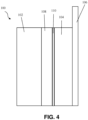
FIG. 4 . depicts a simplified schematic of an electrochemical cell including the composite electrolyte structure ofFIG. 1 in a second arrangement; and -
FIGS. 5-8 depict different processes to form variants of the composite electrolyte structure ofFIG. 1 . - For the purpose of promoting an understanding of the principles of the disclosure, reference will now be made to the embodiments illustrated in the drawings and described in the following written specification.
-
FIGS. 1 and 2 depict a ceramic-polymer composite electrolyte 20 in the form of a thin, disk-shaped separator ormembrane 22 in accordance with one embodiment. Thecomposite electrolyte 20 includes at least one ion-conducting inorganic phase 24 (hereinafter the "primary inorganic phase") and at least one non-conducting organic phase 26 (hereinafter the "primary organic phase"). The primaryorganic phase 26 is a carbon-containing phase and is not an ionic conductor. This non-conducting attribute enables the primaryorganic phase 26 to direct the majority of the ionic current that traverses thecomposite electrolyte 20 through the primaryinorganic phase 24. Thecomposite electrolyte 20 in some embodiments includes one or more additional non-conducting inorganic phases (not shown) on one or more surfaces of the primaryinorganic phase 24. - The primary
inorganic phase 24 in the embodiment shown is composed of particles orstructures 28 that traverse the entire thickness (t) of themembrane 22. The particles orstructures 28 in some embodiments are amorphous, such as in a Li-ion conducting glass. In other embodiments, the particles orstructures 28 are single-crystal particles with few or no grain boundaries per particle such that that the thickness (t) of thecomposite electrolyte 22 is the same order as the grain size in the primaryinorganic phase 24. The particles orstructures 28 in yet further embodiments are grown or sintered superstructures, such as nanowires or polycrystalline particles. The arrangement of theparticles 28 in thecomposite electrolyte 20 ensures that substantially everyparticle 28 has a first exposedsurface portion 30 on afirst side 32 of theelectrolyte 20 and a second exposedsurface portion 34 on a second side 36 of theelectrolyte 20. The first exposedsurface portions 30 and the second exposedsurface portions 34 of theparticles 28 are generally opposed to another on theopposite sides 32, 36 of theelectrolyte 20. - As best shown in
FIG. 2 , the primaryorganic phase 26 contacts theparticles 28 of the primaryinorganic phase 24 alongrespective interfaces 38 throughout themembrane 22. Since the primaryinorganic phase 24 traverses the entire thickness (t) of thecomposite electrolyte 20, the ionic current traverses very few inorganic-organic interfaces and sintering of the composite material after assembly is substantially minimized if not eliminated entirely. This feature of thecomposite electrolyte 20 minimizes the effect of interfacial resistance between media. Additionally, modifications can further improve the interfacial resistance between thecomposite electrolyte 20 and other parts of a battery cell that incorporates the composite electrolyte, such as other electrolytes, cathode or anode materials, and the like. - The
interfaces 38 between the primaryinorganic phase 24 and the primaryorganic phase 26 are engineered to possess strong adhesion characteristics. An unbroken chain of ionic bonds and/or covalent bonds is formed at the interfaces to promote strong adhesion therebetween. As used herein, an "unbroken chain" of one or more of ionic bonds and covalent bonds means that the number of actual bonds along the interface between the inorganic phase and the organic phase corresponds substantially with the number of possible bonds at the interface. In other words, the interface is configured to maximize the ionic and/or covalent bonds between the inorganic and organic phases at the respective interfaces such that there are virtually no discontinuities in bonding along the interfaces. In other embodiments, one or more of adhesion promotors and other surface modification agents are used to promote strong adhesion between the primaryinorganic phase 24 and the primaryorganic phase 26. In the resultingcomposite electrolyte 20 depicted inFIGS. 1 and 2 , the primaryinorganic phase 24 confers ionic conductivity on themembrane 22 and the primaryorganic phase 26 confers mechanical cohesion and flexibility on themembrane 22. - The
interfaces 38 between the primaryinorganic phase 24 and the primaryorganic phase 26 are configured with a variety of features that promote the strong bonding between theprimary phases particles 28 of the primaryinorganic phase 24 are functionalized and then subjected to a blending process in order to promote strong bonding with the primary organic phase 26 (e.g.,process 500 described with reference toFIG. 5 ). In other embodiments, theparticles 28 of the primaryinorganic phase 24 are subjected to a deposition process, an annealing process, a coating process, and a grouping/arranging process, and then subjected to another coating process in order to promote strong bonding with the primary organic phase 26 (e.g.,process 600 described with reference toFIG. 6 ). In yet other embodiments, theparticles 28 of the primaryinorganic phase 24 are subjected to a deposition process and a reaction process or a grafting process, and then subjected to a blending process in order to promote strong bonding with the primary organic phase 26 (e.g.,process 700 described with reference toFIG. 7 ). In still further embodiments, theparticles 28 of the primaryinorganic phase 24 are subjected to a coating process and a grafting process, and then a blade-casting process in order to promote strong bonding with the primary organic phase 26 (e.g.,process 800 described with reference toFIG. 8 ). -
FIG. 3 depicts anelectrochemical cell 100. Theelectrochemical cell 100 includes ananode 102, acathode 104 with an aluminum ("Al")current collector 106, aseparator 108, and acomposite electrolyte structure 110. Theanode 102 in the embodiment shown includes lithium metal, a lithium alloy metal, or a mesh filled with lithium metal or lithium alloy metal. Theanode 102 is sized such that it has at least as much capacity as thecathode 104, and preferably at least 10% excess capacity. The Alcurrent collector 106 is typically less than 30 microns in width and preferably less than 15 microns. In some embodiments, the Alcurrent collector 106 has a surface treatment. - The
cathode 104 includes a mixture of at least an active material and a matrix configured to conduct the primary ions of relevance to thecell 100. The active material in various embodiments includes a sulfur or sulfur-containing material (e.g., PAN-S composite or Li2S); an air electrode; Li-insertion materials such as NCM, LiNi0.5Mn1.5O4, Li-rich layered oxides, LiCoO2, LiFePO4, LiMn2O4; Li-rich NCM, NCA, and other Li intercalation materials, or blends thereof; or any other active material or blend of materials that react with and/or insert Li cations and/or electrolyte anions. - The matrix in various embodiments includes Li-conducting liquid, gel, polymer, or other solid electrolyte. Solid electrolyte materials in the
cathode 104 may further include lithium conducting garnets, lithium conducting sulfides (e.g., Li2S-P2S5) or phosphates, Li3P, LIPON, Li-conducting polymer (e.g., polyethylene oxide (PEO) or polycaprolactone (PCL)), Li-conducting metal-organic frameworks, Li3N, Li3P, thio-LISiCONs, Li-conducting NaSICONs, Li10GeP2S12, lithium polysulfidophosphates, or other solid Li-conducting material. Other materials in thecathode 104 may include electronically conductive additives such as carbon black, binder material, metal salts, plasticizers, fillers such as SiO2, or the like. The cathode materials are selected to allow sufficient electrolyte-cathode interfacial area for a desired design. Thecathode 104 may be greater than 1 micron in thickness, preferably greater than 10 microns, and more preferably greater than 40 microns. In one embodiment, the composition of thecathode 104 includes approximately 60 to 85 weight percent active material, approximately 3 to 10 weight percent carbon additive, and 15 to 35 weight percent catholyte. - Although the
cell 100 in the embodiment ofFIG. 3 is shown with oneseparator 108 and onecomposite electrolyte structure 110, thecell 100 in different embodiments can omit theseparator 108 or include more than onecomposite electrolyte structure 110. Thecomposite electrolyte structure 110 can have different positions relative to theanode 102 and thecathode 104 in different embodiments of thecell 100. For example,FIG. 3 depicts thecell 100 with thecomposite electrolyte structure 110 positioned between theseparator 108 and theanode 102.FIG. 4 depicts another embodiment of thecell 100 in which thecomposite electrolyte structure 110 is positioned between theseparator 108 and thecathode 104. In yet another embodiment (not shown), a firstcomposite electrolyte structure 110 is positioned between theseparator 108 and theanode 102 and a secondcomposite electrolyte structure 110 is positioned between theseparator 108 and thecathode 104. - The
anode 102 in some embodiments additionally or alternatively includes a composite electrode with a mixture of active material (e.g. Li, Li4Ti5O12, Si or intermetallic compounds), an ionically conductive matrix (e.g., solid polymer electrolyte, liquid electrolytes, ceramic electrolytes (e.g., nanowires), solid polyelectrolytes, or combinations thereof), and electronically conductive additives (e.g., carbon black). Theanode 102 in these embodiments can also include an anode current collector (e.g. Cu-foil with or without surface treatment). - The
anode 102 in further embodiments additionally or alternatively includes a matrix that conducts the primary ions of relevance to thecell 100. This matrix could include liquid or gel electrolytes, polymeric electrolytes such as polyethylene oxide (PEO), or ceramic or glassy sulfidic or oxidic ion conductors, or combinations. The matrix could further include binder(s), metal salts, plasticizers, fillers such as SiO2, or the like. The matrix may also contain carbon configured to provide electrical conductivity. The materials in the matrix on the anode side need not be identical to the material in the cathode side. - The
anode 102 in still further embodiments additionally or alternatively includes a graphitic Li-ion battery anode with or without modifications. Theanode 102 in yet still further embodiments additionally or alternatively includes Na or Mg metal or suitable intercalation compounds for Na or Mg metal ions. - The composite electrolyte structure 1 10 in various embodiments comprises the
composite electrolyte 20 ofFIG. 1 and any variants thereof formed by theprocesses FIGS. 5-8 , a ceramic thin layer prepared as by sputtering (e.g. LiPON), a "free standing" ceramic or glass ceramic layer (e.g. LATP), a polymer-ceramic composite in which the organic phase also conducts ions, and a polymer or gel including PS-block-PEO. The requirements of the composite electrolyte structure 1 10 depend in part on whether thecomposite electrolyte structure 110 contacts theanode 102 or thecathode 104 in a cell. In embodiments in which thecomposite electrolyte structure 110 directly contacts a Li anode (FIG. 3 ), thecomposite electrolyte structure 110 must be stable against, or form a stable solid electrolyte interphase (SEI) against, Li metal. Thecomposite electrolyte structure 110 must also function to suppress lithium dendrites or be resistant to Li dendrite penetration at current densities of at least 0.1mA/cm2 when thecomposite electrolyte structure 110 directly contacts a Li anode. -
FIGS. 5-8 depict different processes to form variants of thecomposite electrolyte structure 20 ofFIG. 1 .FIG. 5 illustrates afirst process 500 to form a first variant of the ceramic-polymer composite electrolyte 20 ofFIG. 1 . Initially, a polycrystalline Li-ionic conducting material, such as lithium lanthanum titanium oxide ("LLTO"), is synthesized with an average particle size of 6 microns (block 502). These particles are then functionalized with organophosphonic acids or phosphonate esters such as 1-decylphosphonic acid or diethyl undec-10-enyl phosphonate, for example, as per Ruiterkamp, G. J. et al, "Surface functionalization of titanium dioxide nanoparticles with alkanephosphonic acids for transparent nanocomposites", Journal of Nanoparticle Research, 13 (2011) 2779 (block 504). The functionalized particles are then blended with polyethylene, either pure or containing small amounts of initiators, and melt extruded to form a thin film with average thickness of 20 microns (block 506). In some instances, pressing is required to thin or densify the film (block 508). The film is then briefly etched, for example with oxygen plasma or UV-ozone, to remove residual organic material from the surfaces of the LLTO (block 510). -
FIG. 6 illustrates asecond process 600 to form a second variant of the ceramic-polymer electrolyte 20 ofFIG. 1 . In thesecond process 600, single crystals of lithium lanthanum zirconium oxide ("LLZO") are grown with an average crystal size of 20 microns (block 602). These particles are placed in a fluidized bed reactor and 100 nm of amorphous silicon dioxide ("SiO2") is deposited by a vapor-phase process, such as sputtering, onto the surface of the LLZO (block 604). After deposition, the particles are briefly annealed to homogenize the interface (block 606). The particles are then coated with 3-methacryloxypropyl trimethoxysilane via hydrolysis (block 608). The coated particles are then arranged in a single layer via contact with a surface coated in a water-soluble adhesive (block 610). The surface is then coated with a layer of ultraviolet (UV)-curable acrylate monomer and the entire assembly is UV cured (block 612). The water soluble adhesive is then removed (block 614). In some instances, the remaining film is briefly etched, for example with reactive-ion etching (RIE) or hydrogen fluoride (HF) etching combined with oxygen plasma or UV-ozone, to remove residual organic material and silica, thereby exposing the surfaces of the LLZO (block 616). -
FIG. 7 illustrates athird process 700 to form a third variant of the ceramic-polymer electrolyte 20 ofFIG. 1 . In thethird process 700, particles of amorphous 70/30 mol% Li2S-P2S5 are prepared with an average particle size of 10 microns (block 702). These particles are placed in a fluidized bed reactor and 200 nm of SiO2 is deposited by a vapor-phase process, such as sputtering, onto the surface of the Li2S-P2S5 (block 704). The particles are then reacted with a trimethoxysilane-substituted polystyrene or sulfonate-substituted polystyrene in an anhydrous liquid phase or by polystyrene grafting (block 706). The reacted particles are then blended in an appropriate ratio with a polystyrene solution and cast out to form a film with an average thickness of 20 microns (block 708). In some instances, pressing is required to thin or densify the film (block 710). The film is then etched lightly, for example by RIE, to remove excess polymer and SiO2, thereby exposing the sulfide surface on both sides of the thin film (block 712). -
FIG. 8 illustrates afourth process 800 to form a fourth variant of the ceramic-polymer electrolyte 20 ofFIG. 1 . In thefourth process 800, particles of lithium aluminum titanium silicon phosphate ("LATSP"), a Li-conducting glass ceramic ("LICGC"), are prepared with an average particle size of 12 microns (block 802). These particles are wet-coated with SiO2 via a typical sol-gel process (block 804). A polysiloxane with trichloro- or trimethoxy-silane pendant groups is grafted onto the SiO2 coated surface of the particles via hydrolysis (block 806). The composite is then blade cast into a film with an average dried thickness of 12 microns (block 808). In some instances, pressing is required to thin or densify the film (block 810). The film is then etched lightly, for example by RIE, to remove excess polymer and SiO2, thereby exposing the LATSP surface on both sides of the thin film (block 812). - The composite electrolyte disclosed herein as well as batteries and devices which include the composite electrolyte can be embodied in a number of different types and configurations.
- The composite electrolyte contains at least one ion-conducting inorganic phase and at least one non-conducting organic phase. The primary inorganic ion-conducting phase is composed of particles or structures that traverse the entire thickness of the electrolyte, and the interfaces between different materials in the composite membrane possess strong adhesion characteristics.
- The composite electrolyte may form a membrane that possesses an average ionic conductivity of at least 1E-5 S/cm, or area-specific resistance below 50 ohm-cm2 (preferably < 10 ohm-cm2).
- The strong adhesion at the interfaces between the different materials in the composite electrolyte is achieved via use of an unbroken chain of ionic or covalent bonds.
- The strong adhesion at the interfaces between the different materials in the composite electrolyte is achieved via adhesion promoters or other surface modification agents.
- The composite electrolyte may be stable against, or may form a stable solid electrolyte interface (SEI) against, Li metal.
- The composite electrolyte may form a free-standing, flexible film.
- The composite electrolyte may prevent or hinder passage of solvents or salts.
- The composite electrolyte may have a transference number t+ of greater than 0.8.
- The composite electrolyte may be resistant to Li dendrite penetration at current densities of at least 0.1 mA/cm2.
- The battery contains a composite electrolyte with at least one ion-conducting inorganic phase and at least one non-conducting organic phase. The primary inorganic ion-conducting phase is composed of particles or structures that traverse the entire thickness of the electrolyte, and the interfaces between different materials in the composite membrane possess strong adhesion characteristics.
- The composite electrolyte may function to suppress lithium dendrites.
- The composite electrolyte may function to isolate otherwise solvents, salts, or other mobile materials on one or more of the anode side and the cathode side of the cell.
- The composite electrolyte may function to modulate salt concentration gradients in liquid, gel, or polymeric batteries, thereby enabling improved rate capability.
Claims (8)
- A composite electrolyte structure, comprising:a first side and a second side defining a thickness;a non-conducting organic phase portion extending from the first side to the second side; anda plurality of ion-conducting inorganic phase structures dispersed throughout the non-conducting organic phase portion, each of the plurality of ion-conducting inorganic phase structures spanning the thickness such that a first portion of each of the plurality of ion-conducting inorganic phase structures is exposed on the first side and a second portion of each of the plurality of ion-conducting inorganic phase structures is exposed on the second side, each of the plurality of ion-conducting inorganic phase structures defining a respective interface with the non-conducting organic phase portion, wherein each of the respective interfaces includes an unbroken chain of at least one of ionic bonds and covalent bonds so as to firmly adhere the non-conducting organic phase portion to each of the plurality of ion-conducting inorganic phase structures,wherein each of the plurality of ion-conducting inorganic phase structures is formed from a monocrystalline material, the structures each including a first layer of a first adhesion promoter disposed on a surface of the structure and a second layer of a second adhesion promoter disposed on the first layer, orwherein each of the plurality of ion-conducting inorganic phase structures is formed from an amorphous material, the structures each including a first layer of a first adhesion promoter disposed on a surface of the structure and a second adhesion promoter reacted with the first layer, orwherein each of the plurality of ion-conducting inorganic phase structures is formed from a glass ceramic material, the structures each including a first layer of a first adhesion promoter disposed on a surface of the structure and a second adhesion promoter grafted on the first layer.
- The composite electrolyte structure of claim 1, wherein each of the plurality of ion-conducting inorganic phase structures is formed from a monocrystalline material, the structures each including a first layer of a first adhesion promoter disposed on a surface of the structure and a second layer of a second adhesion promoter disposed on the first layer, and wherein:the monocrystalline material is lithium lanthanum zirconium oxide,the first adhesion promoter is silicon dioxide,the second adhesion promoter is 3-methacryloxypropyl trimethoxysilane, andthe non-conducting organic phase portion is ultraviolet-curable acrylate monomer.
- The composite electrolyte structure of claim 1, wherein each of the plurality of ion-conducting inorganic phase structures is formed from an amorphous material, the structures each including a first layer of a first adhesion promoter disposed on a surface of the structure and a second adhesion promoter reacted with the first layer, and wherein:the amorphous material is Li2S-P2S5 in a ratio of 70/30 mol%,the first adhesion promoter is silicon dioxide,the second adhesion promoter is one of a trimethoxysilane-substituted polystyrene or a sulfonate-substituted polystyrene, andthe non-conducting organic phase portion is polystyrene.
- The composite electrolyte structure of claim 1, wherein each of the plurality of ion-conducting inorganic phase structures is formed from a glass ceramic material, the structures each including a first layer of a first adhesion promoter disposed on a surface of the structure and a second adhesion promoter grafted on the first layer, and wherein:the glass ceramic material is lithium aluminum titanium silicon phosphate,the first adhesion promoter is silicon dioxide, andthe second adhesion promoter is a polysiloxane with one of trichloro-silane pendant groups or trimethoxy-silane pendant groups.
- A battery cell, comprising:a positive electrode;a negative electrode; andat least one thin-film composite electrolyte structure disposed between the positive electrode and the negative electrode, the thin film composite electrolyte structure being a composite electrolyte structure of any one of claims 1 to 4.
- The battery cell of claim 5, further comprising a separator disposed between the positive electrode and the negative electrode, the electrolyte structure disposed between the separator and the negative electrode.
- The battery cell of claim 5, further comprising a separator disposed between the positive electrode and the negative electrode, the electrolyte structure disposed between the separator and the positive electrode.
- The battery cell of claim 5, wherein the battery cell is a two-compartment battery cell with anolyte in a first compartment and catholyte in a second compartment, the electrolyte structure configured to separate the anolyte and the catholyte from one another.
Applications Claiming Priority (2)
| Application Number | Priority Date | Filing Date | Title |
|---|---|---|---|
| US201762571348P | 2017-10-12 | 2017-10-12 | |
| PCT/EP2018/077034 WO2019072684A1 (en) | 2017-10-12 | 2018-10-04 | Ceramic-polymer composite single ion conducting thin film electrolyte |
Publications (2)
| Publication Number | Publication Date |
|---|---|
| EP3695452A1 EP3695452A1 (en) | 2020-08-19 |
| EP3695452B1 true EP3695452B1 (en) | 2024-12-11 |
Family
ID=63914993
Family Applications (1)
| Application Number | Title | Priority Date | Filing Date |
|---|---|---|---|
| EP18789332.6A Active EP3695452B1 (en) | 2017-10-12 | 2018-10-04 | Ceramic-polymer composite single ion conducting thin film electrolyte |
Country Status (4)
| Country | Link |
|---|---|
| US (1) | US11456481B2 (en) |
| EP (1) | EP3695452B1 (en) |
| CN (1) | CN111183543B (en) |
| WO (1) | WO2019072684A1 (en) |
Families Citing this family (2)
| Publication number | Priority date | Publication date | Assignee | Title |
|---|---|---|---|---|
| FR3112244B1 (en) * | 2020-07-06 | 2022-08-12 | Blue Solutions | Hybrid Separating Membrane for Battery |
| CN114597591B (en) * | 2022-05-10 | 2022-08-12 | 四川新能源汽车创新中心有限公司 | Lithium battery separator and preparation method and application thereof |
Family Cites Families (8)
| Publication number | Priority date | Publication date | Assignee | Title |
|---|---|---|---|---|
| WO2007066967A1 (en) * | 2005-12-06 | 2007-06-14 | Lg Chem, Ltd. | Organic/ inorganic composite separator having morphology gradient, manufacturing method thereof and electrochemical device containing the same |
| JP2009051872A (en) * | 2007-08-23 | 2009-03-12 | Toyota Motor Corp | Porous membrane manufacturing method, polymer electrolyte manufacturing method, porous membrane, polymer electrolyte membrane, and solid polymer fuel cell |
| US9893337B2 (en) * | 2008-02-13 | 2018-02-13 | Seeo, Inc. | Multi-phase electrolyte lithium batteries |
| US9502729B2 (en) | 2012-08-29 | 2016-11-22 | Corning Incorporated | Ion-conducting composite electrolyte comprising path-engineered particles |
| US9478809B2 (en) | 2013-07-16 | 2016-10-25 | Ford Global Technologies, Llc | Flexible composite solid polymer electrochemical membrane |
| DE102013226064A1 (en) * | 2013-12-16 | 2015-06-18 | Robert Bosch Gmbh | Method for producing a functional layer for a lithium cell |
| US9520627B2 (en) * | 2014-03-06 | 2016-12-13 | International Business Machines Corporation | Ion conducting hybrid membranes |
| DE102016208532A1 (en) * | 2016-05-18 | 2017-11-23 | Schott Ag | A lithium ion conductive composite comprising at least one polymer and lithium ion conductive particles |
-
2018
- 2018-10-04 US US16/645,366 patent/US11456481B2/en active Active
- 2018-10-04 CN CN201880066190.3A patent/CN111183543B/en active Active
- 2018-10-04 EP EP18789332.6A patent/EP3695452B1/en active Active
- 2018-10-04 WO PCT/EP2018/077034 patent/WO2019072684A1/en not_active Ceased
Also Published As
| Publication number | Publication date |
|---|---|
| US11456481B2 (en) | 2022-09-27 |
| EP3695452A1 (en) | 2020-08-19 |
| US20210119244A1 (en) | 2021-04-22 |
| WO2019072684A1 (en) | 2019-04-18 |
| CN111183543B (en) | 2023-08-18 |
| CN111183543A (en) | 2020-05-19 |
Similar Documents
| Publication | Publication Date | Title |
|---|---|---|
| US20200335818A1 (en) | Porous Ceramic Fibers for Electrolyte Support and Processing | |
| JP7102556B2 (en) | Solid electrolyte membrane and all-solid-state battery containing it | |
| US20200067128A1 (en) | Hybrid and solid-state battery architectures with high loading and methods of manufacture thereof | |
| US7514180B2 (en) | Battery with molten salt electrolyte and protected lithium-based negative electrode material | |
| CN111384399B (en) | Protective coating for lithium metal electrodes | |
| JP7335024B2 (en) | Lithium secondary battery | |
| US9249522B2 (en) | Electrophoretic deposition of thin film batteries | |
| JP7263551B2 (en) | Electrolyte membrane for all-solid-state battery and all-solid-state battery including the same | |
| WO2020041767A1 (en) | Hybrid and solid-state battery architectures with high loading and methods of manufacture thereof | |
| CN114008851A (en) | Electrically coupled electrodes and related articles and methods | |
| CN110225887B (en) | Method of preparing positive active material for secondary battery, positive active material prepared thereby, and lithium secondary battery comprising same | |
| CN105849964A (en) | Li-ion battery with coated electrolyte | |
| CN112602208B (en) | Electrode for all-solid-state battery and method of manufacturing electrode assembly including same | |
| CN110235287B (en) | Interconnector functionalized cathodes for solid-state batteries | |
| KR20240001150A (en) | Method and structure for transferring carrier ions from auxiliary electrode | |
| JP7222096B2 (en) | Electrolyte membrane for all-solid-state battery and all-solid-state battery including the same | |
| CN114784372A (en) | Preparation method of composite solid electrolyte | |
| KR102413379B1 (en) | A solid electrolyte layer and an all-solid-state battery comprising the same | |
| US11456481B2 (en) | Ceramic-polymer composite single ion conducting thin film electrolyte | |
| KR20200050627A (en) | Composite Electrode Including Gel-Type Polymer Electrolyte for All-Solid-State Battery, Method Of Manufacturing The Same, And All-Solid-State Lithium Battery Comprising The Same | |
| KR102810362B1 (en) | A electrolyte membrane for all solid-state battery and an all solid-state battery comprising the same | |
| CN105934844A (en) | Solid state battery with offset geometry | |
| KR102802158B1 (en) | An electrode for all solid-state battery and an all solid-state battery comprising the same | |
| KR20250003371A (en) | Anode for rechargeable zinc battery using amphiphilic block copolymer and rechargeable zinc battery including the same | |
| KR20230064084A (en) | Solid Electrolyte having core-shell structure and manufacturing method the Same |
Legal Events
| Date | Code | Title | Description |
|---|---|---|---|
| STAA | Information on the status of an ep patent application or granted ep patent |
Free format text: STATUS: UNKNOWN |
|
| STAA | Information on the status of an ep patent application or granted ep patent |
Free format text: STATUS: THE INTERNATIONAL PUBLICATION HAS BEEN MADE |
|
| PUAI | Public reference made under article 153(3) epc to a published international application that has entered the european phase |
Free format text: ORIGINAL CODE: 0009012 |
|
| STAA | Information on the status of an ep patent application or granted ep patent |
Free format text: STATUS: REQUEST FOR EXAMINATION WAS MADE |
|
| 17P | Request for examination filed |
Effective date: 20200512 |
|
| AK | Designated contracting states |
Kind code of ref document: A1 Designated state(s): AL AT BE BG CH CY CZ DE DK EE ES FI FR GB GR HR HU IE IS IT LI LT LU LV MC MK MT NL NO PL PT RO RS SE SI SK SM TR |
|
| AX | Request for extension of the european patent |
Extension state: BA ME |
|
| DAV | Request for validation of the european patent (deleted) | ||
| DAX | Request for extension of the european patent (deleted) | ||
| STAA | Information on the status of an ep patent application or granted ep patent |
Free format text: STATUS: EXAMINATION IS IN PROGRESS |
|
| 17Q | First examination report despatched |
Effective date: 20230808 |
|
| REG | Reference to a national code |
Ref country code: DE Ref legal event code: R079 Free format text: PREVIOUS MAIN CLASS: H01M0010052000 Ipc: H01M0010056000 Ref country code: DE Ref legal event code: R079 Ref document number: 602018077531 Country of ref document: DE Free format text: PREVIOUS MAIN CLASS: H01M0010052000 Ipc: H01M0010056000 |
|
| GRAP | Despatch of communication of intention to grant a patent |
Free format text: ORIGINAL CODE: EPIDOSNIGR1 |
|
| STAA | Information on the status of an ep patent application or granted ep patent |
Free format text: STATUS: GRANT OF PATENT IS INTENDED |
|
| RIC1 | Information provided on ipc code assigned before grant |
Ipc: H01M 4/38 20060101ALI20240620BHEP Ipc: H01M 4/36 20060101ALI20240620BHEP Ipc: H01M 10/052 20100101ALI20240620BHEP Ipc: H01M 10/056 20100101AFI20240620BHEP |
|
| INTG | Intention to grant announced |
Effective date: 20240711 |
|
| GRAS | Grant fee paid |
Free format text: ORIGINAL CODE: EPIDOSNIGR3 |
|
| GRAA | (expected) grant |
Free format text: ORIGINAL CODE: 0009210 |
|
| STAA | Information on the status of an ep patent application or granted ep patent |
Free format text: STATUS: THE PATENT HAS BEEN GRANTED |
|
| AK | Designated contracting states |
Kind code of ref document: B1 Designated state(s): AL AT BE BG CH CY CZ DE DK EE ES FI FR GB GR HR HU IE IS IT LI LT LU LV MC MK MT NL NO PL PT RO RS SE SI SK SM TR |
|
| REG | Reference to a national code |
Ref country code: GB Ref legal event code: FG4D |
|
| REG | Reference to a national code |
Ref country code: CH Ref legal event code: EP |
|
| REG | Reference to a national code |
Ref country code: IE Ref legal event code: FG4D |
|
| REG | Reference to a national code |
Ref country code: DE Ref legal event code: R096 Ref document number: 602018077531 Country of ref document: DE |
|
| REG | Reference to a national code |
Ref country code: LT Ref legal event code: MG9D |
|
| PG25 | Lapsed in a contracting state [announced via postgrant information from national office to epo] |
Ref country code: HR Free format text: LAPSE BECAUSE OF FAILURE TO SUBMIT A TRANSLATION OF THE DESCRIPTION OR TO PAY THE FEE WITHIN THE PRESCRIBED TIME-LIMIT Effective date: 20241211 |
|
| PG25 | Lapsed in a contracting state [announced via postgrant information from national office to epo] |
Ref country code: FI Free format text: LAPSE BECAUSE OF FAILURE TO SUBMIT A TRANSLATION OF THE DESCRIPTION OR TO PAY THE FEE WITHIN THE PRESCRIBED TIME-LIMIT Effective date: 20241211 |
|
| PG25 | Lapsed in a contracting state [announced via postgrant information from national office to epo] |
Ref country code: BG Free format text: LAPSE BECAUSE OF FAILURE TO SUBMIT A TRANSLATION OF THE DESCRIPTION OR TO PAY THE FEE WITHIN THE PRESCRIBED TIME-LIMIT Effective date: 20241211 |
|
| REG | Reference to a national code |
Ref country code: NL Ref legal event code: MP Effective date: 20241211 |
|
| PG25 | Lapsed in a contracting state [announced via postgrant information from national office to epo] |
Ref country code: ES Free format text: LAPSE BECAUSE OF FAILURE TO SUBMIT A TRANSLATION OF THE DESCRIPTION OR TO PAY THE FEE WITHIN THE PRESCRIBED TIME-LIMIT Effective date: 20241211 |
|
| PG25 | Lapsed in a contracting state [announced via postgrant information from national office to epo] |
Ref country code: NO Free format text: LAPSE BECAUSE OF FAILURE TO SUBMIT A TRANSLATION OF THE DESCRIPTION OR TO PAY THE FEE WITHIN THE PRESCRIBED TIME-LIMIT Effective date: 20250311 |
|
| PG25 | Lapsed in a contracting state [announced via postgrant information from national office to epo] |
Ref country code: LV Free format text: LAPSE BECAUSE OF FAILURE TO SUBMIT A TRANSLATION OF THE DESCRIPTION OR TO PAY THE FEE WITHIN THE PRESCRIBED TIME-LIMIT Effective date: 20241211 Ref country code: GR Free format text: LAPSE BECAUSE OF FAILURE TO SUBMIT A TRANSLATION OF THE DESCRIPTION OR TO PAY THE FEE WITHIN THE PRESCRIBED TIME-LIMIT Effective date: 20250312 |
|
| PG25 | Lapsed in a contracting state [announced via postgrant information from national office to epo] |
Ref country code: RS Free format text: LAPSE BECAUSE OF FAILURE TO SUBMIT A TRANSLATION OF THE DESCRIPTION OR TO PAY THE FEE WITHIN THE PRESCRIBED TIME-LIMIT Effective date: 20250311 |
|
| PG25 | Lapsed in a contracting state [announced via postgrant information from national office to epo] |
Ref country code: NL Free format text: LAPSE BECAUSE OF FAILURE TO SUBMIT A TRANSLATION OF THE DESCRIPTION OR TO PAY THE FEE WITHIN THE PRESCRIBED TIME-LIMIT Effective date: 20241211 |
|
| REG | Reference to a national code |
Ref country code: AT Ref legal event code: MK05 Ref document number: 1751107 Country of ref document: AT Kind code of ref document: T Effective date: 20241211 |
|
| PG25 | Lapsed in a contracting state [announced via postgrant information from national office to epo] |
Ref country code: SM Free format text: LAPSE BECAUSE OF FAILURE TO SUBMIT A TRANSLATION OF THE DESCRIPTION OR TO PAY THE FEE WITHIN THE PRESCRIBED TIME-LIMIT Effective date: 20241211 |
|
| PG25 | Lapsed in a contracting state [announced via postgrant information from national office to epo] |
Ref country code: PL Free format text: LAPSE BECAUSE OF FAILURE TO SUBMIT A TRANSLATION OF THE DESCRIPTION OR TO PAY THE FEE WITHIN THE PRESCRIBED TIME-LIMIT Effective date: 20241211 |
|
| PG25 | Lapsed in a contracting state [announced via postgrant information from national office to epo] |
Ref country code: IS Free format text: LAPSE BECAUSE OF FAILURE TO SUBMIT A TRANSLATION OF THE DESCRIPTION OR TO PAY THE FEE WITHIN THE PRESCRIBED TIME-LIMIT Effective date: 20250411 |
|
| PG25 | Lapsed in a contracting state [announced via postgrant information from national office to epo] |
Ref country code: PT Free format text: LAPSE BECAUSE OF FAILURE TO SUBMIT A TRANSLATION OF THE DESCRIPTION OR TO PAY THE FEE WITHIN THE PRESCRIBED TIME-LIMIT Effective date: 20250411 |
|
| PG25 | Lapsed in a contracting state [announced via postgrant information from national office to epo] |
Ref country code: EE Free format text: LAPSE BECAUSE OF FAILURE TO SUBMIT A TRANSLATION OF THE DESCRIPTION OR TO PAY THE FEE WITHIN THE PRESCRIBED TIME-LIMIT Effective date: 20241211 |
|
| PG25 | Lapsed in a contracting state [announced via postgrant information from national office to epo] |
Ref country code: RO Free format text: LAPSE BECAUSE OF FAILURE TO SUBMIT A TRANSLATION OF THE DESCRIPTION OR TO PAY THE FEE WITHIN THE PRESCRIBED TIME-LIMIT Effective date: 20241211 Ref country code: AT Free format text: LAPSE BECAUSE OF FAILURE TO SUBMIT A TRANSLATION OF THE DESCRIPTION OR TO PAY THE FEE WITHIN THE PRESCRIBED TIME-LIMIT Effective date: 20241211 |
|
| PG25 | Lapsed in a contracting state [announced via postgrant information from national office to epo] |
Ref country code: SK Free format text: LAPSE BECAUSE OF FAILURE TO SUBMIT A TRANSLATION OF THE DESCRIPTION OR TO PAY THE FEE WITHIN THE PRESCRIBED TIME-LIMIT Effective date: 20241211 |
|
| PG25 | Lapsed in a contracting state [announced via postgrant information from national office to epo] |
Ref country code: CZ Free format text: LAPSE BECAUSE OF FAILURE TO SUBMIT A TRANSLATION OF THE DESCRIPTION OR TO PAY THE FEE WITHIN THE PRESCRIBED TIME-LIMIT Effective date: 20241211 |
|
| PG25 | Lapsed in a contracting state [announced via postgrant information from national office to epo] |
Ref country code: IT Free format text: LAPSE BECAUSE OF FAILURE TO SUBMIT A TRANSLATION OF THE DESCRIPTION OR TO PAY THE FEE WITHIN THE PRESCRIBED TIME-LIMIT Effective date: 20241211 |
|
| PG25 | Lapsed in a contracting state [announced via postgrant information from national office to epo] |
Ref country code: SE Free format text: LAPSE BECAUSE OF FAILURE TO SUBMIT A TRANSLATION OF THE DESCRIPTION OR TO PAY THE FEE WITHIN THE PRESCRIBED TIME-LIMIT Effective date: 20241211 |
|
| REG | Reference to a national code |
Ref country code: DE Ref legal event code: R097 Ref document number: 602018077531 Country of ref document: DE |
|
| PG25 | Lapsed in a contracting state [announced via postgrant information from national office to epo] |
Ref country code: DK Free format text: LAPSE BECAUSE OF FAILURE TO SUBMIT A TRANSLATION OF THE DESCRIPTION OR TO PAY THE FEE WITHIN THE PRESCRIBED TIME-LIMIT Effective date: 20241211 |
|
| PLBE | No opposition filed within time limit |
Free format text: ORIGINAL CODE: 0009261 |
|
| STAA | Information on the status of an ep patent application or granted ep patent |
Free format text: STATUS: NO OPPOSITION FILED WITHIN TIME LIMIT |
|
| 26N | No opposition filed |
Effective date: 20250912 |
|
| PGFP | Annual fee paid to national office [announced via postgrant information from national office to epo] |
Ref country code: DE Payment date: 20251209 Year of fee payment: 8 |
|
| PGFP | Annual fee paid to national office [announced via postgrant information from national office to epo] |
Ref country code: GB Payment date: 20251024 Year of fee payment: 8 |
|
| PGFP | Annual fee paid to national office [announced via postgrant information from national office to epo] |
Ref country code: FR Payment date: 20251022 Year of fee payment: 8 |