EP3694731B1 - Suspension assembly for a vehicle axle - Google Patents
Suspension assembly for a vehicle axle Download PDFInfo
- Publication number
- EP3694731B1 EP3694731B1 EP18799839.8A EP18799839A EP3694731B1 EP 3694731 B1 EP3694731 B1 EP 3694731B1 EP 18799839 A EP18799839 A EP 18799839A EP 3694731 B1 EP3694731 B1 EP 3694731B1
- Authority
- EP
- European Patent Office
- Prior art keywords
- suspension assembly
- guides
- main
- vehicle
- support structure
- Prior art date
- Legal status (The legal status is an assumption and is not a legal conclusion. Google has not performed a legal analysis and makes no representation as to the accuracy of the status listed.)
- Active
Links
Images




Classifications
-
- B—PERFORMING OPERATIONS; TRANSPORTING
- B60—VEHICLES IN GENERAL
- B60G—VEHICLE SUSPENSION ARRANGEMENTS
- B60G9/00—Resilient suspensions of a rigid axle or axle housing for two or more wheels
- B60G9/02—Resilient suspensions of a rigid axle or axle housing for two or more wheels the axle or housing being pivotally mounted on the vehicle, e.g. the pivotal axis being parallel to the longitudinal axis of the vehicle
- B60G9/027—Resilient suspensions of a rigid axle or axle housing for two or more wheels the axle or housing being pivotally mounted on the vehicle, e.g. the pivotal axis being parallel to the longitudinal axis of the vehicle the axle having either a triangular, a "T" or "U" shape and being directly articulated with the chassis only by its middle apex, e.g. De Dion suspension
-
- B—PERFORMING OPERATIONS; TRANSPORTING
- B60—VEHICLES IN GENERAL
- B60G—VEHICLE SUSPENSION ARRANGEMENTS
- B60G13/00—Resilient suspensions characterised by arrangement, location or type of vibration dampers
- B60G13/02—Resilient suspensions characterised by arrangement, location or type of vibration dampers having dampers dissipating energy, e.g. frictionally
- B60G13/06—Resilient suspensions characterised by arrangement, location or type of vibration dampers having dampers dissipating energy, e.g. frictionally of fluid type
- B60G13/08—Resilient suspensions characterised by arrangement, location or type of vibration dampers having dampers dissipating energy, e.g. frictionally of fluid type hydraulic
-
- B—PERFORMING OPERATIONS; TRANSPORTING
- B60—VEHICLES IN GENERAL
- B60G—VEHICLE SUSPENSION ARRANGEMENTS
- B60G2200/00—Indexing codes relating to suspension types
- B60G2200/30—Rigid axle suspensions
- B60G2200/32—Rigid axle suspensions pivoted
- B60G2200/324—Rigid axle suspensions pivoted with a single pivot point and a triangular "T" or "U"-shaped axle, e.g. DeDion arrangement
-
- B—PERFORMING OPERATIONS; TRANSPORTING
- B60—VEHICLES IN GENERAL
- B60G—VEHICLE SUSPENSION ARRANGEMENTS
- B60G2200/00—Indexing codes relating to suspension types
- B60G2200/30—Rigid axle suspensions
- B60G2200/34—Stabilising mechanisms, e.g. for lateral stability
-
- B—PERFORMING OPERATIONS; TRANSPORTING
- B60—VEHICLES IN GENERAL
- B60G—VEHICLE SUSPENSION ARRANGEMENTS
- B60G2200/00—Indexing codes relating to suspension types
- B60G2200/40—Indexing codes relating to the wheels in the suspensions
- B60G2200/422—Driving wheels or live axles
-
- B—PERFORMING OPERATIONS; TRANSPORTING
- B60—VEHICLES IN GENERAL
- B60G—VEHICLE SUSPENSION ARRANGEMENTS
- B60G2200/00—Indexing codes relating to suspension types
- B60G2200/40—Indexing codes relating to the wheels in the suspensions
- B60G2200/44—Indexing codes relating to the wheels in the suspensions steerable
-
- B—PERFORMING OPERATIONS; TRANSPORTING
- B60—VEHICLES IN GENERAL
- B60G—VEHICLE SUSPENSION ARRANGEMENTS
- B60G2204/00—Indexing codes related to suspensions per se or to auxiliary parts
- B60G2204/40—Auxiliary suspension parts; Adjustment of suspensions
- B60G2204/423—Rails, tubes, or the like, for guiding the movement of suspension elements
-
- B—PERFORMING OPERATIONS; TRANSPORTING
- B60—VEHICLES IN GENERAL
- B60G—VEHICLE SUSPENSION ARRANGEMENTS
- B60G2204/00—Indexing codes related to suspensions per se or to auxiliary parts
- B60G2204/40—Auxiliary suspension parts; Adjustment of suspensions
- B60G2204/45—Stops limiting travel
-
- B—PERFORMING OPERATIONS; TRANSPORTING
- B60—VEHICLES IN GENERAL
- B60G—VEHICLE SUSPENSION ARRANGEMENTS
- B60G2300/00—Indexing codes relating to the type of vehicle
- B60G2300/08—Agricultural vehicles
-
- B—PERFORMING OPERATIONS; TRANSPORTING
- B60—VEHICLES IN GENERAL
- B60G—VEHICLE SUSPENSION ARRANGEMENTS
- B60G2300/00—Indexing codes relating to the type of vehicle
- B60G2300/08—Agricultural vehicles
- B60G2300/082—Tractors
Definitions
- This invention relates to a suspension assembly for a vehicle axle, in particular an agricultural vehicle or other similar vehicle suitable for off-road use. More specifically, the invention relates to a suspension assembly for a front axle, wherein the axle as a whole can move in relation to a vehicle chassis.
- the axle is primarily supported on the chassis by means of the hydraulic cylinders of the suspension and of a support arm which can oscillate in relation to the vehicle chassis and in relation to which the axle can rotate about a longitudinal axis of the vehicle itself.
- the aforementioned hydraulic cylinders are intended, while substantially maintaining the axle in vertical untilted position, to make the vehicle pass from a lowered chassis position in relation to the terrain and the wheels, to a raised chassis position that allows the wheels to further tilt in relation to the terrain without coming into contact with any part of the chassis itself or with any eventual wheel cover. Therefore, the functions of the hydraulic cylinders that are described are those of absorbing or cancelling out the oscillations of the axle and/or of maintaining the axle in a constant central position (especially during use in the raised position).
- the axle being linked to the hydraulic cylinders that absorb oscillations, has a specific limited degree of mobility that makes it partially suitable for use in vehicles intended to be used off-road.
- axle is not very suitable for use on particularly irregular terrain due to the presence of the hydraulic cylinders that absorb oscillations.
- the technical problem which is at the basis of this invention is that of supplying a suspension assembly for a vehicle axle, in particular for agricultural vehicles or other similar vehicles, suitable for off-road use, which makes it possible to at least partially remedy one or more disadvantages mentioned above with reference to the prior art.
- the purpose of this invention is that of supplying a suspension assembly for a vehicle axle which allows for efficient mobility and control, but which, however, contemporaneously provides adequate sturdiness and protection from excessive axle oscillations and stress.
- a further purpose of this invention is that of supplying a suspension assembly for a vehicle axle that can best adapt to the irregularities of the terrain, maintaining the structural integrity of the vehicle itself unaltered while driving.
- the purpose of this invention is that of supplying a suspension assembly for a vehicle axle that has a structure that can easily be made and installed and that, at the same time, is reliable for use in vehicles intended for off-road use.
- the suspension assembly for a vehicle axle made according to this invention, comprising a support structure for an axle, a housing element for a driveshaft, the housing element being rotatably connected, about an axis that is perpendicular to the longitudinal axis of the vehicle, to a main chassis of the vehicle at one of its first extremities, the support structure being rotatably connected to the housing element about an axis that is substantially parallel to the longitudinal axis of the vehicle and being secured to the main chassis of the vehicle by of a pair of hydraulic cylinders and comprising a pair of main guides, which can be secured to the main chassis, and a rolling element which slides between the pair of main guides.
- the suspension assembly comprises a contact element, secured to the support structure and a pair of further guides, which can be fixed to the main chassis, with the contact element being located between said pair of further guides and operatively associated with the pair of further guides so as to come into contact with one of the further guides following a rotation about the rolling element, as described in US 6 299 188 B1 .
- the axle according to this invention allows for sufficient mobility for the wheels of the vehicle, therefore allowing it to proceed over rough terrain in an optimum manner, with a sturdy structure that protects the parts responsible for the movement of the axle in case of excessive motion or stress.
- a contact element associated with a further pair of linear guides with which the contact element comes into contact following an oscillation of the axle, allows for the limitation in an opportune manner of the rotational motion of the axle, whilst however permitting the vertical movement and oscillation. In this way, the structure is strengthened without compromising the mobility and control of the axle.
- the main guides and the further guides are straight and are, in use, substantially vertical.
- the rolling element and the contact element are both disc-shaped, preferably having the same diameter.
- the further guides have a distance between each other that is greater than the distance between the main guides.
- the further guides extend as extensions of the main guides.
- the suspension assembly can be made more compact, minimising the space it occupies.
- the contact element is located beneath the rolling element in relation to the rotational axis of the support structure.
- an optimal vertically-aligned arrangement of the axle and of the rolling and contact elements is achieved during configurations without inclination of the terrain (when the terrain is flat or with irregularities that are symmetrical with respect to the vertical axis of the axle).
- the suspension assembly further comprises at least one stop element which can be fixed to the main chassis and configured in such a manner that it comes into contact with the support structure following a vertical motion.
- the further guides are joined at one of their lower extremities by means of a reinforcing crossbar, increasing the stability and rigidity of the structure responsible for housing and securing the rolling element and the contact element, furthermore providing a further, lower contact element that limits the movement of the contact element, thus avoiding potentially excessive and potentially damaging motion.
- this feature is particularly advantageous if it is adopted in combination with the placement of the contact element beneath the rolling element as previously indicated.
- the rolling element and the contact element are located at an extremity which is opposite to the housing element.
- 100 indicates, as a whole, a suspension assembly for a vehicle axle, in particular an agricultural vehicle or other similar vehicle suitable for off-road use.
- the suspension assembly 100 comprises a support structure 1 for an axle and a housing element 2 for a driveshaft 10.
- the driveshaft 10 lies in a longitudinal plane of symmetry of the vehicle and it preferably has a development that is substantially parallel or inclined to the longitudinal axis of the vehicle.
- the driveshaft 10 advantageously comprises two shafts 10a, 10b connected to each other by means of a universal joint 10c.
- the housing element 2 is rotatably connected, about a transverse axis Y, perpendicular to the longitudinal axis of the aforementioned vehicle, to a main chassis 101 of the vehicle, at its first extremity 22.
- the first extremity 22 has a pair of arms, each one advantageously hinged about the aforementioned axis Y on a support element 11 connected to the main chassis 101.
- the support structure 1 is rotatably connected to the housing element 2 about a rotational axis X, which likewise lies in a longitudinal plane of symmetry of the vehicle and is substantially parallel or inclined to the driveshaft.
- the housing element 2 is rotatably connected to the support element 11 by means of a ball joint 12 in order to allow for the rotation about the axis X and the transverse axis that is perpendicular to it. This rotational motion will be illustrated in greater detail below.
- Figs. 2 , 4a and 5a show an axial XYZ triplet which represents the spatial orientation of the longitudinal axis X, of the perpendicular axis Y and of a vertical axis Z perpendicular to both.
- the support structure 1 is secured, according to an embodiment, to the main chassis 101 of the vehicle by means of a pair of hydraulic cylinders 3.
- the support structure 1 comprises, preferably, a pair of main guides 4, which can be fixed onto the main chassis 101 and a rolling element 5 which slides between the pair of main guides 4.
- the suspension assembly 100 comprises a contact element 6, secured to the support structure 1 and a pair of further guides 41, which can be fixed to the main chassis 101.
- the contact element 6 is operationally associated with the pair of further guides 41 in such a manner that it comes into contact with one of the further guides 41 following a rotation about the rolling element 5.
- the contact element 6 defines an end-of-travel position coming into contact with one of the further guides 41 and thus constraining the motion, at least in relation to one component of the perpendicular axis Y, of the suspension assembly 100 in relation to the main chassis 101 or, in other words, the rotation of the assembly 100 about the vertical axis Z.
- the main guides 4 and the further guides 41 are straight and, in use, are substantially vertical.
- a first inclination condition I of the support structure 1 in relation to the axial XYZ triplet and to the main guides 4 and the further guides 41 is shown.
- the rolling element 5 is secured between the pair of main guides 4, located in correspondence with the maximum upward vertical motion (which is to say, in the direction that corresponds to increasing values of Z) and rotated anticlockwise by a first angle ⁇ in relation to the vertical axis Z.
- the contact element 6 comes into contact with one of the further guides 41, thereby defining an end-of-travel position of the suspension assembly 100 in relation to at least one component of the perpendicular axis Y.
- the rolling element 5 and the contact element 6 are both disc-shaped.
- the further guides 41 have, preferably, a greater distance from one another than the main guides 4. According to the embodiment shown in the aforementioned figures, while the rolling element 5 translates in relation to the vertical axis Z and rotates in relation to the longitudinal axis X, this distance from one another of the further guides 41 allows the contact element 6 to translate both in relation to the vertical axis Z as well as in relation to the perpendicular axis Y and to rotate in relation to the longitudinal axis X.
- the further guides 41 define a boundary for the rotational-translational motion of the contact element 6 and therefore for the suspension assembly 100 secured to it.
- the further guides 41 extend as extensions of the main guides 4.
- each of the further guides 41 and of the main guides 4 is produced in a single piece as shown in Fig. 2 and profiled as needed.
- each individual part which is to say, each part comprising a main guide 4 extending into the further guide 41, includes a connection portion that is inclined in relation to the vertical axis Z and divergent from the axis Z as it moves away from the rolling element 5.
- the contact element 6 is located beneath the rolling element 5 in relation to the rotational axis X of the support structure 1.
- the rolling element 5 and the contact element 6 are aligned in relation to the vertical axis Z.
- the suspension assembly 100 further comprises at least one stop element 8 which can be fixed to the main chassis 101 and configured in such a manner that it comes into contact with the support structure 1 following a vertical motion.
- the suspension assembly 100 advantageously comprises two stop elements 8.
- the two stop elements 8 are symmetrically located in relation to the longitudinal axis X.
- a condition is shown wherein the suspension assembly 100 is in contact with both stop elements.
- the suspension assembly 100 preferably assumes a zero inclination in relation to the vertical axis Z.
- the further guides 41 are joined at one of their lower extremities 42 by means of a reinforcing crossbar 9.
- the reinforcing crossbar 9 is preferably located in a longitudinal position that is more advanced in relation to the contact element 6. In this manner, the contact element can also move to a position that is vertically below the crossbar 9.
- a second inclination condition II of the support structure 1 is shown, in relation to the axial XYZ triplet and to the main guides 4 and the further guides 41.
- the rolling element 5 is secured between the pair of main guides 4 and located in correspondence with the minimum downward vertical motion (which is to say, in the direction corresponding to decreasing values of Z) and rotated anticlockwise by a second angle ⁇ in relation to the vertical axis Z.
- the contact element 6 comes into contact with one of the further guides 41 and/or the reinforcing crossbar 9, thus determining an end-of-travel position of the suspension assembly 100, at least in relation to a component of the perpendicular axis Y and/or in relation to a component of the vertical axis Z.
- the rolling element 5 and the contact element 6 are located at an extremity opposite the housing element 2.
- the rolling element 5 and the contact element 6 are located on a side of the support structure that is substantially perpendicular to the longitudinal X axis of the vehicle.
- the housing element 2 is rotatably connected to the support structure 1 by means of a bearing 12 at the extremity 21 which is opposite to that connected to the support element 11.
- the first extremity 22 is C-shaped and each arm of the first extremity 22 is advantageously hinged on a respective location of the support element 11. This connection allows the housing element 2 to rotate about the axis Y.
- the rotational capability of the support structure 1 about the axis X is instead obtained by means of the bearing 12. It will therefore be appreciated that the rotational axis X substantially coincides with the shaft 10a, and is therefore not necessarily parallel to a horizontal plane.
Landscapes
- Engineering & Computer Science (AREA)
- Mechanical Engineering (AREA)
- Vehicle Body Suspensions (AREA)
Description
- This invention relates to a suspension assembly for a vehicle axle, in particular an agricultural vehicle or other similar vehicle suitable for off-road use. More specifically, the invention relates to a suspension assembly for a front axle, wherein the axle as a whole can move in relation to a vehicle chassis.
- Within the scope of the technical reference sector, various solutions are known which foresee the use of so-called suspended axles, namely suspension systems which allow for the support of the axle and for a certain freedom of motion of the axle in relation to the vehicle chassis.
- Typically, in solutions of this kind, the axle is primarily supported on the chassis by means of the hydraulic cylinders of the suspension and of a support arm which can oscillate in relation to the vehicle chassis and in relation to which the axle can rotate about a longitudinal axis of the vehicle itself.
- An example of this solution is described in the US patents
US 8,517,394 andUS 2010/244394 or in theEuropean patent EP 1 972 471 - In order to secure the axle, thus limiting its lateral motions perpendicular to the longitudinal axis of the vehicle, the solution described in
US 8,517,394 foresees the use of a wheel that protrudes longitudinally from the axle, secured in a guide. This securing solution allows for vertical motion and axle rotations about the aforementioned protruding wheel which are absorbed and inhibited by hydraulic cylinders for the purpose of optimising driving comfort and quality when used on irregular terrain. - According to a further embodiment described in
US 8,517,394 , the aforementioned hydraulic cylinders are intended, while substantially maintaining the axle in vertical untilted position, to make the vehicle pass from a lowered chassis position in relation to the terrain and the wheels, to a raised chassis position that allows the wheels to further tilt in relation to the terrain without coming into contact with any part of the chassis itself or with any eventual wheel cover. Therefore, the functions of the hydraulic cylinders that are described are those of absorbing or cancelling out the oscillations of the axle and/or of maintaining the axle in a constant central position (especially during use in the raised position). - Therefore, the axle, being linked to the hydraulic cylinders that absorb oscillations, has a specific limited degree of mobility that makes it partially suitable for use in vehicles intended to be used off-road.
- However, the aforementioned axle is not very suitable for use on particularly irregular terrain due to the presence of the hydraulic cylinders that absorb oscillations.
- The technical problem which is at the basis of this invention is that of supplying a suspension assembly for a vehicle axle, in particular for agricultural vehicles or other similar vehicles, suitable for off-road use, which makes it possible to at least partially remedy one or more disadvantages mentioned above with reference to the prior art.
- Moreover, the purpose of this invention is that of supplying a suspension assembly for a vehicle axle which allows for efficient mobility and control, but which, however, contemporaneously provides adequate sturdiness and protection from excessive axle oscillations and stress.
- Moreover, a further purpose of this invention is that of supplying a suspension assembly for a vehicle axle that can best adapt to the irregularities of the terrain, maintaining the structural integrity of the vehicle itself unaltered while driving.
- Furthermore, the purpose of this invention is that of supplying a suspension assembly for a vehicle axle that has a structure that can easily be made and installed and that, at the same time, is reliable for use in vehicles intended for off-road use.
- This problem is solved and such purposes are fulfilled by the suspension assembly for a vehicle axle made according to this invention, comprising a support structure for an axle, a housing element for a driveshaft, the housing element being rotatably connected, about an axis that is perpendicular to the longitudinal axis of the vehicle, to a main chassis of the vehicle at one of its first extremities, the support structure being rotatably connected to the housing element about an axis that is substantially parallel to the longitudinal axis of the vehicle and being secured to the main chassis of the vehicle by of a pair of hydraulic cylinders and comprising a pair of main guides, which can be secured to the main chassis, and a rolling element which slides between the pair of main guides.
- The suspension assembly comprises a contact element, secured to the support structure and a pair of further guides, which can be fixed to the main chassis, with the contact element being located between said pair of further guides and operatively associated with the pair of further guides so as to come into contact with one of the further guides following a rotation about the rolling element, as described in
US 6 299 188 B1 . - The axle according to this invention allows for sufficient mobility for the wheels of the vehicle, therefore allowing it to proceed over rough terrain in an optimum manner, with a sturdy structure that protects the parts responsible for the movement of the axle in case of excessive motion or stress. Advantageously, the use of a contact element associated with a further pair of linear guides, with which the contact element comes into contact following an oscillation of the axle, allows for the limitation in an opportune manner of the rotational motion of the axle, whilst however permitting the vertical movement and oscillation. In this way, the structure is strengthened without compromising the mobility and control of the axle. According to one embodiment, the main guides and the further guides are straight and are, in use, substantially vertical.
- In this manner it is possible to optimise the compactness of the structure, obtaining an ideal possibility of movement of the rolling element and of the contact element according to a direction of purely vertical translation. This configuration is appropriate to effectively respond to substantially symmetrical variations of the incline of the terrain with respect to the longitudinal axis of the vehicle.
- According to the invention, the rolling element and the contact element are both disc-shaped, preferably having the same diameter.
- Thanks to this technical measure, it is possible to have surfaces that are in contact with the pair of main guides and the pair of further guides which have no sharp edges and which allow for an excellent response both in terms of vertical translation and of rotation about an axis that is parallel to the longitudinal axis of the vehicle, thereby allowing the suspension assembly to adapt well to the various possible inclinations of the axle in relation to the terrain.
- According to an embodiment, the further guides have a distance between each other that is greater than the distance between the main guides.
- In this manner it is possible to optimally define a translational and rotational space wherein horizontal movement of the contact element in relation to the rolling element is allowed, which allows for better adaptation and control upon inclination of the axle with respect to the terrain and to the main chassis.
- Preferably, the further guides extend as extensions of the main guides.
- By means of this technical solution, the suspension assembly can be made more compact, minimising the space it occupies.
- According to an embodiment, the contact element is located beneath the rolling element in relation to the rotational axis of the support structure.
- Thanks to this technical measure, an optimal vertically-aligned arrangement of the axle and of the rolling and contact elements is achieved during configurations without inclination of the terrain (when the terrain is flat or with irregularities that are symmetrical with respect to the vertical axis of the axle).
- Preferably, the suspension assembly further comprises at least one stop element which can be fixed to the main chassis and configured in such a manner that it comes into contact with the support structure following a vertical motion.
- In this manner it is possible to define a maximum vertical motion accepted by the axle in relation to the main chassis, thus avoiding possible damages due to excessive motion and/or deformation of parts interconnected thereto.
- According to an embodiment, the further guides are joined at one of their lower extremities by means of a reinforcing crossbar, increasing the stability and rigidity of the structure responsible for housing and securing the rolling element and the contact element, furthermore providing a further, lower contact element that limits the movement of the contact element, thus avoiding potentially excessive and potentially damaging motion. Moreover, this feature is particularly advantageous if it is adopted in combination with the placement of the contact element beneath the rolling element as previously indicated.
- Preferably, the rolling element and the contact element are located at an extremity which is opposite to the housing element.
- In this manner, it is possible to optimise the space used by the suspension assembly, guaranteeing excellent functioning of the connection between the axle and the driveshaft.
- The characteristics and advantages of the invention appear more clearly from the detailed description of some illustrated embodiments, which are indicative but not exhaustive, with reference to the appended drawings wherein:
-
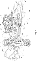
Fig. 1 is a perspective view from below of a suspension assembly produced according to this invention; -
Fig. 2 is a schematic representation of a frontal view of the suspension assembly ofFig. 1 ; -
Fig. 3 is a partially exploded perspective view of the suspension assembly ofFig. 1 ;
Fig. 4a is a frontal view of the suspension assembly ofFig. 1 in a first inclination condition; -
Fig. 4b is a detailed frontal view of the suspension assembly ofFig. 4a ; -
Fig. 5a is a frontal view of the suspension assembly ofFig. 1 in a second inclination condition; -
Fig. 5b is a detailed frontal view of the suspension assembly ofFig. 5a ; -
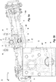
Fig. 6 is a perspective view from below of a suspension assembly produced according to a second embodiment; -
Fig. 7 is a partially exploded perspective view of the suspension assembly ofFig. 6 . - With initial reference to
Fig. 1 , 100 indicates, as a whole, a suspension assembly for a vehicle axle, in particular an agricultural vehicle or other similar vehicle suitable for off-road use. - Preferably, the
suspension assembly 100 comprises asupport structure 1 for an axle and ahousing element 2 for adriveshaft 10. - According to an embodiment shown in
Fig. 1 , thedriveshaft 10 lies in a longitudinal plane of symmetry of the vehicle and it preferably has a development that is substantially parallel or inclined to the longitudinal axis of the vehicle. - With reference to
Fig. 3 , thedriveshaft 10 advantageously comprises twoshafts universal joint 10c. - Preferably and as shown in
Figs. 1 and3 , thehousing element 2 is rotatably connected, about a transverse axis Y, perpendicular to the longitudinal axis of the aforementioned vehicle, to amain chassis 101 of the vehicle, at itsfirst extremity 22. - According to an embodiment, and with reference to
Fig. 3 , thefirst extremity 22 has a pair of arms, each one advantageously hinged about the aforementioned axis Y on asupport element 11 connected to themain chassis 101. - Preferably, the
support structure 1 is rotatably connected to thehousing element 2 about a rotational axis X, which likewise lies in a longitudinal plane of symmetry of the vehicle and is substantially parallel or inclined to the driveshaft. - According to an embodiment shown in
Fig. 3 , thehousing element 2 is rotatably connected to thesupport element 11 by means of a ball joint 12 in order to allow for the rotation about the axis X and the transverse axis that is perpendicular to it. This rotational motion will be illustrated in greater detail below. - For the purpose of a clearer understanding of the present invention,
Figs. 2 ,4a and5a show an axial XYZ triplet which represents the spatial orientation of the longitudinal axis X, of the perpendicular axis Y and of a vertical axis Z perpendicular to both. - As shown in
Figs. 1 and3 , thesupport structure 1 is secured, according to an embodiment, to themain chassis 101 of the vehicle by means of a pair ofhydraulic cylinders 3. - With reference to
Figs. 2 ,4a and5a , thesupport structure 1 comprises, preferably, a pair ofmain guides 4, which can be fixed onto themain chassis 101 and a rollingelement 5 which slides between the pair ofmain guides 4. - According to an embodiment, the
suspension assembly 100 comprises acontact element 6, secured to thesupport structure 1 and a pair offurther guides 41, which can be fixed to themain chassis 101. - Advantageously, the
contact element 6 is operationally associated with the pair offurther guides 41 in such a manner that it comes into contact with one of the further guides 41 following a rotation about the rollingelement 5. As shown inFigs. 4a and5a , when thesuspension assembly 100 is rotated, for example, anticlockwise by a predetermined angle about the axis X, thecontact element 6 defines an end-of-travel position coming into contact with one of the further guides 41 and thus constraining the motion, at least in relation to one component of the perpendicular axis Y, of thesuspension assembly 100 in relation to themain chassis 101 or, in other words, the rotation of theassembly 100 about the vertical axis Z. - Preferably, the
main guides 4 and the further guides 41 are straight and, in use, are substantially vertical. - According to a preferred embodiment and with reference to
Figs. 4a and 4b , a first inclination condition I of thesupport structure 1 in relation to the axial XYZ triplet and to themain guides 4 and the further guides 41 is shown. In this case, the rollingelement 5 is secured between the pair ofmain guides 4, located in correspondence with the maximum upward vertical motion (which is to say, in the direction that corresponds to increasing values of Z) and rotated anticlockwise by a first angle α in relation to the vertical axis Z. Moreover, following said rotation, thecontact element 6 comes into contact with one of the further guides 41, thereby defining an end-of-travel position of thesuspension assembly 100 in relation to at least one component of the perpendicular axis Y. - According to an embodiment shown in
Fig. 2 , the rollingelement 5 and thecontact element 6 are both disc-shaped. - As shown in
Figs. 2 ,4a ,4b ,5a and 5b , the further guides 41 have, preferably, a greater distance from one another than the main guides 4. According to the embodiment shown in the aforementioned figures, while the rollingelement 5 translates in relation to the vertical axis Z and rotates in relation to the longitudinal axis X, this distance from one another of the further guides 41 allows thecontact element 6 to translate both in relation to the vertical axis Z as well as in relation to the perpendicular axis Y and to rotate in relation to the longitudinal axis X. - In this manner, the further guides 41 define a boundary for the rotational-translational motion of the
contact element 6 and therefore for thesuspension assembly 100 secured to it. - According to a preferred embodiment, the further guides 41 extend as extensions of the main guides 4.
- Advantageously, each of the further guides 41 and of the
main guides 4 is produced in a single piece as shown inFig. 2 and profiled as needed. - Further preferably, and with reference to
Figs. 2 ,4a ,4b ,5a and 5b , each individual part, which is to say, each part comprising amain guide 4 extending into thefurther guide 41, includes a connection portion that is inclined in relation to the vertical axis Z and divergent from the axis Z as it moves away from the rollingelement 5. - Preferably and with reference to
Fig. 2 , thecontact element 6 is located beneath the rollingelement 5 in relation to the rotational axis X of thesupport structure 1. As can be seen inFig. 2 , when thesuspension assembly 100 has zero inclination in relation to the vertical axis Z, or rather, thesupport structure 1 has zero rotation, the rollingelement 5 and thecontact element 6 are aligned in relation to the vertical axis Z. - According to an embodiment, the
suspension assembly 100 further comprises at least onestop element 8 which can be fixed to themain chassis 101 and configured in such a manner that it comes into contact with thesupport structure 1 following a vertical motion. - With reference to
Fig. 2 , thesuspension assembly 100 advantageously comprises twostop elements 8. According to an embodiment, the twostop elements 8 are symmetrically located in relation to the longitudinal axis X. In particular, a condition is shown wherein thesuspension assembly 100 is in contact with both stop elements. In this condition, thesuspension assembly 100 preferably assumes a zero inclination in relation to the vertical axis Z. - Preferably and as shown in
Figs. 1 and2 , the further guides 41 are joined at one of their lower extremities 42 by means of a reinforcingcrossbar 9. The reinforcingcrossbar 9 is preferably located in a longitudinal position that is more advanced in relation to thecontact element 6. In this manner, the contact element can also move to a position that is vertically below thecrossbar 9. - According to an embodiment and with reference to
Figs. 5a and 5b , a second inclination condition II of thesupport structure 1 is shown, in relation to the axial XYZ triplet and to themain guides 4 and the further guides 41. In this case, the rollingelement 5 is secured between the pair ofmain guides 4 and located in correspondence with the minimum downward vertical motion (which is to say, in the direction corresponding to decreasing values of Z) and rotated anticlockwise by a second angle β in relation to the vertical axis Z. Moreover, following said rotation and translation, thecontact element 6 comes into contact with one of the further guides 41 and/or the reinforcingcrossbar 9, thus determining an end-of-travel position of thesuspension assembly 100, at least in relation to a component of the perpendicular axis Y and/or in relation to a component of the vertical axis Z. According to a preferred embodiment and with reference toFigs. 1 and3 , the rollingelement 5 and thecontact element 6 are located at an extremity opposite thehousing element 2. - Advantageously, the rolling
element 5 and thecontact element 6 are located on a side of the support structure that is substantially perpendicular to the longitudinal X axis of the vehicle. - With reference to
Figs. 6 and7 , in an alternative embodiment, thehousing element 2 is rotatably connected to thesupport structure 1 by means of abearing 12 at theextremity 21 which is opposite to that connected to thesupport element 11. - According to a preferred embodiment, the
first extremity 22 is C-shaped and each arm of thefirst extremity 22 is advantageously hinged on a respective location of thesupport element 11. This connection allows thehousing element 2 to rotate about the axis Y. - The rotational capability of the
support structure 1 about the axis X is instead obtained by means of thebearing 12. It will therefore be appreciated that the rotational axis X substantially coincides with theshaft 10a, and is therefore not necessarily parallel to a horizontal plane.
Claims (14)
- Suspension assembly (100) for a vehicle axle, in particular an agricultural vehicle or other similar vehicle suitable for off-road use, comprising a support structure (1) for an axle, a housing element (2) for a driveshaft (10), the said housing element (2) being rotatably connected, about a transverse axis (Y) that is substantially perpendicular to a longitudinal axis of the vehicle, to a support element (11) connected or connectable to a main chassis (101) of the vehicle, said support structure (1) being configured so as to be able to rotate relative to said support element (11) about a rotational axis (X) and is secured to the main chassis (101) of the vehicle by a pair of hydraulic cylinders (3), wherein said support structure (1) comprises a pair of main guides (4), which can be fixed to said main chassis (101) and a rolling element (5) which slides between the said pair of main guides (4), wherein said support structure (1) further comprises a contact element (6), secured to said support structure (1) and a pair of further guides (41), which can be fixed to said main chassis (101), said contact element (6) being located between said pair of further guides (41) and operatively connected to said pair of further guides (41) so as to come into contact with one of said further guides (41) following a rotation about the said rolling element (5), characterised in that said rolling element (5) and said contact element (6) are both disc-shaped.
- Suspension assembly (100) according to the preceding claim, wherein said main guides (4) and said further guides (41) are straight and are, in use, substantially vertical.
- Suspension assembly (100) according to any one of the preceding claims, wherein said rolling element (5) and said contact element (6) have the same diameter.
- Suspension assembly (100) according to any one of the preceding claims, wherein said further guides (41) have a distance between each other that is greater than that between said main guides (4).
- Suspension assembly (100) according to any one of the preceding claims, wherein said further guides (41) extend as extensions of said main guides (4).
- Suspension assembly (100) according to any one of the preceding claims, wherein said contact element (6) is located beneath said rolling element (5) in relation to said rotational axis (X).
- Suspension assembly (100) according to any one of the preceding claims, further comprising at least one stop element (8) that can be fixed to said main chassis (101) and configured in such a manner that it comes into contact with said support structure (1) following a vertical motion.
- Suspension assembly (100) according any one of the preceding claims, wherein said further guides (41) are joined at one of their lower extremities (42) by means of a reinforcing crossbar (9).
- Suspension assembly (100) according to any one of the preceding claims, wherein said rolling element (5) and said contact element (6) are located at an extremity that is opposite to said housing element (2).
- Suspension assembly (100) according to any one of the preceding claims, wherein each of the further guides (41) and of the corresponding main guides (4) is obtained by means of a single part.
- Suspension assembly (100) according to claim 10, wherein said single part forming each of said further guides (41) and said main guides (4) includes a connection portion that is inclined in relation to a vertical axis (Z) and divergent from said vertical axis (Z) as it moves away from said rolling element (5), said connection portion being located between said further guide (41) and said main guide (4).
- Suspension assembly (100) according to any one of the preceding claims, wherein, when the support structure (1) has zero rotation, said rolling element (5) and said contact element (6) are aligned in relation to the vertical axis of the vehicle.
- Suspension assembly (100) according to any one of the preceding claims, wherein said housing element (2) is connected to said support element (11) by means of a ball joint (12).
- Suspension assembly (100) according to any one of claims 1 to 8, wherein said housing element (2) is hinged to said support element (11) at one of its extremities (22) and is rotatably connected to the support structure (1) by means of a bearing (12) at one of its opposite extremities (21).
Priority Applications (1)
| Application Number | Priority Date | Filing Date | Title |
|---|---|---|---|
| PL18799839T PL3694731T3 (en) | 2017-10-10 | 2018-10-10 | Suspension assembly for a vehicle axle |
Applications Claiming Priority (2)
| Application Number | Priority Date | Filing Date | Title |
|---|---|---|---|
| IT102017000113851A IT201700113851A1 (en) | 2017-10-10 | 2017-10-10 | SUSPENSION UNIT FOR A VEHICLE AXLE |
| PCT/IB2018/057844 WO2019073402A1 (en) | 2017-10-10 | 2018-10-10 | Suspension assembly for a vehicle axle |
Publications (2)
| Publication Number | Publication Date |
|---|---|
| EP3694731A1 EP3694731A1 (en) | 2020-08-19 |
| EP3694731B1 true EP3694731B1 (en) | 2021-07-14 |
Family
ID=61526887
Family Applications (1)
| Application Number | Title | Priority Date | Filing Date |
|---|---|---|---|
| EP18799839.8A Active EP3694731B1 (en) | 2017-10-10 | 2018-10-10 | Suspension assembly for a vehicle axle |
Country Status (7)
| Country | Link |
|---|---|
| US (1) | US11298998B2 (en) |
| EP (1) | EP3694731B1 (en) |
| ES (1) | ES2895178T3 (en) |
| HU (1) | HUE057556T2 (en) |
| IT (1) | IT201700113851A1 (en) |
| PL (1) | PL3694731T3 (en) |
| WO (1) | WO2019073402A1 (en) |
Families Citing this family (2)
| Publication number | Priority date | Publication date | Assignee | Title |
|---|---|---|---|---|
| CA2923518C (en) * | 2015-03-10 | 2019-03-05 | Nathan Bunting | All-terrain construction equipment and methods |
| US11035096B1 (en) | 2017-03-29 | 2021-06-15 | Nathan Bunting | Construction equipment and methods |
Family Cites Families (19)
| Publication number | Priority date | Publication date | Assignee | Title |
|---|---|---|---|---|
| US1383203A (en) * | 1920-08-30 | 1921-06-28 | D M Sechler Implement & Carria | Bolster for vehicles |
| DE690821C (en) * | 1935-03-21 | 1941-10-28 | Daimler Benz Akt Ges | Driving device for motor vehicles |
| DE8111663U1 (en) * | 1981-04-16 | 1983-01-05 | "Roland" Fahrzeugplanung und -Vertrieb GmbH, 8035 Gauting | Wheel suspension for a motor vehicle |
| FR2517606A1 (en) * | 1981-12-07 | 1983-06-10 | Guerid Jean Claude | Suspended rear engine subframe - supports rear axle and can rotate about the longitudinal and transverse vehicle axes |
| EP0445164B1 (en) * | 1988-11-25 | 1992-07-15 | ZF FRIEDRICHSHAFEN Aktiengesellschaft | Installation for a steerable rigid axle on a tractor chassis |
| DE4138208C2 (en) * | 1991-11-21 | 1995-10-05 | Deere & Co | Hydropneumatically suspended wheel suspension |
| US5447321A (en) * | 1994-07-08 | 1995-09-05 | New Holland North America, Inc. | Oscillation stop mechanism for compact tractors |
| DE19643263C2 (en) * | 1996-10-19 | 2002-06-20 | Deere & Co | Suspended, suspended axle suspension |
| IT1291750B1 (en) * | 1997-05-16 | 1999-01-21 | Clark Hurth Components Spa | ELASTIC SUSPENSION STRUCTURE FOR AXLES OF INDUSTRIAL AND SIMILAR VEHICLES |
| GB9908850D0 (en) | 1999-04-20 | 1999-06-16 | New Holland Uk Ltd | Suspension stop for an agricultural vehicle |
| US7144022B2 (en) * | 2004-08-19 | 2006-12-05 | Cnh America Llc | Tractor suspension system |
| EP1972471B1 (en) * | 2007-03-22 | 2012-05-23 | CNH Italia S.p.A. | Active axle suspension system |
| US7644942B2 (en) * | 2007-03-22 | 2010-01-12 | Cnh America Llc | Active axle suspension system |
| US7721832B2 (en) * | 2007-08-01 | 2010-05-25 | Deere & Company | Walking beam suspension |
| FR2937904B1 (en) * | 2008-10-31 | 2010-11-12 | Matthieu Ballet | VEHICLE COMPRISING A RIGID AXLE MOUNTED SWIVELING ON A MOBILE SUPPORT VERTICALLY WITH RESPECT TO THE CHASSIS. |
| JP4979731B2 (en) * | 2009-03-27 | 2012-07-18 | 株式会社クボタ | Suspension device for traveling vehicle |
| US8517394B2 (en) * | 2011-08-01 | 2013-08-27 | Cnh America Llc | Adjustable suspension system for a work vehicle |
| WO2015155251A1 (en) * | 2014-04-09 | 2015-10-15 | Cnh Industrial Italia S.P.A. | Roll angle stop arrangement for a suspension system in an off-road vehicle |
| JP6754630B2 (en) * | 2016-06-27 | 2020-09-16 | 株式会社クボタ | Axle device |
-
2017
- 2017-10-10 IT IT102017000113851A patent/IT201700113851A1/en unknown
-
2018
- 2018-10-10 HU HUE18799839A patent/HUE057556T2/en unknown
- 2018-10-10 WO PCT/IB2018/057844 patent/WO2019073402A1/en not_active Ceased
- 2018-10-10 PL PL18799839T patent/PL3694731T3/en unknown
- 2018-10-10 US US16/754,441 patent/US11298998B2/en active Active
- 2018-10-10 ES ES18799839T patent/ES2895178T3/en active Active
- 2018-10-10 EP EP18799839.8A patent/EP3694731B1/en active Active
Also Published As
| Publication number | Publication date |
|---|---|
| HUE057556T2 (en) | 2022-05-28 |
| IT201700113851A1 (en) | 2019-04-10 |
| EP3694731A1 (en) | 2020-08-19 |
| PL3694731T3 (en) | 2022-01-10 |
| WO2019073402A1 (en) | 2019-04-18 |
| ES2895178T3 (en) | 2022-02-17 |
| US20200338945A1 (en) | 2020-10-29 |
| US11298998B2 (en) | 2022-04-12 |
Similar Documents
| Publication | Publication Date | Title |
|---|---|---|
| US12054028B1 (en) | Motion control systems | |
| US6439651B1 (en) | Arrangement for cabs for vehicles | |
| JP4456794B2 (en) | Suspension device allowing camber angle change | |
| US8714574B2 (en) | Independent wheel suspension of an at least slightly steerable rear wheel of a double-track vehicle | |
| CN107074051B (en) | Wheel suspension with transverse leaf springs pivoting in the center | |
| EP0825040A2 (en) | Independent steering suspension having high longitudinal compliance with high caster angle stability | |
| JP6932574B2 (en) | Axle suspension | |
| EP3694731B1 (en) | Suspension assembly for a vehicle axle | |
| US10350953B2 (en) | Vehicle with axle suspension | |
| US10137748B2 (en) | Vehicle wheel suspension | |
| JP4888189B2 (en) | Suspension device | |
| CN105365510B (en) | Vehicle suspension | |
| ES2894280T3 (en) | Rollover mechanism for road vehicles | |
| CN210284486U (en) | Swing device for scooter and scooter | |
| KR20060110381A (en) | Car suspension | |
| KR19990029094U (en) | Suspension with thrust bearing mounting structure for easy spring angle setting | |
| JPH0649445Y2 (en) | Vehicle suspension | |
| KR100993355B1 (en) | Tow Adjustment Unit for Suspension | |
| JP5056496B2 (en) | Suspension device | |
| KR102962222B1 (en) | Independent Steering System | |
| JPH0674283A (en) | Dampath struts and strut suspensions | |
| JPH0611911Y2 (en) | Cab suspension | |
| CN107984995B (en) | Wheel suspension for a rear axle of a vehicle | |
| JP2666481B2 (en) | Forklift truck rear axle suspension | |
| JPH054405Y2 (en) |
Legal Events
| Date | Code | Title | Description |
|---|---|---|---|
| STAA | Information on the status of an ep patent application or granted ep patent |
Free format text: STATUS: UNKNOWN |
|
| STAA | Information on the status of an ep patent application or granted ep patent |
Free format text: STATUS: THE INTERNATIONAL PUBLICATION HAS BEEN MADE |
|
| PUAI | Public reference made under article 153(3) epc to a published international application that has entered the european phase |
Free format text: ORIGINAL CODE: 0009012 |
|
| STAA | Information on the status of an ep patent application or granted ep patent |
Free format text: STATUS: REQUEST FOR EXAMINATION WAS MADE |
|
| 17P | Request for examination filed |
Effective date: 20200507 |
|
| AK | Designated contracting states |
Kind code of ref document: A1 Designated state(s): AL AT BE BG CH CY CZ DE DK EE ES FI FR GB GR HR HU IE IS IT LI LT LU LV MC MK MT NL NO PL PT RO RS SE SI SK SM TR |
|
| AX | Request for extension of the european patent |
Extension state: BA ME |
|
| DAV | Request for validation of the european patent (deleted) | ||
| DAX | Request for extension of the european patent (deleted) | ||
| GRAP | Despatch of communication of intention to grant a patent |
Free format text: ORIGINAL CODE: EPIDOSNIGR1 |
|
| STAA | Information on the status of an ep patent application or granted ep patent |
Free format text: STATUS: GRANT OF PATENT IS INTENDED |
|
| INTG | Intention to grant announced |
Effective date: 20210315 |
|
| GRAS | Grant fee paid |
Free format text: ORIGINAL CODE: EPIDOSNIGR3 |
|
| GRAA | (expected) grant |
Free format text: ORIGINAL CODE: 0009210 |
|
| STAA | Information on the status of an ep patent application or granted ep patent |
Free format text: STATUS: THE PATENT HAS BEEN GRANTED |
|
| AK | Designated contracting states |
Kind code of ref document: B1 Designated state(s): AL AT BE BG CH CY CZ DE DK EE ES FI FR GB GR HR HU IE IS IT LI LT LU LV MC MK MT NL NO PL PT RO RS SE SI SK SM TR |
|
| REG | Reference to a national code |
Ref country code: GB Ref legal event code: FG4D |
|
| REG | Reference to a national code |
Ref country code: DE Ref legal event code: R096 Ref document number: 602018020205 Country of ref document: DE |
|
| REG | Reference to a national code |
Ref country code: IE Ref legal event code: FG4D |
|
| REG | Reference to a national code |
Ref country code: AT Ref legal event code: REF Ref document number: 1410355 Country of ref document: AT Kind code of ref document: T Effective date: 20210815 |
|
| REG | Reference to a national code |
Ref country code: RO Ref legal event code: EPE |
|
| REG | Reference to a national code |
Ref country code: SE Ref legal event code: TRGR |
|
| REG | Reference to a national code |
Ref country code: NL Ref legal event code: FP |
|
| REG | Reference to a national code |
Ref country code: LT Ref legal event code: MG9D |
|
| REG | Reference to a national code |
Ref country code: AT Ref legal event code: UEP Ref document number: 1410355 Country of ref document: AT Kind code of ref document: T Effective date: 20210714 |
|
| PG25 | Lapsed in a contracting state [announced via postgrant information from national office to epo] |
Ref country code: RS Free format text: LAPSE BECAUSE OF FAILURE TO SUBMIT A TRANSLATION OF THE DESCRIPTION OR TO PAY THE FEE WITHIN THE PRESCRIBED TIME-LIMIT Effective date: 20210714 Ref country code: HR Free format text: LAPSE BECAUSE OF FAILURE TO SUBMIT A TRANSLATION OF THE DESCRIPTION OR TO PAY THE FEE WITHIN THE PRESCRIBED TIME-LIMIT Effective date: 20210714 Ref country code: FI Free format text: LAPSE BECAUSE OF FAILURE TO SUBMIT A TRANSLATION OF THE DESCRIPTION OR TO PAY THE FEE WITHIN THE PRESCRIBED TIME-LIMIT Effective date: 20210714 Ref country code: LT Free format text: LAPSE BECAUSE OF FAILURE TO SUBMIT A TRANSLATION OF THE DESCRIPTION OR TO PAY THE FEE WITHIN THE PRESCRIBED TIME-LIMIT Effective date: 20210714 Ref country code: PT Free format text: LAPSE BECAUSE OF FAILURE TO SUBMIT A TRANSLATION OF THE DESCRIPTION OR TO PAY THE FEE WITHIN THE PRESCRIBED TIME-LIMIT Effective date: 20211115 Ref country code: NO Free format text: LAPSE BECAUSE OF FAILURE TO SUBMIT A TRANSLATION OF THE DESCRIPTION OR TO PAY THE FEE WITHIN THE PRESCRIBED TIME-LIMIT Effective date: 20211014 |
|
| REG | Reference to a national code |
Ref country code: ES Ref legal event code: FG2A Ref document number: 2895178 Country of ref document: ES Kind code of ref document: T3 Effective date: 20220217 |
|
| PG25 | Lapsed in a contracting state [announced via postgrant information from national office to epo] |
Ref country code: LV Free format text: LAPSE BECAUSE OF FAILURE TO SUBMIT A TRANSLATION OF THE DESCRIPTION OR TO PAY THE FEE WITHIN THE PRESCRIBED TIME-LIMIT Effective date: 20210714 Ref country code: GR Free format text: LAPSE BECAUSE OF FAILURE TO SUBMIT A TRANSLATION OF THE DESCRIPTION OR TO PAY THE FEE WITHIN THE PRESCRIBED TIME-LIMIT Effective date: 20211015 |
|
| REG | Reference to a national code |
Ref country code: DE Ref legal event code: R097 Ref document number: 602018020205 Country of ref document: DE |
|
| PG25 | Lapsed in a contracting state [announced via postgrant information from national office to epo] |
Ref country code: DK Free format text: LAPSE BECAUSE OF FAILURE TO SUBMIT A TRANSLATION OF THE DESCRIPTION OR TO PAY THE FEE WITHIN THE PRESCRIBED TIME-LIMIT Effective date: 20210714 |
|
| PLBE | No opposition filed within time limit |
Free format text: ORIGINAL CODE: 0009261 |
|
| STAA | Information on the status of an ep patent application or granted ep patent |
Free format text: STATUS: NO OPPOSITION FILED WITHIN TIME LIMIT |
|
| REG | Reference to a national code |
Ref country code: HU Ref legal event code: AG4A Ref document number: E057556 Country of ref document: HU |
|
| REG | Reference to a national code |
Ref country code: CH Ref legal event code: PL |
|
| PG25 | Lapsed in a contracting state [announced via postgrant information from national office to epo] |
Ref country code: SM Free format text: LAPSE BECAUSE OF FAILURE TO SUBMIT A TRANSLATION OF THE DESCRIPTION OR TO PAY THE FEE WITHIN THE PRESCRIBED TIME-LIMIT Effective date: 20210714 Ref country code: SK Free format text: LAPSE BECAUSE OF FAILURE TO SUBMIT A TRANSLATION OF THE DESCRIPTION OR TO PAY THE FEE WITHIN THE PRESCRIBED TIME-LIMIT Effective date: 20210714 Ref country code: EE Free format text: LAPSE BECAUSE OF FAILURE TO SUBMIT A TRANSLATION OF THE DESCRIPTION OR TO PAY THE FEE WITHIN THE PRESCRIBED TIME-LIMIT Effective date: 20210714 Ref country code: AL Free format text: LAPSE BECAUSE OF FAILURE TO SUBMIT A TRANSLATION OF THE DESCRIPTION OR TO PAY THE FEE WITHIN THE PRESCRIBED TIME-LIMIT Effective date: 20210714 |
|
| 26N | No opposition filed |
Effective date: 20220419 |
|
| REG | Reference to a national code |
Ref country code: BE Ref legal event code: MM Effective date: 20211031 |
|
| PG25 | Lapsed in a contracting state [announced via postgrant information from national office to epo] |
Ref country code: MC Free format text: LAPSE BECAUSE OF FAILURE TO SUBMIT A TRANSLATION OF THE DESCRIPTION OR TO PAY THE FEE WITHIN THE PRESCRIBED TIME-LIMIT Effective date: 20210714 |
|
| PG25 | Lapsed in a contracting state [announced via postgrant information from national office to epo] |
Ref country code: LU Free format text: LAPSE BECAUSE OF NON-PAYMENT OF DUE FEES Effective date: 20211010 Ref country code: BE Free format text: LAPSE BECAUSE OF NON-PAYMENT OF DUE FEES Effective date: 20211031 |
|
| PG25 | Lapsed in a contracting state [announced via postgrant information from national office to epo] |
Ref country code: LI Free format text: LAPSE BECAUSE OF NON-PAYMENT OF DUE FEES Effective date: 20211031 Ref country code: CH Free format text: LAPSE BECAUSE OF NON-PAYMENT OF DUE FEES Effective date: 20211031 |
|
| PG25 | Lapsed in a contracting state [announced via postgrant information from national office to epo] |
Ref country code: IE Free format text: LAPSE BECAUSE OF NON-PAYMENT OF DUE FEES Effective date: 20211010 |
|
| PG25 | Lapsed in a contracting state [announced via postgrant information from national office to epo] |
Ref country code: CY Free format text: LAPSE BECAUSE OF FAILURE TO SUBMIT A TRANSLATION OF THE DESCRIPTION OR TO PAY THE FEE WITHIN THE PRESCRIBED TIME-LIMIT Effective date: 20210714 |
|
| P01 | Opt-out of the competence of the unified patent court (upc) registered |
Effective date: 20230710 |
|
| PG25 | Lapsed in a contracting state [announced via postgrant information from national office to epo] |
Ref country code: MK Free format text: LAPSE BECAUSE OF FAILURE TO SUBMIT A TRANSLATION OF THE DESCRIPTION OR TO PAY THE FEE WITHIN THE PRESCRIBED TIME-LIMIT Effective date: 20210714 |
|
| PG25 | Lapsed in a contracting state [announced via postgrant information from national office to epo] |
Ref country code: MT Free format text: LAPSE BECAUSE OF FAILURE TO SUBMIT A TRANSLATION OF THE DESCRIPTION OR TO PAY THE FEE WITHIN THE PRESCRIBED TIME-LIMIT Effective date: 20210714 |
|
| REG | Reference to a national code |
Ref country code: HU Ref legal event code: HC9C Owner name: CARRARO S.P.A., IT |
|
| PGFP | Annual fee paid to national office [announced via postgrant information from national office to epo] |
Ref country code: IT Payment date: 20250922 Year of fee payment: 8 |
|
| PGFP | Annual fee paid to national office [announced via postgrant information from national office to epo] |
Ref country code: HU Payment date: 20251027 Year of fee payment: 8 |
|
| PGFP | Annual fee paid to national office [announced via postgrant information from national office to epo] |
Ref country code: NL Payment date: 20251021 Year of fee payment: 8 |
|
| PGFP | Annual fee paid to national office [announced via postgrant information from national office to epo] |
Ref country code: DE Payment date: 20251021 Year of fee payment: 8 |
|
| PGFP | Annual fee paid to national office [announced via postgrant information from national office to epo] |
Ref country code: GB Payment date: 20251022 Year of fee payment: 8 |
|
| PGFP | Annual fee paid to national office [announced via postgrant information from national office to epo] |
Ref country code: AT Payment date: 20251022 Year of fee payment: 8 |
|
| PGFP | Annual fee paid to national office [announced via postgrant information from national office to epo] |
Ref country code: FR Payment date: 20251030 Year of fee payment: 8 |
|
| PGFP | Annual fee paid to national office [announced via postgrant information from national office to epo] |
Ref country code: TR Payment date: 20251006 Year of fee payment: 8 |
|
| PGFP | Annual fee paid to national office [announced via postgrant information from national office to epo] |
Ref country code: SE Payment date: 20251021 Year of fee payment: 8 |
|
| PGFP | Annual fee paid to national office [announced via postgrant information from national office to epo] |
Ref country code: CZ Payment date: 20251002 Year of fee payment: 8 |
|
| PGFP | Annual fee paid to national office [announced via postgrant information from national office to epo] |
Ref country code: BG Payment date: 20251023 Year of fee payment: 8 Ref country code: PL Payment date: 20251002 Year of fee payment: 8 |
|
| PGFP | Annual fee paid to national office [announced via postgrant information from national office to epo] |
Ref country code: RO Payment date: 20251003 Year of fee payment: 8 |
|
| PGFP | Annual fee paid to national office [announced via postgrant information from national office to epo] |
Ref country code: ES Payment date: 20251216 Year of fee payment: 8 |