EP3694248B1 - Response frame delay duration setting method, device, and system - Google Patents
Response frame delay duration setting method, device, and system Download PDFInfo
- Publication number
- EP3694248B1 EP3694248B1 EP18873893.4A EP18873893A EP3694248B1 EP 3694248 B1 EP3694248 B1 EP 3694248B1 EP 18873893 A EP18873893 A EP 18873893A EP 3694248 B1 EP3694248 B1 EP 3694248B1
- Authority
- EP
- European Patent Office
- Prior art keywords
- acknowledgment
- sta
- frame
- delay duration
- acknowledgment frame
- Prior art date
- Legal status (The legal status is an assumption and is not a legal conclusion. Google has not performed a legal analysis and makes no representation as to the accuracy of the status listed.)
- Active
Links
Images







Classifications
-
- H—ELECTRICITY
- H04—ELECTRIC COMMUNICATION TECHNIQUE
- H04L—TRANSMISSION OF DIGITAL INFORMATION, e.g. TELEGRAPHIC COMMUNICATION
- H04L1/00—Arrangements for detecting or preventing errors in the information received
- H04L1/12—Arrangements for detecting or preventing errors in the information received by using return channel
- H04L1/16—Arrangements for detecting or preventing errors in the information received by using return channel in which the return channel carries supervisory signals, e.g. repetition request signals
- H04L1/18—Automatic repetition systems, e.g. Van Duuren systems
- H04L1/1829—Arrangements specially adapted for the receiver end
- H04L1/1854—Scheduling and prioritising arrangements
-
- H—ELECTRICITY
- H04—ELECTRIC COMMUNICATION TECHNIQUE
- H04L—TRANSMISSION OF DIGITAL INFORMATION, e.g. TELEGRAPHIC COMMUNICATION
- H04L1/00—Arrangements for detecting or preventing errors in the information received
- H04L1/12—Arrangements for detecting or preventing errors in the information received by using return channel
- H04L1/16—Arrangements for detecting or preventing errors in the information received by using return channel in which the return channel carries supervisory signals, e.g. repetition request signals
- H04L1/18—Automatic repetition systems, e.g. Van Duuren systems
- H04L1/1829—Arrangements specially adapted for the receiver end
- H04L1/1858—Transmission or retransmission of more than one copy of acknowledgement message
-
- H—ELECTRICITY
- H04—ELECTRIC COMMUNICATION TECHNIQUE
- H04B—TRANSMISSION
- H04B7/00—Radio transmission systems, i.e. using radiation field
- H04B7/02—Diversity systems; Multi-antenna system, i.e. transmission or reception using multiple antennas
- H04B7/04—Diversity systems; Multi-antenna system, i.e. transmission or reception using multiple antennas using two or more spaced independent antennas
- H04B7/0413—MIMO systems
- H04B7/0452—Multi-user MIMO systems
-
- H—ELECTRICITY
- H04—ELECTRIC COMMUNICATION TECHNIQUE
- H04B—TRANSMISSION
- H04B7/00—Radio transmission systems, i.e. using radiation field
- H04B7/02—Diversity systems; Multi-antenna system, i.e. transmission or reception using multiple antennas
- H04B7/04—Diversity systems; Multi-antenna system, i.e. transmission or reception using multiple antennas using two or more spaced independent antennas
- H04B7/06—Diversity systems; Multi-antenna system, i.e. transmission or reception using multiple antennas using two or more spaced independent antennas at the transmitting station
-
- H—ELECTRICITY
- H04—ELECTRIC COMMUNICATION TECHNIQUE
- H04L—TRANSMISSION OF DIGITAL INFORMATION, e.g. TELEGRAPHIC COMMUNICATION
- H04L1/00—Arrangements for detecting or preventing errors in the information received
- H04L1/12—Arrangements for detecting or preventing errors in the information received by using return channel
- H04L1/16—Arrangements for detecting or preventing errors in the information received by using return channel in which the return channel carries supervisory signals, e.g. repetition request signals
- H04L1/1607—Details of the supervisory signal
- H04L1/1685—Details of the supervisory signal the supervisory signal being transmitted in response to a specific request, e.g. to a polling signal
-
- H—ELECTRICITY
- H04—ELECTRIC COMMUNICATION TECHNIQUE
- H04L—TRANSMISSION OF DIGITAL INFORMATION, e.g. TELEGRAPHIC COMMUNICATION
- H04L1/00—Arrangements for detecting or preventing errors in the information received
- H04L1/12—Arrangements for detecting or preventing errors in the information received by using return channel
- H04L1/16—Arrangements for detecting or preventing errors in the information received by using return channel in which the return channel carries supervisory signals, e.g. repetition request signals
- H04L1/18—Automatic repetition systems, e.g. Van Duuren systems
-
- H—ELECTRICITY
- H04—ELECTRIC COMMUNICATION TECHNIQUE
- H04L—TRANSMISSION OF DIGITAL INFORMATION, e.g. TELEGRAPHIC COMMUNICATION
- H04L1/00—Arrangements for detecting or preventing errors in the information received
- H04L1/12—Arrangements for detecting or preventing errors in the information received by using return channel
- H04L1/16—Arrangements for detecting or preventing errors in the information received by using return channel in which the return channel carries supervisory signals, e.g. repetition request signals
- H04L1/18—Automatic repetition systems, e.g. Van Duuren systems
- H04L1/1812—Hybrid protocols; Hybrid automatic repeat request [HARQ]
-
- H—ELECTRICITY
- H04—ELECTRIC COMMUNICATION TECHNIQUE
- H04L—TRANSMISSION OF DIGITAL INFORMATION, e.g. TELEGRAPHIC COMMUNICATION
- H04L1/00—Arrangements for detecting or preventing errors in the information received
- H04L1/12—Arrangements for detecting or preventing errors in the information received by using return channel
- H04L1/16—Arrangements for detecting or preventing errors in the information received by using return channel in which the return channel carries supervisory signals, e.g. repetition request signals
- H04L1/18—Automatic repetition systems, e.g. Van Duuren systems
- H04L1/1829—Arrangements specially adapted for the receiver end
- H04L1/1864—ARQ related signaling
-
- H—ELECTRICITY
- H04—ELECTRIC COMMUNICATION TECHNIQUE
- H04W—WIRELESS COMMUNICATION NETWORKS
- H04W28/00—Network traffic management; Network resource management
- H04W28/02—Traffic management, e.g. flow control or congestion control
- H04W28/04—Error control
Definitions
- This application relates to the field of wireless communications technologies, and in particular, to an acknowledgment frame delay duration setting method and apparatus.
- a multiple-input multiple-output (Multiple-Input Multiple-Output, MIMO) technology is used in several emerging wireless communications standards such as the Institute of Electrical and Electronics Engineers (IEEE) 802.11 standard, so that a plurality of mobile stations (Station, STA) communicate with one or more access points (Access Point, AP) by sharing a channel resource, to achieve a high data throughput.
- IEEE Institute of Electrical and Electronics Engineers 802.11 standard
- a STA when a STA receives a data frame (Packet) sent by an AP, the STA needs to feed back an acknowledgment (ACK) frame to the AP to notify the AP that the STA has received the data frame.
- Packet data frame
- ACK acknowledgment
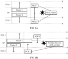
- FIG 1A is a schematic diagram of a conflict between acknowledgment frames according to an example implementation of this application.
- FIG 1A when an AP simultaneously receives acknowledgment frames fed back by a plurality of STAs, a conflict (interference) is caused between the acknowledgment frames received by the AP.
- FIG 1B is a schematic diagram of a conflict between an acknowledgment frame and a data frame according to an example implementation of this application. As shown in FIG 1B , when an AP receives, in a process of sending a data frame to a STA 1, an acknowledgment frame fed back by a STA 2, a conflict (interference) is caused between the acknowledgment frame and the data frame.
- an AP Due to interference caused between data, an AP is likely to incorrectly determine that the AP receives no acknowledgment frame sent by a STA, in other words, determine that a data frame sent to the STA is lost. Consequently, the AP subsequently polls on the STA whether the STA receives the data frame, causing a waste of wireless communications resources.
- WO2016107524 relates to data transmission method, acquisition method, transmission apparatus and acquisition apparatus.
- This application discloses an acknowledgment frame delay duration setting method and apparatus, to resolve a problem in a related technology.
- a same AP does not simultaneously receive acknowledgment frames sent by STAs in a same group. This prevents an AP from incorrectly determining, due to a conflict between an acknowledgment frame and a data frame and a conflict between acknowledgment frames, that the AP receives no acknowledgment frame sent by a STA, thereby eliminating polling overheads of the AP, and avoiding a waste of wireless communications resources.
- overheads of a frame preamble, a frame header, and the like are reduced due to use of an aggregated frame, so that network overheads can be effectively reduced.
- a MIMO controller may separately set a use count of the acknowledgment frame delay duration, to control a quantity of times the STA uses the acknowledgment frame delay duration after receiving a data frame.
- a “module” mentioned in this specification is a program or an instruction that is stored in a memory and that can implement some functions.
- a “unit” mentioned in this specification is a functional structure obtained through logic-based division. The “unit” may be implemented by only hardware, or implemented by a combination of software and hardware.
- FIG 2A is a schematic diagram of a system architecture of an acknowledgment frame delay duration setting system to which an implementation of this application is applied.
- An acknowledgment frame delay duration setting method in this application is applied to the acknowledgment frame delay duration setting system.
- the acknowledgment frame delay duration setting system includes a plurality of network devices and a plurality of STAs.
- the network device includes at least one MIMO controller and at least one AP.
- the AP is wirelessly connected to the STA, and the AP is connected to the MIMO controller by using a switch.
- the switch is connected to both the AP and the MIMO controller in a wired/wireless manner.
- a wired connection manner includes an optical fiber connection and an Ethernet connection.
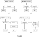
- FIG 2B is a schematic diagram of a manner in which an AP is connected to a MIMO controller and to which an implementation of this application is applied.
- the AP is connected to the MIMO controller by using one switch (as shown in FIG 2B (1), both an AP 1 and an AP 2 are connected to a MIMO controller by using one switch), or by using a plurality of switches (as shown in FIG 2B (2), an AP 2 is connected to a MIMO controller by using two switches; and as shown in FIG 2B (3), an AP 2 is connected to a MIMO controller by using three switches).
- every two switches may be directly connected (as shown in FIG 2B (2), a switch 1 is directly connected to a switch 2; and as shown in FIG 2B (3), a switch 3 is directly connected to both a switch 1 and a switch 2), or may be connected by using a router (as shown in FIG 2B (4), a switch 1 is connected to a switch 2 by using a router 1).
- a connection between switches and a connection between a switch and a router are wired/wireless connections.
- the MIMO controller may be an independent device or may be integrated into an access point controller (Access Point Controller, AC).
- the MIMO controller When the MIMO controller is an independent device, the MIMO controller usually runs on a general-purpose computer, for example, runs on a central processing unit (Central Processing Unit, CPU) of the computer, and performs hardware (such as a CPU hard core, a graphics processing unit (Graphics Processing Unit, GPU), or a field programmable gate array (FieldProgrammable Gate Array, FPGA)) acceleration.
- CPU Central Processing Unit
- FPGA field programmable gate array
- the MIMO controller is usually used as a functional module of the AC.
- the MIMO controller communicates with an AP by using a communications tunnel between the AP and the AC.
- FIG 3 is a schematic structural diagram of a network device to which an example implementation of this application is applied.
- the network device is not claimed as such in the present application.
- the methods described with reference to figures 5A-5B , 6A-6B , 7A-7B , and 8 should be construed accordingly.
- the network device includes a processor 31, a network interface 32, a cache 33, a memory 34, and a bus 35.
- the processor 31 includes one or more processing cores.
- the processor 31 runs a software program and a module, to implement various functional applications and data processing.
- the network interface 32 is used by the network device to communicate with another network device.
- the memory 34 and the cache 33 are both connected to the processor 31 through the bus 35.
- the memory 34 may be configured to store the software program and the module.
- the memory 34 may store an application program module 36 required by at least one function.
- the application program module 36 includes at least an obtaining module program 361, a sending module program 362, a setting module program 363, a receiving module program 364, and a deletion module program 365.
- the obtaining module program 361 is configured to: obtain first acknowledgment frame delay duration corresponding to a first mobile station STA; and obtain second acknowledgment frame delay duration corresponding to a second STA, where the second STA and the first STA are STAs in a same group.
- the sending module program 362 is configured to: send, to the first STA, a first indication frame carrying the first acknowledgment frame delay duration, so that the first STA feeds back an acknowledgment frame after a delay of the first acknowledgment frame delay duration when receiving a data frame; send, to the second STA, a second indication frame carrying the second acknowledgment frame delay duration, so that the second STA feeds back an acknowledgment frame after a delay of the second acknowledgment frame delay duration when receiving a data frame; send the first acknowledgment frame delay duration to a first access point AP, so that the first AP forwards the first acknowledgment frame delay duration to the first STA, where the first AP is an AP associated with the first STA; send a use count to the first AP, so that the first AP forwards the use count to the first STA; send, to the first STA in a form of an aggregated frame, the first indication frame carrying the first acknowledgment frame delay duration, where the aggregated frame further includes a data frame; after sending the data frame to the first STA,
- the setting module program 363 is configured to: before the first acknowledgment frame delay duration corresponding to the first mobile station STA is obtained, allocate the first acknowledgment frame delay duration to the first STA; after allocating the first acknowledgment frame delay duration to the first STA, set the use count of the first acknowledgment frame delay duration; and set, based on the first acknowledgment timeout duration, the first acknowledgment frame delay duration corresponding to the first STA, where the first acknowledgment timeout duration is longer than the first acknowledgment frame delay duration.
- the receiving module program 364 is configured to: before the first acknowledgment frame delay duration corresponding to the first mobile station STA is obtained, receive the first acknowledgment timeout duration corresponding to the first STA that is sent by the MIMO controller, and add the first STA and the first acknowledgment timeout duration to a prestored correspondence between a STA and acknowledgment timeout duration.
- the deletion module program 365 is configured to delete the first STA and the first acknowledgment timeout duration from the correspondence.
- the memory 34 may be implemented by any type of volatile or nonvolatile storage device or a combination thereof, such as a static random access memory (SRAM), an electrically erasable programmable read-only memory (EEPROM), an erasable programmable read-only memory (EPROM), a programmable read-only memory (PROM), a read-only memory (ROM), a magnetic memory, a flash memory, a magnetic disk, or an optical disc.
- SRAM static random access memory
- EEPROM electrically erasable programmable read-only memory
- EPROM erasable programmable read-only memory
- PROM programmable read-only memory
- ROM read-only memory
- FIG 3 constitutes no limitation on the network device, and the network device may include more or fewer components than those shown in the figure, or combine some components, or have different component arrangements.
- FIG 4 is a schematic structural diagram of a first STA to which an example implementation of this application is applied.
- the first STA includes a processor 41, a network interface 42, a cache 43, a memory 44, and a bus 45.
- the processor 41 includes one or more processing cores.
- the processor 41 runs a software program and a module, to implement various functional applications and data processing.
- the network interface 42 is used by the first STA to communicate with another network device.
- the memory 44 and the cache 43 are both connected to the processor 41 through the bus 45.
- the memory 44 may be configured to store the software program and the module.
- the memory 44 may store an application program module 46 required by at least one function.
- the application program module 46 includes at least a receiving module program 461, a feedback module program 462, a deletion module program 463, and a calculation module program 464.
- the receiving module program 461 is configured to: receive a first indication frame sent by a first AP, and obtain and store first acknowledgment frame delay duration corresponding to the first STA that is carried in the first indication frame, where the first AP is an AP associated with the first STA; and obtain and store the first acknowledgment frame delay duration corresponding to the first STA and a use count corresponding to the first acknowledgment frame delay duration that are carried in the first indication frame.
- the feedback module program 462 is configured to: each time a data frame sent by the first AP is received, feed back an acknowledgment frame to the first AP after a delay of the first acknowledgment frame delay duration; subtract 1 from the stored use count corresponding to the first acknowledgment frame delay duration; and if a result obtained after 1 is subtracted from the use count corresponding to the first acknowledgment frame delay duration is less than 0, delete the first acknowledgment frame delay duration and the use count corresponding to the first acknowledgment frame delay duration, and feed back the acknowledgment frame to the first AP after a delay of default delay duration; or if a result obtained after 1 is subtracted from the use count corresponding to the first acknowledgment frame delay duration is not less than 0, feed back the acknowledgment frame to the first AP after a delay of the first acknowledgment frame delay duration.
- the deletion module program 463 is configured to: when a first acknowledgment frame delay duration cancelation message sent by the first AP is received, delete, the stored first acknowledgment frame delay duration.
- the calculation module program 464 is configured to: each time a data frame sent by the first AP is received, subtract, 1 from the stored use count corresponding to the first acknowledgment frame delay duration.
- the memory 44 may be implemented by any type of volatile or nonvolatile storage device or a combination thereof, such as a static random access memory (SRAM), an electrically erasable programmable read-only memory (EEPROM), an erasable programmable read-only memory (EPROM), a programmable read-only memory (PROM), a read-only memory (ROM), a magnetic memory, a flash memory, a magnetic disk, or an optical disc.
- SRAM static random access memory
- EEPROM electrically erasable programmable read-only memory
- EPROM erasable programmable read-only memory
- PROM programmable read-only memory
- ROM read-only memory
- first STA shown in FIG 4 constitutes no limitation on the first STA, and the first STA may include more or fewer components than those shown in the figure, or combine some components, or have different component arrangements.
- FIG 5A is a flowchart of an acknowledgment frame delay duration setting method according to an example implementation of this application.
- the method includes the following several steps.
- Step 501 A network device obtains first acknowledgment frame delay duration corresponding to a first STA.
- the network device is a MIMO controller or a first AP, and the first AP is an AP associated with the first STA.
- the network device When the network device is the MIMO controller, before obtaining the first acknowledgment frame delay duration corresponding to the first STA, the network device allocates the first acknowledgment frame delay duration to the first STA.
- the MIMO controller allocates the corresponding first acknowledgment frame delay duration to the first STA based on a network delay of the first STA.
- the network device When the network device is the first AP, the network device receives the first acknowledgment frame delay duration corresponding to the first STA that is sent by the MIMO controller.
- the first STA sends an association request to the first AP. After receiving the association request sent by the first STA, the first AP determines that the first STA is to be associated with the first AP. In this case, the first AP obtains the first acknowledgment frame delay duration corresponding to the first STA.
- Step 502 The network device sends, to the first STA, a first indication frame carrying the first acknowledgment frame delay duration.
- the network device When the network device is the MIMO controller, the network device sends the first acknowledgment frame delay duration to the first AP, so that the first AP forwards the first acknowledgment frame delay duration to the first STA.
- the network device When the network device is the first AP, the network device sends, to the first STA, the first indication frame carrying the first acknowledgment frame delay duration.
- Management frame subtypes 1101 (Action) and 1110 (Action No ACK) are used for the first indication frame carrying the first acknowledgment frame delay duration.
- a difference between the two subtypes lies in that, when receiving an Action frame, the first STA needs to reply to the first AP with an acknowledgment frame; but when receiving an Action No ACK frame, the first STA does not need to reply to the first AP with an acknowledgment frame.
- the Action frame helps provide reliable transmission
- the Action No ACK frame helps reduce network overheads.
- the Action No ACK type has a similar principle to the Action type, and therefore is not described in this implementation.
- the Action frame includes two main fields: a category (Category) field, used to indicate a specific subtype of the Action frame, and a description (Action Details) field, used to describe the Action frame.
- Category Category
- Description Action Details
- Table 1 shows possible values of code in the category field of the Action frame.
- Table 1 Code Meaning See subclause Robust Group addressed privacy 14 Multihop 8.5.18 Yes Yes 15 Self-protected 8.5.16 No No 16 Reserved - - - 17 Reserved (used by WFA) - - - 18-125 Reserved - - - 126 Vendor-specific Protected 8.5.6 Yes No 127 Vendor-specific 8.5.6 No No 128-255 Error - - - -
- any value that is of the code in Table 1 and that is not defined in an existing protocol or that has no agreed meaning may be used in the category field of the Action frame.
- the code in the category field of the Action frame is 16.
- the first AP may form an aggregated frame by using the first indication frame and the data frame and then send the aggregated frame to the first STA.
- Overheads of a frame preamble, a frame header, and the like are reduced due to use of the aggregated frame, so that network overheads can be effectively reduced.
- step 502 may be replaced with the following step:
- the first AP sends, to the first STA in a form of an aggregated frame, a first indication frame carrying the first acknowledgment frame delay duration, where the aggregated frame further includes a data frame.
- the first indication frame and the data frame are sent through aggregation by using an aggregate MAC protocol data unit (Aggregate MAC Protocol Data Unit, A-MPDU).
- A-MPDU aggregate MAC Protocol Data Unit
- the first AP determines the first acknowledgment frame delay duration corresponding to the first STA, there are two data frames that need to be sent to the first STA.
- the first AP aggregates the two data frames to obtain downlink data, as shown in Table 2.
- Table 2 A-MPDU subframe 2 Data frame
- Table 3 shows a possible location of the first indication frame in data frames in an aggregated frame obtained after the first indication frame and the data frames are aggregated. It should be noted that, the location of the first indication frame in the data frames is not limited in this implementation. Table 3 A-MPDU subframe 1 Indication frame A-MPDU subframe 2 Data frame A-MPDU subframe 3 Data frame A-MPDU subframe 2 Data frame A-MPDU subframe 1 Indication frame A-MPDU subframe 3 Data frame A-MPDU subframe 2 Data frame A-MPDU subframe 3 Data frame A-MPDU subframe 1 Indication frame
- the first AP When sending the first data frame to the first STA, the first AP sends the data frame and the first indication frame to the first STA through aggregation. Overheads of a frame preamble, a frame header, and the like can be reduced due to use of the aggregated frame, so that network overheads can be effectively reduced.
- the step of sending the first indication frame may be omitted, to reduce the network overheads.
- Step 503 The first STA receives the first indication frame sent by the first AP, and obtains and stores the first acknowledgment frame delay duration corresponding to the first STA that is carried in the first indication frame.
- the first STA when the first AP sends, to the first STA in the form of the aggregated frame, the first indication frame carrying the first acknowledgment frame delay duration, the first STA receives the aggregated frame sent by the first AP, to obtain the first indication frame and the data frame that are included in the aggregated frame, and feeds back an acknowledgment frame to the first AP after a delay of the first acknowledgment frame delay duration.
- each STA After receiving a data frame sent by the first AP, each STA feeds back an acknowledgment frame to the first AP after a delay of corresponding acknowledgment frame delay duration. Because an interval between a time at which each STA receives the data frame and a time at which the STA determines to send the acknowledgment frame to the first AP is very short and is even 0, the first AP does not need to send a query request to each STA.
- Block Acknowledgment Request BAR
- SIFS SIFS between a BAR and a block acknowledgment
- BA Block Acknowledgment
- FIG 5B is a schematic diagram of acknowledgment frames received by a first AP according to an example implementation of this application.
- the first AP sets acknowledgment frame delay duration corresponding to a STA 1 to 16 ⁇ s, and sets acknowledgment frame delay duration corresponding to a STA 2 to 40 ⁇ s.
- the first AP simultaneously sends data frames to the STA 1 and the STA 2, and a data stream length is 500 ⁇ s.
- the STA 1 feeds back an acknowledgment frame to the first AP after a delay of 16 ⁇ s.
- the STA 2 feeds back an acknowledgment frame to the first AP after a delay of 40 ⁇ s.
- the network device sends, to the first STA, the first indication frame carrying the first acknowledgment frame delay duration, so that when receiving a data frame sent by the first AP associated with the first STA, the first STA feeds back an acknowledgment frame to the first AP after a delay of the first acknowledgment frame delay duration. Because STAs in a same group usually have different acknowledgment frame delay duration, a same AP does not simultaneously receive acknowledgment frames sent by STAs in a same group.
- a STA after receiving a data frame, a STA usually needs to feed back an acknowledgment frame to a first AP after an SIFS. Because an acknowledgment timeout time of the first AP is set for the short interframe space, after acknowledgment frame delay duration is allocated to each STA, acknowledgment timeout duration of the first AP for each STA further needs to be set based on the acknowledgment frame delay duration of each STA, to prevent the first AP from prematurely determining that data is lost and starting a re-sending procedure.
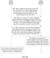
- FIG 6A and FIG. 6B are a flowchart of an acknowledgment frame delay duration setting method according to another example implementation of this application.
- an example in which the method is used in the system architecture of the acknowledgment frame delay duration setting system shown in FIG. 2A is used for description. The method includes the following several steps.
- Step 601 A first AP receives first acknowledgment timeout duration corresponding to a first STA that is sent by a MIMO controller, and adds the first STA and the first acknowledgment timeout duration to a prestored correspondence between a STA and acknowledgment timeout duration.
- the first AP receives first acknowledgment frame delay duration of 80 ⁇ s corresponding to the first STA that is sent by the MIMO controller, and sets the first acknowledgment timeout duration corresponding to the first STA to 100 ⁇ s based on the first acknowledgment frame delay duration.
- the MIMO controller may set different acknowledgment timeout duration for different STAs, or may set same acknowledgment timeout duration for different STAs.
- the acknowledgment timeout duration is longer than acknowledgment frame delay duration corresponding to a STA having the longest acknowledgment frame delay duration.
- Table 4 shows that the MIMO controller may set different acknowledgment timeout duration for different STAs connected to a same AP.
- Table 4 AP STA Acknowledgment timeout duration ( ⁇ s) AP 1 STA 1 36 AP 1 STA 2 50
- Table 5 shows that the MIMO controller may set same acknowledgment timeout duration for different STAs connected to a same AP.
- Table 5 AP STA Acknowledgment timeout duration ( ⁇ s) AP 1 STA 1 50 AP 1 STA 2 50
- the MIMO controller sends, to the first AP in a TLV format, the first acknowledgment timeout duration corresponding to the first STA.
- the first AP after receiving the first acknowledgment timeout duration corresponding to the first STA that is sent by the MIMO controller, the first AP feeds back an acknowledgment setting message to the MIMO controller.
- the first AP may reply to the MIMO controller with a complex acknowledgment message carrying information related to the first STA.
- the first AP may alternatively reply to the MIMO controller with a brief acknowledgment message carrying no original setting.
- the MIMO controller sends, to the first AP, the first acknowledgment timeout duration and the first acknowledgment frame delay duration that correspond to the first STA, where a MAC address of the first STA is 0x0A1122334455, the first acknowledgment frame delay duration is 50 ⁇ s, and the first acknowledgment timeout duration is 100 ⁇ s.
- the MIMO controller sends, to the first AP, a setting message that carries the first acknowledgment timeout duration and indicates that the first AP does not need to feed back the acknowledgment setting message.
- Table 6 shows a possible message format of the setting message (a time unit is ⁇ s).
- Table 6 Type Len Value 00 (message type) 1 0 (indicating a setting request) 01 (message identifier) 2 Message ID 02 (MAC address of the first STA) 6 0x0A1122334455 03 (acknowledgment frame delay duration) 2 50 04 (acknowledgment timeout duration) 2 100 05 (whether an acknowledgment message needs to be replied with) 1 0 (no acknowledgment is required) ... ... ...
- the MIMO controller sends, to the first AP, a setting message that carries the first acknowledgment timeout duration and indicates that the first AP needs to feed back the complex acknowledgment message.
- Table 7 shows a possible message format of the setting message (a time unit is ⁇ s).
- Table 7 Type Len Value 00 (message type) 1 1 (indicating a setting reply) 01 (message identifier) 2 Message ID 02 (MAC address of the first STA) 6 0x0A1122334455 03 (first acknowledgment frame delay duration) 2 50 04 (first acknowledgment timeout duration) 2 100 05 (whether an acknowledgment message needs to be replied with) 1 1 (complex acknowledgment) ... ... ...
- the MIMO controller sends, to the first AP, a setting message that carries the first acknowledgment timeout duration and indicates that the first AP needs to feed back the brief acknowledgment message.
- Table 8 shows a possible message format of the setting message (a time unit is ⁇ s).
- Table 8 Type Len Value 00 (message type) 1 1 (indicating a setting reply) 01 (message identifier) 2 Message ID 02 (MAC address of the first STA) 6 0x0A1122334455 03 (first acknowledgment frame delay duration) 2 50 04 (first acknowledgment timeout duration) 2 100 05 (whether an acknowledgment message needs to be replied with) 1 2 (brief acknowledgment) ... ... ...
- a possible message format of the complex acknowledgment message fed back by the first AP is shown in Table 9 (a time unit is ⁇ s).
- Table 9 Type Len Value 00 (message type) 1 1 (indicating a complex acknowledgment reply) 01 (message identifier) 2 Message ID 02 (MAC address of the first STA) 6 0x0A1122334455 03 (first acknowledgment frame delay duration) 2 50 04 (first acknowledgment timeout duration) 2 100 05 1 0 ... ... ...
- a possible message format of the brief acknowledgment message fed back by the first AP is shown in Table 10 (a time unit is ⁇ s).
- the first AP feeds back the acknowledgment setting message to the MIMO controller in a TLV format.
- the acknowledgment timeout duration of each STA may also be set by a first AP associated with each STA in addition to the MIMO controller.
- the first AP receives the first acknowledgment frame delay duration corresponding to the first STA that is sent by the MIMO controller, sets, based on the first acknowledgment frame delay duration, the first acknowledgment timeout duration corresponding to the first STA, and adds the first STA and the first acknowledgment timeout duration to the prestored correspondence between a STA and acknowledgment timeout duration.
- the first acknowledgment timeout duration is longer than the first acknowledgment frame delay duration.
- Step 602 The first AP sets, based on the first acknowledgment timeout duration, the first acknowledgment frame delay duration corresponding to the first STA.
- the first AP receives the first acknowledgment timeout duration of 100 ⁇ s corresponding to the first STA that is sent by the MIMO controller, and sets the first acknowledgment frame delay duration corresponding to the first STA to 80 ⁇ s based on the first acknowledgment timeout duration.
- the first acknowledgment frame delay duration corresponding to the first STA may also be set by the MIMO controller in addition to the first AP.
- the first AP receives the first acknowledgment frame delay duration corresponding to the first STA that is sent by the MIMO controller, and sends the first acknowledgment frame delay duration to the first STA.
- Step 603 The first AP sends, to the first STA, a first indication frame carrying the first acknowledgment frame delay duration.
- Step 604 The first STA receives the first indication frame sent by the first AP, and obtains and stores the first acknowledgment frame delay duration corresponding to the first STA that is carried in the first indication frame.
- Step 605 The first AP sends a data frame to the first STA.
- the first AP and the first STA each are provided with two interfaces: a first interface and a second interface. Power consumption on the first interface is greater than power consumption on the second interface.
- the first AP sends the first indication frame and the data frame to the STA through a first interface, and listens to and receives, through a second interface, an acknowledgment frame fed back by each STA, to reduce power consumption of the first AP.
- the first STA feeds back an acknowledgment frame to the first AP through a first interface, and listens to and receives, through a second interface, an indication frame and a data frame that are sent by each first AP.
- Power consumption on the first interface is greater than power consumption on the second interface, to reduce power consumption of the first STA.
- the first AP when the first AP enters a sleep state, the first AP performs listening through the second interface.
- the first AP feeds back an acknowledgment frame to the first STA through the second interface.
- the first AP may immediately feed back the acknowledgment frame to the first STA, or may not feed back the acknowledgment frame to the first STA until an environment permits, or may feed back the acknowledgment frame to the first STA when the first AP is in an idle state.
- An occasion on which the first AP feeds back the acknowledgment frame to the first STA is not limited in this implementation.
- the first STA when the first STA enters a sleep state, the first STA performs listening through the second interface.
- the first STA feeds back an acknowledgment frame to the first AP through the second interface after a delay of the first acknowledgment frame delay duration.
- the first AP may not simultaneously send data frames or indication frames to the plurality of STAs, to prevent the plurality of STAs from simultaneously feeding back acknowledgment frames to the first AP.
- the first AP adds the first STA and the first acknowledgment frame delay duration to a prestored correspondence between a STA and acknowledgment frame delay duration.
- the first AP needs to perform the following steps:
- the first STA When receiving, again, a first indication frame carrying acknowledgment frame delay duration, the first STA replaces locally stored acknowledgment frame delay duration with the acknowledgment frame delay duration in the first indication frame.
- the first STA stores acknowledgment frame delay duration of 90 ⁇ s; when receiving a first indication frame that carries acknowledgment frame delay duration of 120 ⁇ s and that is sent by the first AP, the first STA obtains the acknowledgment frame delay duration of 120 ⁇ s carried in the first indication frame and replaces 90 ⁇ s with 120 ⁇ s for storage.
- the acknowledgment frame delay duration of the STAs may be reset by the MIMO controller, or the acknowledgment frame delay duration of the STAs may be reset by the AP.
- a specific value of a time interval for sequentially sending data frames is not limited in this implementation.
- Step 606 Each time receiving a data frame sent by the first AP, the first STA feeds back an acknowledgment frame to the first AP after a delay of the first acknowledgment frame delay duration.
- Step 607 After sending the data frame to the first STA, the first AP re-sends the data frame to the first STA if receiving, within the first acknowledgment timeout duration, no data frame fed back by the first STA.
- the first AP determines that the data frame sent to the STA is lost. In this case, the first AP re-sends the data frame to the first STA.
- a network device sends, to the first STA, the first indication frame carrying the first acknowledgment frame delay duration, so that when receiving a data frame sent by the first AP associated with the first STA, the first STA feeds back an acknowledgment frame to the first AP after a delay of the first acknowledgment frame delay duration. Because STAs in a same group usually have different acknowledgment frame delay duration, a same AP does not simultaneously receive acknowledgment frames sent by STAs in a same group.
- the acknowledgment timeout duration of the first AP for each STA further needs to be set based on the acknowledgment frame delay duration of each STA, to prevent the first AP from prematurely determining that data is lost and starting a re-sending procedure.
- the MIMO controller may actively send a first acknowledgment timeout duration cancelation message to the first AP according to a requirement (for example, after a network MIMO phase ends), to control the first AP to cancel acknowledgment timeout duration for some or all of STAs connected to the first AP.
- Step 608 When receiving a first acknowledgment timeout duration cancelation message for the first STA that is sent by the MIMO controller, the first AP sends a first acknowledgment frame delay duration cancelation message to the first STA.
- An acknowledgment timeout time for a STA is set by the MIMO controller based on acknowledgment frame delay duration of the STA.
- the first AP further needs to cancel the acknowledgment frame delay duration of the first STA after canceling an acknowledgment timeout time corresponding to the first STA, so that the first STA and the first AP both restore to a default mechanism.
- a first possible message format is shown in Table 11, and a new encoding manner is used for the message format of the first acknowledgment timeout duration cancelation message.
- Table 11 Type Len Value 00 (message type) 1 2 (indicating a setting request) 01 (message identifier) 2 Message ID 02 (MAC address of the first STA) 6 0x0A1122334455 04 (whether an acknowledgment message needs to be replied with) 1 0 (no acknowledgment is required)11 (complex acknowledgment)/2 (brief acknowledgment) ... ... ...
- the first AP feeds back an acknowledgment cancelation message to the MIMO controller.
- the first AP may reply to the MIMO controller with a complex acknowledgment message carrying information related to the first STA.
- the first AP may alternatively reply to the MIMO controller with a brief acknowledgment message carrying no original setting.
- Table 12 a possible message format of the complex acknowledgment message is shown in Table 12 (a time unit is ⁇ s).
- Table 12 Type Len Value 00 (message type) 1 1 (indicating a complex acknowledgment reply) 01 (message identifier) 2
- Message ID 02 (MAC address of the STA) 6 0x0A1122334455 04 (whether an acknowledgment message needs to be replied with) 1 0 (no acknowledgment is required) ... ... ...
- Table 13 a possible message format of the brief acknowledgment message is shown in Table 13 (a time unit is ⁇ s).
- Table 13 Type Len Value 00 (message type) 1 2 (indicating a brief acknowledgment reply) 01 (message identifier) 2 Message ID 04 (whether an 1 0 (no acknowledgment is acknowledgment message needs to be replied with) required) ... ... ... ...
- a second possible message format is shown in Table 14.
- a message format of a setting message is used for the message format of the first acknowledgment timeout duration cancelation message, but the first acknowledgment timeout duration is set to 0 ⁇ s.
- the first AP When receiving the first acknowledgment timeout duration cancelation message for the first STA that is sent by the MIMO controller, the first AP obtains the first acknowledgment timeout duration (0 ⁇ s) carried in the first acknowledgment timeout duration cancelation message, and deletes the first STA and the first acknowledgment timeout duration from the correspondence.
- Table 14 Type Len Value 00 (message type) 1 0 (indicating a setting request) 01 (message identifier) 2 Message ID 02 (MAC address of the first STA) 6 0x0A1122334455 03 (first acknowledgment timeout duration) 2 0 04 (whether an acknowledgment message needs to be replied with) 1 0 (no acknowledgment is required)/1 (complex acknowledgment)/2 (brief acknowledgment) ... ... ...
- the first AP feeds back an acknowledgment cancelation message to the MIMO controller.
- Table 15 A possible message format of a complex acknowledgment message is shown in Table 15 (a time unit is ⁇ s).
- Table 15 Type Len Value 00 (message type) 1 1 (indicating a setting reply) 01 (message identifier) 2
- Message ID 02 (MAC address of the first STA) 6 0x0A1122334455 03 (first acknowledgment timeout duration) 2 0 ... ... ...
- Table 16 A possible message format of a brief acknowledgment message is shown in Table 16 (a time unit is ⁇ s).
- Table 16 Type Len Value 00 (message type) 1 2 (indicating a brief setting reply) 01 (message identifier) 2 Message ID ... ... ...
- the MIMO controller sends the first acknowledgment timeout duration cancelation message to the first AP in a TLV format, and the first AP feeds back the acknowledgment cancelation message to the MIMO controller in a TLV format.
- a message type of the first acknowledgment frame delay duration cancelation message is a first indication frame carrying acknowledgment frame delay duration of 0 ⁇ s.
- a message type of the first acknowledgment frame delay duration cancelation message is an Action frame.
- an Action frame with a category field being 16 and a description field being 3 is defined as a first indication frame for canceling the acknowledgment frame delay duration.
- the first AP sends, to the first STA, the Action frame with the category field being 16 and the description field being 3.
- Step 609 When receiving the first acknowledgment frame delay duration cancelation message sent by the first AP, the first STA deletes the stored first acknowledgment frame delay duration.
- the first STA After the first STA deletes the stored first acknowledgment frame delay duration, the first STA restores to a default mechanism, to be specific, each time receiving a data frame sent by the first AP, the first STA feeds back an acknowledgment frame to the first AP after an SIFS.
- the first STA after deleting the stored first acknowledgment frame delay duration, the first STA feeds back an acknowledgment cancelation message to the first AP.
- the STA may feed back the acknowledgment cancelation message to the first AP at a media access control (Media Access Control, MAC) layer by using an ACK frame, or may feed back the acknowledgment cancelation message to the first AP at a protocol interaction layer by using an Action frame.
- Media Access Control Media Access Control
- Step 610 The first AP deletes the first STA and the first acknowledgment timeout duration from the correspondence.
- step 608 to step 610 shown in FIG 6B is merely a possible implementation. During actual application, step 608 to step 610 may be implemented at any location after step 601. An execution location of step 608 to step 610 in step 601 to step 607 is not limited in this implementation.
- the MIMO controller may actively send, by using the first AP, the first acknowledgment frame delay duration cancelation message to the first STA according to a requirement (for example, after the network MIMO phase ends), to control the STA to cancel the acknowledgment frame delay duration.
- the method includes the following step: Step 611: When receiving a second acknowledgment frame delay duration cancelation message for the first STA that is sent by the MIMO controller, the first AP sends a first acknowledgment frame delay duration cancelation message to the first STA.
- the first AP sends, to the first STA in a form of an aggregated frame, a first indication frame for canceling the acknowledgment frame delay duration, where the aggregated frame further includes a data frame.
- the first AP deletes the first STA and the first acknowledgment timeout duration from the correspondence.
- step 611 is implemented before step 609.
- a MIMO controller may separately set a use count of an acknowledgment frame delay duration, to control a quantity of times a STA uses the acknowledgment frame delay duration after receiving a data frame.
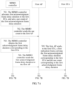
- FIG 7A and FIG 7B are a flowchart of an acknowledgment frame delay duration setting method according to still another example implementation of this application.
- an example in which the method is used in the system architecture of the acknowledgment frame delay duration setting system shown in FIG 1 is used for description. The method includes the following several steps.
- Step 701 A MIMO controller allocates first acknowledgment frame delay duration to a first STA, and sets a use count of the first acknowledgment frame delay duration.
- Step 702 The MIMO controller sends the use count to a first AP.
- the first AP is an AP associated with the first STA.
- Step 703 The MIMO controller obtains the first acknowledgment frame delay duration corresponding to the first STA.
- Step 704 The MIMO controller sends the first acknowledgment frame delay duration to the first AP.
- the MIMO controller may separately send the first acknowledgment frame delay duration and the use count of the first acknowledgment frame delay duration to the first AP, or may combine the first acknowledgment frame delay duration and the use count of the first acknowledgment frame delay duration into one message and then send the message to the first AP.
- Step 705 The first AP sends, to the first STA, a first indication frame carrying the first acknowledgment frame delay duration corresponding to the first STA and the use count corresponding to the first acknowledgment frame delay duration.
- the first indication frame may be used to indicate a single delay or may be used to indicate a plurality of delays.
- the first acknowledgment frame delay duration carried in the first indication frame can be used only once; or when the first indication frame indicates a plurality of delays, the first indication frame carries the use count corresponding to the first acknowledgment frame delay duration.
- the first indication frame further has a function of canceling the acknowledgment frame delay duration, and different functions are distinguished based on an ACK delay time field (type) in an Action Details field of the first indication frame.
- Table 17 shows a possible meaning of the ACK delay time field in the description field of the first indication frame, and the meaning of the ACK delay time field is a meaning of the first indication frame. It should be noted that, a correspondence between an ACK delay time field and a meaning in Table 17 constitutes no limitation on the meaning corresponding to the ACK delay time field.
- Table 18 shows a possible frame format of the first indication frame when the first indication frame is used to indicate a single delay.
- Table 18 ACK delay time field Delay time most significant bit Delay time least significant bit 0 (single delay) 8 time most significant bits 8 time least significant bits
- Table 19 shows a possible frame format of the first indication frame when the first indication frame is used to indicate a plurality of delays.
- Table 19 ACK delay time field Delay time most significant bit Delay time least significant bit Delay count most significant bit Delay count least significant bit 1 (a plurality of delays) 8 time most significant bits 8 time least significant bits 8 time most significant bits 8 time least significant bits 8 time least significant bits 8 time least significant bits
- the use count is set by the MIMO controller when the MIMO controller allocates the corresponding first acknowledgment frame delay duration to the first STA.
- Step 706 The first STA receives the first indication frame sent by the first AP, and obtains and stores the first acknowledgment frame delay duration corresponding to the first STA and the use count corresponding to the first acknowledgment frame delay duration that are carried in the first indication frame.
- Step 707 Each time receiving a data frame sent by the first AP, the first STA subtracts 1 from the stored use count corresponding to the first acknowledgment frame delay duration.
- Step 708 If a result obtained after 1 is subtracted from the use count corresponding to the first acknowledgment frame delay duration is less than 0, the first STA deletes the first acknowledgment frame delay duration and the use count corresponding to the first acknowledgment frame delay duration, and feeds back an acknowledgment frame to the first AP after a delay of default delay duration.
- the first STA deletes the first acknowledgment frame delay duration and the use count corresponding to the first acknowledgment frame delay duration, and executes a default mechanism, to be specific, feeds back the acknowledgment frame to the first AP after a delay of the default delay duration.
- the first STA when the first STA receives a first acknowledgment frame delay duration cancelation message sent by the first AP, even if the use count corresponding to the first acknowledgment frame delay duration is greater than 0, the first STA still deletes the stored first acknowledgment frame delay duration, and executes the default mechanism.
- Step 709 If a result obtained after 1 is subtracted from the use count corresponding to the first acknowledgment frame delay duration is not less than 0, the first STA feeds back an acknowledgment frame to the first AP after a delay of the first acknowledgment frame delay duration.
- the first STA feeds back the acknowledgment frame to the first AP after a delay of the first acknowledgment frame delay duration.
- step 707 to step 709 may be replaced with the following step Q1 to step Q3:
- a network device sends, to the first STA, the first indication frame carrying the first acknowledgment frame delay duration, so that when receiving a data frame sent by the first AP associated with the first STA, the first STA feeds back an acknowledgment frame to the first AP after a delay of the first acknowledgment frame delay duration. Because STAs in a same group usually have different acknowledgment frame delay duration, a same AP does not simultaneously receive acknowledgment frames sent by STAs in a same group.
- the MIMO controller may separately set the use count of the acknowledgment frame delay duration, to control the quantity of times the STA uses the acknowledgment frame delay duration after receiving the data frame.
- FIG 8 is a flowchart of an acknowledgment frame delay duration setting method according to yet another example implementation of this application.
- Step 801 A network device obtains first acknowledgment frame delay duration corresponding to a first mobile station STA.
- Step 802 The network device sends the first acknowledgment frame delay duration to the first STA, so that the first STA feeds back an acknowledgment frame after a delay of the first acknowledgment frame delay duration when receiving a data frame.
- Step 803 The network device obtains second acknowledgment frame delay duration corresponding to a second STA.
- Step 804 The network device sends the second acknowledgment frame delay duration to the second STA, so that the second STA feeds back an acknowledgment frame after a delay of the second acknowledgment frame delay duration when receiving a data frame.
- the first STA and the second STA are STAs in a same group, and the two STAs meet at least one of the following cases:
- the network device may set different acknowledgment frame delay duration for the first STA and the second STA (in other words, the first acknowledgment frame delay duration is different from the second acknowledgment frame delay duration), or set same acknowledgment frame delay duration for the first STA and the second STA (in other words, the first acknowledgment frame delay duration is the same as the second acknowledgment frame delay duration), but does not simultaneously send data frames to the first STA and the second STA.
- the first AP sends, to the first STA, a first indication frame carrying the first acknowledgment frame delay duration, so that when receiving a data frame sent by the first AP, the first STA feeds back an acknowledgment frame to the first AP after a delay of the first acknowledgment frame delay duration. Because STAs in a same group have different acknowledgment frame delay duration, a same AP does not simultaneously receive acknowledgment frames sent by STAs in a same group.
- the plurality of STAs correspond to different acknowledgment frame delay duration.
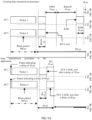
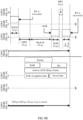
- FIG 9A and FIG 9B are a schematic diagram of comparison between an existing data transmission procedure and a data transmission procedure in this application according to an example implementation of this application.
- two APs, two STAs, and a data stream length of 500 ⁇ s are used as an example.
- an AP 1 and an AP 2 respectively send data to a STA 1 and a STA 2 at a network MIMO phase (500 ⁇ s)
- the STA 1 and the STA 2 feed back acknowledgment frames (24 ⁇ s).
- an ACK conflict is caused between the acknowledgment frames fed back by the STA 1 and the STA 2. Because neither the AP 1 nor the AP 2 receives an acknowledgment frame sent by a corresponding STA, the AP 1 and the AP 2 start to contend for an air interface medium (34 ⁇ s+63 ⁇ s).
- the AP 1 sends a BAR (24 ⁇ s) after obtaining a medium access right
- the STA 1 sends a BA (24 ⁇ s) after an SIFS after the BAR is sent
- the AP 1 determines that the STA 1 receives data that is sent by the AP 1 at the network MIMO phase.
- the AP 2 sends a BAR to the STA 2 (24 ⁇ s) after backoff (34 ⁇ s+63 ⁇ s), the STA 2 sends a BA (24 ⁇ s) after an SIFS after the BAR is sent, and after receiving the BA sent by the STA 2, the AP 2 determines that the STA 2 receives data that is sent by the AP 1 at the network MIMO phase.
- duration required for determining, by exchanging the BARs and the BAs, whether the STA 1 and the STA 2 receive the data is 362 ⁇ s.
- an AP 1 and an AP 2 respectively send data and corresponding first indication frames carrying acknowledgment frame delay duration to a STA 1 and a STA 2 (504 ⁇ s).
- Acknowledgment frame delay duration corresponding to the STA 1 is 16 ⁇ s
- acknowledgment frame delay duration corresponding to the STA 2 is 40 ⁇ s.
- the STA 1 feeds back an acknowledgment frame to the AP (24 ⁇ s) after a delay of 16 ⁇ s.
- the STA 2 feeds back an acknowledgment frame to the AP (24 ⁇ s) after a delay of 40 ⁇ s. Both the AP 1 and the AP 2 receive the acknowledgment frames sent by the corresponding STAs.
- the network device and the STA include corresponding hardware structures and/or software modules for performing the functions.
- the example units and algorithm steps described with reference to the implementations disclosed in this application can be implemented in a form of hardware or a combination of hardware and computer software in the implementations of this application. Whether a function is performed by hardware or hardware driven by computer software depends on particular applications and design constraint conditions of the technical solutions. A person skilled in the art may use different methods to implement the described functions for each particular application, but it should not be considered that the implementation falls beyond the scope of the technical solutions in the implementations of this application.
- FIG 10 is a possible schematic structural diagram of a network device 1000 according to an implementation of this application.
- the network device is not claimed as such in the present application.
- service data and a signaling message are processed by the processor 1002, and modulated by the transmitter 1001 (for example, a baseband signal is modulated into a high frequency signal) to generate a downlink signal, and the downlink signal is transmitted to the STA through the antenna.
- the demodulation or modulation function may be alternatively completed by the processor 1002.
- the processor 1002 is further configured to perform the process in step 1002 in FIG 10 and/or another process in the technical solutions described in this application.
- the network device 1000 may further include a memory 1003.
- the memory 1003 is configured to store program code and data of the network device 1000.
- the network device may further include a transceiver 1004.
- the transceiver 1004 is configured to support the network device in communicating with another network entity (for example, a network device in a core network).
- another network entity for example, a network device in a core network.
- the transceiver 1004 may be an S1-U interface, configured to support the network device in communicating with a serving gateway (Serving Gateway, SGW for short), or the transceiver 1004 may be an S1-MME interface, configured to support the network device in communicating with a mobility management entity (Mobility Management Entity, MME for short).
- MME Mobility Management Entity
- FIG 10 merely shows a simplified design of the network device 1000.
- the network device 1000 may include any quantity of transmitters, receivers, processors, controllers, memories, transceivers, or the like, and all network devices that can implement the implementations of this application shall fall within the protection scope of the implementations of this application.
- FIG 11 is a simplified schematic diagram of a possible design structure of a first STA1100 according to an implementation of this application.
- the first STA 1100 includes a transmitter 1101, a receiver 1102, and a processor 1103.
- the processor 1103 may also be a controller, and is represented as a "controller/processor 1103" in FIG 11 .
- the first STA 1100 may further include a modem processor 1104.
- the modem processor 1104 may include an encoder 1105, a modulator 1106, a decoder 1107, and a demodulator 1108.
- the transmitter 1101 adjusts (for example, performs analog conversion, filtering, amplification, and up-conversion on) an output sample and generates an uplink signal.
- the uplink signal is transmitted to the network device in the foregoing implementations through an antenna.
- the antenna receives a downlink signal transmitted by the network device in the foregoing implementations.
- the receiver 1102 adjusts (for example, performs filtering, amplification, down-conversion, and digitalization on) the signal received from the antenna and provides an input sample.
- the encoder 1105 receives service data and a signaling message that are to be sent on an uplink, and processes (for example, formats, encodes, and interleaves) the service data and the signaling message.
- the modulator 1106 further processes (for example, performs symbol mapping and modulation on) encoded service data and an encoded signaling message, and provides an output sample.
- the demodulator 1108 processes (for example, demodulates) the input sample and provides a symbol estimate.
- the decoder 1107 processes (for example, de-interleaves and decodes) the symbol estimate, and provides decoded data and a decoded signaling message that are to be sent to the first STA 1100.
- the encoder 1108, the modulator 1106, the demodulator 1108, and the decoder 1107 may be implemented by the combined modem processor 1106. These units perform processing based on a radio access technology (for example, access technologies of LTE and other evolved systems) used in a radio access network. It should be noted that, when the first STA 1100 does not include the modem processor 1106, the foregoing functions of the modem processor 1106 may also be implemented by the processor 1103.
- the processor 1103 controls and manages an action of the first STA 1100, and is configured to perform a processing process performed by the first STA 1100 in the foregoing implementations of this application.
- the processor 1103 is further configured to perform the process in step 604 in FIG 6A and/or another process in the technical solutions described in this application.
- the first STA 1100 may further include a memory 1109.
- the memory 1109 is configured to store program code and data used for the first STA 1100.
- a processor configured to perform a function of the foregoing network device or first STA in the implementations of this application may be a central processing unit (Central Processing Unit, CPU), a general-purpose processor, a digital signal processor (Digital Signal Processor, DSP), an application-specific integrated circuit (Application-Specific Integrated Circuit, ASIC), a field programmable gate array (Field Programmable Gate Array, FPGA) or another programmable logic device, a transistor logic device, a hardware component, or any combination thereof.
- the processor may implement or execute various example logical blocks, modules, and circuits described with reference to content disclosed in the implementations of this application.
- the processor may be a combination implementing a computing function, for example, a combination including one or more microprocessors, or a combination of a DSP and a microprocessor.
- An example storage medium is coupled to a processor, so that the processor can read information from the storage medium and can write information into the storage medium.
- the storage medium may be a component of the processor.
- the processor and the storage medium may be located in an ASIC.
- the ASIC may be located in the network device or the first STA.
- the processor and the storage medium may exist in the network device or the first STA as discrete components.
- the obtaining module 1201 is configured to implement the function of step 501.
- the sending module 1202 is configured to implement the function of step 502.
- the obtaining module is configured to implement the function of at least one of step 703, step 801, and step 803.
- the sending module 1202 is configured to implement the function of at least one of step 603, step 607, step 608, step 611, step 702, step 704, step 705, step 802, and step 804.
- FIG 12B is a block diagram of an acknowledgment frame delay duration setting apparatus according to an implementation of this application.
- the acknowledgment frame delay duration setting apparatus may include an obtaining module 1201, a sending module 1202, a receiving module 1203, a setting module 1204, and a deletion module 1205.
- the receiving module 1203 is configured to implement the function of step 601.
- the setting module 1204 is configured to implement the function of at least one of step 602 and step 701.
- the deletion module 1205 is configured to implement the function of step 610.
- the obtaining module 1201 may be implemented by the processor 31 in FIG 3 by executing the obtaining module program 361 in the memory 34;
- the sending module 1202 may be implemented by the processor 31 in FIG 3 by executing the sending module program 362 in the memory 34;
- the receiving module 1203 may be implemented by the processor 31 in FIG 3 by executing the receiving module program 364 in the memory 34;
- the setting module 1204 may be implemented by the processor 31 in FIG 3 by executing the setting module program 363 in the memory 34;
- the deletion module 1205 may be implemented by the processor 31 in FIG 3 by executing the deletion module program 365 in the memory 34.
- FIG 13A is a block diagram of an acknowledgment frame delay duration setting apparatus according to another implementation of this application.
- the acknowledgment frame delay duration setting apparatus may be implemented as all or a part of a first STA by using software, hardware, or a combination thereof.
- the acknowledgment frame delay duration setting apparatus may include a receiving module 1301 and a feedback module 1302.
- the receiving module 1301 is configured to implement the function of step 503.
- the feedback module 1302 is configured to implement the function of step 504.
- the receiving module 1301 is configured to implement the function of at least one of step 604 and step 706.
- the feedback module 1302 is configured to implement the function of at least one of step 606, step 708, and step 709.
- FIG 13B is a block diagram of an acknowledgment frame delay duration setting apparatus according to another implementation of this application.
- the acknowledgment frame delay duration setting apparatus may include a receiving module 1301, a feedback module 1302, a deletion module 1303, and a calculation module 1304.
- the deletion module 1303 is configured to implement the function of step 609.
- the calculation module 1304 is configured to implement the function of step 707.
- the receiving module 1301 may be implemented by the processor 41 in FIG 4 by executing the receiving module program 461 in the memory 44;
- the feedback module 1302 may be implemented by the processor 41 in FIG 4 by executing the feedback module program 462 in the memory 44;
- the deletion module 1303 may be implemented by the processor 41 in FIG 4 by executing the deletion module program 463 in the memory 44;
- the calculation module 1304 may be implemented by the processor 41 in FIG 4 by executing the calculation module program 464 in the memory 44.
- acknowledgment frame delay duration setting apparatuses when the acknowledgment frame delay duration setting apparatuses provided in the foregoing implementations set acknowledgment frame delay duration, only division of the foregoing functional modules is used as an example for description. During actual application, the foregoing functions can be allocated to different functional modules for implementation according to a requirement, to be specific, an inner structure of the network device is divided into different functional modules and an inner structure of the STA is divided into different functional modules, to implement all or some of the functions described above.
- the acknowledgment frame delay duration setting apparatuses provided in the foregoing implementations belong to a same concept as the acknowledgment frame delay duration setting method implementations. For specific implementation processes of the apparatuses, refer to the method implementations. Details are not described herein again.
- the program may be stored in a computer-readable storage medium.
- the storage medium may be a read-only memory, a magnetic disk, an optical disc, or the like.
Landscapes
- Engineering & Computer Science (AREA)
- Computer Networks & Wireless Communication (AREA)
- Signal Processing (AREA)
- Mobile Radio Communication Systems (AREA)
- Detection And Prevention Of Errors In Transmission (AREA)
Description
- This application relates to the field of wireless communications technologies, and in particular, to an acknowledgment frame delay duration setting method and apparatus.
- To meet increased bandwidth requirements of a wireless communications system, a multiple-input multiple-output (Multiple-Input Multiple-Output, MIMO) technology is used in several emerging wireless communications standards such as the Institute of Electrical and Electronics Engineers (IEEE) 802.11 standard, so that a plurality of mobile stations (Station, STA) communicate with one or more access points (Access Point, AP) by sharing a channel resource, to achieve a high data throughput.
- To improve reliability of MIMO communication, when a STA receives a data frame (Packet) sent by an AP, the STA needs to feed back an acknowledgment (ACK) frame to the AP to notify the AP that the STA has received the data frame.
- During actual application, a same AP may perform concurrent data transmission with different STAs, and interference is likely to be caused due to the concurrent data transmission.
FIG 1A is a schematic diagram of a conflict between acknowledgment frames according to an example implementation of this application. As shown inFIG 1A , when an AP simultaneously receives acknowledgment frames fed back by a plurality of STAs, a conflict (interference) is caused between the acknowledgment frames received by the AP.FIG 1B is a schematic diagram of a conflict between an acknowledgment frame and a data frame according to an example implementation of this application. As shown inFIG 1B , when an AP receives, in a process of sending a data frame to aSTA 1, an acknowledgment frame fed back by aSTA 2, a conflict (interference) is caused between the acknowledgment frame and the data frame. - Due to interference caused between data, an AP is likely to incorrectly determine that the AP receives no acknowledgment frame sent by a STA, in other words, determine that a data frame sent to the STA is lost. Consequently, the AP subsequently polls on the STA whether the STA receives the data frame, causing a waste of wireless communications resources.
-
WO2016107524 relates to data transmission method, acquisition method, transmission apparatus and acquisition apparatus. - This application discloses an acknowledgment frame delay duration setting method and apparatus, to resolve a problem in a related technology.
- The invention has been defined in the independent claims. Further specific technical features have been defined in the dependent claims.
- Because STAs in a same group usually have different acknowledgment frame delay duration, a same AP does not simultaneously receive acknowledgment frames sent by STAs in a same group. This prevents an AP from incorrectly determining, due to a conflict between an acknowledgment frame and a data frame and a conflict between acknowledgment frames, that the AP receives no acknowledgment frame sent by a STA, thereby eliminating polling overheads of the AP, and avoiding a waste of wireless communications resources.
- Based on certain principles disclosed in the present disclosure, overheads of a frame preamble, a frame header, and the like are reduced due to use of an aggregated frame, so that network overheads can be effectively reduced.
- Based on certain principles disclosed in the present disclosure, a MIMO controller may separately set a use count of the acknowledgment frame delay duration, to control a quantity of times the STA uses the acknowledgment frame delay duration after receiving a data frame.
-
-
FIG 1A is a schematic diagram of a conflict between acknowledgment frames according to an example implementation of this application; -
FIG 1B is a schematic diagram of a conflict between an acknowledgment frame and a data frame according to an example implementation of this application; -
FIG 2A is a schematic diagram of a system architecture of an acknowledgment frame delay duration setting system to which an implementation of this application is applied; -
FIG 2B is a schematic diagram of a manner in which an AP is connected to a MIMO controller and to which an implementation of this application is applied; -
FIG 3 is a schematic structural diagram of a network device to which an example implementation of this application is applied; -
FIG 4 is a schematic structural diagram of a STA to which an example implementation of this application is applied; -
FIG 5A is a flowchart of an acknowledgment frame delay duration setting method according to an example implementation of this application; -
FIG 5B is a schematic diagram of acknowledgment frames received by a first AP according to an example implementation of this application; -
FIG 6A andFIG 6B are a flowchart of an acknowledgment frame delay duration setting method according to another example implementation of this application; -
FIG 7A andFIG 7B are a flowchart of an acknowledgment frame delay duration setting method according to still another example implementation of this application; -
FIG 8 is a flowchart of an acknowledgment frame delay duration setting method according to yet another example implementation of this application; -
FIG 9A andFIG 9B are a schematic diagram of comparison between an existing data transmission procedure and a data transmission procedure in this application according to an example implementation of this application; -
FIG 10 is a possible schematic structural diagram of a network device according to an implementation of this application; -
FIG 11 is a simplified schematic diagram of a possible design structure of a STA according to an implementation of this application; -
FIG 12A is a block diagram of an acknowledgment frame delay duration setting apparatus according to an implementation of this application; -
FIG 12B is a block diagram of an acknowledgment frame delay duration setting apparatus according to an implementation of this application; -
FIG 13A is a block diagram of an acknowledgment frame delay duration setting apparatus according to another implementation of this application; and -
FIG 13B is a block diagram of an acknowledgment frame delay duration setting apparatus according to another implementation of this application. - To make the objectives, technical solutions, and advantages of this invention clearer, the following further describes various implementations in detail with reference to the accompanying drawings. The implementations described below are not all claimed, they are included to help understanding the context of the invention. While the description refers to various implementations, the embodiments of the invention are those which comprise at least all the features of an independent claim. Any implementation which does not fall within the scope of the claims does not form part of the invention, but rather included as an illustrative example that is useful for understanding the invention.
- A "module" mentioned in this specification is a program or an instruction that is stored in a memory and that can implement some functions. A "unit" mentioned in this specification is a functional structure obtained through logic-based division. The "unit" may be implemented by only hardware, or implemented by a combination of software and hardware.
-
FIG 2A is a schematic diagram of a system architecture of an acknowledgment frame delay duration setting system to which an implementation of this application is applied. An acknowledgment frame delay duration setting method in this application is applied to the acknowledgment frame delay duration setting system. The acknowledgment frame delay duration setting system includes a plurality of network devices and a plurality of STAs. The network device includes at least one MIMO controller and at least one AP. - The AP is wirelessly connected to the STA, and the AP is connected to the MIMO controller by using a switch. The switch is connected to both the AP and the MIMO controller in a wired/wireless manner. A wired connection manner includes an optical fiber connection and an Ethernet connection.
- It should be noted that, a quantity of switches between the AP and the MIMO controller is not limited in the system architecture of the acknowledgment frame delay duration setting system.
FIG 2B is a schematic diagram of a manner in which an AP is connected to a MIMO controller and to which an implementation of this application is applied. The AP is connected to the MIMO controller by using one switch (as shown inFIG 2B (1), both anAP 1 and anAP 2 are connected to a MIMO controller by using one switch), or by using a plurality of switches (as shown inFIG 2B (2), anAP 2 is connected to a MIMO controller by using two switches; and as shown inFIG 2B (3), anAP 2 is connected to a MIMO controller by using three switches). When the AP is connected to the MIMO controller by using a plurality of switches, every two switches may be directly connected (as shown inFIG 2B (2), aswitch 1 is directly connected to aswitch 2; and as shown inFIG 2B (3), aswitch 3 is directly connected to both aswitch 1 and a switch 2), or may be connected by using a router (as shown inFIG 2B (4), aswitch 1 is connected to aswitch 2 by using a router 1). A connection between switches and a connection between a switch and a router are wired/wireless connections. - The MIMO controller may be an independent device or may be integrated into an access point controller (Access Point Controller, AC). When the MIMO controller is an independent device, the MIMO controller usually runs on a general-purpose computer, for example, runs on a central processing unit (Central Processing Unit, CPU) of the computer, and performs hardware (such as a CPU hard core, a graphics processing unit (Graphics Processing Unit, GPU), or a field programmable gate array (FieldProgrammable Gate Array, FPGA)) acceleration. When the MIMO controller is integrated into an AC, the MIMO controller is usually used as a functional module of the AC. The MIMO controller communicates with an AP by using a communications tunnel between the AP and the AC.
-
FIG 3 is a schematic structural diagram of a network device to which an example implementation of this application is applied. The network device is not claimed as such in the present application. The methods described with reference tofigures 5A-5B ,6A-6B ,7A-7B , and8 should be construed accordingly. - The network device includes a
processor 31, anetwork interface 32, acache 33, amemory 34, and abus 35. - The
processor 31 includes one or more processing cores. Theprocessor 31 runs a software program and a module, to implement various functional applications and data processing. - The
network interface 32 is used by the network device to communicate with another network device. - The
memory 34 and thecache 33 are both connected to theprocessor 31 through thebus 35. - The
memory 34 may be configured to store the software program and the module. - The
memory 34 may store anapplication program module 36 required by at least one function. Theapplication program module 36 includes at least an obtainingmodule program 361, a sendingmodule program 362, asetting module program 363, a receivingmodule program 364, and adeletion module program 365. - The obtaining
module program 361 is configured to: obtain first acknowledgment frame delay duration corresponding to a first mobile station STA; and obtain second acknowledgment frame delay duration corresponding to a second STA, where the second STA and the first STA are STAs in a same group. - The sending module program 362 is configured to: send, to the first STA, a first indication frame carrying the first acknowledgment frame delay duration, so that the first STA feeds back an acknowledgment frame after a delay of the first acknowledgment frame delay duration when receiving a data frame; send, to the second STA, a second indication frame carrying the second acknowledgment frame delay duration, so that the second STA feeds back an acknowledgment frame after a delay of the second acknowledgment frame delay duration when receiving a data frame; send the first acknowledgment frame delay duration to a first access point AP, so that the first AP forwards the first acknowledgment frame delay duration to the first STA, where the first AP is an AP associated with the first STA; send a use count to the first AP, so that the first AP forwards the use count to the first STA; send, to the first STA in a form of an aggregated frame, the first indication frame carrying the first acknowledgment frame delay duration, where the aggregated frame further includes a data frame; after sending the data frame to the first STA, re-send the data frame to the first STA if no data frame fed back by the first STA is received within first acknowledgment timeout duration; and when a first acknowledgment timeout duration cancelation message for the first STA that is sent by a MIMO controller is received, send a first acknowledgment frame delay duration cancelation message to the first STA, so that the first STA deletes the stored first acknowledgment frame delay duration.
- The
setting module program 363 is configured to: before the first acknowledgment frame delay duration corresponding to the first mobile station STA is obtained, allocate the first acknowledgment frame delay duration to the first STA; after allocating the first acknowledgment frame delay duration to the first STA, set the use count of the first acknowledgment frame delay duration; and set, based on the first acknowledgment timeout duration, the first acknowledgment frame delay duration corresponding to the first STA, where the first acknowledgment timeout duration is longer than the first acknowledgment frame delay duration. - The receiving
module program 364 is configured to: before the first acknowledgment frame delay duration corresponding to the first mobile station STA is obtained, receive the first acknowledgment timeout duration corresponding to the first STA that is sent by the MIMO controller, and add the first STA and the first acknowledgment timeout duration to a prestored correspondence between a STA and acknowledgment timeout duration. - The
deletion module program 365 is configured to delete the first STA and the first acknowledgment timeout duration from the correspondence. - The
memory 34 may be implemented by any type of volatile or nonvolatile storage device or a combination thereof, such as a static random access memory (SRAM), an electrically erasable programmable read-only memory (EEPROM), an erasable programmable read-only memory (EPROM), a programmable read-only memory (PROM), a read-only memory (ROM), a magnetic memory, a flash memory, a magnetic disk, or an optical disc. - A person skilled in the art may understand that the structure of the network device shown in
FIG 3 constitutes no limitation on the network device, and the network device may include more or fewer components than those shown in the figure, or combine some components, or have different component arrangements. -
FIG 4 is a schematic structural diagram of a first STA to which an example implementation of this application is applied. The first STA includes aprocessor 41, anetwork interface 42, acache 43, amemory 44, and abus 45. - The
processor 41 includes one or more processing cores. Theprocessor 41 runs a software program and a module, to implement various functional applications and data processing. - The
network interface 42 is used by the first STA to communicate with another network device. - The
memory 44 and thecache 43 are both connected to theprocessor 41 through thebus 45. - The
memory 44 may be configured to store the software program and the module. - The
memory 44 may store anapplication program module 46 required by at least one function. Theapplication program module 46 includes at least a receivingmodule program 461, afeedback module program 462, adeletion module program 463, and acalculation module program 464. - The receiving
module program 461 is configured to: receive a first indication frame sent by a first AP, and obtain and store first acknowledgment frame delay duration corresponding to the first STA that is carried in the first indication frame, where the first AP is an AP associated with the first STA; and obtain and store the first acknowledgment frame delay duration corresponding to the first STA and a use count corresponding to the first acknowledgment frame delay duration that are carried in the first indication frame. - The
feedback module program 462 is configured to: each time a data frame sent by the first AP is received, feed back an acknowledgment frame to the first AP after a delay of the first acknowledgment frame delay duration; subtract 1 from the stored use count corresponding to the first acknowledgment frame delay duration; and if a result obtained after 1 is subtracted from the use count corresponding to the first acknowledgment frame delay duration is less than 0, delete the first acknowledgment frame delay duration and the use count corresponding to the first acknowledgment frame delay duration, and feed back the acknowledgment frame to the first AP after a delay of default delay duration; or if a result obtained after 1 is subtracted from the use count corresponding to the first acknowledgment frame delay duration is not less than 0, feed back the acknowledgment frame to the first AP after a delay of the first acknowledgment frame delay duration. - The
deletion module program 463 is configured to: when a first acknowledgment frame delay duration cancelation message sent by the first AP is received, delete, the stored first acknowledgment frame delay duration. - The
calculation module program 464 is configured to: each time a data frame sent by the first AP is received, subtract, 1 from the stored use count corresponding to the first acknowledgment frame delay duration. - The
memory 44 may be implemented by any type of volatile or nonvolatile storage device or a combination thereof, such as a static random access memory (SRAM), an electrically erasable programmable read-only memory (EEPROM), an erasable programmable read-only memory (EPROM), a programmable read-only memory (PROM), a read-only memory (ROM), a magnetic memory, a flash memory, a magnetic disk, or an optical disc. - A person skilled in the art may understand that the structure of the first STA shown in
FIG 4 constitutes no limitation on the first STA, and the first STA may include more or fewer components than those shown in the figure, or combine some components, or have different component arrangements. - The network device described with reference to
figure 3 is not claimed as such in the present application. The method described in this implementation should be construed accordingly. -
FIG 5A is a flowchart of an acknowledgment frame delay duration setting method according to an example implementation of this application. In this implementation, an example in which the method is used in the system architecture of the acknowledgment frame delay duration setting system shown inFIG 2A is used for description. As shown inFIG 5A , the method includes the following several steps. - Step 501: A network device obtains first acknowledgment frame delay duration corresponding to a first STA.
- The network device is a MIMO controller or a first AP, and the first AP is an AP associated with the first STA.
- When the network device is the MIMO controller, before obtaining the first acknowledgment frame delay duration corresponding to the first STA, the network device allocates the first acknowledgment frame delay duration to the first STA.
- Optionally, the MIMO controller allocates the corresponding first acknowledgment frame delay duration to the first STA based on a network delay of the first STA.
- When the network device is the first AP, the network device receives the first acknowledgment frame delay duration corresponding to the first STA that is sent by the MIMO controller.
- The first STA sends an association request to the first AP. After receiving the association request sent by the first STA, the first AP determines that the first STA is to be associated with the first AP. In this case, the first AP obtains the first acknowledgment frame delay duration corresponding to the first STA.
- Step 502: The network device sends, to the first STA, a first indication frame carrying the first acknowledgment frame delay duration.
- When the network device is the MIMO controller, the network device sends the first acknowledgment frame delay duration to the first AP, so that the first AP forwards the first acknowledgment frame delay duration to the first STA.
- When the network device is the first AP, the network device sends, to the first STA, the first indication frame carrying the first acknowledgment frame delay duration.
- Management frame subtypes 1101 (Action) and 1110 (Action No ACK) are used for the first indication frame carrying the first acknowledgment frame delay duration. A difference between the two subtypes lies in that, when receiving an Action frame, the first STA needs to reply to the first AP with an acknowledgment frame; but when receiving an Action No ACK frame, the first STA does not need to reply to the first AP with an acknowledgment frame. The Action frame helps provide reliable transmission, and the Action No ACK frame helps reduce network overheads.
- An example in which the first indication frame is of the Action type is used below for description. The Action No ACK type has a similar principle to the Action type, and therefore is not described in this implementation.
- The Action frame includes two main fields: a category (Category) field, used to indicate a specific subtype of the Action frame, and a description (Action Details) field, used to describe the Action frame.
- Table 1 shows possible values of code in the category field of the Action frame.
Table 1 Code Meaning See subclause Robust Group addressed privacy 14 Multihop 8.5.18 Yes Yes 15 Self-protected 8.5.16 No No 16 Reserved - - - 17 Reserved (used by WFA) - - - 18-125 Reserved - - - 126 Vendor-specific Protected 8.5.6 Yes No 127 Vendor-specific 8.5.6 No No 128-255 Error - - - - It should be noted that, any value that is of the code in Table 1 and that is not defined in an existing protocol or that has no agreed meaning may be used in the category field of the Action frame. For example, the code in the category field of the Action frame is 16.
- In a possible implementation, after obtaining the first acknowledgment frame delay duration corresponding to the first STA, when sending a data frame to the first STA, the first AP may form an aggregated frame by using the first indication frame and the data frame and then send the aggregated frame to the first STA. Overheads of a frame preamble, a frame header, and the like are reduced due to use of the aggregated frame, so that network overheads can be effectively reduced.
- When the network device is the first AP,
step 502 may be replaced with the following step: The first AP sends, to the first STA in a form of an aggregated frame, a first indication frame carrying the first acknowledgment frame delay duration, where the aggregated frame further includes a data frame. - Specifically, the first indication frame and the data frame are sent through aggregation by using an aggregate MAC protocol data unit (Aggregate MAC Protocol Data Unit, A-MPDU).
- For example, it is assumed that after the first AP determines the first acknowledgment frame delay duration corresponding to the first STA, there are two data frames that need to be sent to the first STA. In this case, the first AP aggregates the two data frames to obtain downlink data, as shown in Table 2.
Table 2 A-MPDU subframe 2 Dataframe A-MPDU subframe 3 Data frame - Table 3 shows a possible location of the first indication frame in data frames in an aggregated frame obtained after the first indication frame and the data frames are aggregated. It should be noted that, the location of the first indication frame in the data frames is not limited in this implementation.
Table 3 A-MPDU subframe 1 Indicationframe A-MPDU subframe 2 Data frame A-MPDU subframe 3 Data frame A-MPDU subframe 2 Data frame A-MPDU subframe 1 Indication frame A-MPDU subframe 3 Data frame A-MPDU subframe 2 Data frame A-MPDU subframe 3 Data frame A-MPDU subframe 1 Indication frame - When sending the first data frame to the first STA, the first AP sends the data frame and the first indication frame to the first STA through aggregation. Overheads of a frame preamble, a frame header, and the like can be reduced due to use of the aggregated frame, so that network overheads can be effectively reduced.
- In addition, if the first AP exchanges no information with the first STA when a network MIMO mode ends, the step of sending the first indication frame may be omitted, to reduce the network overheads.
- Step 503: The first STA receives the first indication frame sent by the first AP, and obtains and stores the first acknowledgment frame delay duration corresponding to the first STA that is carried in the first indication frame.
- It should be noted that, when the first AP sends, to the first STA in the form of the aggregated frame, the first indication frame carrying the first acknowledgment frame delay duration, the first STA receives the aggregated frame sent by the first AP, to obtain the first indication frame and the data frame that are included in the aggregated frame, and feeds back an acknowledgment frame to the first AP after a delay of the first acknowledgment frame delay duration.
- Step 504: Each time receiving a data frame sent by the first AP, the first STA feeds back an acknowledgment frame to the first AP after a delay of the first acknowledgment frame delay duration.
- STAs usually correspond to different acknowledgment frame delay duration. After receiving a data frame sent by the first AP, each STA feeds back an acknowledgment frame to the first AP after a delay of corresponding acknowledgment frame delay duration. Because an interval between a time at which each STA receives the data frame and a time at which the STA determines to send the acknowledgment frame to the first AP is very short and is even 0, the first AP does not need to send a query request to each STA. Therefore, an occupation time of a large quantity of block acknowledgment requests (Block Acknowledgment Request, BAR), an SIFS between a BAR and a block acknowledgment (Block Acknowledgment, BA) message, a backoff time between acknowledgment frames, and a time for receiving, by the first AP after message retransmission is caused due to a data conflict, an acknowledgment frame with which the STA replies again can be effectively saved.
-
FIG 5B is a schematic diagram of acknowledgment frames received by a first AP according to an example implementation of this application. The first AP sets acknowledgment frame delay duration corresponding to aSTA 1 to 16 µs, and sets acknowledgment frame delay duration corresponding to aSTA 2 to 40 µs. As shown inFIG 5B , the first AP simultaneously sends data frames to theSTA 1 and theSTA 2, and a data stream length is 500 µs. After receiving a data frame, theSTA 1 feeds back an acknowledgment frame to the first AP after a delay of 16 µs. After receiving a data frame, theSTA 2 feeds back an acknowledgment frame to the first AP after a delay of 40 µs. - According to the acknowledgment frame delay duration setting method provided in this implementation of this application, the network device sends, to the first STA, the first indication frame carrying the first acknowledgment frame delay duration, so that when receiving a data frame sent by the first AP associated with the first STA, the first STA feeds back an acknowledgment frame to the first AP after a delay of the first acknowledgment frame delay duration. Because STAs in a same group usually have different acknowledgment frame delay duration, a same AP does not simultaneously receive acknowledgment frames sent by STAs in a same group. This prevents an AP from incorrectly determining, due to a conflict between an acknowledgment frame and a data frame and a conflict between acknowledgment frames, that the AP receives no acknowledgment frame sent by a STA, thereby eliminating polling overheads of the AP, and avoiding a waste of wireless communications resources.
- The network device described with reference to
figure 3 is not claimed as such in the present application. The method described in this implementation should be construed accordingly. - In the prior art, after receiving a data frame, a STA usually needs to feed back an acknowledgment frame to a first AP after an SIFS. Because an acknowledgment timeout time of the first AP is set for the short interframe space, after acknowledgment frame delay duration is allocated to each STA, acknowledgment timeout duration of the first AP for each STA further needs to be set based on the acknowledgment frame delay duration of each STA, to prevent the first AP from prematurely determining that data is lost and starting a re-sending procedure.
-
FIG 6A andFIG. 6B are a flowchart of an acknowledgment frame delay duration setting method according to another example implementation of this application. In this implementation, an example in which the method is used in the system architecture of the acknowledgment frame delay duration setting system shown inFIG. 2A is used for description. The method includes the following several steps. - Step 601: A first AP receives first acknowledgment timeout duration corresponding to a first STA that is sent by a MIMO controller, and adds the first STA and the first acknowledgment timeout duration to a prestored correspondence between a STA and acknowledgment timeout duration.
- For example, the first AP receives first acknowledgment frame delay duration of 80 µs corresponding to the first STA that is sent by the MIMO controller, and sets the first acknowledgment timeout duration corresponding to the first STA to 100 µs based on the first acknowledgment frame delay duration.
- It should be noted that, the MIMO controller may set different acknowledgment timeout duration for different STAs, or may set same acknowledgment timeout duration for different STAs. When same acknowledgment timeout duration is set for different STAs, the acknowledgment timeout duration is longer than acknowledgment frame delay duration corresponding to a STA having the longest acknowledgment frame delay duration.
- Table 4 shows that the MIMO controller may set different acknowledgment timeout duration for different STAs connected to a same AP.
Table 4 AP STA Acknowledgment timeout duration (µs) AP 1STA 136 AP 1STA 250 - Table 5 shows that the MIMO controller may set same acknowledgment timeout duration for different STAs connected to a same AP.
Table 5 AP STA Acknowledgment timeout duration (µs) AP 1STA 150 AP 1STA 250 - Optionally, the MIMO controller sends, to the first AP in a TLV format, the first acknowledgment timeout duration corresponding to the first STA.
- Optionally, to improve reliability of MIMO communication, after receiving the first acknowledgment timeout duration corresponding to the first STA that is sent by the MIMO controller, the first AP feeds back an acknowledgment setting message to the MIMO controller.
- It should be noted that, to ensure the reliability of MIMO communication, the first AP may reply to the MIMO controller with a complex acknowledgment message carrying information related to the first STA. To reduce network overheads, the first AP may alternatively reply to the MIMO controller with a brief acknowledgment message carrying no original setting.
- For example, the MIMO controller sends, to the first AP, the first acknowledgment timeout duration and the first acknowledgment frame delay duration that correspond to the first STA, where a MAC address of the first STA is 0x0A1122334455, the first acknowledgment frame delay duration is 50 µs, and the first acknowledgment timeout duration is 100 µs.
- The MIMO controller sends, to the first AP, a setting message that carries the first acknowledgment timeout duration and indicates that the first AP does not need to feed back the acknowledgment setting message. Table 6 shows a possible message format of the setting message (a time unit is µs).
Table 6 Type Len Value 00 (message type) 1 0 (indicating a setting request) 01 (message identifier) 2 Message ID 02 (MAC address of the first STA) 6 0x0A1122334455 03 (acknowledgment frame delay duration) 2 50 04 (acknowledgment timeout duration) 2 100 05 (whether an acknowledgment message needs to be replied with) 1 0 (no acknowledgment is required) ... ... ... - The MIMO controller sends, to the first AP, a setting message that carries the first acknowledgment timeout duration and indicates that the first AP needs to feed back the complex acknowledgment message. Table 7 shows a possible message format of the setting message (a time unit is µs).
Table 7 Type Len Value 00 (message type) 1 1 (indicating a setting reply) 01 (message identifier) 2 Message ID 02 (MAC address of the first STA) 6 0x0A1122334455 03 (first acknowledgment frame delay duration) 2 50 04 (first acknowledgment timeout duration) 2 100 05 (whether an acknowledgment message needs to be replied with) 1 1 (complex acknowledgment) ... ... ... - The MIMO controller sends, to the first AP, a setting message that carries the first acknowledgment timeout duration and indicates that the first AP needs to feed back the brief acknowledgment message. Table 8 shows a possible message format of the setting message (a time unit is µs).
Table 8 Type Len Value 00 (message type) 1 1 (indicating a setting reply) 01 (message identifier) 2 Message ID 02 (MAC address of the first STA) 6 0x0A1122334455 03 (first acknowledgment frame delay duration) 2 50 04 (first acknowledgment timeout duration) 2 100 05 (whether an acknowledgment message needs to be replied with) 1 2 (brief acknowledgment) ... ... ... - It should be noted that, a meaning of each value in Type, Len, and Value in Table 6 to Table 8 is merely a possible representation, and the meaning of each value in Type, Len, and Value is not limited in this implementation.
- Correspondingly, when the first AP receives the setting message that is sent by the MIMO controller and that indicates that the first AP needs to feed back the complex acknowledgment message, a possible message format of the complex acknowledgment message fed back by the first AP is shown in Table 9 (a time unit is µs).
Table 9 Type Len Value 00 (message type) 1 1 (indicating a complex acknowledgment reply) 01 (message identifier) 2 Message ID 02 (MAC address of the first STA) 6 0x0A1122334455 03 (first acknowledgment frame delay duration) 2 50 04 (first acknowledgment timeout duration) 2 100 05 1 0 ... ... ... - Correspondingly, when the first AP receives the setting message that is sent by the MIMO controller and that indicates that the first AP needs to feed back the brief acknowledgment message, a possible message format of the brief acknowledgment message fed back by the first AP is shown in Table 10 (a time unit is µs).
Table 10 Type Len Value 00 (message type) 1 2 (indicating a brief acknowledgment reply) 01 (message identifier) 2 Message ID 05 1 0 ... ... ... - Optionally, the first AP feeds back the acknowledgment setting message to the MIMO controller in a TLV format.
- In a possible implementation, the acknowledgment timeout duration of each STA may also be set by a first AP associated with each STA in addition to the MIMO controller. To be specific, the first AP receives the first acknowledgment frame delay duration corresponding to the first STA that is sent by the MIMO controller, sets, based on the first acknowledgment frame delay duration, the first acknowledgment timeout duration corresponding to the first STA, and adds the first STA and the first acknowledgment timeout duration to the prestored correspondence between a STA and acknowledgment timeout duration.
- It should be noted that, the first acknowledgment timeout duration is longer than the first acknowledgment frame delay duration.
- Step 602: The first AP sets, based on the first acknowledgment timeout duration, the first acknowledgment frame delay duration corresponding to the first STA.
- For example, the first AP receives the first acknowledgment timeout duration of 100 µs corresponding to the first STA that is sent by the MIMO controller, and sets the first acknowledgment frame delay duration corresponding to the first STA to 80 µs based on the first acknowledgment timeout duration.
- In a possible implementation, the first acknowledgment frame delay duration corresponding to the first STA may also be set by the MIMO controller in addition to the first AP. To be specific, the first AP receives the first acknowledgment frame delay duration corresponding to the first STA that is sent by the MIMO controller, and sends the first acknowledgment frame delay duration to the first STA.
- Step 603: The first AP sends, to the first STA, a first indication frame carrying the first acknowledgment frame delay duration.
- Step 604: The first STA receives the first indication frame sent by the first AP, and obtains and stores the first acknowledgment frame delay duration corresponding to the first STA that is carried in the first indication frame.
- Step 605: The first AP sends a data frame to the first STA.
- Optionally, the first AP and the first STA each are provided with two interfaces: a first interface and a second interface. Power consumption on the first interface is greater than power consumption on the second interface.
- The first AP sends the first indication frame and the data frame to the STA through a first interface, and listens to and receives, through a second interface, an acknowledgment frame fed back by each STA, to reduce power consumption of the first AP.
- Likewise, the first STA feeds back an acknowledgment frame to the first AP through a first interface, and listens to and receives, through a second interface, an indication frame and a data frame that are sent by each first AP. Power consumption on the first interface is greater than power consumption on the second interface, to reduce power consumption of the first STA.
- In a possible implementation scenario, when the first AP enters a sleep state, the first AP performs listening through the second interface. When obtaining, through listening, a PS-Poll frame sent by the first STA, the first AP feeds back an acknowledgment frame to the first STA through the second interface.
- It should be noted that, when obtaining, through listening, the PS-Poll frame sent by the first STA, the first AP may immediately feed back the acknowledgment frame to the first STA, or may not feed back the acknowledgment frame to the first STA until an environment permits, or may feed back the acknowledgment frame to the first STA when the first AP is in an idle state. An occasion on which the first AP feeds back the acknowledgment frame to the first STA is not limited in this implementation.
- In another possible implementation scenario, when the first STA enters a sleep state, the first STA performs listening through the second interface. When obtaining, through listening, a wake-up frame sent by the first AP, the first STA feeds back an acknowledgment frame to the first AP through the second interface after a delay of the first acknowledgment frame delay duration.
- If a plurality of STAs associated with a same AP have a same operating band, and the plurality of STAs have same acknowledgment frame delay duration, the first AP may not simultaneously send data frames or indication frames to the plurality of STAs, to prevent the plurality of STAs from simultaneously feeding back acknowledgment frames to the first AP.
- Optionally, after
step 602, the first AP adds the first STA and the first acknowledgment frame delay duration to a prestored correspondence between a STA and acknowledgment frame delay duration. In addition, beforestep 603, the first AP needs to perform the following steps: - S1: Determine whether the first AP needs to simultaneously send data to other STAs.
- S2: If the first AP needs to simultaneously send data to other STAs, determine, based on the prestored correspondence between a STA and acknowledgment frame delay duration, whether STAs corresponding to same acknowledgment frame delay duration as the first STA exist in the STAs to which the first AP needs to simultaneously send data frames.
- S3: If the STAs to which the first AP needs to simultaneously send the data frames correspond to different acknowledgment frame delay duration, perform the step of sending a data frame to the first STA.
- S4: If STAs corresponding to same acknowledgment frame delay duration as the first STA exist in the STAs to which the first AP needs to simultaneously send the data frames, sequentially send data frames to the STAs having the same acknowledgment frame delay duration as the first STA; or if STAs corresponding to same acknowledgment frame delay duration as the first STA exist in the STAs to which the first AP needs to simultaneously send the data frames, first set the acknowledgment frame delay duration of the STAs having the same acknowledgment frame delay duration as the first STA to different acknowledgment frame delay duration, and then send data frames to the STAs whose acknowledgment frame delay duration is reset.
- When receiving, again, a first indication frame carrying acknowledgment frame delay duration, the first STA replaces locally stored acknowledgment frame delay duration with the acknowledgment frame delay duration in the first indication frame.
- For example, the first STA stores acknowledgment frame delay duration of 90 µs; when receiving a first indication frame that carries acknowledgment frame delay duration of 120 µs and that is sent by the first AP, the first STA obtains the acknowledgment frame delay duration of 120 µs carried in the first indication frame and replaces 90 µs with 120 µs for storage.
- It should be noted that, in step S4, the acknowledgment frame delay duration of the STAs may be reset by the MIMO controller, or the acknowledgment frame delay duration of the STAs may be reset by the AP.
- It should be noted that, a specific value of a time interval for sequentially sending data frames is not limited in this implementation.
- Step 606: Each time receiving a data frame sent by the first AP, the first STA feeds back an acknowledgment frame to the first AP after a delay of the first acknowledgment frame delay duration.
- Step 607: After sending the data frame to the first STA, the first AP re-sends the data frame to the first STA if receiving, within the first acknowledgment timeout duration, no data frame fed back by the first STA.
- If receiving, within the first acknowledgment timeout duration corresponding to the first STA, no data frame fed back by the first STA, the first AP determines that the data frame sent to the STA is lost. In this case, the first AP re-sends the data frame to the first STA.
- In the solution provided in this implementation of this application, a network device sends, to the first STA, the first indication frame carrying the first acknowledgment frame delay duration, so that when receiving a data frame sent by the first AP associated with the first STA, the first STA feeds back an acknowledgment frame to the first AP after a delay of the first acknowledgment frame delay duration. Because STAs in a same group usually have different acknowledgment frame delay duration, a same AP does not simultaneously receive acknowledgment frames sent by STAs in a same group. This prevents an AP from incorrectly determining, due to a conflict between an acknowledgment frame and a data frame and a conflict between acknowledgment frames, that the AP receives no acknowledgment frame sent by a STA, thereby eliminating polling overheads of the AP, and avoiding a waste of wireless communications resources.
- In this implementation, after the acknowledgment frame delay duration is allocated to each STA, the acknowledgment timeout duration of the first AP for each STA further needs to be set based on the acknowledgment frame delay duration of each STA, to prevent the first AP from prematurely determining that data is lost and starting a re-sending procedure.
- In a possible implementation, still referring to
FIG 6A andFIG 6B , the MIMO controller may actively send a first acknowledgment timeout duration cancelation message to the first AP according to a requirement (for example, after a network MIMO phase ends), to control the first AP to cancel acknowledgment timeout duration for some or all of STAs connected to the first AP. - Step 608: When receiving a first acknowledgment timeout duration cancelation message for the first STA that is sent by the MIMO controller, the first AP sends a first acknowledgment frame delay duration cancelation message to the first STA.
- An acknowledgment timeout time for a STA is set by the MIMO controller based on acknowledgment frame delay duration of the STA. To prevent the first AP from prematurely determining that data is lost and starting a re-sending procedure after the MIMO controller cancels the acknowledgment timeout time for the STA, the first AP further needs to cancel the acknowledgment frame delay duration of the first STA after canceling an acknowledgment timeout time corresponding to the first STA, so that the first STA and the first AP both restore to a default mechanism.
- There are at least two following possible message formats of the first acknowledgment timeout duration cancelation message:
A first possible message format is shown in Table 11, and a new encoding manner is used for the message format of the first acknowledgment timeout duration cancelation message.Table 11 Type Len Value 00 (message type) 1 2 (indicating a setting request) 01 (message identifier) 2 Message ID 02 (MAC address of the first STA) 6 0x0A1122334455 04 (whether an acknowledgment message needs to be replied with) 1 0 (no acknowledgment is required)11 (complex acknowledgment)/2 (brief acknowledgment) ... ... ... - Optionally, after deleting the first STA and the first acknowledgment timeout duration from the correspondence, the first AP feeds back an acknowledgment cancelation message to the MIMO controller.
- It should be noted that, to ensure reliability of MIMO communication, the first AP may reply to the MIMO controller with a complex acknowledgment message carrying information related to the first STA. To reduce network overheads, the first AP may alternatively reply to the MIMO controller with a brief acknowledgment message carrying no original setting.
- Correspondingly, a possible message format of the complex acknowledgment message is shown in Table 12 (a time unit is µs).
Table 12 Type Len Value 00 (message type) 1 1 (indicating a complex acknowledgment reply) 01 (message identifier) 2 Message ID 02 (MAC address of the STA) 6 0x0A1122334455 04 (whether an acknowledgment message needs to be replied with) 1 0 (no acknowledgment is required) ... ... ... - Correspondingly, a possible message format of the brief acknowledgment message is shown in Table 13 (a time unit is µs).
Table 13 Type Len Value 00 (message type) 1 2 (indicating a brief acknowledgment reply) 01 (message identifier) 2 Message ID 04 (whether an 1 0 (no acknowledgment is acknowledgment message needs to be replied with) required) ... ... ... - A second possible message format is shown in Table 14. A message format of a setting message is used for the message format of the first acknowledgment timeout duration cancelation message, but the first acknowledgment timeout duration is set to 0µs.
- When receiving the first acknowledgment timeout duration cancelation message for the first STA that is sent by the MIMO controller, the first AP obtains the first acknowledgment timeout duration (0 µs) carried in the first acknowledgment timeout duration cancelation message, and deletes the first STA and the first acknowledgment timeout duration from the correspondence.
Table 14 Type Len Value 00 (message type) 1 0 (indicating a setting request) 01 (message identifier) 2 Message ID 02 (MAC address of the first STA) 6 0x0A1122334455 03 (first acknowledgment timeout duration) 2 0 04 (whether an acknowledgment message needs to be replied with) 1 0 (no acknowledgment is required)/1 (complex acknowledgment)/2 (brief acknowledgment) ... ... ... - Optionally, after deleting the first STA and the first acknowledgment timeout duration from the correspondence, the first AP feeds back an acknowledgment cancelation message to the MIMO controller.
- A possible message format of a complex acknowledgment message is shown in Table 15 (a time unit is µs).
Table 15 Type Len Value 00 (message type) 1 1 (indicating a setting reply) 01 (message identifier) 2 Message ID 02 (MAC address of the first STA) 6 0x0A1122334455 03 (first acknowledgment timeout duration) 2 0 ... ... ... - A possible message format of a brief acknowledgment message is shown in Table 16 (a time unit is µs).
Table 16 Type Len Value 00 (message type) 1 2 (indicating a brief setting reply) 01 (message identifier) 2 Message ID ... ... ... - Optionally, the MIMO controller sends the first acknowledgment timeout duration cancelation message to the first AP in a TLV format, and the first AP feeds back the acknowledgment cancelation message to the MIMO controller in a TLV format.
- Optionally, a message type of the first acknowledgment frame delay duration cancelation message is a first indication frame carrying acknowledgment frame delay duration of 0µs.
- Optionally, a message type of the first acknowledgment frame delay duration cancelation message is an Action frame. For example, an Action frame with a category field being 16 and a description field being 3 is defined as a first indication frame for canceling the acknowledgment frame delay duration. When receiving the first acknowledgment timeout duration cancelation message for the first STA that is sent by the MIMO controller, the first AP sends, to the first STA, the Action frame with the category field being 16 and the description field being 3.
- Step 609: When receiving the first acknowledgment frame delay duration cancelation message sent by the first AP, the first STA deletes the stored first acknowledgment frame delay duration.
- After the first STA deletes the stored first acknowledgment frame delay duration, the first STA restores to a default mechanism, to be specific, each time receiving a data frame sent by the first AP, the first STA feeds back an acknowledgment frame to the first AP after an SIFS.
- Optionally, after deleting the stored first acknowledgment frame delay duration, the first STA feeds back an acknowledgment cancelation message to the first AP.
- It should be noted that, the STA may feed back the acknowledgment cancelation message to the first AP at a media access control (Media Access Control, MAC) layer by using an ACK frame, or may feed back the acknowledgment cancelation message to the first AP at a protocol interaction layer by using an Action frame.
- Step 610: The first AP deletes the first STA and the first acknowledgment timeout duration from the correspondence.
- It should be noted that, an execution location of
step 608 to step 610 shown inFIG 6B is merely a possible implementation. During actual application,step 608 to step 610 may be implemented at any location afterstep 601. An execution location ofstep 608 to step 610 instep 601 to step 607 is not limited in this implementation. - In another possible implementation, still referring to
FIG 6A andFIG 6B , the MIMO controller may actively send, by using the first AP, the first acknowledgment frame delay duration cancelation message to the first STA according to a requirement (for example, after the network MIMO phase ends), to control the STA to cancel the acknowledgment frame delay duration. When the MIMO controller may actively send, by using the first AP, the first acknowledgment frame delay duration cancelation message to the first STA according to a requirement, the method includes the following step:
Step 611: When receiving a second acknowledgment frame delay duration cancelation message for the first STA that is sent by the MIMO controller, the first AP sends a first acknowledgment frame delay duration cancelation message to the first STA. - Correspondingly, when receiving the first acknowledgment frame delay duration cancelation message sent by the first AP, the first STA deletes the stored first acknowledgment frame delay duration.
- Optionally, the first AP sends, to the first STA in a form of an aggregated frame, a first indication frame for canceling the acknowledgment frame delay duration, where the aggregated frame further includes a data frame.
- Optionally, to prevent a network delay of the first STA from being increased due to the first acknowledgment timeout duration corresponding to the first STA, after the first AP sends the first acknowledgment frame delay duration cancelation message to the first STA, the first AP deletes the first STA and the first acknowledgment timeout duration from the correspondence.
- It should be noted that,
step 611 is implemented beforestep 609. - The network device described with reference to
figure 3 is not claimed as such in the present application. The method described in this implementation should be construed accordingly. - A MIMO controller may separately set a use count of an acknowledgment frame delay duration, to control a quantity of times a STA uses the acknowledgment frame delay duration after receiving a data frame.
-
FIG 7A andFIG 7B are a flowchart of an acknowledgment frame delay duration setting method according to still another example implementation of this application. In this implementation, an example in which the method is used in the system architecture of the acknowledgment frame delay duration setting system shown inFIG 1 is used for description. The method includes the following several steps. - Step 701: A MIMO controller allocates first acknowledgment frame delay duration to a first STA, and sets a use count of the first acknowledgment frame delay duration.
- Step 702: The MIMO controller sends the use count to a first AP.
- The first AP is an AP associated with the first STA.
- Step 703: The MIMO controller obtains the first acknowledgment frame delay duration corresponding to the first STA.
- Step 704: The MIMO controller sends the first acknowledgment frame delay duration to the first AP.
- It should be noted that, the MIMO controller may separately send the first acknowledgment frame delay duration and the use count of the first acknowledgment frame delay duration to the first AP, or may combine the first acknowledgment frame delay duration and the use count of the first acknowledgment frame delay duration into one message and then send the message to the first AP.
- Step 705: The first AP sends, to the first STA, a first indication frame carrying the first acknowledgment frame delay duration corresponding to the first STA and the use count corresponding to the first acknowledgment frame delay duration.
- Optionally, the first indication frame may be used to indicate a single delay or may be used to indicate a plurality of delays. When the first indication frame indicates a single delay, the first acknowledgment frame delay duration carried in the first indication frame can be used only once; or when the first indication frame indicates a plurality of delays, the first indication frame carries the use count corresponding to the first acknowledgment frame delay duration.
- It should be noted that, the first indication frame further has a function of canceling the acknowledgment frame delay duration, and different functions are distinguished based on an ACK delay time field (type) in an Action Details field of the first indication frame.
- Table 17 shows a possible meaning of the ACK delay time field in the description field of the first indication frame, and the meaning of the ACK delay time field is a meaning of the first indication frame. It should be noted that, a correspondence between an ACK delay time field and a meaning in Table 17 constitutes no limitation on the meaning corresponding to the ACK delay time field.
Table 17 ACK delay time field Meaning 0 A delay value is valid for a single time 1 A delay value is valid for a plurality of times 2 Cancel a delay value 3 to 255 Reserved - Table 18 shows a possible frame format of the first indication frame when the first indication frame is used to indicate a single delay.
Table 18 ACK delay time field Delay time most significant bit Delay time least significant bit 0 (single delay) 8 time most significant bits 8 time least significant bits - Table 19 shows a possible frame format of the first indication frame when the first indication frame is used to indicate a plurality of delays.
Table 19 ACK delay time field Delay time most significant bit Delay time least significant bit Delay count most significant bit Delay count least significant bit 1 (a plurality of delays) 8 time most significant bits 8 time least significant bits 8 time most significant bits 8 time least significant bits - It should be noted that, the use count is set by the MIMO controller when the MIMO controller allocates the corresponding first acknowledgment frame delay duration to the first STA.
- Step 706: The first STA receives the first indication frame sent by the first AP, and obtains and stores the first acknowledgment frame delay duration corresponding to the first STA and the use count corresponding to the first acknowledgment frame delay duration that are carried in the first indication frame.
- Step 707: Each time receiving a data frame sent by the first AP, the first STA subtracts 1 from the stored use count corresponding to the first acknowledgment frame delay duration.
- Step 708: If a result obtained after 1 is subtracted from the use count corresponding to the first acknowledgment frame delay duration is less than 0, the first STA deletes the first acknowledgment frame delay duration and the use count corresponding to the first acknowledgment frame delay duration, and feeds back an acknowledgment frame to the first AP after a delay of default delay duration.
- If the result obtained after 1 is subtracted from the use count corresponding to the first acknowledgment frame delay duration is less than 0, it indicates that the use count has been exhausted before 1 is subtracted from the use count. In this case, the first STA deletes the first acknowledgment frame delay duration and the use count corresponding to the first acknowledgment frame delay duration, and executes a default mechanism, to be specific, feeds back the acknowledgment frame to the first AP after a delay of the default delay duration.
- It should be noted that, in this implementation, when the first STA receives a first acknowledgment frame delay duration cancelation message sent by the first AP, even if the use count corresponding to the first acknowledgment frame delay duration is greater than 0, the first STA still deletes the stored first acknowledgment frame delay duration, and executes the default mechanism.
- Step 709: If a result obtained after 1 is subtracted from the use count corresponding to the first acknowledgment frame delay duration is not less than 0, the first STA feeds back an acknowledgment frame to the first AP after a delay of the first acknowledgment frame delay duration.
- If the result obtained after 1 is subtracted from the use count corresponding to the first acknowledgment frame delay duration is not less than 0, it indicates that the use count has not been exhausted before 1 is subtracted from the use count. In this case, the first STA feeds back the acknowledgment frame to the first AP after a delay of the first acknowledgment frame delay duration.
- It should be noted that, in this implementation, a subtractive operation is performed on the use count before whether the use count is exhausted is determined. During actual application, whether the use count is exhausted may be determined before a subtractive operation is performed on the use count. In this case, step 707 to step 709 may be replaced with the following step Q1 to step Q3:
- Step Q1: Each time receiving a data frame sent by the first AP, the first STA determines whether the stored use count corresponding to the first acknowledgment frame delay duration is 0.
- Step Q2: If the stored use count corresponding to the first acknowledgment frame delay duration is 0, the first STA deletes the first acknowledgment frame delay duration and the use count corresponding to the first acknowledgment frame delay duration, and feeds back an acknowledgment frame to the first AP after a delay of default delay duration.
- Step Q3: If the stored use count corresponding to the first acknowledgment frame delay duration is not 0, the first STA subtracts 1 from the stored use count corresponding to the first acknowledgment frame delay duration, and feeds back an acknowledgment frame to the first AP after a delay of the first acknowledgment frame delay duration.
- In the solution provided in this implementation of this application, a network device sends, to the first STA, the first indication frame carrying the first acknowledgment frame delay duration, so that when receiving a data frame sent by the first AP associated with the first STA, the first STA feeds back an acknowledgment frame to the first AP after a delay of the first acknowledgment frame delay duration. Because STAs in a same group usually have different acknowledgment frame delay duration, a same AP does not simultaneously receive acknowledgment frames sent by STAs in a same group. This prevents an AP from incorrectly determining, due to a conflict between an acknowledgment frame and a data frame and a conflict between acknowledgment frames, that the AP receives no acknowledgment frame sent by a STA, thereby eliminating polling overheads of the AP, and avoiding a waste of wireless communications resources.
- In this implementation, the MIMO controller may separately set the use count of the acknowledgment frame delay duration, to control the quantity of times the STA uses the acknowledgment frame delay duration after receiving the data frame.
- The network device described with reference to
figure 3 is not claimed as such in the present application. The method described in this implementation should be construed accordingly. - When a plurality of STAs are STAs in a same group, a conflict is likely to be caused between acknowledgment frames simultaneously fed back by the plurality of STAs to an AP. To prevent STAs in a same group from simultaneously feeding back acknowledgment frames to an AP, the plurality of STAs correspond to different acknowledgment frame delay duration.
FIG 8 is a flowchart of an acknowledgment frame delay duration setting method according to yet another example implementation of this application. - Step 801: A network device obtains first acknowledgment frame delay duration corresponding to a first mobile station STA.
- Step 802: The network device sends the first acknowledgment frame delay duration to the first STA, so that the first STA feeds back an acknowledgment frame after a delay of the first acknowledgment frame delay duration when receiving a data frame.
- Step 803: The network device obtains second acknowledgment frame delay duration corresponding to a second STA.
- Step 804: The network device sends the second acknowledgment frame delay duration to the second STA, so that the second STA feeds back an acknowledgment frame after a delay of the second acknowledgment frame delay duration when receiving a data frame.
- It should be noted that, the first STA and the second STA are STAs in a same group, and the two STAs meet at least one of the following cases:
- In a first case, the first STA and the second STA are associated with a same AP, and the AP is to simultaneously send data frames to the first STA and the second STA.
- In a second case, a first AP associated with the first STA and a second AP associated with second STA have a same operating band, and the second AP also sends a data frame to the second STA when the first AP sends a data frame to the first STA.
- When the first STA and the second STA are STAs in a same group, the network device may set different acknowledgment frame delay duration for the first STA and the second STA (in other words, the first acknowledgment frame delay duration is different from the second acknowledgment frame delay duration), or set same acknowledgment frame delay duration for the first STA and the second STA (in other words, the first acknowledgment frame delay duration is the same as the second acknowledgment frame delay duration), but does not simultaneously send data frames to the first STA and the second STA.
- In the solution provided in this implementation of this application, the first AP sends, to the first STA, a first indication frame carrying the first acknowledgment frame delay duration, so that when receiving a data frame sent by the first AP, the first STA feeds back an acknowledgment frame to the first AP after a delay of the first acknowledgment frame delay duration. Because STAs in a same group have different acknowledgment frame delay duration, a same AP does not simultaneously receive acknowledgment frames sent by STAs in a same group. This prevents the first AP from incorrectly determining, due to a conflict between an acknowledgment frame and a data frame and a conflict between acknowledgment frames, that the first AP receives no acknowledgment frame sent by a STA, thereby reducing polling overheads of the first AP, and avoiding a waste of network resources.
- In this implementation, to prevent STAs in a same group from simultaneously feeding back acknowledgment frames to an AP, the plurality of STAs correspond to different acknowledgment frame delay duration.
-
FIG 9A andFIG 9B are a schematic diagram of comparison between an existing data transmission procedure and a data transmission procedure in this application according to an example implementation of this application. As shown inFIG 9 , two APs, two STAs, and a data stream length of 500 µs are used as an example. - In the existing data transmission procedure, after an
AP 1 and anAP 2 respectively send data to aSTA 1 and aSTA 2 at a network MIMO phase (500 µs), theSTA 1 and theSTA 2 feed back acknowledgment frames (24 µs). In this case, an ACK conflict is caused between the acknowledgment frames fed back by theSTA 1 and theSTA 2. Because neither theAP 1 nor theAP 2 receives an acknowledgment frame sent by a corresponding STA, theAP 1 and theAP 2 start to contend for an air interface medium (34 µs+63 µs). It is assumed that theAP 1 sends a BAR (24 µs) after obtaining a medium access right, theSTA 1 sends a BA (24 µs) after an SIFS after the BAR is sent, and after receiving the BA sent by theSTA 1, theAP 1 determines that theSTA 1 receives data that is sent by theAP 1 at the network MIMO phase. TheAP 2 sends a BAR to the STA 2 (24 µs) after backoff (34 µs+63 µs), theSTA 2 sends a BA (24 µs) after an SIFS after the BAR is sent, and after receiving the BA sent by theSTA 2, theAP 2 determines that theSTA 2 receives data that is sent by theAP 1 at the network MIMO phase. - It can be learned that, once an ACK conflict is caused in the existing data transmission procedure, duration required for determining, by exchanging the BARs and the BAs, whether the
STA 1 and theSTA 2 receive the data is 362 µs. - In the data transmission procedure in this application, an
AP 1 and anAP 2 respectively send data and corresponding first indication frames carrying acknowledgment frame delay duration to aSTA 1 and a STA 2 (504 µs). Acknowledgment frame delay duration corresponding to theSTA 1 is 16 µs, and acknowledgment frame delay duration corresponding to theSTA 2 is 40 µs. After receiving data and a first indication frame that are sent by theAP 1, theSTA 1 feeds back an acknowledgment frame to the AP (24 µs) after a delay of 16 µs. After receiving data and a first indication frame that are sent by the AP2, theSTA 2 feeds back an acknowledgment frame to the AP (24 µs) after a delay of 40 µs. Both theAP 1 and theAP 2 receive the acknowledgment frames sent by the corresponding STAs. - It can be learned that, in the data transmission procedure in this application, an ACK conflict can be effectively avoided, and duration required for determining whether the
STA 1 and theSTA 2 receive the data is 64 µs. - Compared with the existing data transmission procedure, in the data transmission procedure in this application, 4 µs is added at a data sending phase, and 298 (362-64) µs is saved at a phase of determining whether the
STA 1 and theSTA 2 receive the data, and therefore a total of 294 µs is saved in the entire procedure. - The solutions provided in the implementations of this application are mainly described above from a perspective of interaction between the network device and the STA. It may be understood that, to implement the foregoing functions, the network device and the STA include corresponding hardware structures and/or software modules for performing the functions. The example units and algorithm steps described with reference to the implementations disclosed in this application can be implemented in a form of hardware or a combination of hardware and computer software in the implementations of this application. Whether a function is performed by hardware or hardware driven by computer software depends on particular applications and design constraint conditions of the technical solutions. A person skilled in the art may use different methods to implement the described functions for each particular application, but it should not be considered that the implementation falls beyond the scope of the technical solutions in the implementations of this application.
-
FIG 10 is a possible schematic structural diagram of anetwork device 1000 according to an implementation of this application. The network device is not claimed as such in the present application. - The
network device 1000 includes a transmitter/receiver 1001 and aprocessor 1002. Theprocessor 1002 may also be a controller, and is represented as a "controller/processor 1002" inFIG 10 . The transmitter/receiver 1001 is configured to: support the network device in sending information to and receiving information from the STA in the foregoing implementations, and support the STA in performing radio communication with another STA. Theprocessor 1002 performs various functions for communication with the STA. On an uplink, an uplink signal from the STA is received through an antenna, demodulated by the receiver 1001 (for example, a high frequency signal is demodulated into a baseband signal), and is further processed by theprocessor 1002 to recover service data and signaling information that are sent by the STA. On a downlink, service data and a signaling message are processed by theprocessor 1002, and modulated by the transmitter 1001 (for example, a baseband signal is modulated into a high frequency signal) to generate a downlink signal, and the downlink signal is transmitted to the STA through the antenna. It should be noted that, the demodulation or modulation function may be alternatively completed by theprocessor 1002. For example, theprocessor 1002 is further configured to perform the process instep 1002 inFIG 10 and/or another process in the technical solutions described in this application. - Further, the
network device 1000 may further include amemory 1003. Thememory 1003 is configured to store program code and data of thenetwork device 1000. In addition, the network device may further include atransceiver 1004. Thetransceiver 1004 is configured to support the network device in communicating with another network entity (for example, a network device in a core network). For example, in an LTE system, thetransceiver 1004 may be an S1-U interface, configured to support the network device in communicating with a serving gateway (Serving Gateway, SGW for short), or thetransceiver 1004 may be an S1-MME interface, configured to support the network device in communicating with a mobility management entity (Mobility Management Entity, MME for short). - It may be understood that,
FIG 10 merely shows a simplified design of thenetwork device 1000. During actual application, thenetwork device 1000 may include any quantity of transmitters, receivers, processors, controllers, memories, transceivers, or the like, and all network devices that can implement the implementations of this application shall fall within the protection scope of the implementations of this application. -
FIG 11 is a simplified schematic diagram of a possible design structure of a first STA1100 according to an implementation of this application. Thefirst STA 1100 includes atransmitter 1101, areceiver 1102, and aprocessor 1103. Theprocessor 1103 may also be a controller, and is represented as a "controller/processor 1103" inFIG 11 . Optionally, thefirst STA 1100 may further include amodem processor 1104. Themodem processor 1104 may include anencoder 1105, amodulator 1106, adecoder 1107, and ademodulator 1108. - In an example, the
transmitter 1101 adjusts (for example, performs analog conversion, filtering, amplification, and up-conversion on) an output sample and generates an uplink signal. The uplink signal is transmitted to the network device in the foregoing implementations through an antenna. On a downlink, the antenna receives a downlink signal transmitted by the network device in the foregoing implementations. Thereceiver 1102 adjusts (for example, performs filtering, amplification, down-conversion, and digitalization on) the signal received from the antenna and provides an input sample. In themodem processor 1104, theencoder 1105 receives service data and a signaling message that are to be sent on an uplink, and processes (for example, formats, encodes, and interleaves) the service data and the signaling message. Themodulator 1106 further processes (for example, performs symbol mapping and modulation on) encoded service data and an encoded signaling message, and provides an output sample. The demodulator 1108 processes (for example, demodulates) the input sample and provides a symbol estimate. Thedecoder 1107 processes (for example, de-interleaves and decodes) the symbol estimate, and provides decoded data and a decoded signaling message that are to be sent to thefirst STA 1100. Theencoder 1108, themodulator 1106, thedemodulator 1108, and thedecoder 1107 may be implemented by the combinedmodem processor 1106. These units perform processing based on a radio access technology (for example, access technologies of LTE and other evolved systems) used in a radio access network. It should be noted that, when thefirst STA 1100 does not include themodem processor 1106, the foregoing functions of themodem processor 1106 may also be implemented by theprocessor 1103. - The
processor 1103 controls and manages an action of thefirst STA 1100, and is configured to perform a processing process performed by thefirst STA 1100 in the foregoing implementations of this application. For example, theprocessor 1103 is further configured to perform the process instep 604 inFIG 6A and/or another process in the technical solutions described in this application. - Further, the
first STA 1100 may further include amemory 1109. Thememory 1109 is configured to store program code and data used for thefirst STA 1100. - A processor configured to perform a function of the foregoing network device or first STA in the implementations of this application may be a central processing unit (Central Processing Unit, CPU), a general-purpose processor, a digital signal processor (Digital Signal Processor, DSP), an application-specific integrated circuit (Application-Specific Integrated Circuit, ASIC), a field programmable gate array (Field Programmable Gate Array, FPGA) or another programmable logic device, a transistor logic device, a hardware component, or any combination thereof. The processor may implement or execute various example logical blocks, modules, and circuits described with reference to content disclosed in the implementations of this application. Alternatively, the processor may be a combination implementing a computing function, for example, a combination including one or more microprocessors, or a combination of a DSP and a microprocessor.
- Methods or algorithm steps described with reference to the content disclosed in the implementations of this application may be implemented by hardware, or may be implemented by a processor by executing a software instruction. The software instruction may include a corresponding software module. The software module may be stored in a random access memory (Random Access Memory, RAM), a flash memory, a read-only memory (Read Only Memory, ROM), an erasable programmable read-only memory (Erasable Programmable ROM, EPROM), an electrically erasable programmable read-only memory (Electrically EPROM, EEPROM), a register, a hard disk, a removable hard disk, a compact disc read-only memory (CD-ROM), or any other form of storage medium well-known in the art. An example storage medium is coupled to a processor, so that the processor can read information from the storage medium and can write information into the storage medium. Certainly, the storage medium may be a component of the processor. The processor and the storage medium may be located in an ASIC. In addition, the ASIC may be located in the network device or the first STA. Certainly, the processor and the storage medium may exist in the network device or the first STA as discrete components.
- The network device described with reference to
figures 12A-12B is not claimed as such in the present application. -
FIG 12A is a block diagram of an acknowledgment frame delay duration setting apparatus according to an implementation of this application. The acknowledgment frame delay duration setting apparatus may be implemented as all or a part of a network device by using software, hardware, or a combination thereof. The acknowledgment frame delay duration setting apparatus may include an obtainingmodule 1201 and asending module 1202. - The obtaining
module 1201 is configured to implement the function ofstep 501. - The sending
module 1202 is configured to implement the function ofstep 502. - For related details, refer to the foregoing method implementation.
- In another optional implementation, the obtaining module is configured to implement the function of at least one of
step 703,step 801, and step 803. - The sending
module 1202 is configured to implement the function of at least one ofstep 603,step 607,step 608,step 611, step 702,step 704, step 705,step 802, and step 804. -
FIG 12B is a block diagram of an acknowledgment frame delay duration setting apparatus according to an implementation of this application. The acknowledgment frame delay duration setting apparatus may include an obtainingmodule 1201, a sendingmodule 1202, areceiving module 1203, asetting module 1204, and adeletion module 1205. - The
receiving module 1203 is configured to implement the function ofstep 601. - The
setting module 1204 is configured to implement the function of at least one ofstep 602 and step 701. - The
deletion module 1205 is configured to implement the function ofstep 610. - It should be noted that, the obtaining
module 1201 may be implemented by theprocessor 31 inFIG 3 by executing the obtainingmodule program 361 in thememory 34; the sendingmodule 1202 may be implemented by theprocessor 31 inFIG 3 by executing the sendingmodule program 362 in thememory 34; thereceiving module 1203 may be implemented by theprocessor 31 inFIG 3 by executing the receivingmodule program 364 in thememory 34; thesetting module 1204 may be implemented by theprocessor 31 inFIG 3 by executing thesetting module program 363 in thememory 34; and thedeletion module 1205 may be implemented by theprocessor 31 inFIG 3 by executing thedeletion module program 365 in thememory 34. -
FIG 13A is a block diagram of an acknowledgment frame delay duration setting apparatus according to another implementation of this application. The acknowledgment frame delay duration setting apparatus may be implemented as all or a part of a first STA by using software, hardware, or a combination thereof. The acknowledgment frame delay duration setting apparatus may include areceiving module 1301 and afeedback module 1302. - The
receiving module 1301 is configured to implement the function ofstep 503. - The
feedback module 1302 is configured to implement the function ofstep 504. - For related details, refer to the foregoing method implementation.
- In another optional implementation, the
receiving module 1301 is configured to implement the function of at least one ofstep 604 and step 706. - The
feedback module 1302 is configured to implement the function of at least one ofstep 606, step 708, and step 709. -
FIG 13B is a block diagram of an acknowledgment frame delay duration setting apparatus according to another implementation of this application. The acknowledgment frame delay duration setting apparatus may include areceiving module 1301, afeedback module 1302, adeletion module 1303, and acalculation module 1304. - The
deletion module 1303 is configured to implement the function ofstep 609. - The
calculation module 1304 is configured to implement the function of step 707. - It should be noted that, the
receiving module 1301 may be implemented by theprocessor 41 inFIG 4 by executing the receivingmodule program 461 in thememory 44; thefeedback module 1302 may be implemented by theprocessor 41 inFIG 4 by executing thefeedback module program 462 in thememory 44; thedeletion module 1303 may be implemented by theprocessor 41 inFIG 4 by executing thedeletion module program 463 in thememory 44; and thecalculation module 1304 may be implemented by theprocessor 41 inFIG 4 by executing thecalculation module program 464 in thememory 44. - It should be noted that, when the acknowledgment frame delay duration setting apparatuses provided in the foregoing implementations set acknowledgment frame delay duration, only division of the foregoing functional modules is used as an example for description. During actual application, the foregoing functions can be allocated to different functional modules for implementation according to a requirement, to be specific, an inner structure of the network device is divided into different functional modules and an inner structure of the STA is divided into different functional modules, to implement all or some of the functions described above. In addition, the acknowledgment frame delay duration setting apparatuses provided in the foregoing implementations belong to a same concept as the acknowledgment frame delay duration setting method implementations. For specific implementation processes of the apparatuses, refer to the method implementations. Details are not described herein again.
- The sequence numbers of the foregoing implementations of this application are merely for illustrative purposes, and are not intended to indicate priorities of the implementations.
- A person of ordinary skill in the art may understand that all or some of the steps in the foregoing implementations may be implemented by hardware or a program instructing related hardware. The program may be stored in a computer-readable storage medium. The storage medium may be a read-only memory, a magnetic disk, an optical disc, or the like.
- The scope of protection shall be defined by the appended claims.
Claims (4)
- An acknowledgment frame delay duration setting method, wherein the method is applied to a first station, STA, and the method comprisesreceiving (503) a first indication frame sent by a first access point, AP, and obtaining and storing first acknowledgment frame delay duration corresponding to the first STA that is carried in the first indication frame, wherein the first AP is an AP associated with the first STA; andeach time receiving a data frame sent by the first AP, feeding back (504) an acknowledgment frame to the first AP after a delay of the first acknowledgment frame delay duration;wherein the first indication frame further carries a use count corresponding to the first acknowledgment frame delay duration, and the obtaining and storing first acknowledgment frame delay duration corresponding to the first STA that is carried in the first indication frame comprises:obtaining and storing the first acknowledgment frame delay duration corresponding to the first STA and the use count corresponding to the first acknowledgment frame delay duration that are carried in the first indication frame; andthe feeding back an acknowledgment frame to the first AP after a delay of the first acknowledgment frame delay duration comprises:subtracting 1 from the stored use count corresponding to the first acknowledgment frame delay duration; andif a result obtained after 1 is subtracted from the use count corresponding to the first acknowledgment frame delay duration is less than 0, deleting the first acknowledgment frame delay duration and the use count corresponding to the first acknowledgment frame delay duration, and feeding back the acknowledgment frame to the first AP after a delay of default delay duration; orif a result obtained after 1 is subtracted from the use count corresponding to the first acknowledgment frame delay duration is not less than 0, feeding back the acknowledgment frame to the first AP after a delay of the first acknowledgment frame delay duration.
- The method according to claim 1, wherein the receiving a first indication frame sent by a first AP comprises:
receiving an aggregated frame sent by the first AP, to obtain the first indication frame and a data frame that are comprised in the aggregated frame, and feeding back an acknowledgment frame to the first AP after a delay of the first acknowledgment frame delay duration. - An acknowledgment frame delay duration setting apparatus, wherein the apparatus is applied to a first station, STA, and the apparatus comprisesa receiving module (1301), configured to: receive a first indication frame sent by a first access point, AP, and obtain and store first acknowledgment frame delay duration corresponding to the first STA that is carried in the first indication frame, wherein the first AP is an AP associated with the first STA; anda feedback module (1302), configured to: each time a data frame sent by the first AP is received, feed back an acknowledgment frame to the first AP after a delay of the first acknowledgment frame delay duration;wherein the first indication frame further carries a use count corresponding to the first acknowledgment frame delay duration, and the obtaining module is further configured to obtain and store the first acknowledgment frame delay duration corresponding to the first STA and the use count corresponding to the first acknowledgment frame delay duration that are carried in the first indication frame; andthe feedback module is further configured to:subtract 1 from the stored use count corresponding to the first acknowledgment frame delay duration; andif a result obtained after 1 is subtracted from the use count corresponding to the first acknowledgment frame delay duration is less than 0, delete the first acknowledgment frame delay duration and the use count corresponding to the first acknowledgment frame delay duration, and feed back the acknowledgment frame to the first AP after a delay of default delay duration; orif a result obtained after 1 is subtracted from the use count corresponding to the first acknowledgment frame delay duration is not less than 0, feed back the acknowledgment frame to the first AP after a delay of the first acknowledgment frame delay duration.
- The apparatus according to claim 3, wherein the receiving module is further configured to receive an aggregated frame sent by the first AP, to obtain the first indication frame and a data frame that are comprised in the aggregated frame, and the feedback module is further configured to feed back an acknowledgment frame to the first AP after a delay of the first acknowledgment frame delay duration.
Applications Claiming Priority (2)
| Application Number | Priority Date | Filing Date | Title |
|---|---|---|---|
| CN201711064953.4A CN109756929B (en) | 2017-11-02 | 2017-11-02 | Method, device, system and readable storage medium for setting delay time of response frame |
| PCT/CN2018/112709 WO2019085900A1 (en) | 2017-11-02 | 2018-10-30 | Response frame delay duration setting method, device, and system |
Publications (3)
| Publication Number | Publication Date |
|---|---|
| EP3694248A1 EP3694248A1 (en) | 2020-08-12 |
| EP3694248A4 EP3694248A4 (en) | 2020-11-25 |
| EP3694248B1 true EP3694248B1 (en) | 2024-09-25 |
Family
ID=66331333
Family Applications (1)
| Application Number | Title | Priority Date | Filing Date |
|---|---|---|---|
| EP18873893.4A Active EP3694248B1 (en) | 2017-11-02 | 2018-10-30 | Response frame delay duration setting method, device, and system |
Country Status (6)
| Country | Link |
|---|---|
| US (1) | US20200259602A1 (en) |
| EP (1) | EP3694248B1 (en) |
| JP (1) | JP7027539B2 (en) |
| KR (1) | KR102387006B1 (en) |
| CN (1) | CN109756929B (en) |
| WO (1) | WO2019085900A1 (en) |
Families Citing this family (9)
| Publication number | Priority date | Publication date | Assignee | Title |
|---|---|---|---|---|
| CN112019305B (en) * | 2019-05-28 | 2023-04-18 | 阿里巴巴集团控股有限公司 | Data transmission method, device, equipment and storage medium |
| CN114097283B (en) * | 2019-09-25 | 2025-04-01 | 北京小米移动软件有限公司 | Method, device, communication equipment and storage medium for receiving feedback information transmission configuration |
| CN114641956A (en) * | 2019-11-08 | 2022-06-17 | 华为技术有限公司 | Method and device for determining data transmission feedback time delay |
| CN113938387A (en) * | 2021-10-20 | 2022-01-14 | 杭州和利时自动化有限公司 | A communication method, device and readable storage medium |
| CN114375071A (en) * | 2021-12-27 | 2022-04-19 | 新华三技术有限公司合肥分公司 | Method and equipment for detecting off-line wireless terminal |
| CN114301576B (en) * | 2021-12-31 | 2023-08-04 | 乐鑫信息科技(上海)股份有限公司 | Method and communication device for generating and transmitting acknowledgement frames in an IEEE802.15.4 network |
| CN116566564B (en) * | 2022-01-30 | 2026-03-24 | 华为技术有限公司 | A method, system, and apparatus for collaboratively sending signaling messages. |
| CN115695326B (en) * | 2022-09-30 | 2025-10-28 | 曙光信息产业(北京)有限公司 | Data frame transmission method, device, computer equipment and storage medium |
| GB2643279A (en) * | 2024-08-09 | 2026-02-11 | Nokia Technologies Oy | Data-control frame spacing in a wireless communication system |
Family Cites Families (10)
| Publication number | Priority date | Publication date | Assignee | Title |
|---|---|---|---|---|
| EP2056512B1 (en) * | 2007-09-08 | 2018-02-14 | Samsung Electronics Co., Ltd. | Apparatus and method for determining time to response of retransmission in a multihop relay wireless comunication system |
| KR101391847B1 (en) * | 2007-09-08 | 2014-05-14 | 삼성전자주식회사 | Apparatus and method for determining time to response of retransmission in multi-hop relay wireless communication system |
| US8693414B2 (en) * | 2010-01-15 | 2014-04-08 | Ralink Technology Corp. | Multi-user transmission method, multiple input multiple output transmission system using the same, scheduling method and access point using the same for scheduling simultaneous transmission |
| CN102684852A (en) * | 2011-03-31 | 2012-09-19 | 北京新岸线无线技术有限公司 | Method and device for frame acknowledgement |
| US8837515B1 (en) * | 2013-06-06 | 2014-09-16 | Futurewei Technologies, Inc. | System and method for collision resolution |
| US20150036673A1 (en) * | 2013-07-30 | 2015-02-05 | Qualcomm Incorporated | Systems and methods for communicating multi-destination traffic in a wireless network |
| CN105813131A (en) * | 2014-12-31 | 2016-07-27 | 中兴通讯股份有限公司 | Data sending method, data obtaining method, data sending device and data obtaining device |
| JP6515203B2 (en) * | 2015-04-29 | 2019-05-15 | インターデイジタル パテント ホールディングス インコーポレイテッド | Triggered transmission opportunity and multi-user ACK procedure in WLAN system |
| CN106102183B (en) * | 2015-04-29 | 2019-09-20 | 华为技术有限公司 | A method for sending response message, access point and station |
| EP3440790B1 (en) * | 2016-04-07 | 2020-03-04 | Telefonaktiebolaget LM Ericsson (publ) | Radio-network node, wireless device and methods performed therein |
-
2017
- 2017-11-02 CN CN201711064953.4A patent/CN109756929B/en active Active
-
2018
- 2018-10-30 EP EP18873893.4A patent/EP3694248B1/en active Active
- 2018-10-30 KR KR1020207014983A patent/KR102387006B1/en active Active
- 2018-10-30 JP JP2020524630A patent/JP7027539B2/en active Active
- 2018-10-30 WO PCT/CN2018/112709 patent/WO2019085900A1/en not_active Ceased
-
2020
- 2020-04-29 US US16/862,034 patent/US20200259602A1/en not_active Abandoned
Also Published As
| Publication number | Publication date |
|---|---|
| EP3694248A4 (en) | 2020-11-25 |
| US20200259602A1 (en) | 2020-08-13 |
| KR20200078579A (en) | 2020-07-01 |
| CN109756929A (en) | 2019-05-14 |
| KR102387006B1 (en) | 2022-04-14 |
| WO2019085900A1 (en) | 2019-05-09 |
| CN109756929B (en) | 2021-03-30 |
| JP2021502034A (en) | 2021-01-21 |
| EP3694248A1 (en) | 2020-08-12 |
| JP7027539B2 (en) | 2022-03-01 |
Similar Documents
| Publication | Publication Date | Title |
|---|---|---|
| EP3694248A1 (en) | Response frame delay duration setting method, device, and system | |
| US10334619B2 (en) | Radio network node, wireless device and methods performed therein | |
| EP3823201B1 (en) | Information transmission method and device | |
| CN107612662B (en) | System and method for packet relay | |
| EP3562221A1 (en) | Power allocation method and apparatus for uplink channel | |
| JP6878224B2 (en) | Wireless communication device and wireless communication method | |
| EP4498724A1 (en) | Communication method and apparatus | |
| EP3758312B1 (en) | Method and system for the creation of a multicast group | |
| US20150036673A1 (en) | Systems and methods for communicating multi-destination traffic in a wireless network | |
| KR102207986B1 (en) | Method for controlling traffic in wireless local area network system and apparatus therefor | |
| CN105379145A (en) | Method and device for transmitting data in WLAN system | |
| CN107251580B (en) | Wireless communication system and wireless communication method | |
| CN105706377A (en) | Method and apparatus for transmitting data in wireless LAN system | |
| KR20110020733A (en) | How to update base station system information of relay station in broadband wireless access system | |
| CN115136651A (en) | Switching method and communication device | |
| US20240422526A1 (en) | Wireless communication method and device | |
| CN111757533B (en) | Method and equipment for sending PPDU (PPDU) in wireless local area network | |
| US20190305891A1 (en) | Processing Method under Data Duplication and Related Devices | |
| EP4436304A1 (en) | Wireless communication method, and device | |
| EP3975616A1 (en) | Communication method, base station, and terminal | |
| TW202345652A (en) | Network coding for multi-link device networks | |
| CN118383006A (en) | Multicast retransmission technique | |
| WO2025118621A1 (en) | Avoid unnecessary retransmission of rlc pdu | |
| WO2025161434A1 (en) | Transmission method, communication apparatus, and storage medium | |
| WO2023220895A1 (en) | Wireless communication method, terminal device and network device |
Legal Events
| Date | Code | Title | Description |
|---|---|---|---|
| STAA | Information on the status of an ep patent application or granted ep patent |
Free format text: STATUS: THE INTERNATIONAL PUBLICATION HAS BEEN MADE |
|
| PUAI | Public reference made under article 153(3) epc to a published international application that has entered the european phase |
Free format text: ORIGINAL CODE: 0009012 |
|
| STAA | Information on the status of an ep patent application or granted ep patent |
Free format text: STATUS: REQUEST FOR EXAMINATION WAS MADE |
|
| 17P | Request for examination filed |
Effective date: 20200505 |
|
| AK | Designated contracting states |
Kind code of ref document: A1 Designated state(s): AL AT BE BG CH CY CZ DE DK EE ES FI FR GB GR HR HU IE IS IT LI LT LU LV MC MK MT NL NO PL PT RO RS SE SI SK SM TR |
|
| AX | Request for extension of the european patent |
Extension state: BA ME |
|
| REG | Reference to a national code |
Ref country code: DE Ref legal event code: R079 Free format text: PREVIOUS MAIN CLASS: H04W0028040000 Ipc: H04L0001180000 Ref document number: 602018074802 Country of ref document: DE |
|
| A4 | Supplementary search report drawn up and despatched |
Effective date: 20201026 |
|
| RIC1 | Information provided on ipc code assigned before grant |
Ipc: H04B 7/0452 20170101ALI20201020BHEP Ipc: H04L 1/18 20060101AFI20201020BHEP Ipc: H04W 28/04 20090101ALI20201020BHEP |
|
| DAV | Request for validation of the european patent (deleted) | ||
| DAX | Request for extension of the european patent (deleted) | ||
| STAA | Information on the status of an ep patent application or granted ep patent |
Free format text: STATUS: EXAMINATION IS IN PROGRESS |
|
| 17Q | First examination report despatched |
Effective date: 20220414 |
|
| GRAP | Despatch of communication of intention to grant a patent |
Free format text: ORIGINAL CODE: EPIDOSNIGR1 |
|
| STAA | Information on the status of an ep patent application or granted ep patent |
Free format text: STATUS: GRANT OF PATENT IS INTENDED |
|
| INTG | Intention to grant announced |
Effective date: 20240523 |
|
| GRAS | Grant fee paid |
Free format text: ORIGINAL CODE: EPIDOSNIGR3 |
|
| GRAA | (expected) grant |
Free format text: ORIGINAL CODE: 0009210 |
|
| STAA | Information on the status of an ep patent application or granted ep patent |
Free format text: STATUS: THE PATENT HAS BEEN GRANTED |
|
| P01 | Opt-out of the competence of the unified patent court (upc) registered |
Free format text: CASE NUMBER: APP_44248/2024 Effective date: 20240730 |
|
| AK | Designated contracting states |
Kind code of ref document: B1 Designated state(s): AL AT BE BG CH CY CZ DE DK EE ES FI FR GB GR HR HU IE IS IT LI LT LU LV MC MK MT NL NO PL PT RO RS SE SI SK SM TR |
|
| REG | Reference to a national code |
Ref country code: GB Ref legal event code: FG4D |
|
| REG | Reference to a national code |
Ref country code: CH Ref legal event code: EP |
|
| REG | Reference to a national code |
Ref country code: DE Ref legal event code: R096 Ref document number: 602018074802 Country of ref document: DE |
|
| REG | Reference to a national code |
Ref country code: IE Ref legal event code: FG4D |
|
| REG | Reference to a national code |
Ref country code: LT Ref legal event code: MG9D |
|
| PG25 | Lapsed in a contracting state [announced via postgrant information from national office to epo] |
Ref country code: NO Free format text: LAPSE BECAUSE OF FAILURE TO SUBMIT A TRANSLATION OF THE DESCRIPTION OR TO PAY THE FEE WITHIN THE PRESCRIBED TIME-LIMIT Effective date: 20241225 |
|
| PG25 | Lapsed in a contracting state [announced via postgrant information from national office to epo] |
Ref country code: GR Free format text: LAPSE BECAUSE OF FAILURE TO SUBMIT A TRANSLATION OF THE DESCRIPTION OR TO PAY THE FEE WITHIN THE PRESCRIBED TIME-LIMIT Effective date: 20241226 Ref country code: FI Free format text: LAPSE BECAUSE OF FAILURE TO SUBMIT A TRANSLATION OF THE DESCRIPTION OR TO PAY THE FEE WITHIN THE PRESCRIBED TIME-LIMIT Effective date: 20240925 |
|
| PG25 | Lapsed in a contracting state [announced via postgrant information from national office to epo] |
Ref country code: BG Free format text: LAPSE BECAUSE OF FAILURE TO SUBMIT A TRANSLATION OF THE DESCRIPTION OR TO PAY THE FEE WITHIN THE PRESCRIBED TIME-LIMIT Effective date: 20240925 |
|
| PG25 | Lapsed in a contracting state [announced via postgrant information from national office to epo] |
Ref country code: LV Free format text: LAPSE BECAUSE OF FAILURE TO SUBMIT A TRANSLATION OF THE DESCRIPTION OR TO PAY THE FEE WITHIN THE PRESCRIBED TIME-LIMIT Effective date: 20240925 |
|
| PG25 | Lapsed in a contracting state [announced via postgrant information from national office to epo] |
Ref country code: RS Free format text: LAPSE BECAUSE OF FAILURE TO SUBMIT A TRANSLATION OF THE DESCRIPTION OR TO PAY THE FEE WITHIN THE PRESCRIBED TIME-LIMIT Effective date: 20241225 |
|
| REG | Reference to a national code |
Ref country code: NL Ref legal event code: MP Effective date: 20240925 |
|
| PG25 | Lapsed in a contracting state [announced via postgrant information from national office to epo] |
Ref country code: RS Free format text: LAPSE BECAUSE OF FAILURE TO SUBMIT A TRANSLATION OF THE DESCRIPTION OR TO PAY THE FEE WITHIN THE PRESCRIBED TIME-LIMIT Effective date: 20241225 Ref country code: NO Free format text: LAPSE BECAUSE OF FAILURE TO SUBMIT A TRANSLATION OF THE DESCRIPTION OR TO PAY THE FEE WITHIN THE PRESCRIBED TIME-LIMIT Effective date: 20241225 Ref country code: LV Free format text: LAPSE BECAUSE OF FAILURE TO SUBMIT A TRANSLATION OF THE DESCRIPTION OR TO PAY THE FEE WITHIN THE PRESCRIBED TIME-LIMIT Effective date: 20240925 Ref country code: GR Free format text: LAPSE BECAUSE OF FAILURE TO SUBMIT A TRANSLATION OF THE DESCRIPTION OR TO PAY THE FEE WITHIN THE PRESCRIBED TIME-LIMIT Effective date: 20241226 Ref country code: FI Free format text: LAPSE BECAUSE OF FAILURE TO SUBMIT A TRANSLATION OF THE DESCRIPTION OR TO PAY THE FEE WITHIN THE PRESCRIBED TIME-LIMIT Effective date: 20240925 Ref country code: BG Free format text: LAPSE BECAUSE OF FAILURE TO SUBMIT A TRANSLATION OF THE DESCRIPTION OR TO PAY THE FEE WITHIN THE PRESCRIBED TIME-LIMIT Effective date: 20240925 |
|
| REG | Reference to a national code |
Ref country code: AT Ref legal event code: MK05 Ref document number: 1727534 Country of ref document: AT Kind code of ref document: T Effective date: 20240925 |
|
| PG25 | Lapsed in a contracting state [announced via postgrant information from national office to epo] |
Ref country code: NL Free format text: LAPSE BECAUSE OF FAILURE TO SUBMIT A TRANSLATION OF THE DESCRIPTION OR TO PAY THE FEE WITHIN THE PRESCRIBED TIME-LIMIT Effective date: 20240925 |
|
| PG25 | Lapsed in a contracting state [announced via postgrant information from national office to epo] |
Ref country code: PT Free format text: LAPSE BECAUSE OF FAILURE TO SUBMIT A TRANSLATION OF THE DESCRIPTION OR TO PAY THE FEE WITHIN THE PRESCRIBED TIME-LIMIT Effective date: 20250127 Ref country code: IS Free format text: LAPSE BECAUSE OF FAILURE TO SUBMIT A TRANSLATION OF THE DESCRIPTION OR TO PAY THE FEE WITHIN THE PRESCRIBED TIME-LIMIT Effective date: 20250125 |
|
| PG25 | Lapsed in a contracting state [announced via postgrant information from national office to epo] |
Ref country code: SM Free format text: LAPSE BECAUSE OF FAILURE TO SUBMIT A TRANSLATION OF THE DESCRIPTION OR TO PAY THE FEE WITHIN THE PRESCRIBED TIME-LIMIT Effective date: 20240925 Ref country code: RO Free format text: LAPSE BECAUSE OF FAILURE TO SUBMIT A TRANSLATION OF THE DESCRIPTION OR TO PAY THE FEE WITHIN THE PRESCRIBED TIME-LIMIT Effective date: 20240925 |
|
| PG25 | Lapsed in a contracting state [announced via postgrant information from national office to epo] |
Ref country code: ES Free format text: LAPSE BECAUSE OF FAILURE TO SUBMIT A TRANSLATION OF THE DESCRIPTION OR TO PAY THE FEE WITHIN THE PRESCRIBED TIME-LIMIT Effective date: 20240925 |
|
| PG25 | Lapsed in a contracting state [announced via postgrant information from national office to epo] |
Ref country code: AT Free format text: LAPSE BECAUSE OF FAILURE TO SUBMIT A TRANSLATION OF THE DESCRIPTION OR TO PAY THE FEE WITHIN THE PRESCRIBED TIME-LIMIT Effective date: 20240925 Ref country code: EE Free format text: LAPSE BECAUSE OF FAILURE TO SUBMIT A TRANSLATION OF THE DESCRIPTION OR TO PAY THE FEE WITHIN THE PRESCRIBED TIME-LIMIT Effective date: 20240925 |
|
| PG25 | Lapsed in a contracting state [announced via postgrant information from national office to epo] |
Ref country code: CZ Free format text: LAPSE BECAUSE OF FAILURE TO SUBMIT A TRANSLATION OF THE DESCRIPTION OR TO PAY THE FEE WITHIN THE PRESCRIBED TIME-LIMIT Effective date: 20240925 Ref country code: PL Free format text: LAPSE BECAUSE OF FAILURE TO SUBMIT A TRANSLATION OF THE DESCRIPTION OR TO PAY THE FEE WITHIN THE PRESCRIBED TIME-LIMIT Effective date: 20240925 |
|
| PG25 | Lapsed in a contracting state [announced via postgrant information from national office to epo] |
Ref country code: IT Free format text: LAPSE BECAUSE OF FAILURE TO SUBMIT A TRANSLATION OF THE DESCRIPTION OR TO PAY THE FEE WITHIN THE PRESCRIBED TIME-LIMIT Effective date: 20240925 Ref country code: SK Free format text: LAPSE BECAUSE OF FAILURE TO SUBMIT A TRANSLATION OF THE DESCRIPTION OR TO PAY THE FEE WITHIN THE PRESCRIBED TIME-LIMIT Effective date: 20240925 |
|
| REG | Reference to a national code |
Ref country code: DE Ref legal event code: R119 Ref document number: 602018074802 Country of ref document: DE |
|
| REG | Reference to a national code |
Ref country code: CH Ref legal event code: PL |
|
| PG25 | Lapsed in a contracting state [announced via postgrant information from national office to epo] |
Ref country code: MC Free format text: LAPSE BECAUSE OF FAILURE TO SUBMIT A TRANSLATION OF THE DESCRIPTION OR TO PAY THE FEE WITHIN THE PRESCRIBED TIME-LIMIT Effective date: 20240925 |
|
| PG25 | Lapsed in a contracting state [announced via postgrant information from national office to epo] |
Ref country code: DE Free format text: LAPSE BECAUSE OF NON-PAYMENT OF DUE FEES Effective date: 20250501 |
|
| PG25 | Lapsed in a contracting state [announced via postgrant information from national office to epo] |
Ref country code: DK Free format text: LAPSE BECAUSE OF FAILURE TO SUBMIT A TRANSLATION OF THE DESCRIPTION OR TO PAY THE FEE WITHIN THE PRESCRIBED TIME-LIMIT Effective date: 20240925 |
|
| PG25 | Lapsed in a contracting state [announced via postgrant information from national office to epo] |
Ref country code: BE Free format text: LAPSE BECAUSE OF NON-PAYMENT OF DUE FEES Effective date: 20241031 Ref country code: LU Free format text: LAPSE BECAUSE OF NON-PAYMENT OF DUE FEES Effective date: 20241030 |
|
| PG25 | Lapsed in a contracting state [announced via postgrant information from national office to epo] |
Ref country code: CH Free format text: LAPSE BECAUSE OF NON-PAYMENT OF DUE FEES Effective date: 20241031 |
|
| PLBE | No opposition filed within time limit |
Free format text: ORIGINAL CODE: 0009261 |
|
| STAA | Information on the status of an ep patent application or granted ep patent |
Free format text: STATUS: NO OPPOSITION FILED WITHIN TIME LIMIT |
|
| REG | Reference to a national code |
Ref country code: BE Ref legal event code: MM Effective date: 20241031 |
|
| 26N | No opposition filed |
Effective date: 20250626 |
|
| PG25 | Lapsed in a contracting state [announced via postgrant information from national office to epo] |
Ref country code: SE Free format text: LAPSE BECAUSE OF FAILURE TO SUBMIT A TRANSLATION OF THE DESCRIPTION OR TO PAY THE FEE WITHIN THE PRESCRIBED TIME-LIMIT Effective date: 20240925 |
|
| PGFP | Annual fee paid to national office [announced via postgrant information from national office to epo] |
Ref country code: GB Payment date: 20250911 Year of fee payment: 8 |
|
| PG25 | Lapsed in a contracting state [announced via postgrant information from national office to epo] |
Ref country code: FR Free format text: LAPSE BECAUSE OF NON-PAYMENT OF DUE FEES Effective date: 20241125 |
|
| PG25 | Lapsed in a contracting state [announced via postgrant information from national office to epo] |
Ref country code: IE Free format text: LAPSE BECAUSE OF NON-PAYMENT OF DUE FEES Effective date: 20241030 |
|
| PG25 | Lapsed in a contracting state [announced via postgrant information from national office to epo] |
Ref country code: HR Free format text: LAPSE BECAUSE OF FAILURE TO SUBMIT A TRANSLATION OF THE DESCRIPTION OR TO PAY THE FEE WITHIN THE PRESCRIBED TIME-LIMIT Effective date: 20240925 |
|
| PG25 | Lapsed in a contracting state [announced via postgrant information from national office to epo] |
Ref country code: HU Free format text: LAPSE BECAUSE OF FAILURE TO SUBMIT A TRANSLATION OF THE DESCRIPTION OR TO PAY THE FEE WITHIN THE PRESCRIBED TIME-LIMIT; INVALID AB INITIO Effective date: 20181030 |
|
| PG25 | Lapsed in a contracting state [announced via postgrant information from national office to epo] |
Ref country code: CY Free format text: LAPSE BECAUSE OF FAILURE TO SUBMIT A TRANSLATION OF THE DESCRIPTION OR TO PAY THE FEE WITHIN THE PRESCRIBED TIME-LIMIT; INVALID AB INITIO Effective date: 20181030 |