EP3694058A1 - Connector assembly for a safety related system and safety related system - Google Patents
Connector assembly for a safety related system and safety related system Download PDFInfo
- Publication number
- EP3694058A1 EP3694058A1 EP19156364.2A EP19156364A EP3694058A1 EP 3694058 A1 EP3694058 A1 EP 3694058A1 EP 19156364 A EP19156364 A EP 19156364A EP 3694058 A1 EP3694058 A1 EP 3694058A1
- Authority
- EP
- European Patent Office
- Prior art keywords
- cpa
- lever
- connector
- connector assembly
- bearing portion
- Prior art date
- Legal status (The legal status is an assumption and is not a legal conclusion. Google has not performed a legal analysis and makes no representation as to the accuracy of the status listed.)
- Granted
Links
Images



Classifications
-
- H—ELECTRICITY
- H01—ELECTRIC ELEMENTS
- H01R—ELECTRICALLY-CONDUCTIVE CONNECTIONS; STRUCTURAL ASSOCIATIONS OF A PLURALITY OF MUTUALLY-INSULATED ELECTRICAL CONNECTING ELEMENTS; COUPLING DEVICES; CURRENT COLLECTORS
- H01R13/00—Details of coupling devices of the kinds covered by groups H01R12/70 or H01R24/00 - H01R33/00
- H01R13/62—Means for facilitating engagement or disengagement of coupling parts or for holding them in engagement
- H01R13/629—Additional means for facilitating engagement or disengagement of coupling parts, e.g. aligning or guiding means, levers, gas pressure electrical locking indicators, manufacturing tolerances
- H01R13/62933—Comprising exclusively pivoting lever
- H01R13/62955—Pivoting lever comprising supplementary/additional locking means
-
- H—ELECTRICITY
- H01—ELECTRIC ELEMENTS
- H01R—ELECTRICALLY-CONDUCTIVE CONNECTIONS; STRUCTURAL ASSOCIATIONS OF A PLURALITY OF MUTUALLY-INSULATED ELECTRICAL CONNECTING ELEMENTS; COUPLING DEVICES; CURRENT COLLECTORS
- H01R13/00—Details of coupling devices of the kinds covered by groups H01R12/70 or H01R24/00 - H01R33/00
- H01R13/62—Means for facilitating engagement or disengagement of coupling parts or for holding them in engagement
- H01R13/639—Additional means for holding or locking coupling parts together, after engagement, e.g. separate keylock, retainer strap
Definitions
- the present invention relates to a connector assembly for a safety related system, comprising a first connector and a second connector connectable to each other, wherein the first connector comprises a lever movably mounted to the first connector and a second connector comprises a receiving means for receiving the lever, wherein the lever is moveable at least between a release position and a fixation position, whereby connecting and releasing of the first connector and the second connector is possible with the lever in its release position and prohibited with the lever in its fixation position by a form fit between the lever and the receiving means, the connector assembly further comprising a primary locking mechanism and an additional connector position assurance (CPA) device, both for securing the lever in its fixation position.
- CPA connector position assurance
- Connector assemblies are commonly used to provide connections of different types, for instance for connecting power lines and data cables.
- Such connector assemblies can for instance be used in vehicles like cars, ships and/or airplanes.
- disconnection of connector assemblies has to be prohibited.
- a lever moveably mounted on one of the connectors and configured to engage the other connector in a form fitting way.
- securing the two connectors to each other can be provided by the lever in a respective fixation position.
- a locking mechanism can be provided to hold the lever in this fixation position.
- an additional connector position assurance (CPA) device can be provided to ensure a proper function of the locking mechanism.
- a connector assembly for a safety related system which provides an increased safe guarding against a failure and/or an accidental disconnecting of the connector assembly and which preferably are easy to handle.
- the connector assembly of the invention comprises a first connector and a second connector connectable to each other, wherein the first connector comprises a lever moveably mounted to the connector and the second connector comprises a receiving means for receiving the lever, wherein the lever is movable at least between a release position and a fixation position, whereby connecting and releasing of the first connector and the second connector is possible with the lever in its release position and prohibited with the lever in its fixation position by a form fit between the lever and the receiving means, the connector assembly further comprising a primary locking mechanism and an additional connector position assurance (CPA) device, both for securing the lever and its fixation position.
- CPA connector position assurance
- a connector assembly according to the invention is characterized in that the CPA device is separate and independent from the primary locking mechanism.
- the connector assembly of the invention can be used to connect power lines and data cables, especially for and/or in safety related systems.
- the connector assembly is part and/or can be used in a safety related system of a vehicle, for instance a car, a ship or a plane.
- safety related systems can be for instance an airbag system of the vehicle.
- one of the connectors can be formed as a male connector, the other one as a female connector. Additionally or alternatively, one of the connectors can be formed as a cover of the connector assembly, whereby the actual connection functionality is, preferably is exclusively provided by the other connector.
- the first connector comprises a lever, which is moveably mounted to this first connector, preferably pivotably mounted to the first connector.
- the second connector comprises a receiving means for receiving this lever. In a connected state of the first connector and the second connector, the lever can be moved in its fixation position wherein it is received by the receiving means of the second connector. In this fixation position, the lever and the receiving means of the second connector form a form fit and hence a disconnection, especially an accidental disconnection, of the two connectors can be prevented.
- the lever can be moved into a release position, in which the form fit of the lever and the receiving means is lifted and hence disconnecting the two connectors is rendered possible.
- the connector assembly comprises a primary locking mechanism and an additional connector position assurance (CPA) device for securing the lever in its fixation position.
- the primary locking mechanism can be formed as a latching mechanism.
- the CPA device is separate and independent from the primary locking mechanism.
- both the primary locking mechanism and the CPA device are positioned at different locations and/or sections of the connector assembly according to the invention. Therefore they provide securing a remaining of the lever in its fixation position in different and especially independent modes of operations. Therefore, even if the primary locking mechanism fails, the separate and independent CPA device stays functional. A gain in safe guarding against a failure of the connector assembly can therefore be improved.
- a connector assembly according to the invention can provide a higher security against disconnecting of the first connector and the second connector.
- the CPA device comprises a movable CPA element, a bearing portion for bearing the CPA element and a CPA counter portion, wherein an interaction between the CPA element and the CPA counter portion provides the securing of the lever in its fixation position, whereby the lever comprises the bearing portion and the receiving means comprises the CPA counter portion or whereby the receiving means and comprises the bearing portion and the lever comprises the CPA counter portion.
- the bearing portion and the CPA counter portion preferably are assigned and accordingly located on different connectors of the connector assembly according to the invention.
- a bearing portion as part of the lever of the first connector and the CPA counter portion as part of the receiving means of the second connector and on the other hand the bearing portion as part of the receiving means of the second connector and the CPA counter portion as part of the lever of the first connector.
- Both arrangements allow providing a form fit between the CPA element supported in the bearing portion and the CPA counter portion in an especially easy way. This form fit secures in both possible arrangements that the lever stays in its fixation position and therefore that the two connectors of the connector assembly stay connected.
- the CPA element is slidably supported in the bearing portion and slidable in a first direction between an unblocking position and a blocking position, whereby with the CPA element in its unblocking position a movement of the lever is possible and the lever in its fixation position and simultaneously with the CPA element in its blocking position, the lever is blocked in its fixation position by a form fit between an assurance section of the CPA element and an assurance surface of the CPA counter portion and by a form fit provided by supporting of the CPA element in the bearing portion, respectively.
- the CPA element is formed as slider, moveably, especially slidably, supported in the bearing portion.
- the CPA element is especially longitudinally movably supported in the bearing portion. In the unblocking position, a movement of the lever is not hindered by the CPA element.
- a form fit between the CPA element and the CPA counter portion provides a secure locking of the lever in its fixation position.
- the aforementioned form fit is provided between an assurance section of the CPA element and an assurance surface of the CPA counter portion.
- the CPA element may comprise at least two assurance sections and/or the CPA counter portion comprises at least two assurance surfaces.
- the CPA element may comprise at least two assurance sections and/or the CPA counter portion comprises at least two assurance surfaces.
- the CPA element may comprise an operation element
- the bearing portion comprises a retaining element
- the CPA counter portion comprises an activation element
- the retaining element blocks a movement of the CPA element from its unblocking position into its blocking position by form fittingly contacting the operation element
- the activation element contacts the operation element and brakes the form fit between the operation element and the retaining element to enable a movement of the CPA element from its unblocking position into its blocking position.
- a movement of the CPA element from its unblocking position in its blocking position is only possible, when the lever is positioned in its fixation position.
- the aforementioned form fit between the CPA element and the CPA counter portion to fixate the lever in its fixation position often includes engaging of a part of the CPA element behind a part of the CPA counter portion, for instance of the assurance section of the CPA element and the assurance surface of the CPA counter portion. If the CPA element is moved into its blocking position when the lever is outside of its fixation position, also the part of the CPA element providing this engaging behind, especially the assurance section, is moved into its engaging position. This may block the way of the respective part of the CPA counter portion and hence prevent moving the lever in its fixation position. Therefore blocking the movement of the CPA element from its unblocking position into its blocking position unless the lever in its fixation position prevents this unfortunate situation.
- the CPA element comprises an opening delimited by a peripheral frame and a flexible rod section extending into the opening, wherein the flexible rod section comprises a shaft portion and a head portion arranged at an end of the shaft portion positioned in the opening, and wherein the operation element is arranged at the head portion, and in particular wherein the assurance section is at least partly arranged at the peripheral frame.
- the operation element is at least partly movably arranged in the opening within the CPA element. This movability can be provided by the flexible rod section, in particular by the shaft portion of the flexible rod section.
- one end of the flexible rod section is fixed to a body portion of the CPA element, preferably is formed integrally with the body portion of the CPA element, the other end of the flexible rod section forms the head portion comprising the operation element.
- this embodiment allows to break the form fit between the operation element and the retaining element by the activation element in an especially easy way, simply by contacting and successively displacing the flexible rod section, in particular the shaft portion of the flexible rod section, with the activation element. Therefore, complex and hence costly means for an activation of the CPA element can be avoided.
- An at least partly arrangement of the assurance section at the peripheral frame can provide an especially compact design of the CPA element.
- the head portion can be formed at least essentially in a triangular shape with a base of the triangle forming the operation element and the two legs of the triangle smoothly connect the operation element to the shaft portion of the flexible rod section.
- the legs of the triangular head section can avoid that the head section and especially the operation element is getting caught in the bearing portion.
- the CPA element at least with respect to the assurance section and the operation element, is symmetric with respect to 180° rotation around the first direction.
- the CPA element is at least with respect to the assurance section and the operation element symmetrically independent, whether the CPA element is normal orientated or upside down orientated. Mounting the CPA element into the bearing portion is therefore possible in both ways and/or both orientations of the CPA element, respectively, whereby a handling and/or mounting of the CPA element and therefore of the connector assembly according to the invention as a whole can be simplified.
- the CPA element, at least with respect to the assurance section, the bearing portion and the CPA counter portion, at least with respect to the assurance surface are all mirror symmetric in respect to a mirror plane perpendicular to the first direction for allowing an assembly of the CPA by moving the CPA element in a second direction opposite to the first direction.
- the CPA element, the bearing portion and the CPA counter portion are constructed such that the bearing portion is open on both ends and the CPA element can be inserted into the bearing portion at both ends of the bearing portion. Therefore, a further simplification of an assembly of a connector assembly according to the invention can be provided.
- the bearing portion comprises two retaining elements arranged apart from each other along the first direction and the second direction, each retaining element comprising a guiding surface, wherein the respective guiding surface is tilted in respect to the first direction and the second direction, respectively, and faces away from the mirror plane to deflect the head portion of the flexible rod section during an insertion of the CPA element in the bearing portion.
- the CPA element can be inserted into the bearing portion both in the first direction and in the second direction at respective ends of the bearing portion. For each case, only the retaining element farther from the end of the bearing portion used for the insertion of the CPA element is in operation as actual retaining element, the other retaining element remains unused.
- the retaining elements comprise guiding surfaces tilted in respect to the first and second direction.
- the head portion of the flexible rod section at first contacts this guiding surface and is easily deflected by its tilted form.
- the shaft portion of the flexible rod section preferably is formed smaller with respect to a direction perpendicular to the first and second direction as the head portion, the flexible rod section can return to its normal and non-displaced state after a passing of the head portion of the currently unused retaining element by the head portion. Therefore contacting the operation element on the head portion of the flexible rod section by the second and active retaining element can easily be provided.
- a connector assembly according to the invention can be constructed such that the assurance surface and/or the activation element of the CPA counter portion are formed as and/or on at least one protrusion.
- the remaining parts of the receiving means can be constructed generally flat for the receiving of the lever and the assurance surface and/or the activation element can be provided as and/or at least one protrusion projected out of this flat surface.
- a protrusion is in this case an especially easy way to provide the specialized parts of the receiving means forming the CPA counter portion, especially the assurance surface and/or the activation element of the CPA counter portion.
- the assurance surface and the activation element of the CPA counter portion are formed on different, in particular opposite, sides of the same protrusion. This allows using the same protrusion to provide both the assurance surface and deactivation element, respectively.
- a connector assembly according to the invention can further be simplified, as no separate elements for providing both the assurance surface and the activation element, respectively, are needed.
- a connector assembly according to the invention can be improved by that the bearing portion comprises at least one recess to receive the at least one protrusion when the lever is in its fixation position.
- the at least one protrusion can be placed in the at least one recess when the lever is moved in its fixation position.
- An interaction between the assurance surface and/or the activation element formed as and/or on the at least one protrusion with the CPA element beard in the bearing portion can therefore be provided especially easily.
- the recesses of the bearing portion receives the protrusion, the CPA element is moved within the bearing portion and therefore can easily engage behind the protrusion and hence provide the form fit for locking the lever in its fixation position.
- providing a recess to receive the at least one protrusion allows providing the CPA device as a whole in an especially compact way.
- the CPA element may comprise a pre-lock element and the bearing portion may comprise a pre-lock section, wherein the pre-lock section contacts the pre-lock element in a form fitting way to prevent a movement of the CPA element against the first direction, when the CPA element is in its unblocking position.
- the pre-lock element of the CPA element engages the pre-lock section of the bearing portion.
- the pre-lock element of the CPA element can be provided as protrusion of the CPA element and the pre-lock section of the bearing portion can be provided as a recess and vice versa.
- the engagement of the pre-lock section by the pre-lock element secures a CPA element in the bearing portion such, that an accidental removing of the CPA element from the bearing portion can be prohibited.
- a pre-mounting of the CPA element in the bearing portion can therefore be provided in a secure way. If the aforementioned embodiment is realized, in which a mounting of the CPA element into the bearing portion is also possible in a second direction, the CPA device can comprise additionally pre-lock elements and respective pre-lock sections to provide the advantages described above also for a mounting of the CPA element in the second direction.
- the CPA element may comprise a grip element for a manual movement of the CPA element from its unblocking position into its blocking position, in particular wherein the grip element is accessible from outside of the bearing portion independent of the actual position of the CPA element.
- a grip element can for instance be formed as a special section of the CPA element, preferably at one of the ends of the CPA element.
- This special embodiment of the connector assembly allows an especially easily handling, whereby the movement of the CPA element can be provided without the need for a tool, especially for a special tool.
- the CPA element can be moved manually via the grip element in both directions, from its unblocking position into its blocking position and vice versa. This can especially easily be provided by a grip element accessible from outside of the bearing portion independent of the actual position of the CPA element.
- the connector assembly comprises an interface for an assembly in a safety related system of a vehicle, in particular an airbag system of the vehicle.
- a safety related system of a vehicle in particular an airbag system of the vehicle.
- Such an interface can for instance be formed as a cable inlet and/or outlet or as mounting parts and/or sections accordingly constructed to counterparts and/or sections of the safety related system.
- a usage of a connector assembly according to the invention in a safety related system can therefore be provided in an especially easy way.
- a safety related system can comprise a connector assembly as discussed above. Therefore a safety related system comprising a connector assembly of the invention has all the features and advantages described above in detail with respect to the connector assembly of the invention.
- the safety related system may be an airbag system.
- a malfunction of the airbag system caused by an accidental disconnection of the connector assembly can therefore be prohibited or at least be rendered improbable.
- a CPA element 20 is shown which can be used in a CPA device 16 as shown in the following Figs. 2 to 7 .
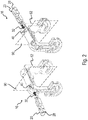
- Fig. 2 to 4 show a pre-mounting of parts of the CPA device 16. Fig. 1 to 4 are therefore described in the following together wherein each of the figures is addressed accordingly.
- Fig. 2 to 4 show a pre-mounting of a CPA device 16, wherein in this embodiment of a connector assembly 10 of the invention as shown in Fig. 5 to 7 , a bearing portion 40 of the CPA device 16 is provided in a lever 62 of the connector assembly 10.
- this bearing portion 40 the CPA element 20 can be inserted, whereby the CPA element 20 is movably supported, especially longitudinally movably supported, in the bearing portion 40.
- the CPA element 20 is provided as a slider.
- the CPA element 20 and the bearing portion 40 may be constructed such, that the CPA element 20 can be inserted into the bearing portion 40 at both ends in a first direction 30 and an opposite second direction 32, respectively.
- This can easily be provided by constructing the CPA element 20, at least with respect to the assurance section 22, the bearing portion 40 and the CPA counter portion 50, at least with respect to the assurance surface 54, with a mirror symmetry in respect to a mirror plane 90 perpendicular to the first direction 30 and the second direction 32.
- the CPA element 20 can be constructed such, that the CPA element 20 can also be inserted into the bearing portion 40 in a state where it is rotated by 180° around the first direction 30, in other words when the CPA element 20 is flipped upside down.
- the CPA element 20 comprises an opening 86 delimited by a peripheral frame 88 and a flexible rod section 80 extending into this opening 86.
- the flexible rod section 80 comprises a shaft portion 82 and a head portion 84 arranged at an end of the shaft portion 82 positioned in the opening 86, wherein the operation element 24 is arranged at the head portion 84.
- the head portion 84 can be formed at least essentially with a triangular shape with a base of the triangle forming the operation element 24 and the two legs of the triangle smoothly connect the operation element 24 to the shaft portion 82 of the flexible rod section 80.
- the assurance section 22 is at least partly arranged at the peripheral frame 88 to provide an especially compact design of the CPA element 20.
- Fig. 3 shows a second step of a pre-mounting of such a CPA device 16, whereby the CPA element 20 is already inserted into the bearing portion 40 along the first direction 30.
- the operation element 24 of the CPA element 20 constructed on the head section 84 of the flexible rod section 80 of the CPA element 20 engages a guiding surface 48, which is part of a retaining element 44 of the bearing portion 40.
- the retaining element 44 shown in Fig. 3 is provided on this position of the bearing portion 40 for an insertion of the CPA element 20 into the bearing portion 40 along the second direction 32. Therefore, the retaining element 44 shown in Fig. 3 is actually unused.
- a guiding surface 48 facing the first direction 30 and additionally tilted with respect to the first direction 30 is provided on the retaining element 44.
- the shaft portion 82 of the flexible rod section 80 preferably is formed smaller with respect to a direction perpendicular to the first direction 30 as the head portion 84, the flexible rod section 80 can return to its normal and non-displaced state after a passing of the head portion 84 of this currently unused retaining element 44.
- a recess 42 of the bearing portion 40 which later on can receive a protrusion 52 of a CPA counter portion 50 (both not shown).
- Fig. 4 shows the final stage of the pre-mounting of the CPA device 16, in which the CPA element 20 is finally mounted in its unblocking position 34.
- the CPA element 20 comprises a pre-lock element 26, see Fig. 1 , which can engage a pre-lock section 46 of the bearing portion 40 in a form fitting way, see especially the upper insert of Fig. 4 .
- This form fit secures the CPA element 20 in the bearing portion 40 and prevents a movement of the CPA element 20 against the first direction 30 out of the bearing portion 40.
- An accidental removing of the CPA element 20 after finishing the pre-mounting of the CPA device 16 can therefore be provided.
- Fig. 5 to 7 show a connector assembly 10 during three steps of an activation of the CPA device 16 of the connector assembly 10 as described above with respect to Fig. 2 to 4 .
- the Figs. 5 to 7 are therefore described together in the following.
- the CPA device 16 is constructed as described above with respect to Fig. 1 to 4 .
- the connector assembly 10 comprises a first connector 60 and a second connector 70, which comprise an interface 18 for the possible usage of the connector assembly 10 in a safety related system 100, for instance an airbag system.
- the second connector 70 is formed as a cover of the connector assembly 10.
- the first connector 60 and the second connector 70 are already connected, wherein the first connector 60 comprises a lever 62 in its release position 64 and the second connector 70 comprises a receiving means 72 for receiving this lever 62.
- a CPA element 20 of the CPA device 16 is already pre-mounted in a bearing portion 40 located in the lever 62.
- the receiving means 72 comprises two protrusions 52, both of them comprising an assurance surface 54 and an activation element 56 positioned on opposite sides of the respective protrusion 52.
- the second connector 70 comprises a primary locking mechanism 12, constructed as a latching mechanism 14 to secure the lever 62 in its fixation position 66, as shown in Fig. 6 and 7 .
- Fig. 6 shows the connector assembly 10 directly after moving the lever 62 in its fixation position 66.
- the CPA element 20 is positioned still in its unblocking position 34. Nevertheless, as shown in the insert in Fig. 6 , the protrusion 52 is already received in the recess 42, whereby the activation element 56 as part of the protrusion 52 engages the operation element 24 of the CPA element 20, thereby deforming the flexible rod section 80 and braking the form fit between the operation element 24 and the retaining element 44 of the bearing portion 40. This allows a further movement of the CPA element 20 along the first direction 30.
- Fig. 7 The result of such a movement of the CPA element 20 out of its unblocking position 34 in its blocking position 36 is shown in Fig. 7 .
- protrusions 52 are received by recesses 42 of the bearing portion 40, whereby each of the two protrusions 52 comprises assurance surfaces 54 arranged on opposite sides of the protrusion 52 as the deactivation elements 56.
- the movement of the CPA element 20 into its blocking position 36 results in engaging behind of the assurance surfaces 54 of the CPA counter portion 50 by the assurance sections 22 of the CPA element 20.
- This form fit securely fixes the lever 62 in its fixation position 66.
- Providing at least two assurance surfaces 54 and respective assurance sections 22 allows distributing the force needed to provide the form fit between the CPA element 20 and the CPA counter portion 50.
- fixation of the lever 62 provided by the CPA element 20 of the CPA device 16 is separate and independent of the locking of the primary locking mechanism 12. An overall safe guarding of a connector assembly 10 according to the invention against failure can therefore be improved. Even if the primary locking mechanism 12 fails, the CPA device 16 stays functional and therefore a continuation of the security against disconnecting can be provided.
Landscapes
- Details Of Connecting Devices For Male And Female Coupling (AREA)
Abstract
Description
- The present invention relates to a connector assembly for a safety related system, comprising a first connector and a second connector connectable to each other, wherein the first connector comprises a lever movably mounted to the first connector and a second connector comprises a receiving means for receiving the lever, wherein the lever is moveable at least between a release position and a fixation position, whereby connecting and releasing of the first connector and the second connector is possible with the lever in its release position and prohibited with the lever in its fixation position by a form fit between the lever and the receiving means, the connector assembly further comprising a primary locking mechanism and an additional connector position assurance (CPA) device, both for securing the lever in its fixation position.
- Connector assemblies are commonly used to provide connections of different types, for instance for connecting power lines and data cables. Such connector assemblies can for instance be used in vehicles like cars, ships and/or airplanes. Especially in safety related systems, for instance vehicle airbag systems, disconnection of connector assemblies has to be prohibited.
- To prevent an accidental disconnection of the connectors of a connector assembly it is known to use a lever, moveably mounted on one of the connectors and configured to engage the other connector in a form fitting way. Hence, securing the two connectors to each other can be provided by the lever in a respective fixation position. Additionally, a locking mechanism can be provided to hold the lever in this fixation position. Further, an additional connector position assurance (CPA) device can be provided to ensure a proper function of the locking mechanism.
- In view of the above, it is an object of the present invention to provide a connector assembly for a safety related system, which provides an increased safe guarding against a failure and/or an accidental disconnecting of the connector assembly and which preferably are easy to handle.
- This object is satisfied by a connector assembly for a safety related system according to claim 1. The dependent claims describe preferred embodiments of the invention.
- The connector assembly of the invention comprises a first connector and a second connector connectable to each other, wherein the first connector comprises a lever moveably mounted to the connector and the second connector comprises a receiving means for receiving the lever, wherein the lever is movable at least between a release position and a fixation position, whereby connecting and releasing of the first connector and the second connector is possible with the lever in its release position and prohibited with the lever in its fixation position by a form fit between the lever and the receiving means, the connector assembly further comprising a primary locking mechanism and an additional connector position assurance (CPA) device, both for securing the lever and its fixation position. A connector assembly according to the invention is characterized in that the CPA device is separate and independent from the primary locking mechanism.
- The connector assembly of the invention can be used to connect power lines and data cables, especially for and/or in safety related systems. Preferably, the connector assembly is part and/or can be used in a safety related system of a vehicle, for instance a car, a ship or a plane. Such safety related systems can be for instance an airbag system of the vehicle.
- In the connector assembly one of the connectors can be formed as a male connector, the other one as a female connector. Additionally or alternatively, one of the connectors can be formed as a cover of the connector assembly, whereby the actual connection functionality is, preferably is exclusively provided by the other connector. The first connector comprises a lever, which is moveably mounted to this first connector, preferably pivotably mounted to the first connector. Accordingly, the second connector comprises a receiving means for receiving this lever. In a connected state of the first connector and the second connector, the lever can be moved in its fixation position wherein it is received by the receiving means of the second connector. In this fixation position, the lever and the receiving means of the second connector form a form fit and hence a disconnection, especially an accidental disconnection, of the two connectors can be prevented.
- Additionally, the lever can be moved into a release position, in which the form fit of the lever and the receiving means is lifted and hence disconnecting the two connectors is rendered possible.
- Further, the connector assembly according to the invention comprises a primary locking mechanism and an additional connector position assurance (CPA) device for securing the lever in its fixation position. Preferably, the primary locking mechanism can be formed as a latching mechanism. By securing the lever in its fixation position, an accidental movement of the lever out of its fixation position can be prohibited and therefore a failure of the connector assembly, especially disconnecting the first and second connector of the connector assembly, can be prohibited.
- According to the invention, the CPA device is separate and independent from the primary locking mechanism. In other words, both the primary locking mechanism and the CPA device are positioned at different locations and/or sections of the connector assembly according to the invention. Therefore they provide securing a remaining of the lever in its fixation position in different and especially independent modes of operations. Therefore, even if the primary locking mechanism fails, the separate and independent CPA device stays functional. A gain in safe guarding against a failure of the connector assembly can therefore be improved. Hence, a connector assembly according to the invention can provide a higher security against disconnecting of the first connector and the second connector.
- According to an embodiment, the CPA device comprises a movable CPA element, a bearing portion for bearing the CPA element and a CPA counter portion, wherein an interaction between the CPA element and the CPA counter portion provides the securing of the lever in its fixation position, whereby the lever comprises the bearing portion and the receiving means comprises the CPA counter portion or whereby the receiving means and comprises the bearing portion and the lever comprises the CPA counter portion. Providing a movable CPA element, movably, preferably slidably, supported in the bearing portion, provides an especially easy way to turn on and/or off the function of the CPA device with respect to securing the functionality of the connector assembly according to the invention.
- Further, the bearing portion and the CPA counter portion preferably are assigned and accordingly located on different connectors of the connector assembly according to the invention. Hereby both possibilities can be realized, on the one hand a bearing portion as part of the lever of the first connector and the CPA counter portion as part of the receiving means of the second connector and on the other hand the bearing portion as part of the receiving means of the second connector and the CPA counter portion as part of the lever of the first connector. Both arrangements allow providing a form fit between the CPA element supported in the bearing portion and the CPA counter portion in an especially easy way. This form fit secures in both possible arrangements that the lever stays in its fixation position and therefore that the two connectors of the connector assembly stay connected.
- According to a preferred embodiment, the CPA element is slidably supported in the bearing portion and slidable in a first direction between an unblocking position and a blocking position, whereby with the CPA element in its unblocking position a movement of the lever is possible and the lever in its fixation position and simultaneously with the CPA element in its blocking position, the lever is blocked in its fixation position by a form fit between an assurance section of the CPA element and an assurance surface of the CPA counter portion and by a form fit provided by supporting of the CPA element in the bearing portion, respectively. In this preferred embodiment of a connector assembly according to the invention, the CPA element is formed as slider, moveably, especially slidably, supported in the bearing portion. In other words, the CPA element is especially longitudinally movably supported in the bearing portion. In the unblocking position, a movement of the lever is not hindered by the CPA element. In contrast to that and with a CPA element in its blocking position and simultaneously with a lever in its fixation position, a form fit between the CPA element and the CPA counter portion provides a secure locking of the lever in its fixation position. Especially, the aforementioned form fit is provided between an assurance section of the CPA element and an assurance surface of the CPA counter portion. This embodiment allows an especially easy way to active and deactivate the CPA device of the connector assembly according to the invention, simply by moving the CPA element between its blocking and unblocking position.
- Further, the CPA element may comprise at least two assurance sections and/or the CPA counter portion comprises at least two assurance surfaces. By providing at least two assurance sections and/or two assurance surfaces a further gain in security of a locking of the lever in its fixation position can be provided. Especially when a form fit is used between the CPA element and the CPA counter portion, providing at least two assurance sections and/or two assurance surfaces allows distributing the force needed to provide the form fit between the CPA element and the CPA counter portion and hence to hold the CPA element in place. Therefore less stress on the components involved in the form fit can be provided. Additionally, the CPA element may comprise an operation element, the bearing portion comprises a retaining element and the CPA counter portion comprises an activation element, wherein with the lever away from its fixation position the retaining element blocks a movement of the CPA element from its unblocking position into its blocking position by form fittingly contacting the operation element, and wherein with the lever in its fixation position the activation element contacts the operation element and brakes the form fit between the operation element and the retaining element to enable a movement of the CPA element from its unblocking position into its blocking position. In this embodiment of a connector assembly according to the invention, a movement of the CPA element into its blocking position is prohibited unless the lever is in its fixation position. In other words, a movement of the CPA element from its unblocking position in its blocking position is only possible, when the lever is positioned in its fixation position. The aforementioned form fit between the CPA element and the CPA counter portion to fixate the lever in its fixation position often includes engaging of a part of the CPA element behind a part of the CPA counter portion, for instance of the assurance section of the CPA element and the assurance surface of the CPA counter portion. If the CPA element is moved into its blocking position when the lever is outside of its fixation position, also the part of the CPA element providing this engaging behind, especially the assurance section, is moved into its engaging position. This may block the way of the respective part of the CPA counter portion and hence prevent moving the lever in its fixation position. Therefore blocking the movement of the CPA element from its unblocking position into its blocking position unless the lever in its fixation position prevents this unfortunate situation.
- In an enhanced embodiment, the CPA element comprises an opening delimited by a peripheral frame and a flexible rod section extending into the opening, wherein the flexible rod section comprises a shaft portion and a head portion arranged at an end of the shaft portion positioned in the opening, and wherein the operation element is arranged at the head portion, and in particular wherein the assurance section is at least partly arranged at the peripheral frame. In other words, the operation element is at least partly movably arranged in the opening within the CPA element. This movability can be provided by the flexible rod section, in particular by the shaft portion of the flexible rod section. Preferably, one end of the flexible rod section is fixed to a body portion of the CPA element, preferably is formed integrally with the body portion of the CPA element, the other end of the flexible rod section forms the head portion comprising the operation element. In summary, this embodiment allows to break the form fit between the operation element and the retaining element by the activation element in an especially easy way, simply by contacting and successively displacing the flexible rod section, in particular the shaft portion of the flexible rod section, with the activation element. Therefore, complex and hence costly means for an activation of the CPA element can be avoided. An at least partly arrangement of the assurance section at the peripheral frame can provide an especially compact design of the CPA element. Additionally, the head portion can be formed at least essentially in a triangular shape with a base of the triangle forming the operation element and the two legs of the triangle smoothly connect the operation element to the shaft portion of the flexible rod section. Hence, if the CPA element is removed from the bearing portion, the legs of the triangular head section can avoid that the head section and especially the operation element is getting caught in the bearing portion.
- According to a further embodiment, the CPA element, at least with respect to the assurance section and the operation element, is symmetric with respect to 180° rotation around the first direction. In other words, the CPA element is at least with respect to the assurance section and the operation element symmetrically independent, whether the CPA element is normal orientated or upside down orientated. Mounting the CPA element into the bearing portion is therefore possible in both ways and/or both orientations of the CPA element, respectively, whereby a handling and/or mounting of the CPA element and therefore of the connector assembly according to the invention as a whole can be simplified.
- In another preferred embodiment, the CPA element, at least with respect to the assurance section, the bearing portion and the CPA counter portion, at least with respect to the assurance surface, are all mirror symmetric in respect to a mirror plane perpendicular to the first direction for allowing an assembly of the CPA by moving the CPA element in a second direction opposite to the first direction. In other words, the CPA element, the bearing portion and the CPA counter portion are constructed such that the bearing portion is open on both ends and the CPA element can be inserted into the bearing portion at both ends of the bearing portion. Therefore, a further simplification of an assembly of a connector assembly according to the invention can be provided.
- In particular, the bearing portion comprises two retaining elements arranged apart from each other along the first direction and the second direction, each retaining element comprising a guiding surface, wherein the respective guiding surface is tilted in respect to the first direction and the second direction, respectively, and faces away from the mirror plane to deflect the head portion of the flexible rod section during an insertion of the CPA element in the bearing portion. In this embodiment, the CPA element can be inserted into the bearing portion both in the first direction and in the second direction at respective ends of the bearing portion. For each case, only the retaining element farther from the end of the bearing portion used for the insertion of the CPA element is in operation as actual retaining element, the other retaining element remains unused. To avoid a blocking of a movement of the CPA element in the bearing portion by the currently unused retaining element, the retaining elements comprise guiding surfaces tilted in respect to the first and second direction. The head portion of the flexible rod section at first contacts this guiding surface and is easily deflected by its tilted form. As the shaft portion of the flexible rod section preferably is formed smaller with respect to a direction perpendicular to the first and second direction as the head portion, the flexible rod section can return to its normal and non-displaced state after a passing of the head portion of the currently unused retaining element by the head portion. Therefore contacting the operation element on the head portion of the flexible rod section by the second and active retaining element can easily be provided.
- Additionally, a connector assembly according to the invention can be constructed such that the assurance surface and/or the activation element of the CPA counter portion are formed as and/or on at least one protrusion. For instance in the embodiment in which the CPA counter portion is constructed as part of the receiving means, the remaining parts of the receiving means can be constructed generally flat for the receiving of the lever and the assurance surface and/or the activation element can be provided as and/or at least one protrusion projected out of this flat surface. Hence a protrusion is in this case an especially easy way to provide the specialized parts of the receiving means forming the CPA counter portion, especially the assurance surface and/or the activation element of the CPA counter portion.
- According to a further improved embodiment of a connector assembly according to the invention, the assurance surface and the activation element of the CPA counter portion are formed on different, in particular opposite, sides of the same protrusion. This allows using the same protrusion to provide both the assurance surface and deactivation element, respectively. Hence a connector assembly according to the invention can further be simplified, as no separate elements for providing both the assurance surface and the activation element, respectively, are needed.
- Additionally, a connector assembly according to the invention can be improved by that the bearing portion comprises at least one recess to receive the at least one protrusion when the lever is in its fixation position. In other words, the at least one protrusion can be placed in the at least one recess when the lever is moved in its fixation position. An interaction between the assurance surface and/or the activation element formed as and/or on the at least one protrusion with the CPA element beard in the bearing portion can therefore be provided especially easily. The recesses of the bearing portion receives the protrusion, the CPA element is moved within the bearing portion and therefore can easily engage behind the protrusion and hence provide the form fit for locking the lever in its fixation position. In addition, providing a recess to receive the at least one protrusion allows providing the CPA device as a whole in an especially compact way.
- Further, the CPA element may comprise a pre-lock element and the bearing portion may comprise a pre-lock section, wherein the pre-lock section contacts the pre-lock element in a form fitting way to prevent a movement of the CPA element against the first direction, when the CPA element is in its unblocking position. In other words, when the CPA element is inserted into the bearing portion at a certain point of the movement the pre-lock element of the CPA element engages the pre-lock section of the bearing portion. Hereby for instance the pre-lock element of the CPA element can be provided as protrusion of the CPA element and the pre-lock section of the bearing portion can be provided as a recess and vice versa. The engagement of the pre-lock section by the pre-lock element secures a CPA element in the bearing portion such, that an accidental removing of the CPA element from the bearing portion can be prohibited. A pre-mounting of the CPA element in the bearing portion can therefore be provided in a secure way. If the aforementioned embodiment is realized, in which a mounting of the CPA element into the bearing portion is also possible in a second direction, the CPA device can comprise additionally pre-lock elements and respective pre-lock sections to provide the advantages described above also for a mounting of the CPA element in the second direction.
- In addition the CPA element may comprise a grip element for a manual movement of the CPA element from its unblocking position into its blocking position, in particular wherein the grip element is accessible from outside of the bearing portion independent of the actual position of the CPA element. A grip element can for instance be formed as a special section of the CPA element, preferably at one of the ends of the CPA element. This special embodiment of the connector assembly allows an especially easily handling, whereby the movement of the CPA element can be provided without the need for a tool, especially for a special tool. Preferably, the CPA element can be moved manually via the grip element in both directions, from its unblocking position into its blocking position and vice versa. This can especially easily be provided by a grip element accessible from outside of the bearing portion independent of the actual position of the CPA element.
- In an especially preferred embodiment of a connector assembly according to the invention, the connector assembly comprises an interface for an assembly in a safety related system of a vehicle, in particular an airbag system of the vehicle. Such an interface can for instance be formed as a cable inlet and/or outlet or as mounting parts and/or sections accordingly constructed to counterparts and/or sections of the safety related system. A usage of a connector assembly according to the invention in a safety related system can therefore be provided in an especially easy way.
- In particular, a safety related system can comprise a connector assembly as discussed above. Therefore a safety related system comprising a connector assembly of the invention has all the features and advantages described above in detail with respect to the connector assembly of the invention.
- The safety related system may be an airbag system. With the connector assembly of the invention, a malfunction of the airbag system caused by an accidental disconnection of the connector assembly can therefore be prohibited or at least be rendered improbable.
- The present invention is further described hereinafter with reference to an illustrate embodiment shown in the accompanying drawings.
- There is shown:
- Fig. 1
- a CPA element of a CPA device,
- Fig. 2
- a first mounting step of a CPA device,
- Fig. 3
- a second mounting step of a CPA device,
- Fig. 4
- a third mounting step of a CPA device,
- Fig. 5
- a connector assembly with a lever in its release position,
- Fig. 6
- a connector assembly with a lever in its fixation position and an activation of the CPA element, and
- Fig. 7
- a connector assembly with an activated CPA device securing the lever in its fixation position.
- In
Fig. 1 aCPA element 20 is shown which can be used in aCPA device 16 as shown in the followingFigs. 2 to 7 .Fig. 2 to 4 show a pre-mounting of parts of theCPA device 16.Fig. 1 to 4 are therefore described in the following together wherein each of the figures is addressed accordingly. -
Fig. 2 to 4 show a pre-mounting of aCPA device 16, wherein in this embodiment of a connector assembly 10 of the invention as shown inFig. 5 to 7 , a bearingportion 40 of theCPA device 16 is provided in alever 62 of the connector assembly 10. In this bearingportion 40 theCPA element 20 can be inserted, whereby theCPA element 20 is movably supported, especially longitudinally movably supported, in the bearingportion 40. In other words, theCPA element 20 is provided as a slider. - As shown in
Fig. 2 , theCPA element 20 and the bearingportion 40 may be constructed such, that theCPA element 20 can be inserted into the bearingportion 40 at both ends in afirst direction 30 and an oppositesecond direction 32, respectively. This can easily be provided by constructing theCPA element 20, at least with respect to theassurance section 22, the bearingportion 40 and theCPA counter portion 50, at least with respect to theassurance surface 54, with a mirror symmetry in respect to amirror plane 90 perpendicular to thefirst direction 30 and thesecond direction 32. Additionally, theCPA element 20 can be constructed such, that theCPA element 20 can also be inserted into the bearingportion 40 in a state where it is rotated by 180° around thefirst direction 30, in other words when theCPA element 20 is flipped upside down. - As depicted in
Fig. 1 , theCPA element 20 comprises an opening 86 delimited by aperipheral frame 88 and aflexible rod section 80 extending into this opening 86. Theflexible rod section 80 comprises ashaft portion 82 and ahead portion 84 arranged at an end of theshaft portion 82 positioned in the opening 86, wherein theoperation element 24 is arranged at thehead portion 84. Especially, thehead portion 84 can be formed at least essentially with a triangular shape with a base of the triangle forming theoperation element 24 and the two legs of the triangle smoothly connect theoperation element 24 to theshaft portion 82 of theflexible rod section 80. Further, theassurance section 22 is at least partly arranged at theperipheral frame 88 to provide an especially compact design of theCPA element 20. -
Fig. 3 shows a second step of a pre-mounting of such aCPA device 16, whereby theCPA element 20 is already inserted into the bearingportion 40 along thefirst direction 30. In this step theoperation element 24 of theCPA element 20 constructed on thehead section 84 of theflexible rod section 80 of theCPA element 20, engages a guidingsurface 48, which is part of a retainingelement 44 of the bearingportion 40. The retainingelement 44 shown inFig. 3 is provided on this position of the bearingportion 40 for an insertion of theCPA element 20 into the bearingportion 40 along thesecond direction 32. Therefore, the retainingelement 44 shown inFig. 3 is actually unused. To avoid a blocking of the movement of theCPA element 20 along thefirst direction 30, a guidingsurface 48 facing thefirst direction 30 and additionally tilted with respect to thefirst direction 30 is provided on the retainingelement 44. During a movement of theCPU element 20 in the bearing portion 40along thefirst direction 30, thehead portion 84 of theflexible rod section 80 at first contacts this guidingsurface 48 and is easily deflected by its tilted form. As theshaft portion 82 of theflexible rod section 80 preferably is formed smaller with respect to a direction perpendicular to thefirst direction 30 as thehead portion 84, theflexible rod section 80 can return to its normal and non-displaced state after a passing of thehead portion 84 of this currently unused retainingelement 44. Also visible inFig. 3 is arecess 42 of the bearingportion 40 which later on can receive aprotrusion 52 of a CPA counter portion 50 (both not shown). -
Fig. 4 shows the final stage of the pre-mounting of theCPA device 16, in which theCPA element 20 is finally mounted in its unblocking position 34. In this preferred embodiment, theCPA element 20 comprises apre-lock element 26, seeFig. 1 , which can engage apre-lock section 46 of the bearingportion 40 in a form fitting way, see especially the upper insert ofFig. 4 . This form fit secures theCPA element 20 in the bearingportion 40 and prevents a movement of theCPA element 20 against thefirst direction 30 out of the bearingportion 40. An accidental removing of theCPA element 20 after finishing the pre-mounting of theCPA device 16 can therefore be provided. - In the second insert in
Fig. 4 the interaction between theoperation element 24 and the respective active retainingelement 44 of the bearingportion 40 is shown. Also theoperation element 24 and the retaining 44 form a form fit such, that a further movement of theCPA element 20, for instance caused by manual engaging thegrip element 28 of theCPA element 20 is blocked. A blocking of therecess 42, also shown in this insert inFig. 4 , by theassurance section 22 of theCPA element 20 can be therefore prohibited. This allows an undisturbed movement of thelever 62, in which the bearingportion 40 is located, out of its release position 64 into its fixation position 66 (both not shown). -
Fig. 5 to 7 show a connector assembly 10 during three steps of an activation of theCPA device 16 of the connector assembly 10 as described above with respect toFig. 2 to 4 . TheFigs. 5 to 7 are therefore described together in the following. TheCPA device 16 is constructed as described above with respect toFig. 1 to 4 . - The connector assembly 10 comprises a
first connector 60 and asecond connector 70, which comprise aninterface 18 for the possible usage of the connector assembly 10 in a safety relatedsystem 100, for instance an airbag system. In the embodiment shown thesecond connector 70 is formed as a cover of the connector assembly 10. - In
Fig. 5 thefirst connector 60 and thesecond connector 70 are already connected, wherein thefirst connector 60 comprises alever 62 in its release position 64 and thesecond connector 70 comprises a receiving means 72 for receiving thislever 62. ACPA element 20 of theCPA device 16 is already pre-mounted in a bearingportion 40 located in thelever 62. The receiving means 72 comprises twoprotrusions 52, both of them comprising anassurance surface 54 and anactivation element 56 positioned on opposite sides of therespective protrusion 52. Further, thesecond connector 70 comprises a primary locking mechanism 12, constructed as a latching mechanism 14 to secure thelever 62 in its fixation position 66, as shown inFig. 6 and7 . -
Fig. 6 shows the connector assembly 10 directly after moving thelever 62 in its fixation position 66. TheCPA element 20 is positioned still in its unblocking position 34. Nevertheless, as shown in the insert inFig. 6 , theprotrusion 52 is already received in therecess 42, whereby theactivation element 56 as part of theprotrusion 52 engages theoperation element 24 of theCPA element 20, thereby deforming theflexible rod section 80 and braking the form fit between theoperation element 24 and the retainingelement 44 of the bearingportion 40. This allows a further movement of theCPA element 20 along thefirst direction 30. - The result of such a movement of the
CPA element 20 out of its unblocking position 34 in its blocking position 36 is shown inFig. 7 . As shown in the insert inFig. 7 ,protrusions 52 are received byrecesses 42 of the bearingportion 40, whereby each of the twoprotrusions 52 comprises assurance surfaces 54 arranged on opposite sides of theprotrusion 52 as thedeactivation elements 56. The movement of theCPA element 20 into its blocking position 36 results in engaging behind of the assurance surfaces 54 of theCPA counter portion 50 by theassurance sections 22 of theCPA element 20. This form fit securely fixes thelever 62 in its fixation position 66. Providing at least two assurance surfaces 54 andrespective assurance sections 22 allows distributing the force needed to provide the form fit between theCPA element 20 and theCPA counter portion 50. - Additionally, the fixation of the
lever 62 provided by theCPA element 20 of theCPA device 16 is separate and independent of the locking of the primary locking mechanism 12. An overall safe guarding of a connector assembly 10 according to the invention against failure can therefore be improved. Even if the primary locking mechanism 12 fails, theCPA device 16 stays functional and therefore a continuation of the security against disconnecting can be provided. -
- 10
- connector assembly
- 12
- primary locking mechanism
- 14
- latching mechanism
- 16
- CPA device
- 18
- interface
- 20
- CPA element
- 22
- assurance section
- 24
- operation element
- 26
- pre-lock element
- 28
- grip element
- 30
- first direction
- 32
- second direction
- 34
- unblocking position
- 36
- blocking position
- 40
- bearing portion
- 42
- recess
- 44
- retaining element
- 46
- pre-lock section
- 48
- guiding surface
- 50
- CPA counter portion
- 52
- protrusion
- 54
- assurance surface
- 56
- activation element
- 60
- first connector
- 62
- lever
- 64
- release position
- 66
- fixation position
- 70
- second connector
- 72
- receiving means
- 80
- rod section
- 82
- shaft portion
- 84
- head portion
- 86
- opening
- 88
- frame
- 90
- mirror plane
- 100
- safety related system
Claims (15)
- Connector assembly (10) for a safety related system (100), comprising a first connector (60) and a second connector (70) connectable to each other,
wherein the first connector (60) comprises a lever (62) movably mounted to the first connector (60) and the second connector (70) comprises a receiving means (72) for receiving the lever (62), wherein the lever (62) is movable at least between a release position (64) and a fixation position (66), whereby connecting and releasing of the first connector (60) and the second connector (70) is possible with the lever (62) in its release position (64) and prohibited with the lever (62) in its fixation position (66) by a form fit between the lever (62) and the receiving means (72),
the connector assembly (10) further comprising a primary locking mechanism (12) and an additional connector position assurance (CPA) device (16), both for securing the lever (62) in its fixation position (66),
characterized in that
the CPA device (16) is separate and independent from the primary locking mechanism (12). - Connector assembly (10) according to claim 1,
characterized in that
the CPA device (16) comprises a movable CPA element (20), a bearing portion (40) for bearing the CPA element (20) and a CPA counter portion (50),
wherein an interaction between the CPA element (20) and the CPA counter portion (50) provides the securing of the lever (62) in its fixation position (66),
whereby the lever (62) comprises the bearing portion (40) and the receiving means (72) comprises the CPA counter portion (50) or whereby the receiving means (72) comprises the bearing portion (40) and the lever (62) comprises the CPA counter portion (50). - Connector assembly (10) according to claim 2,
characterized in that
the CPA element (20) is slidably supported in the bearing portion (40) and slidable in a first direction (30) between an unblocking position (34) and a blocking position (36), whereby with the CPA element (20) in its unblocking position (34) a movement of the lever (62) is possible, and with the lever (62) in its fixation position (66) and simultaneously with the CPA element (20) in its blocking position (36), the lever (62) is locked in its fixation position (66) by a form fit between an assurance section (22) of the CPA element (20) and an assurance surface (54) of the CPA counter portion (50) and by a form fit provided by supporting of the CPA element (20) in the bearing portion (40), respectively. - Connector assembly (10) according to claim 2 or 3,
characterized in that
the CPA element (20) comprises at least two assurance sections (22) and/or the CPA counter portion (50) comprises at least two assurance surfaces (54). - Connector assembly (10) according to one of the claims 2 to 4,
characterized in that
the CPA element (20) comprises an operation element (24), the bearing portion (40) comprises a retaining element (44) and the CPA counter portion (50) comprises an activation element (56), wherein with the lever (62) away from its fixation position (66) the retaining element (44) blocks a movement of the CPA element (20) from its unblocking position (34) into its blocking position (36) by form fittingly contacting the operation element (24), and wherein with the lever (62) in its fixation position (66) the activation element (56) contacts the operation element (24) and breaks the form fit between the operation element (24) and the retaining element (44) to enable a movement of the CPA element (20) from its unblocking position (34) into its blocking position (36). - Connector assembly (10) according to claim 5,
characterized in that
the CPA element (20) comprises an opening (86) delimited by a peripheral frame (88) and a flexible rod section (80) extending into the opening (86), wherein the flexible rod section (80) comprises a shaft portion (82) and a head portion (84) arranged at an end of the shaft portion (82) positioned in the opening (86), and wherein the operation element (24) is arranged at the head portion (84), and in particular wherein the assurance section (22) is at least partly arranged at the peripheral frame (88). - Connector assembly (10) according to one of the claims 2 to 6,
characterized in that
the CPA element (20), at least with respect to the assurance section (22) and the operation element (24), is symmetric with respect to a 180° rotation around the first direction (30). - Connector assembly (10) according to one of the claims 2 to 7,
characterized in that
the CPA element (20) at least with respect to the assurance section (22),
the bearing portion (40), and
the CPA counter portion (50) at least with respect to the assurance surface (54),
are all mirror symmetric in respect to a mirror plane (90) perpendicular to the first direction (30) for allowing an assembly of the CPA device (16) by moving the CPA element (20) in a second direction (32) opposite to the first direction (30). - Connector assembly (10) according to one of the claims 5 to 7 in combination with claim 8,
characterized in that
the bearing portion (40) comprises two retaining elements (44) arranged apart from each other along the first direction (30) and the second direction (32), each retaining element (44) comprising a guiding surface (48), wherein the respective guiding surface (48) is tilted in respect to the first direction (30) and the second direction (32), respectively, and faces away from the mirror plane (90) to deflect the head portion (84) of the flexible rod section (80) during an insertion of the CPA element (20) in the bearing portion (40). - Connector assembly (10) according to one of the claims 2 to 9,
characterized in that
the assurance surface (54) and/or the activation element (56) of the CPA counter portion (50) are formed as and/or on at least one protrusion. - Connector assembly (10) according to claim 10,
characterized in that
the assurance surface (54) and the activation element (56) of the CPA counter portion (50) are formed on different, in particular opposite, sides of the same protrusion. - Connector assembly (10) according to claim 10 or 11,
characterized in that
the bearing portion (40) comprises at least one recess (42) to receive the at least one protrusion (52) when the lever (62) is in its fixation position (66). - Connector assembly (10) according to one of the claims 2 to 12,
characterized in that
the CPA element (20) comprises a pre-lock element (26) and the bearing portion (40) comprises a pre-lock section (46), wherein the pre-lock section (46) contacts the pre-lock element (26) in a form fitting way to prevent a movement of the CPA element (20) against the first direction (30), when the CPA element (20) is in its unblocking position (34). - Connector assembly (10) according to one of the claims 2 to 13,
characterized in that
the CPA element (20) comprises a grip element (28) for a manual movement of the CPA element (20) from its unblocking position (34) into its blocking position (36), in particular wherein the grip element (28) is accessible from outside of the bearing portion (40) independent of the actual position of the CPA element (20). - Connector assembly (10) according to one of the preceding claims,
characterized in that
the connector assembly (10) comprises an interface (18) for an assembly in a safety related system (100) of a vehicle, in particular an airbag system of the vehicle.
Priority Applications (1)
| Application Number | Priority Date | Filing Date | Title |
|---|---|---|---|
| EP19156364.2A EP3694058B1 (en) | 2019-02-11 | 2019-02-11 | Connector assembly for a safety related system |
Applications Claiming Priority (1)
| Application Number | Priority Date | Filing Date | Title |
|---|---|---|---|
| EP19156364.2A EP3694058B1 (en) | 2019-02-11 | 2019-02-11 | Connector assembly for a safety related system |
Publications (2)
| Publication Number | Publication Date |
|---|---|
| EP3694058A1 true EP3694058A1 (en) | 2020-08-12 |
| EP3694058B1 EP3694058B1 (en) | 2023-06-07 |
Family
ID=65408929
Family Applications (1)
| Application Number | Title | Priority Date | Filing Date |
|---|---|---|---|
| EP19156364.2A Active EP3694058B1 (en) | 2019-02-11 | 2019-02-11 | Connector assembly for a safety related system |
Country Status (1)
| Country | Link |
|---|---|
| EP (1) | EP3694058B1 (en) |
Cited By (3)
| Publication number | Priority date | Publication date | Assignee | Title |
|---|---|---|---|---|
| CN114628953A (en) * | 2020-12-10 | 2022-06-14 | 泰连德国有限公司 | Electrical plug device with releasable blocking mechanism for position assurance element |
| DE102022204731A1 (en) | 2022-05-13 | 2023-11-16 | Robert Bosch Gesellschaft mit beschränkter Haftung | Connector arrangement |
| JP2025010086A (en) * | 2023-07-06 | 2025-01-20 | ティーイー コネクティビティ インディア プライベート リミテッド | Connector Assembly |
Families Citing this family (1)
| Publication number | Priority date | Publication date | Assignee | Title |
|---|---|---|---|---|
| WO2025251312A1 (en) * | 2024-06-07 | 2025-12-11 | Robert Bosch Gmbh | Plug connector and plug connector assembly |
Citations (4)
| Publication number | Priority date | Publication date | Assignee | Title |
|---|---|---|---|---|
| US20060211286A1 (en) * | 2005-03-15 | 2006-09-21 | Shuey John R | Lever mated connector assembly with a position assurance device |
| EP2675021A2 (en) * | 2012-06-11 | 2013-12-18 | Delphi Technologies, Inc. | Electrical connection system including mating assist lever that contains locking means and connector position assurance member that interacts therewith |
| CN206004036U (en) * | 2016-09-14 | 2017-03-08 | 泰科电子(上海)有限公司 | Cylinder lever connecting rod, rod assembly and electric connector |
| US10135183B1 (en) * | 2017-10-20 | 2018-11-20 | Lear Corporation | Electrical connector with assist lever |
-
2019
- 2019-02-11 EP EP19156364.2A patent/EP3694058B1/en active Active
Patent Citations (4)
| Publication number | Priority date | Publication date | Assignee | Title |
|---|---|---|---|---|
| US20060211286A1 (en) * | 2005-03-15 | 2006-09-21 | Shuey John R | Lever mated connector assembly with a position assurance device |
| EP2675021A2 (en) * | 2012-06-11 | 2013-12-18 | Delphi Technologies, Inc. | Electrical connection system including mating assist lever that contains locking means and connector position assurance member that interacts therewith |
| CN206004036U (en) * | 2016-09-14 | 2017-03-08 | 泰科电子(上海)有限公司 | Cylinder lever connecting rod, rod assembly and electric connector |
| US10135183B1 (en) * | 2017-10-20 | 2018-11-20 | Lear Corporation | Electrical connector with assist lever |
Cited By (5)
| Publication number | Priority date | Publication date | Assignee | Title |
|---|---|---|---|---|
| CN114628953A (en) * | 2020-12-10 | 2022-06-14 | 泰连德国有限公司 | Electrical plug device with releasable blocking mechanism for position assurance element |
| CN114628953B (en) * | 2020-12-10 | 2024-03-12 | 泰连德国有限公司 | Electrical plug device with releasable blocking mechanism for position assurance element |
| US12046856B2 (en) | 2020-12-10 | 2024-07-23 | Te Connectivity Germany Gmbh | Electrical plug device with a blocking mechanism for a position assurance element which can be released by a mating housing |
| DE102022204731A1 (en) | 2022-05-13 | 2023-11-16 | Robert Bosch Gesellschaft mit beschränkter Haftung | Connector arrangement |
| JP2025010086A (en) * | 2023-07-06 | 2025-01-20 | ティーイー コネクティビティ インディア プライベート リミテッド | Connector Assembly |
Also Published As
| Publication number | Publication date |
|---|---|
| EP3694058B1 (en) | 2023-06-07 |
Similar Documents
| Publication | Publication Date | Title |
|---|---|---|
| EP3694058B1 (en) | Connector assembly for a safety related system | |
| EP1859513B2 (en) | Lever mated connector assembly with a position assurance device | |
| JP6664425B2 (en) | Electrical connector with terminal position assurance device | |
| US6824406B1 (en) | Electrical connector assembly | |
| EP3171459A1 (en) | Electrical connector with a terminal position assurance device | |
| JP5406297B2 (en) | Lock deflection device | |
| US10008805B2 (en) | Connector device | |
| JP2000509194A (en) | Connector with secondary latch and lateral cable outlet | |
| JP2007331748A (en) | Arm mounting device of wiper blade for windshield | |
| CN109698427B (en) | Electric connector with auxiliary handle | |
| CN112217024B (en) | Electrical terminal connector assembly with terminal lock | |
| US5807130A (en) | Two way electrical connector | |
| US20230105340A1 (en) | Connection Assembly and Connector with Rotatable Position Assurance | |
| JP2006339154A (en) | Connector having lock lever | |
| US6663157B1 (en) | Removable motor vehicle seat | |
| US5586903A (en) | Plug connector in which the cables are led out at an angle and with a releasable secondary lock | |
| US9595788B1 (en) | Electrical connector having a flexible latch actuated by a ramp on a release collar | |
| US7467958B2 (en) | Electrical connector having lever with protective shroud | |
| US10047888B2 (en) | Quick connector | |
| JP7460397B2 (en) | High voltage electrical connector with CPA assembled on slider | |
| JP2007515046A (en) | Device for locking the connector module in the module holder | |
| JPH08298160A (en) | Connector | |
| KR100927885B1 (en) | connector | |
| CN118539222A (en) | Plug connection system, plug connector and plug connection | |
| CN114256687B (en) | Electrical connector assembly having a mating lever and a connector position assurance member |
Legal Events
| Date | Code | Title | Description |
|---|---|---|---|
| PUAI | Public reference made under article 153(3) epc to a published international application that has entered the european phase |
Free format text: ORIGINAL CODE: 0009012 |
|
| STAA | Information on the status of an ep patent application or granted ep patent |
Free format text: STATUS: THE APPLICATION HAS BEEN PUBLISHED |
|
| AK | Designated contracting states |
Kind code of ref document: A1 Designated state(s): AL AT BE BG CH CY CZ DE DK EE ES FI FR GB GR HR HU IE IS IT LI LT LU LV MC MK MT NL NO PL PT RO RS SE SI SK SM TR |
|
| AX | Request for extension of the european patent |
Extension state: BA ME |
|
| STAA | Information on the status of an ep patent application or granted ep patent |
Free format text: STATUS: REQUEST FOR EXAMINATION WAS MADE |
|
| 17P | Request for examination filed |
Effective date: 20210210 |
|
| RBV | Designated contracting states (corrected) |
Designated state(s): AL AT BE BG CH CY CZ DE DK EE ES FI FR GB GR HR HU IE IS IT LI LT LU LV MC MK MT NL NO PL PT RO RS SE SI SK SM TR |
|
| STAA | Information on the status of an ep patent application or granted ep patent |
Free format text: STATUS: EXAMINATION IS IN PROGRESS |
|
| 17Q | First examination report despatched |
Effective date: 20210920 |
|
| GRAP | Despatch of communication of intention to grant a patent |
Free format text: ORIGINAL CODE: EPIDOSNIGR1 |
|
| STAA | Information on the status of an ep patent application or granted ep patent |
Free format text: STATUS: GRANT OF PATENT IS INTENDED |
|
| INTG | Intention to grant announced |
Effective date: 20230123 |
|
| RAP3 | Party data changed (applicant data changed or rights of an application transferred) |
Owner name: APTIV TECHNOLOGIES LIMITED |
|
| GRAS | Grant fee paid |
Free format text: ORIGINAL CODE: EPIDOSNIGR3 |
|
| GRAA | (expected) grant |
Free format text: ORIGINAL CODE: 0009210 |
|
| STAA | Information on the status of an ep patent application or granted ep patent |
Free format text: STATUS: THE PATENT HAS BEEN GRANTED |
|
| RIN1 | Information on inventor provided before grant (corrected) |
Inventor name: PRABHAKAR, SIVAKUMAR Inventor name: RAMAKRISHNAN, PRASANNA Inventor name: GOMEZ, RICARDO J |
|
| AK | Designated contracting states |
Kind code of ref document: B1 Designated state(s): AL AT BE BG CH CY CZ DE DK EE ES FI FR GB GR HR HU IE IS IT LI LT LU LV MC MK MT NL NO PL PT RO RS SE SI SK SM TR |
|
| REG | Reference to a national code |
Ref country code: GB Ref legal event code: FG4D |
|
| REG | Reference to a national code |
Ref country code: CH Ref legal event code: EP Ref country code: AT Ref legal event code: REF Ref document number: 1577727 Country of ref document: AT Kind code of ref document: T Effective date: 20230615 Ref country code: DE Ref legal event code: R096 Ref document number: 602019029701 Country of ref document: DE |
|
| P01 | Opt-out of the competence of the unified patent court (upc) registered |
Effective date: 20230626 |
|
| REG | Reference to a national code |
Ref country code: LT Ref legal event code: MG9D |
|
| REG | Reference to a national code |
Ref country code: NL Ref legal event code: MP Effective date: 20230607 |
|
| PG25 | Lapsed in a contracting state [announced via postgrant information from national office to epo] |
Ref country code: SE Free format text: LAPSE BECAUSE OF FAILURE TO SUBMIT A TRANSLATION OF THE DESCRIPTION OR TO PAY THE FEE WITHIN THE PRESCRIBED TIME-LIMIT Effective date: 20230607 Ref country code: NO Free format text: LAPSE BECAUSE OF FAILURE TO SUBMIT A TRANSLATION OF THE DESCRIPTION OR TO PAY THE FEE WITHIN THE PRESCRIBED TIME-LIMIT Effective date: 20230907 Ref country code: ES Free format text: LAPSE BECAUSE OF FAILURE TO SUBMIT A TRANSLATION OF THE DESCRIPTION OR TO PAY THE FEE WITHIN THE PRESCRIBED TIME-LIMIT Effective date: 20230607 |
|
| REG | Reference to a national code |
Ref country code: AT Ref legal event code: MK05 Ref document number: 1577727 Country of ref document: AT Kind code of ref document: T Effective date: 20230607 |
|
| PG25 | Lapsed in a contracting state [announced via postgrant information from national office to epo] |
Ref country code: RS Free format text: LAPSE BECAUSE OF FAILURE TO SUBMIT A TRANSLATION OF THE DESCRIPTION OR TO PAY THE FEE WITHIN THE PRESCRIBED TIME-LIMIT Effective date: 20230607 Ref country code: NL Free format text: LAPSE BECAUSE OF FAILURE TO SUBMIT A TRANSLATION OF THE DESCRIPTION OR TO PAY THE FEE WITHIN THE PRESCRIBED TIME-LIMIT Effective date: 20230607 Ref country code: LV Free format text: LAPSE BECAUSE OF FAILURE TO SUBMIT A TRANSLATION OF THE DESCRIPTION OR TO PAY THE FEE WITHIN THE PRESCRIBED TIME-LIMIT Effective date: 20230607 Ref country code: LT Free format text: LAPSE BECAUSE OF FAILURE TO SUBMIT A TRANSLATION OF THE DESCRIPTION OR TO PAY THE FEE WITHIN THE PRESCRIBED TIME-LIMIT Effective date: 20230607 Ref country code: HR Free format text: LAPSE BECAUSE OF FAILURE TO SUBMIT A TRANSLATION OF THE DESCRIPTION OR TO PAY THE FEE WITHIN THE PRESCRIBED TIME-LIMIT Effective date: 20230607 Ref country code: GR Free format text: LAPSE BECAUSE OF FAILURE TO SUBMIT A TRANSLATION OF THE DESCRIPTION OR TO PAY THE FEE WITHIN THE PRESCRIBED TIME-LIMIT Effective date: 20230908 |
|
| PG25 | Lapsed in a contracting state [announced via postgrant information from national office to epo] |
Ref country code: FI Free format text: LAPSE BECAUSE OF FAILURE TO SUBMIT A TRANSLATION OF THE DESCRIPTION OR TO PAY THE FEE WITHIN THE PRESCRIBED TIME-LIMIT Effective date: 20230607 |
|
| PG25 | Lapsed in a contracting state [announced via postgrant information from national office to epo] |
Ref country code: SK Free format text: LAPSE BECAUSE OF FAILURE TO SUBMIT A TRANSLATION OF THE DESCRIPTION OR TO PAY THE FEE WITHIN THE PRESCRIBED TIME-LIMIT Effective date: 20230607 |
|
| PG25 | Lapsed in a contracting state [announced via postgrant information from national office to epo] |
Ref country code: IS Free format text: LAPSE BECAUSE OF FAILURE TO SUBMIT A TRANSLATION OF THE DESCRIPTION OR TO PAY THE FEE WITHIN THE PRESCRIBED TIME-LIMIT Effective date: 20231007 |
|
| PG25 | Lapsed in a contracting state [announced via postgrant information from national office to epo] |
Ref country code: SM Free format text: LAPSE BECAUSE OF FAILURE TO SUBMIT A TRANSLATION OF THE DESCRIPTION OR TO PAY THE FEE WITHIN THE PRESCRIBED TIME-LIMIT Effective date: 20230607 Ref country code: SK Free format text: LAPSE BECAUSE OF FAILURE TO SUBMIT A TRANSLATION OF THE DESCRIPTION OR TO PAY THE FEE WITHIN THE PRESCRIBED TIME-LIMIT Effective date: 20230607 Ref country code: RO Free format text: LAPSE BECAUSE OF FAILURE TO SUBMIT A TRANSLATION OF THE DESCRIPTION OR TO PAY THE FEE WITHIN THE PRESCRIBED TIME-LIMIT Effective date: 20230607 Ref country code: PT Free format text: LAPSE BECAUSE OF FAILURE TO SUBMIT A TRANSLATION OF THE DESCRIPTION OR TO PAY THE FEE WITHIN THE PRESCRIBED TIME-LIMIT Effective date: 20231009 Ref country code: IS Free format text: LAPSE BECAUSE OF FAILURE TO SUBMIT A TRANSLATION OF THE DESCRIPTION OR TO PAY THE FEE WITHIN THE PRESCRIBED TIME-LIMIT Effective date: 20231007 Ref country code: EE Free format text: LAPSE BECAUSE OF FAILURE TO SUBMIT A TRANSLATION OF THE DESCRIPTION OR TO PAY THE FEE WITHIN THE PRESCRIBED TIME-LIMIT Effective date: 20230607 Ref country code: CZ Free format text: LAPSE BECAUSE OF FAILURE TO SUBMIT A TRANSLATION OF THE DESCRIPTION OR TO PAY THE FEE WITHIN THE PRESCRIBED TIME-LIMIT Effective date: 20230607 Ref country code: AT Free format text: LAPSE BECAUSE OF FAILURE TO SUBMIT A TRANSLATION OF THE DESCRIPTION OR TO PAY THE FEE WITHIN THE PRESCRIBED TIME-LIMIT Effective date: 20230607 |
|
| PG25 | Lapsed in a contracting state [announced via postgrant information from national office to epo] |
Ref country code: PL Free format text: LAPSE BECAUSE OF FAILURE TO SUBMIT A TRANSLATION OF THE DESCRIPTION OR TO PAY THE FEE WITHIN THE PRESCRIBED TIME-LIMIT Effective date: 20230607 |
|
| REG | Reference to a national code |
Ref country code: DE Ref legal event code: R097 Ref document number: 602019029701 Country of ref document: DE |
|
| PLBE | No opposition filed within time limit |
Free format text: ORIGINAL CODE: 0009261 |
|
| STAA | Information on the status of an ep patent application or granted ep patent |
Free format text: STATUS: NO OPPOSITION FILED WITHIN TIME LIMIT |
|
| PG25 | Lapsed in a contracting state [announced via postgrant information from national office to epo] |
Ref country code: DK Free format text: LAPSE BECAUSE OF FAILURE TO SUBMIT A TRANSLATION OF THE DESCRIPTION OR TO PAY THE FEE WITHIN THE PRESCRIBED TIME-LIMIT Effective date: 20230607 |
|
| PG25 | Lapsed in a contracting state [announced via postgrant information from national office to epo] |
Ref country code: SI Free format text: LAPSE BECAUSE OF FAILURE TO SUBMIT A TRANSLATION OF THE DESCRIPTION OR TO PAY THE FEE WITHIN THE PRESCRIBED TIME-LIMIT Effective date: 20230607 |
|
| 26N | No opposition filed |
Effective date: 20240308 |
|
| PG25 | Lapsed in a contracting state [announced via postgrant information from national office to epo] |
Ref country code: SI Free format text: LAPSE BECAUSE OF FAILURE TO SUBMIT A TRANSLATION OF THE DESCRIPTION OR TO PAY THE FEE WITHIN THE PRESCRIBED TIME-LIMIT Effective date: 20230607 Ref country code: IT Free format text: LAPSE BECAUSE OF FAILURE TO SUBMIT A TRANSLATION OF THE DESCRIPTION OR TO PAY THE FEE WITHIN THE PRESCRIBED TIME-LIMIT Effective date: 20230607 |
|
| PG25 | Lapsed in a contracting state [announced via postgrant information from national office to epo] |
Ref country code: MC Free format text: LAPSE BECAUSE OF FAILURE TO SUBMIT A TRANSLATION OF THE DESCRIPTION OR TO PAY THE FEE WITHIN THE PRESCRIBED TIME-LIMIT Effective date: 20230607 |
|
| REG | Reference to a national code |
Ref country code: CH Ref legal event code: PL |
|
| PG25 | Lapsed in a contracting state [announced via postgrant information from national office to epo] |
Ref country code: LU Free format text: LAPSE BECAUSE OF NON-PAYMENT OF DUE FEES Effective date: 20240211 |
|
| PG25 | Lapsed in a contracting state [announced via postgrant information from national office to epo] |
Ref country code: CH Free format text: LAPSE BECAUSE OF NON-PAYMENT OF DUE FEES Effective date: 20240229 |
|
| GBPC | Gb: european patent ceased through non-payment of renewal fee |
Effective date: 20240211 |
|
| PG25 | Lapsed in a contracting state [announced via postgrant information from national office to epo] |
Ref country code: LU Free format text: LAPSE BECAUSE OF NON-PAYMENT OF DUE FEES Effective date: 20240211 Ref country code: CH Free format text: LAPSE BECAUSE OF NON-PAYMENT OF DUE FEES Effective date: 20240229 |
|
| PG25 | Lapsed in a contracting state [announced via postgrant information from national office to epo] |
Ref country code: BG Free format text: LAPSE BECAUSE OF FAILURE TO SUBMIT A TRANSLATION OF THE DESCRIPTION OR TO PAY THE FEE WITHIN THE PRESCRIBED TIME-LIMIT Effective date: 20230607 |
|
| PG25 | Lapsed in a contracting state [announced via postgrant information from national office to epo] |
Ref country code: BG Free format text: LAPSE BECAUSE OF FAILURE TO SUBMIT A TRANSLATION OF THE DESCRIPTION OR TO PAY THE FEE WITHIN THE PRESCRIBED TIME-LIMIT Effective date: 20230607 |
|
| REG | Reference to a national code |
Ref country code: BE Ref legal event code: MM Effective date: 20240229 |
|
| PG25 | Lapsed in a contracting state [announced via postgrant information from national office to epo] |
Ref country code: BE Free format text: LAPSE BECAUSE OF NON-PAYMENT OF DUE FEES Effective date: 20240229 |
|
| PG25 | Lapsed in a contracting state [announced via postgrant information from national office to epo] |
Ref country code: GB Free format text: LAPSE BECAUSE OF NON-PAYMENT OF DUE FEES Effective date: 20240211 |
|
| PG25 | Lapsed in a contracting state [announced via postgrant information from national office to epo] |
Ref country code: IE Free format text: LAPSE BECAUSE OF NON-PAYMENT OF DUE FEES Effective date: 20240211 |
|
| PG25 | Lapsed in a contracting state [announced via postgrant information from national office to epo] |
Ref country code: IE Free format text: LAPSE BECAUSE OF NON-PAYMENT OF DUE FEES Effective date: 20240211 Ref country code: GB Free format text: LAPSE BECAUSE OF NON-PAYMENT OF DUE FEES Effective date: 20240211 Ref country code: BE Free format text: LAPSE BECAUSE OF NON-PAYMENT OF DUE FEES Effective date: 20240229 |
|
| REG | Reference to a national code |
Ref country code: DE Ref legal event code: R081 Ref document number: 602019029701 Country of ref document: DE Owner name: APTIV TECHNOLOGIES AG, CH Free format text: FORMER OWNER: APTIV TECHNOLOGIES LIMITED, ST. MICHAEL, BB |
|
| PG25 | Lapsed in a contracting state [announced via postgrant information from national office to epo] |
Ref country code: CY Free format text: LAPSE BECAUSE OF FAILURE TO SUBMIT A TRANSLATION OF THE DESCRIPTION OR TO PAY THE FEE WITHIN THE PRESCRIBED TIME-LIMIT; INVALID AB INITIO Effective date: 20190211 |
|
| PG25 | Lapsed in a contracting state [announced via postgrant information from national office to epo] |
Ref country code: HU Free format text: LAPSE BECAUSE OF FAILURE TO SUBMIT A TRANSLATION OF THE DESCRIPTION OR TO PAY THE FEE WITHIN THE PRESCRIBED TIME-LIMIT; INVALID AB INITIO Effective date: 20190211 |
|
| PG25 | Lapsed in a contracting state [announced via postgrant information from national office to epo] |
Ref country code: TR Free format text: LAPSE BECAUSE OF FAILURE TO SUBMIT A TRANSLATION OF THE DESCRIPTION OR TO PAY THE FEE WITHIN THE PRESCRIBED TIME-LIMIT Effective date: 20230607 |
|
| PGFP | Annual fee paid to national office [announced via postgrant information from national office to epo] |
Ref country code: DE Payment date: 20260121 Year of fee payment: 8 |
|
| PGFP | Annual fee paid to national office [announced via postgrant information from national office to epo] |
Ref country code: FR Payment date: 20260127 Year of fee payment: 8 |