EP3694045B1 - Safety auxiliary system for a modular battery in an underwater vehicle and corresponding battery - Google Patents
Safety auxiliary system for a modular battery in an underwater vehicle and corresponding battery Download PDFInfo
- Publication number
- EP3694045B1 EP3694045B1 EP20155971.3A EP20155971A EP3694045B1 EP 3694045 B1 EP3694045 B1 EP 3694045B1 EP 20155971 A EP20155971 A EP 20155971A EP 3694045 B1 EP3694045 B1 EP 3694045B1
- Authority
- EP
- European Patent Office
- Prior art keywords
- module
- control unit
- gas
- electronic control
- battery
- Prior art date
- Legal status (The legal status is an assumption and is not a legal conclusion. Google has not performed a legal analysis and makes no representation as to the accuracy of the status listed.)
- Active
Links
Images


Classifications
-
- H—ELECTRICITY
- H01—ELECTRIC ELEMENTS
- H01M—PROCESSES OR MEANS, e.g. BATTERIES, FOR THE DIRECT CONVERSION OF CHEMICAL ENERGY INTO ELECTRICAL ENERGY
- H01M50/00—Constructional details or processes of manufacture of the non-active parts of electrochemical cells other than fuel cells, e.g. hybrid cells
- H01M50/30—Arrangements for facilitating escape of gases
- H01M50/317—Re-sealable arrangements
-
- A—HUMAN NECESSITIES
- A62—LIFE-SAVING; FIRE-FIGHTING
- A62C—FIRE-FIGHTING
- A62C3/00—Fire prevention, containment or extinguishing specially adapted for particular objects or places
- A62C3/07—Fire prevention, containment or extinguishing specially adapted for particular objects or places in vehicles, e.g. in road vehicles
- A62C3/10—Fire prevention, containment or extinguishing specially adapted for particular objects or places in vehicles, e.g. in road vehicles in ships
-
- A—HUMAN NECESSITIES
- A62—LIFE-SAVING; FIRE-FIGHTING
- A62C—FIRE-FIGHTING
- A62C3/00—Fire prevention, containment or extinguishing specially adapted for particular objects or places
- A62C3/16—Fire prevention, containment or extinguishing specially adapted for particular objects or places in electrical installations, e.g. cableways
-
- B—PERFORMING OPERATIONS; TRANSPORTING
- B60—VEHICLES IN GENERAL
- B60L—PROPULSION OF ELECTRICALLY-PROPELLED VEHICLES; SUPPLYING ELECTRIC POWER FOR AUXILIARY EQUIPMENT OF ELECTRICALLY-PROPELLED VEHICLES; ELECTRODYNAMIC BRAKE SYSTEMS FOR VEHICLES IN GENERAL; MAGNETIC SUSPENSION OR LEVITATION FOR VEHICLES; MONITORING OPERATING VARIABLES OF ELECTRICALLY-PROPELLED VEHICLES; ELECTRIC SAFETY DEVICES FOR ELECTRICALLY-PROPELLED VEHICLES
- B60L50/00—Electric propulsion with power supplied within the vehicle
- B60L50/50—Electric propulsion with power supplied within the vehicle using propulsion power supplied by batteries or fuel cells
- B60L50/60—Electric propulsion with power supplied within the vehicle using propulsion power supplied by batteries or fuel cells using power supplied by batteries
- B60L50/66—Arrangements of batteries
-
- B—PERFORMING OPERATIONS; TRANSPORTING
- B60—VEHICLES IN GENERAL
- B60L—PROPULSION OF ELECTRICALLY-PROPELLED VEHICLES; SUPPLYING ELECTRIC POWER FOR AUXILIARY EQUIPMENT OF ELECTRICALLY-PROPELLED VEHICLES; ELECTRODYNAMIC BRAKE SYSTEMS FOR VEHICLES IN GENERAL; MAGNETIC SUSPENSION OR LEVITATION FOR VEHICLES; MONITORING OPERATING VARIABLES OF ELECTRICALLY-PROPELLED VEHICLES; ELECTRIC SAFETY DEVICES FOR ELECTRICALLY-PROPELLED VEHICLES
- B60L58/00—Methods or circuit arrangements for monitoring or controlling batteries or fuel cells, specially adapted for electric vehicles
- B60L58/10—Methods or circuit arrangements for monitoring or controlling batteries or fuel cells, specially adapted for electric vehicles for monitoring or controlling batteries
- B60L58/24—Methods or circuit arrangements for monitoring or controlling batteries or fuel cells, specially adapted for electric vehicles for monitoring or controlling batteries for controlling the temperature of batteries
- B60L58/26—Methods or circuit arrangements for monitoring or controlling batteries or fuel cells, specially adapted for electric vehicles for monitoring or controlling batteries for controlling the temperature of batteries by cooling
-
- H—ELECTRICITY
- H01—ELECTRIC ELEMENTS
- H01M—PROCESSES OR MEANS, e.g. BATTERIES, FOR THE DIRECT CONVERSION OF CHEMICAL ENERGY INTO ELECTRICAL ENERGY
- H01M10/00—Secondary cells; Manufacture thereof
- H01M10/05—Accumulators with non-aqueous electrolyte
- H01M10/052—Li-accumulators
- H01M10/0525—Rocking-chair batteries, i.e. batteries with lithium insertion or intercalation in both electrodes; Lithium-ion batteries
-
- H—ELECTRICITY
- H01—ELECTRIC ELEMENTS
- H01M—PROCESSES OR MEANS, e.g. BATTERIES, FOR THE DIRECT CONVERSION OF CHEMICAL ENERGY INTO ELECTRICAL ENERGY
- H01M10/00—Secondary cells; Manufacture thereof
- H01M10/42—Methods or arrangements for servicing or maintenance of secondary cells or secondary half-cells
- H01M10/425—Structural combination with electronic components, e.g. electronic circuits integrated to the outside of the casing
- H01M10/4257—Smart batteries, e.g. electronic circuits inside the housing of the cells or batteries
-
- H—ELECTRICITY
- H01—ELECTRIC ELEMENTS
- H01M—PROCESSES OR MEANS, e.g. BATTERIES, FOR THE DIRECT CONVERSION OF CHEMICAL ENERGY INTO ELECTRICAL ENERGY
- H01M10/00—Secondary cells; Manufacture thereof
- H01M10/42—Methods or arrangements for servicing or maintenance of secondary cells or secondary half-cells
- H01M10/48—Accumulators combined with arrangements for measuring, testing or indicating the condition of cells, e.g. the level or density of the electrolyte
-
- H—ELECTRICITY
- H01—ELECTRIC ELEMENTS
- H01M—PROCESSES OR MEANS, e.g. BATTERIES, FOR THE DIRECT CONVERSION OF CHEMICAL ENERGY INTO ELECTRICAL ENERGY
- H01M10/00—Secondary cells; Manufacture thereof
- H01M10/42—Methods or arrangements for servicing or maintenance of secondary cells or secondary half-cells
- H01M10/48—Accumulators combined with arrangements for measuring, testing or indicating the condition of cells, e.g. the level or density of the electrolyte
- H01M10/482—Accumulators combined with arrangements for measuring, testing or indicating the condition of cells, e.g. the level or density of the electrolyte for several batteries or cells simultaneously or sequentially
-
- H—ELECTRICITY
- H01—ELECTRIC ELEMENTS
- H01M—PROCESSES OR MEANS, e.g. BATTERIES, FOR THE DIRECT CONVERSION OF CHEMICAL ENERGY INTO ELECTRICAL ENERGY
- H01M10/00—Secondary cells; Manufacture thereof
- H01M10/42—Methods or arrangements for servicing or maintenance of secondary cells or secondary half-cells
- H01M10/48—Accumulators combined with arrangements for measuring, testing or indicating the condition of cells, e.g. the level or density of the electrolyte
- H01M10/486—Accumulators combined with arrangements for measuring, testing or indicating the condition of cells, e.g. the level or density of the electrolyte for measuring temperature
-
- H—ELECTRICITY
- H01—ELECTRIC ELEMENTS
- H01M—PROCESSES OR MEANS, e.g. BATTERIES, FOR THE DIRECT CONVERSION OF CHEMICAL ENERGY INTO ELECTRICAL ENERGY
- H01M10/00—Secondary cells; Manufacture thereof
- H01M10/60—Heating or cooling; Temperature control
- H01M10/61—Types of temperature control
- H01M10/613—Cooling or keeping cold
-
- H—ELECTRICITY
- H01—ELECTRIC ELEMENTS
- H01M—PROCESSES OR MEANS, e.g. BATTERIES, FOR THE DIRECT CONVERSION OF CHEMICAL ENERGY INTO ELECTRICAL ENERGY
- H01M10/00—Secondary cells; Manufacture thereof
- H01M10/60—Heating or cooling; Temperature control
- H01M10/62—Heating or cooling; Temperature control specially adapted for specific applications
- H01M10/625—Vehicles
-
- H—ELECTRICITY
- H01—ELECTRIC ELEMENTS
- H01M—PROCESSES OR MEANS, e.g. BATTERIES, FOR THE DIRECT CONVERSION OF CHEMICAL ENERGY INTO ELECTRICAL ENERGY
- H01M10/00—Secondary cells; Manufacture thereof
- H01M10/60—Heating or cooling; Temperature control
- H01M10/63—Control systems
-
- H—ELECTRICITY
- H01—ELECTRIC ELEMENTS
- H01M—PROCESSES OR MEANS, e.g. BATTERIES, FOR THE DIRECT CONVERSION OF CHEMICAL ENERGY INTO ELECTRICAL ENERGY
- H01M10/00—Secondary cells; Manufacture thereof
- H01M10/60—Heating or cooling; Temperature control
- H01M10/65—Means for temperature control structurally associated with the cells
- H01M10/656—Means for temperature control structurally associated with the cells characterised by the type of heat-exchange fluid
- H01M10/6561—Gases
-
- H—ELECTRICITY
- H01—ELECTRIC ELEMENTS
- H01M—PROCESSES OR MEANS, e.g. BATTERIES, FOR THE DIRECT CONVERSION OF CHEMICAL ENERGY INTO ELECTRICAL ENERGY
- H01M50/00—Constructional details or processes of manufacture of the non-active parts of electrochemical cells other than fuel cells, e.g. hybrid cells
- H01M50/20—Mountings; Secondary casings or frames; Racks, modules or packs; Suspension devices; Shock absorbers; Transport or carrying devices; Holders
- H01M50/249—Mountings; Secondary casings or frames; Racks, modules or packs; Suspension devices; Shock absorbers; Transport or carrying devices; Holders specially adapted for aircraft or vehicles, e.g. cars or trains
-
- H—ELECTRICITY
- H01—ELECTRIC ELEMENTS
- H01M—PROCESSES OR MEANS, e.g. BATTERIES, FOR THE DIRECT CONVERSION OF CHEMICAL ENERGY INTO ELECTRICAL ENERGY
- H01M50/00—Constructional details or processes of manufacture of the non-active parts of electrochemical cells other than fuel cells, e.g. hybrid cells
- H01M50/30—Arrangements for facilitating escape of gases
- H01M50/375—Vent means sensitive to or responsive to temperature
-
- B—PERFORMING OPERATIONS; TRANSPORTING
- B60—VEHICLES IN GENERAL
- B60L—PROPULSION OF ELECTRICALLY-PROPELLED VEHICLES; SUPPLYING ELECTRIC POWER FOR AUXILIARY EQUIPMENT OF ELECTRICALLY-PROPELLED VEHICLES; ELECTRODYNAMIC BRAKE SYSTEMS FOR VEHICLES IN GENERAL; MAGNETIC SUSPENSION OR LEVITATION FOR VEHICLES; MONITORING OPERATING VARIABLES OF ELECTRICALLY-PROPELLED VEHICLES; ELECTRIC SAFETY DEVICES FOR ELECTRICALLY-PROPELLED VEHICLES
- B60L2200/00—Type of vehicles
- B60L2200/32—Waterborne vessels
-
- H—ELECTRICITY
- H01—ELECTRIC ELEMENTS
- H01M—PROCESSES OR MEANS, e.g. BATTERIES, FOR THE DIRECT CONVERSION OF CHEMICAL ENERGY INTO ELECTRICAL ENERGY
- H01M10/00—Secondary cells; Manufacture thereof
- H01M10/42—Methods or arrangements for servicing or maintenance of secondary cells or secondary half-cells
- H01M10/425—Structural combination with electronic components, e.g. electronic circuits integrated to the outside of the casing
- H01M2010/4271—Battery management systems including electronic circuits, e.g. control of current or voltage to keep battery in healthy state, cell balancing
-
- H—ELECTRICITY
- H01—ELECTRIC ELEMENTS
- H01M—PROCESSES OR MEANS, e.g. BATTERIES, FOR THE DIRECT CONVERSION OF CHEMICAL ENERGY INTO ELECTRICAL ENERGY
- H01M2220/00—Batteries for particular applications
- H01M2220/20—Batteries in motive systems, e.g. vehicle, ship, plane
-
- Y—GENERAL TAGGING OF NEW TECHNOLOGICAL DEVELOPMENTS; GENERAL TAGGING OF CROSS-SECTIONAL TECHNOLOGIES SPANNING OVER SEVERAL SECTIONS OF THE IPC; TECHNICAL SUBJECTS COVERED BY FORMER USPC CROSS-REFERENCE ART COLLECTIONS [XRACs] AND DIGESTS
- Y02—TECHNOLOGIES OR APPLICATIONS FOR MITIGATION OR ADAPTATION AGAINST CLIMATE CHANGE
- Y02E—REDUCTION OF GREENHOUSE GAS [GHG] EMISSIONS, RELATED TO ENERGY GENERATION, TRANSMISSION OR DISTRIBUTION
- Y02E60/00—Enabling technologies; Technologies with a potential or indirect contribution to GHG emissions mitigation
- Y02E60/10—Energy storage using batteries
-
- Y—GENERAL TAGGING OF NEW TECHNOLOGICAL DEVELOPMENTS; GENERAL TAGGING OF CROSS-SECTIONAL TECHNOLOGIES SPANNING OVER SEVERAL SECTIONS OF THE IPC; TECHNICAL SUBJECTS COVERED BY FORMER USPC CROSS-REFERENCE ART COLLECTIONS [XRACs] AND DIGESTS
- Y02—TECHNOLOGIES OR APPLICATIONS FOR MITIGATION OR ADAPTATION AGAINST CLIMATE CHANGE
- Y02T—CLIMATE CHANGE MITIGATION TECHNOLOGIES RELATED TO TRANSPORTATION
- Y02T10/00—Road transport of goods or passengers
- Y02T10/60—Other road transportation technologies with climate change mitigation effect
- Y02T10/70—Energy storage systems for electromobility, e.g. batteries
Definitions
- the present invention relates to a safety auxiliary system for a modular battery (in particular, a Lithium, Lithium ion or Lithium polymer rechargeable battery), for use in an underwater vehicle (in particular a submarine), and to a corresponding modular battery.
- a modular battery in particular, a Lithium, Lithium ion or Lithium polymer rechargeable battery
- rechargeable batteries in particular Lithium ion or Lithium polymer batteries
- Lithium ion or Lithium polymer batteries comprising one or more modules consisting of a plurality of elementary battery cells
- the main problem can be summarised as follows: when, for whatever reason, the temperature of a cell of the battery exceeds a certain threshold, a series of highly exothermic reactions are triggered, which can product heat with such high thermal power that the cell is unable to dispose of it towards the outside, even in the presence of optional cooling systems.
- the temperature of the cell therefore, increases irreversibly (so-called "Thermal runaway”) and this, in turn, produces the formation of hot gases inside the cell itself.
- the cell casing When the pressure of these gases exceeds a certain threshold, the cell casing typically breaks, and in any case gas escapes towards the outside of the cell (so-called "venting" of the cell); very often, the phenomenon concludes with the cell catching fire.
- the level of danger of the phenomenon depends on the chemistry of the cell and on the energy content thereof, but in any case all of the Lithium-based rechargeable cells emit toxic gases and contain a flammable electrolyte; none of these cells (even those that use Lithium-Iron-Phosphate technology) may therefore be considered to be "intrinsically safe”.
- the triggering of thermal runaway takes place in anomalous conditions, which occur for example when the cell is subjected to an "abuse" (electrical, mechanical or thermal).
- an "abuse" electrical, mechanical or thermal
- the Battery Management System is generally able to detect the anomaly and to autonomously control the shut-down of the cell, thereby removing the cause of the heating and preventing the cell from reaching the trigger point of thermal runaway.
- US 2013/316198 A1 discloses a battery management system with thermally integrated fire suppression.
- a thermal management system is integral to a battery pack and/or individual cells. It relies on passive liquid-vapor phase change heat removal to provide enhanced thermal protection via rapid expulsion of inert high pressure refrigerant during abnormal abuse events and can be integrated with a cooling system that operates during normal operation. When a thermal runaway event occurs and is sensed by either active or passive sensors, the high pressure refrigerant is preferentially ejected through strategically placed passages within the pack to rapidly quench the battery.
- CN 107 623 147 A discloses an automatic extinguishing and emergency cooling device for a vehicle battery pack.
- the device comprises a control unit, a spray nozzle, a pump and an extinguishing agent bottle; and the battery pack comprises a battery management system and a liquid cooling system.
- the extinguishing agent bottle is filled with a liquid extinguishing agent and is used for carrying out cooling for the battery pack, being connected with the liquid cooling system to cool the power battery pack.
- the pump is connected with the liquid cooling system by a first switching valve and with the extinguishing agent bottle by a second switching valve, respectively for transmitting the liquid extinguishing agent from the extinguishing agent bottle or the liquid extinguishing agent from the extinguishing agent bottle and liquid in the liquid cooling system to the spray nozzle under a high pressure.
- the purpose of the present invention is to provide a solution that allows to solve the problems outlined earlier and in particular makes it possible to minimise the risk associated with the event of thermal runaway that occurs in one or more cells of the battery.
- one aspect of the present solution envisages providing a modular battery, in particular a rechargeable Lithium battery, with a safety auxiliary system that operates in addition to the (known) safety mechanisms already incorporated in the "BMS" of the battery itself and that has the specific task of blocking the thermal runaway of one or more cells, or at least of minimising the consequences of the same thermal runaway, preventing the propagation thereof to surrounding cells.
- the present solution has advantageous, even if not exclusive, application in an underwater vehicle 1 (for example a submarine), provided, for the purposes of the propulsion and/or for supplying electricity to corresponding on-board electrical systems, with a battery 2, in particular a modular rechargeable Lithium battery.
- a battery 2 in particular a modular rechargeable Lithium battery.
- the aforementioned battery 2 comprises a suitable number of modules 3, each containing a plurality of cells 4, and a battery management system ("BMS") 6, of a known type, not described here in detail, comprising a control unit designed for managing the operation of the module 3, in particular corresponding charging and discharging operations.
- BMS battery management system
- the modules 3, in which the battery 2 is divided may for example be the same as one another, so that each module 3 has a limited energy content; every module 3 is also enclosed in a corresponding hermetic container 3', capable of supporting a desired pressure difference between inside and outside, for example of the order of 1-2 Bar.
- one aspect of the present solution envisages providing the battery 2 with a safety auxiliary system 10, which operates in addition to, and in cooperation with, the "BMS" 6 of the modules 3 of the battery 2 and, in certain conditions, automatically activates to generate a strong and quick cooling of the cells 4 contained in a single module 3 with the purpose of blocking the thermal runaway or in any case preventing the propagation thereof.
- a safety auxiliary system 10 which operates in addition to, and in cooperation with, the "BMS" 6 of the modules 3 of the battery 2 and, in certain conditions, automatically activates to generate a strong and quick cooling of the cells 4 contained in a single module 3 with the purpose of blocking the thermal runaway or in any case preventing the propagation thereof.
- the safety auxiliary system 10 is configured to activate, even repeatedly, whenever at least one of the following events is detected inside any one of the modules 3 of the battery 2:
- the first subsystem 10a comprises, for each module 3 of the battery 2 the following elements (which, only for reasons of simplicity of illustration, are depicted only in association with an i-th module of the battery 2 and not also for the other modules 3 of the battery, only the i-1th and i+1th modules of which are illustrated as examples in Figure 2 ):
- the aforementioned first electronic control unit 16 is shown schematically outside of the container 3' of the corresponding module 3, but it is clear that it can also be housed inside the same container 3', in which case, with suitable protection from possible fires.
- the group of sensors 15 may comprise one or more of the following:
- the group of sensors 15 may comprise all of the sensors listed earlier, to maximise the efficiency in the detection of the conditions indicative of the existence of a thermal runaway of one or more cells 4 of the module 3.
- the first subsystem 10a also comprises a safety valve 17, connected in parallel to the outlet electrovalve 14, configured to define, in the case of overpressure inside the module 3 (i.e. a pressure between inside and outside of the corresponding container 3' greater than a given predetermined threshold), a venting path for gas to escape from the module 3 towards an outlet manifold (as described hereinafter), bypassing the same outlet electrovalve 14.
- a safety valve 17 thus allows to avoid damage or breaking of the container 3' of the module 3, in the case for example of incorrect readings by the group of sensors 15 (or damage to the same sensors) or failed introduction of the refrigerant gas (for example through a failure or exhaustion of the same refrigerant gas) .
- the inlet electrovalve 12 of each module 3 (which is shown schematically in a position outside of the module 3, but that may be physically located in the proximity of the container 3' of the same module 3) is coupled, by means of a common manifold 20 (which is in common between at least some of the modules 3 of the battery 2), to at least one container 22 of refrigerant/extinguishing gas.
- the container 22 is provided with a respective electrovalve 23 (illustrated schematically in Figure 2 ) and with a corresponding control unit (not shown for the sake of simplicity in Figure 2 ), so that the delivery of gas takes place only upon electronic command, in the case of need; this allows to keep the pipes at atmospheric pressure except at the moment of actual use.
- the first electronic control unit 16 of every single module 3 is capable of activating the container 22 independently from the other modules 3, so as to determine the delivery of the refrigerant gas selectively and exclusively inside the corresponding container 3'.
- each module 3 (which is also shown schematically in a position outside the module 3, but that may be physically located at the container 3' of the same module 3) is connected to an outlet manifold 24, common to all of the modules 3 and connected to the second subsystem 10b of the safety auxiliary system 10, having the function of managing the accumulation and the expulsion of the gases.
- such second subsystem 10b comprises (as illustrated schematically in the aforementioned Figure 2 ) the following elements, which are common for all of the modules 3:
- the second electronic control unit 36 of the second subsystem 10b and the first electronic control unit 16 of the first subsystem 10a are operatively coupled through a communication connection 38 (of the wired or wireless type).
- the mechanism that allows the expulsion into the sea of the gases from the gas expulsion unit 31 may be managed, in a per se known manner (not described here in detail) by on-board systems 32 of the underwater vehicle 1, in a totally analogous way to what is implemented for the expansion tank or other tanks of said underwater vehicle 1 that are emptied and/or filled with seawater.
- the mechanism uses a pump that in a first step takes water from the sea and pours it (at higher pressure than hydrostatic pressure) into the gas expulsion unit 31, thereby producing the expulsion of the corresponding content; thereafter, the same pump is used in reverse, taking water from the gas expulsion unit 31 and pouring it into the sea, thereby obtaining the emptying of the box.
- step 40 the first electronic control unit 16 of each module 3 acquires, at a first sampling frequency "f c " (for example with sampling period of the order of a second), the detection signals detected by the associated group of sensors 15 (including the temperature sensors 15a, the pressure sensor 15b and the smoke sensor 15c); the same first control unit 16 also monitors the interface with the "BMS" 6 of the module 3.
- step 41 the first electronic control unit 16, shifts into an alarm state, which is immediately signalled to the second electronic control unit 36 of the second subsystem 10b, through a suitable alarm signal S al sent through the communication connection 38 between the first and second electronic control unit 16, 36.
- the thermal runaway can be detected when one or more of the following conditions occur: temperature of one or more cells 4 that exceeds a predetermined threshold; temperature of one or more cells 4 that increases at a greater rate than a respective predetermined threshold; overpressure in the container 3' of the module 3; presence of smoke inside the container 3'.
- the signalling of the alarm state may be carried out, by the first electronic control unit 16, also to the "BMS" 6 of the corresponding module 3 (for example by the immediate interruption of an optional charging/discharging step in progress), and moreover to a control system of the underwater vehicle 1 (for example, to the so-called “Combat System” in the case of a submersible, to quickly inform the crew of the dangerous situation).
- a control system of the underwater vehicle 1 for example, to the so-called “Combat System” in the case of a submersible, to quickly inform the crew of the dangerous situation.
- step 42 all of the sensors of the group of sensors 5 are sampled at high speed, at a second sampling frequency, higher than the first sampling frequency, so as to be able to accurately detect and monitor the progress of the relevant quantities (in particular, temperature and pressure) inside the module 3.
- the overheated cell 4 and the other cells 4 give up heat to the refrigerant gas, which thus heats up and, not being able to expand, increases in pressure; at the same time, the temperature of the overheated cell 4 drops sharply.
- the first electronic unit 16 controls the opening of the outlet valve 14 for a predetermined time, step 45, thereby causing the refrigerant/extinguishing gas (together with the optional gas emitted by the cell 4 in thermal runaway) to come out from the module 3 towards the accumulation tank 30, initially empty (or, more precisely, containing air at atmospheric pressure).
- the described process for dispensing refrigerant gas can be repeated once a certain time has elapsed, if the cell 4 again shows great increases in temperature or "venting", as indicated in step 46.
- Such flow rate control may be obtained, for example, using a proportional electrovalve with electric flow rate adjustment.
- one aspect of the present solution provides for the use of a common "On/Off" electrovalve for the inlet electrovalve 12, which is controlled by the first electronic control unit 16 in pulsed mode, i.e. with a sequence of time-spaced pulses, instead of in a temporally continuous manner.
- the first electronic control unit 16 sampling the pressure in the module 3 at high speed, establishes the width of the control pulses of the inlet electrovalve 12 (i.e. roughly adjusts the average flow rate of the refrigerant gas in a certain time period) so as to ensure that the pressure inside the module 3 quickly reaches the predetermined value, at the same time minimising the risk of overpressures.
- the predetermined pressure value is selected sufficiently high as to ensure the required cooling effect and, at the same time, sufficiently below the activation pressure of the safety valve 17, so as not to cause the activation thereof.
- the first electronic control unit 16 implements an automatic control in which the set-point is represented by the gas pressure that it is desired to obtain inside the module 3, the control input is represented by the introduction flow rate of the refrigerant gas (adjusted by changing the width of the control pulses of the inlet electrovalve 12), and the "disturbance” (random, uncontrollable phenomenon) is represented by the heat produced by the cell 4 and by the possible "venting" thereof.
- the second electronic control unit 36 of the second subsystem 10b (subsystem intended for controlling the accumulation and the expulsion of the gases), constantly controls the pressure in the venting system, step 50, through the acquisition of the signal detected by the pressure sensor 33, associated to the outlet manifold 24 and to the accumulation tank 30.
- the monitoring of the pressure takes place at a first sampling frequency, for example at time intervals of a second; in alarm conditions (i.e. upon receiving, step 51, the alarm signal S al sent by the first electronic control unit 16 through the dedicated communication line 38) the measurements are on the other hand carried out at high speed, at a second sampling frequency, higher than the first sampling frequency, step 52.
- the second electronic control unit 36 controls the opening, for example for a predetermined time, of the discharge electrovalve 34, step 55, so as to allow gas to flow in the gas expulsion unit 31.
- the opening of the discharge electrovalve 34 places the accumulation tank 30 in communication with the gas expulsion unit 31. It should be noted that this does not cause the emptying, but only a reduction in pressure in the accumulation tank 30, the percentage of which is greater as the volume of the gas expulsion unit 31 with respect to the volume of the other components (pipes and accumulation tank itself) is greater.
- the proposed solution allows to substantially increase the safety of modular rechargeable Lithium batteries, in particular in the case of batteries of large size used in a submersible or more generally in an underwater vehicle.
- the refrigerant and extinguishing gas is dispensed only inside the module 3 in which a thermal runaway has occurred, thanks to the presence in the same module of the group of sensors 15 capable of detecting with certainty the presence of a thermal runaway in the initial step (progressive increase in temperature with anomalous rate of increase) or in the subsequent irreversible step (breaking of the cell 4, "venting", increase in pressure inside the module, presence of smoke).
- the corresponding first electronic control unit 16 acquires the detection signals from the sensors of the group of sensors 15 and controls the inlet and venting electrovalves 12, 14 according to an optimised logic in order to maximise the cooling effect without however exceeding dangerous pressures inside the container 3' of the module 3.
- adjustment of the introduction flow rate of the refrigerant gas into the module 3 allows to minimise the risk of overpressures, controlling the inlet valve 12 with a sequence of pulses of variable width (which is determined in a suitable manner by the control logic).
- the outlet manifold 24, connected to the accumulation tank 30, allows to avoid contaminating the internal air of the underwater vehicle 1 with the refrigerant gas (for example CO 2 ) and the "venting" gases produced by the cells 4.
- the refrigerant gas for example CO 2
- the same accumulation tank 30 may advantageously be emptied (at least partially) automatically, through the "gas expulsion box" managed by the on-board systems 32 of the underwater vehicle 1, which allows the expulsion into the sea of the gases contained in it.
- the communication of the alarm signal S al by the first control unit 16 of the first subsystem 10a to the second control unit 36 of the second subsystem 10b of the safety auxiliary system 10 allows to accurately monitor the pressure in the aforementioned accumulation tank 30 and to immediately cause the emptying thereof, thereby ensuring the possibility of disposing of the gas that escapes from the module 3 without the same gas contaminating the internal environment of the underwater vehicle 1.
- the modules 3 may be grouped in a certain number N of groups and, instead of a single container 22, it may be possible to use N containers 22 of reduced capacity (each of which is used for a single group) physically positioned close to the modules 3 that make up the corresponding group.
- the accumulation tank 30 may be generally sized for a volume indicatively equal to the maximum volume of gas emitted by a single cell 4 in the case of "venting"; for example, for cells 4 having a mass of 1 Kg, it is possible to provide a volume of the order of 200 litres.
- all of the gas emitted by the battery 2 may optionally stay contained in the system and in the accumulation tank 30 even without using the mechanism for expulsion into the sea.
- a further aspect of the present solution may provide that the first electronic control unit 16, in the case of sudden interruption of the connections between the same first electronic control unit 16 and the group of sensors 15 or sudden change in the data provided by them, due to damage to the sensors (since there is the possibility that the fire of the module 3 might destroy or damage the group of sensors 15), prudently assumes that there is an "alarm and fire in progress" condition and therefore activates the inlet electrovalve 12 to put out the same fire.
- the first electronic control unit 16 has no way of knowing whether the intervention has produced positive results, given that it will no longer be possible to use the signals coming from the sensors as "feedback". In this case, the first inlet electrovalve 12 will therefore be activated for a predetermined time and the same will happen for the outlet electrovalve 14.
- the present solution is advantageously applicable to increase the safety of a battery 2 preferably for use in a marine environment, for example inside a generic underwater vehicle, which may also differ from the submarine that has been specifically referred to earlier.
Landscapes
- Engineering & Computer Science (AREA)
- Chemical & Material Sciences (AREA)
- Chemical Kinetics & Catalysis (AREA)
- Electrochemistry (AREA)
- General Chemical & Material Sciences (AREA)
- Manufacturing & Machinery (AREA)
- Power Engineering (AREA)
- Mechanical Engineering (AREA)
- Transportation (AREA)
- Life Sciences & Earth Sciences (AREA)
- Sustainable Development (AREA)
- Sustainable Energy (AREA)
- Automation & Control Theory (AREA)
- Aviation & Aerospace Engineering (AREA)
- Health & Medical Sciences (AREA)
- Public Health (AREA)
- Business, Economics & Management (AREA)
- Emergency Management (AREA)
- Microelectronics & Electronic Packaging (AREA)
- Materials Engineering (AREA)
- Secondary Cells (AREA)
- Ocean & Marine Engineering (AREA)
- Battery Mounting, Suspending (AREA)
- Primary Cells (AREA)
Description
- This patent application claims priority from
Italian patent application no. 102019000001735 filed on February 6, 2019 - The present invention relates to a safety auxiliary system for a modular battery (in particular, a Lithium, Lithium ion or Lithium polymer rechargeable battery), for use in an underwater vehicle (in particular a submarine), and to a corresponding modular battery.
- The issue of safety of rechargeable batteries (in particular Lithium ion or Lithium polymer batteries), comprising one or more modules consisting of a plurality of elementary battery cells, is well known, having been dealt with in many studies, both at academic and industrial level.
- The main problem can be summarised as follows: when, for whatever reason, the temperature of a cell of the battery exceeds a certain threshold, a series of highly exothermic reactions are triggered, which can product heat with such high thermal power that the cell is unable to dispose of it towards the outside, even in the presence of optional cooling systems. The temperature of the cell, therefore, increases irreversibly (so-called "Thermal runaway") and this, in turn, produces the formation of hot gases inside the cell itself.
- When the pressure of these gases exceeds a certain threshold, the cell casing typically breaks, and in any case gas escapes towards the outside of the cell (so-called "venting" of the cell); very often, the phenomenon concludes with the cell catching fire.
- The level of danger of the phenomenon depends on the chemistry of the cell and on the energy content thereof, but in any case all of the Lithium-based rechargeable cells emit toxic gases and contain a flammable electrolyte; none of these cells (even those that use Lithium-Iron-Phosphate technology) may therefore be considered to be "intrinsically safe".
- The triggering of thermal runaway takes place in anomalous conditions, which occur for example when the cell is subjected to an "abuse" (electrical, mechanical or thermal). When the increase in temperature of the cell is a gradual phenomenon linked to an excessive charging or discharging current of the cell, the Battery Management System (BMS) is generally able to detect the anomaly and to autonomously control the shut-down of the cell, thereby removing the cause of the heating and preventing the cell from reaching the trigger point of thermal runaway.
- When, on the other hand, the increase in temperature is not linked to the charging/discharging current of the cell, the "BMS" cannot intervene in any way to stop it. In this case, if the cell temperature reaches the trigger point of thermal runaway, the situation can become extremely dangerous. As stated, indeed, inside the overheated cell, pressurised gases are generated that may break the outer casing and pour into the environment. If the temperature continues to increase, the cell catches fire and this phenomenon can quickly propagate to the entire battery, especially when the cells are completely charged.
- In the case of large batteries (and therefore very high energy content), consisting of a plurality of modules each comprising a plurality of cells, an event of this type should be considered potentially catastrophic, especially when the battery is confined in closed spaces, as happens for example in a vehicle for underwater use (such as a submersible, or more generally any underwater vehicle).
- Among the events unable to be controlled by the "BMS" that can lead to triggering of thermal runaway, the most problematic one is certainly the "cell internal short circuit". This is an event the probability of which is generally low, but that in any case is particularly insidious because it is impossible to predict it, i.e. to realise that the cell is close to the formation of such an internal short circuit. Indeed, many studies have been carried out to try to characterise the cell internal short circuit, but without reaching a universally accepted explanation.
- Since, at least based on current knowledge, it is not possible to predict thermal runaway, safety systems have been proposed that provide for the use of suitable cooling systems, coupled externally to the battery, to be activated in the case of detection of conditions associated with such a phenomenon.
- Such systems are not, however, totally effective, since they are unable to intervene sufficiently quickly and therefore they do not ensure that the damages associated with the aforementioned thermal runaway are contained, particularly in the hypothesis of use in an underwater vehicle.
-
US 2013/316198 A1 discloses a battery management system with thermally integrated fire suppression. A thermal management system is integral to a battery pack and/or individual cells. It relies on passive liquid-vapor phase change heat removal to provide enhanced thermal protection via rapid expulsion of inert high pressure refrigerant during abnormal abuse events and can be integrated with a cooling system that operates during normal operation. When a thermal runaway event occurs and is sensed by either active or passive sensors, the high pressure refrigerant is preferentially ejected through strategically placed passages within the pack to rapidly quench the battery. -
CN 107 623 147 A discloses an automatic extinguishing and emergency cooling device for a vehicle battery pack. The device comprises a control unit, a spray nozzle, a pump and an extinguishing agent bottle; and the battery pack comprises a battery management system and a liquid cooling system. The extinguishing agent bottle is filled with a liquid extinguishing agent and is used for carrying out cooling for the battery pack, being connected with the liquid cooling system to cool the power battery pack. The pump is connected with the liquid cooling system by a first switching valve and with the extinguishing agent bottle by a second switching valve, respectively for transmitting the liquid extinguishing agent from the extinguishing agent bottle or the liquid extinguishing agent from the extinguishing agent bottle and liquid in the liquid cooling system to the spray nozzle under a high pressure. After the automatic extinguishing and emergency cooling device is implemented, a good cooling fire-extinguishing effect can be achieved by exploiting characteristics of the liquid extinguishing agent in the extinguishing agent bottle and connection of the extinguishing agent bottle and the liquid cooling system. - The purpose of the present invention is to provide a solution that allows to solve the problems outlined earlier and in particular makes it possible to minimise the risk associated with the event of thermal runaway that occurs in one or more cells of the battery.
- According to the present invention a safety auxiliary system for a battery and a corresponding battery are provided, as described in the attached claims.
- For a better understanding of the present invention preferred embodiments thereof will now be described, purely as a non-limiting example, with reference to the attached drawings, in which:
-
Figure 1 is an overall block diagram of an underwater vehicle provided with a modular battery; -
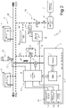
Figure 2 is a block diagram of a safety auxiliary system associated with the modular battery ofFigure 1 ; and -
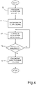
Figures 3 and4 show schematic flow diagrams of operations carried out by a first and by a second subsystems of the safety auxiliary system ofFigure 2 . - As will be made clear hereinafter, one aspect of the present solution envisages providing a modular battery, in particular a rechargeable Lithium battery, with a safety auxiliary system that operates in addition to the (known) safety mechanisms already incorporated in the "BMS" of the battery itself and that has the specific task of blocking the thermal runaway of one or more cells, or at least of minimising the consequences of the same thermal runaway, preventing the propagation thereof to surrounding cells.
- As schematically illustrated in
Figure 1 , the present solution has advantageous, even if not exclusive, application in an underwater vehicle 1 (for example a submarine), provided, for the purposes of the propulsion and/or for supplying electricity to corresponding on-board electrical systems, with abattery 2, in particular a modular rechargeable Lithium battery. - The
aforementioned battery 2 comprises a suitable number ofmodules 3, each containing a plurality ofcells 4, and a battery management system ("BMS") 6, of a known type, not described here in detail, comprising a control unit designed for managing the operation of themodule 3, in particular corresponding charging and discharging operations. - The
modules 3, in which thebattery 2 is divided, may for example be the same as one another, so that eachmodule 3 has a limited energy content; everymodule 3 is also enclosed in a corresponding hermetic container 3', capable of supporting a desired pressure difference between inside and outside, for example of the order of 1-2 Bar. - As indicated earlier, one aspect of the present solution envisages providing the
battery 2 with a safetyauxiliary system 10, which operates in addition to, and in cooperation with, the "BMS" 6 of themodules 3 of thebattery 2 and, in certain conditions, automatically activates to generate a strong and quick cooling of thecells 4 contained in asingle module 3 with the purpose of blocking the thermal runaway or in any case preventing the propagation thereof. - In particular, the safety
auxiliary system 10 is configured to activate, even repeatedly, whenever at least one of the following events is detected inside any one of themodules 3 of the battery 2: - temperature (of one or more cells 4) exceeding a predetermined threshold;
- temperature (of one or more cells 4) increasing with a higher rate than a respective predetermined threshold;
- overpressure in the container 3' of the module 3 (consequent to the "venting" of one or more cells 4);
- presence of smoke inside the container 3' of the module 3 (again, as a consequence of the "venting" of one or more cells 4).
- With reference to the block diagram of
Figure 2 , the aforementioned safetyauxiliary system 10 will now be described in greater detail, the system being in general divided into twosubsystems - a
first subsystem 10a, configured to detect conditions indicative of a thermal runaway in any one of themodules 3 and to manage such thermal runaway, intervening locally and exclusively on such amodule 3, immediately cooling thecorresponding cells 4 so that the thermal runaway is not propagated; - a
second subsystem 10b, cooperating with, and operatively coupled to, the aforementionedfirst subsystem 10a, configured to manage the gases that originate in the module 3 (due, at least in part, to thermal runaway), preventing them from pouring out into the closed environment inside theunderwater vehicle 1. - In greater detail, the
first subsystem 10a comprises, for eachmodule 3 of thebattery 2 the following elements (which, only for reasons of simplicity of illustration, are depicted only in association with an i-th module of thebattery 2 and not also for theother modules 3 of the battery, only the i-1th and i+1th modules of which are illustrated as examples inFigure 2 ): - an inlet electrovalve 12, normally closed and electronically controlled to allow entry into the
module 3 of a gas with high refrigerating and extinguishing effect (for example CO2 or other suitable gas, such as one of the Halon substitutes); - an outlet electrovalve 14, normally closed and electronically controlled to allow gas (in particular the refrigerant gas introduced from the outside, but also the possible gas produced by the "venting" of one or more overheated cells 4) to escape from the
module 3, thereby avoiding the creation of dangerous overpressure inside themodule 3; - a group of
sensors 15 positioned inside themodule 3 and configured to generate detection signals associated with quantities indicative of a thermal runaway in progress, possibly before the phenomenon produces "venting" of one ormore cells 4 of themodule 3; and - a first
electronic control unit 16, for example comprising a microprocessor, a microcontroller, a FPGA or an analogous programmable logic unit, operatively coupled to the group ofsensors 15, to acquire the detection signals, and moreover to the inlet andventing electrovalves venting electrovalves - The aforementioned first
electronic control unit 16 is shown schematically outside of the container 3' of thecorresponding module 3, but it is clear that it can also be housed inside the same container 3', in which case, with suitable protection from possible fires. - In greater detail, the group of
sensors 15 may comprise one or more of the following: - one or
more temperature sensors 15a, located in themodule 3 in the proximity of the cells 4 (it should be noted that a maximum responsiveness, and thus the maximum safety level, can be obtained with asingle temperature sensor 15a percell 4, configured to detect the temperature of thesingle cell 4 concerned); - a
pressure sensor 15b, configured to detect the pressure value inside themodule 3 and therefore the existence of overpressures inside thesame module 3 due to the "venting" of one ormore cells 4; - a
smoke sensor 15c, configured to detect the presence of smoke emitted by acell 4 in the "venting" phase. - It should be noted that, advantageously, the group of
sensors 15 may comprise all of the sensors listed earlier, to maximise the efficiency in the detection of the conditions indicative of the existence of a thermal runaway of one ormore cells 4 of themodule 3. - In the embodiment illustrated in the aforementioned
Figure 2 , thefirst subsystem 10a also comprises asafety valve 17, connected in parallel to the outlet electrovalve 14, configured to define, in the case of overpressure inside the module 3 (i.e. a pressure between inside and outside of the corresponding container 3' greater than a given predetermined threshold), a venting path for gas to escape from themodule 3 towards an outlet manifold (as described hereinafter), bypassing thesame outlet electrovalve 14. Such asafety valve 17 thus allows to avoid damage or breaking of the container 3' of themodule 3, in the case for example of incorrect readings by the group of sensors 15 (or damage to the same sensors) or failed introduction of the refrigerant gas (for example through a failure or exhaustion of the same refrigerant gas) . - In greater detail, the inlet electrovalve 12 of each module 3 (which is shown schematically in a position outside of the
module 3, but that may be physically located in the proximity of the container 3' of the same module 3) is coupled, by means of a common manifold 20 (which is in common between at least some of themodules 3 of the battery 2), to at least onecontainer 22 of refrigerant/extinguishing gas. - In particular, the
container 22 is provided with a respective electrovalve 23 (illustrated schematically inFigure 2 ) and with a corresponding control unit (not shown for the sake of simplicity inFigure 2 ), so that the delivery of gas takes place only upon electronic command, in the case of need; this allows to keep the pipes at atmospheric pressure except at the moment of actual use. By cooperating with the control unit of thecontainer 22, the firstelectronic control unit 16 of everysingle module 3 is capable of activating thecontainer 22 independently from theother modules 3, so as to determine the delivery of the refrigerant gas selectively and exclusively inside the corresponding container 3'. - The outlet electrovalve 14 of each module 3 (which is also shown schematically in a position outside the
module 3, but that may be physically located at the container 3' of the same module 3) is connected to anoutlet manifold 24, common to all of themodules 3 and connected to thesecond subsystem 10b of thesafety auxiliary system 10, having the function of managing the accumulation and the expulsion of the gases. - In detail, such
second subsystem 10b comprises (as illustrated schematically in the aforementionedFigure 2 ) the following elements, which are common for all of the modules 3: - an
accumulation tank 30, coupled to theoutlet manifold 24 and having the purpose of ensuring at any moment the possibility of accumulating gas, limiting the growth of pressure in the pipes; - a gas expulsion unit (so-called "box") 31 (which, in a known way, may be managed by the on-board systems of the
underwater vehicle 1, indicated schematically with 32), which allows the gases accumulated in theoutlet manifold 24 and in theaccumulation tank 30 to be discharged into the sea; - a
respective pressure sensor 33, configured to detect the pressure in theoutlet manifold 24, for example at theaccumulation tank 30; - a
discharge electrovalve 34, normally closed and electronically controlled to fluidically connect theaccumulation tank 30 to thegas expulsion unit 31, through anon-return valve 35; and - a second
electronic control unit 36, for example comprising a microprocessor, a microcontroller, an FPGA or an analogous programmable logic unit, operatively coupled to thepressure sensor 33 and also to the discharge electrovalve 34 to control, according to the pressure value detected by thepressure sensor 33, the same discharge electrovalve 34 (as described hereinafter) and therefore place theaccumulation tank 30 and thegas expulsion unit 31 in fluid connection. - In particular, the second
electronic control unit 36 of thesecond subsystem 10b and the firstelectronic control unit 16 of thefirst subsystem 10a are operatively coupled through a communication connection 38 (of the wired or wireless type). - The mechanism that allows the expulsion into the sea of the gases from the
gas expulsion unit 31 may be managed, in a per se known manner (not described here in detail) by on-board systems 32 of theunderwater vehicle 1, in a totally analogous way to what is implemented for the expansion tank or other tanks of saidunderwater vehicle 1 that are emptied and/or filled with seawater. - For example, the mechanism uses a pump that in a first step takes water from the sea and pours it (at higher pressure than hydrostatic pressure) into the
gas expulsion unit 31, thereby producing the expulsion of the corresponding content; thereafter, the same pump is used in reverse, taking water from thegas expulsion unit 31 and pouring it into the sea, thereby obtaining the emptying of the box. - Operation of the
safety auxiliary system 10 is now described in greater detail, firstly referring to the flow diagram ofFigure 3 and to the operations carried out by thefirst subsystem 10a, aimed at detecting and at managing the thermal runaway of one ormore cells 4 of any of themodules 3. - In a rest condition (i.e. with normal operation of the battery 2),
step 40, the firstelectronic control unit 16 of eachmodule 3 acquires, at a first sampling frequency "fc" (for example with sampling period of the order of a second), the detection signals detected by the associated group of sensors 15 (including thetemperature sensors 15a, thepressure sensor 15b and thesmoke sensor 15c); the samefirst control unit 16 also monitors the interface with the "BMS" 6 of themodule 3. - As soon as a thermal runaway in progress is detected,
step 41, the firstelectronic control unit 16, shifts into an alarm state, which is immediately signalled to the secondelectronic control unit 36 of thesecond subsystem 10b, through a suitable alarm signal Sal sent through thecommunication connection 38 between the first and secondelectronic control unit - As indicated earlier, the thermal runaway can be detected when one or more of the following conditions occur: temperature of one or
more cells 4 that exceeds a predetermined threshold; temperature of one ormore cells 4 that increases at a greater rate than a respective predetermined threshold; overpressure in the container 3' of themodule 3; presence of smoke inside the container 3'. - The signalling of the alarm state may be carried out, by the first
electronic control unit 16, also to the "BMS" 6 of the corresponding module 3 (for example by the immediate interruption of an optional charging/discharging step in progress), and moreover to a control system of the underwater vehicle 1 (for example, to the so-called "Combat System" in the case of a submersible, to quickly inform the crew of the dangerous situation). - During the alarm state,
step 42, all of the sensors of the group of sensors 5 are sampled at high speed, at a second sampling frequency, higher than the first sampling frequency, so as to be able to accurately detect and monitor the progress of the relevant quantities (in particular, temperature and pressure) inside themodule 3. - In alarm conditions the following sequence of actions is also carried out (and optionally repeated):
- the first
electronic control unit 16 controls,step 43, the opening of the electrovalve 23 arranged on thecontainer 22 of refrigerant gas and, immediately after, controls the opening of the inlet electrovalve 12 of thecorresponding module 3, to allow the introduction of the refrigerant gas inside the container 3' (further details on the control logic of theinlet electrovalve 12 will be provided hereinafter); in these conditions, the refrigerant gas flows from thecontainer 22 into thesole module 3 where the thermal runaway has occurred; - at the end of the delivery phase,
step 44, once a predetermined pressure value has been reached inside the container 3', or once a certain predetermined time period has elapsed, the firstelectronic control unit 16 closes both of the electrovalves (theelectrovalve 23 of thecontainer 22 and the inlet electrovalve 12 of the module 3) thereby stopping the flow of refrigerant gas to thesame module 3. - From this moment, the
overheated cell 4 and theother cells 4 give up heat to the refrigerant gas, which thus heats up and, not being able to expand, increases in pressure; at the same time, the temperature of theoverheated cell 4 drops sharply. - When the pressure inside the
module 3 exceeds a predetermined threshold, or the temperature of theoverheated cell 4 stops falling or stops falling at a desired rate (because the cooling effect has run out or is running out), the firstelectronic unit 16 controls the opening of theoutlet valve 14 for a predetermined time,step 45, thereby causing the refrigerant/extinguishing gas (together with the optional gas emitted by thecell 4 in thermal runaway) to come out from themodule 3 towards theaccumulation tank 30, initially empty (or, more precisely, containing air at atmospheric pressure). - It should be noted that, advantageously, the described process for dispensing refrigerant gas can be repeated once a certain time has elapsed, if the
cell 4 again shows great increases in temperature or "venting", as indicated instep 46. - Indeed, it should be noted that, in the case of use of containers 3' with relatively small free volume, the mass of refrigerant gas that may be transferred inside the
module 3 without reaching high pressures, is necessarily limited and, consequently, the cooling effect is also limited. It may therefore be required to replace the refrigerant gas in the container 3' many times, as a consequence of the fact that the refrigerant gas heats up and loses cooling capability. - Again for the purpose of limiting the risk of sharp rises in pressure inside the
module 3, it is also suitable for the introduction of the refrigerant gas to occur gradually (i.e. with a flow rate control thereof). - Such flow rate control may be obtained, for example, using a proportional electrovalve with electric flow rate adjustment.
- In order to reduce the cost of the system, at the same time ensuring efficiency, one aspect of the present solution on the other hand provides for the use of a common "On/Off" electrovalve for the
inlet electrovalve 12, which is controlled by the firstelectronic control unit 16 in pulsed mode, i.e. with a sequence of time-spaced pulses, instead of in a temporally continuous manner. - In particular, the first
electronic control unit 16, sampling the pressure in themodule 3 at high speed, establishes the width of the control pulses of the inlet electrovalve 12 (i.e. roughly adjusts the average flow rate of the refrigerant gas in a certain time period) so as to ensure that the pressure inside themodule 3 quickly reaches the predetermined value, at the same time minimising the risk of overpressures. - The predetermined pressure value is selected sufficiently high as to ensure the required cooling effect and, at the same time, sufficiently below the activation pressure of the
safety valve 17, so as not to cause the activation thereof. - It should be noted that the first
electronic control unit 16 in this way implements an automatic control in which the set-point is represented by the gas pressure that it is desired to obtain inside themodule 3, the control input is represented by the introduction flow rate of the refrigerant gas (adjusted by changing the width of the control pulses of the inlet electrovalve 12), and the "disturbance" (random, uncontrollable phenomenon) is represented by the heat produced by thecell 4 and by the possible "venting" thereof. - As shown in
Figure 4 , the secondelectronic control unit 36 of thesecond subsystem 10b (subsystem intended for controlling the accumulation and the expulsion of the gases), constantly controls the pressure in the venting system,step 50, through the acquisition of the signal detected by thepressure sensor 33, associated to theoutlet manifold 24 and to theaccumulation tank 30. - In normal operating conditions of the
battery 2, the monitoring of the pressure takes place at a first sampling frequency, for example at time intervals of a second; in alarm conditions (i.e. upon receiving,step 51, the alarm signal Sal sent by the firstelectronic control unit 16 through the dedicated communication line 38) the measurements are on the other hand carried out at high speed, at a second sampling frequency, higher than the first sampling frequency,step 52. - When the instantaneous reading of the
pressure sensor 33 exceeds a predetermined threshold,step 54, the secondelectronic control unit 36 controls the opening, for example for a predetermined time, of thedischarge electrovalve 34,step 55, so as to allow gas to flow in thegas expulsion unit 31. - From the same
gas expulsion unit 31, the gases will then be expelled into the sea, so as not to in any way contaminate the internal environment of theunderwater vehicle 1. - As indicated earlier, the opening of the discharge electrovalve 34 places the
accumulation tank 30 in communication with thegas expulsion unit 31. It should be noted that this does not cause the emptying, but only a reduction in pressure in theaccumulation tank 30, the percentage of which is greater as the volume of thegas expulsion unit 31 with respect to the volume of the other components (pipes and accumulation tank itself) is greater. - It is also noted that, for the entire duration of the expulsion operation of the gases (dependent on the solution adopted) the
gas expulsion unit 31 cannot be used, therefore all of the gas coming out from themodule 3 stays confined only in the pipes and in theaccumulation tank 30. - The advantages of the present solution emerge clearly from the above description.
- In any case, it should be emphasised that the proposed solution allows to substantially increase the safety of modular rechargeable Lithium batteries, in particular in the case of batteries of large size used in a submersible or more generally in an underwater vehicle.
- Advantageously, the refrigerant and extinguishing gas is dispensed only inside the
module 3 in which a thermal runaway has occurred, thanks to the presence in the same module of the group ofsensors 15 capable of detecting with certainty the presence of a thermal runaway in the initial step (progressive increase in temperature with anomalous rate of increase) or in the subsequent irreversible step (breaking of thecell 4, "venting", increase in pressure inside the module, presence of smoke). - Advantageously, for every
single module 3, the corresponding firstelectronic control unit 16 acquires the detection signals from the sensors of the group ofsensors 15 and controls the inlet and ventingelectrovalves module 3. - Moreover, adjustment of the introduction flow rate of the refrigerant gas into the
module 3 allows to minimise the risk of overpressures, controlling theinlet valve 12 with a sequence of pulses of variable width (which is determined in a suitable manner by the control logic). - The
outlet manifold 24, connected to theaccumulation tank 30, allows to avoid contaminating the internal air of theunderwater vehicle 1 with the refrigerant gas (for example CO2) and the "venting" gases produced by thecells 4. - The
same accumulation tank 30 may advantageously be emptied (at least partially) automatically, through the "gas expulsion box" managed by the on-board systems 32 of theunderwater vehicle 1, which allows the expulsion into the sea of the gases contained in it. - The communication of the alarm signal Sal by the
first control unit 16 of thefirst subsystem 10a to thesecond control unit 36 of thesecond subsystem 10b of thesafety auxiliary system 10 allows to accurately monitor the pressure in theaforementioned accumulation tank 30 and to immediately cause the emptying thereof, thereby ensuring the possibility of disposing of the gas that escapes from themodule 3 without the same gas contaminating the internal environment of theunderwater vehicle 1. - Finally, it is clear that modifications and variants can be brought to what has been described and illustrated here without for this reason departing from the scope of protection of the present invention, as defined in the attached claims.
- In particular, in the case of
large batteries 2, the supply pipes of the refrigerant gas could be of excessive length, compromising or in any case reducing the cooling efficiency of the same gas. In this hypothesis, themodules 3 may be grouped in a certain number N of groups and, instead of asingle container 22, it may be possible to useN containers 22 of reduced capacity (each of which is used for a single group) physically positioned close to themodules 3 that make up the corresponding group. - It should also be noted that the
accumulation tank 30 may be generally sized for a volume indicatively equal to the maximum volume of gas emitted by asingle cell 4 in the case of "venting"; for example, forcells 4 having a mass of 1 Kg, it is possible to provide a volume of the order of 200 litres. - In the hypothesis that the
safety auxiliary system 10 manages to prevent the propagation of the "venting" to thenearby cells 4, all of the gas emitted by thebattery 2 may optionally stay contained in the system and in theaccumulation tank 30 even without using the mechanism for expulsion into the sea. - Moreover, a further aspect of the present solution may provide that the first
electronic control unit 16, in the case of sudden interruption of the connections between the same firstelectronic control unit 16 and the group ofsensors 15 or sudden change in the data provided by them, due to damage to the sensors (since there is the possibility that the fire of themodule 3 might destroy or damage the group of sensors 15), prudently assumes that there is an "alarm and fire in progress" condition and therefore activates the inlet electrovalve 12 to put out the same fire. It should be noted that, in this particular case, the firstelectronic control unit 16 has no way of knowing whether the intervention has produced positive results, given that it will no longer be possible to use the signals coming from the sensors as "feedback". In this case, thefirst inlet electrovalve 12 will therefore be activated for a predetermined time and the same will happen for theoutlet electrovalve 14. - Finally, it should again be highlighted that the present solution is advantageously applicable to increase the safety of a
battery 2 preferably for use in a marine environment, for example inside a generic underwater vehicle, which may also differ from the submarine that has been specifically referred to earlier.
Claims (15)
- A safety auxiliary system (10), operatively coupled to a modular battery (2) having a number of modules (3), each provided with a plurality of cells (4), said system (10) comprising:a first subsystem (10a), configured to detect conditions indicative of a thermal runaway in any one of the modules (3) and to manage said thermal runaway, intervening locally on said module (3) to cool the corresponding cells (4) so that the thermal runaway is not propagated;
anda second subsystem (10b), cooperating with, and operatively coupled to, the first subsystem (10a), configured to manage gas present in the module (3) associated with the thermal runaway, preventing leaking thereof in an environment where said battery (2) is located,wherein said first subsystem (10a) comprises a first electronic control unit (16) for each of said modules (3),characterized in that said second subsystem (10b) comprises a second electronic control unit (36) distinct from, and operatively coupled to, said first electronic control unit (16) through a communication connection (38), so as to receive an alarm signal (Sal) upon detection of said conditions indicative of the thermal runaway in the corresponding module (3). - The system according to claim 1, wherein each of said modules (3) is provided with a corresponding hermetic container (3') which encloses the corresponding cells (4), and wherein said first subsystem (10a) comprises, for each of said modules (3):an inlet electrovalve (12) coupled, by means of a common manifold (20), in common with said modules (3), to at least one container (22) of refrigerant gas, electronically controlled by said first electronic control unit (16) to allow inlet of said refrigerant gas into the corresponding module (3) following the detection of said conditions indicative of a thermal runaway;an outlet electrovalve (14), electronically controlled by said first electronic control unit (16) to allow outflow of gas from the module (3) towards an outlet manifold (24);
anda group of sensors (15) positioned inside the module (3) and coupled with said first electronic control unit (16) to provide detection signals associated with quantities indicative of said thermal runaway;and wherein said second subsystem (10b) comprises:said outlet manifold (24), common to said modules (3) and connected to said modules (3) through the corresponding outlet electrovalve (14);a gas accumulation tank (30), coupled to the outlet manifold (24); anda discharge electrovalve (34), electronically controlled by said second electronic control unit (36) to fluidically connect said gas accumulation tank (30) to a gas expulsion unit (31). - The system according to claim 2, wherein said first electronic control unit (16) is configured to control said inlet electrovalve (12) to control the flow rate of the refrigerant gas introduced into said module (3) from said container (22), thereby avoiding overpressures inside the module (3).
- The system according to claim 3, wherein said first electronic control unit (16) is configured to control said inlet electrovalve (12) in pulsed mode, with a sequence of time-spaced control pulses, wherein the width of the control pulses is adjusted as a function of the pressure inside the module (3) and of a target pressure value to be reached, to ensure that the pressure inside the module (3) reaches the target pressure value, avoiding overpressures.
- The system according to any one of claims 2 to 4, wherein said group of sensors (15) comprises at least one of:one or more temperature sensors (15a), located in the module (3) in the proximity of the cells (4);a pressure sensor (15b), configured to detect the pressure inside the module (3); anda smoke sensor (15c), configured to detect the presence of smoke emitted by a cell (4) due to the thermal runaway.
- The system according to claim 5, wherein said first electronic control unit (16) is configured to sample the signals detected by the sensors of said group of sensors (15) at a first sampling frequency in a normal operating condition, and at a second sampling frequency, higher than said first sampling frequency, following the detection of said conditions indicative of a thermal runaway.
- The system according to any one of claims 2 to 6, wherein said first subsystem (10a) further comprises a safety valve (17) connected in parallel to the outlet electrovalve (14), configured to define, in the event of overpressure inside the module (3), a venting path for the outflow of gas from the module (3) towards said outlet manifold (24).
- The system according to any one of claims 2 to 7, wherein said container (22) is provided with a respective electrovalve (23) and a corresponding control unit cooperating with the first electronic control unit (16) of each module (3) to allow the delivery of gas from the container (22) into the corresponding module (3), independently of the other modules (3).
- The system according to any one of claims 2 to 8, wherein said second subsystem (10b) comprises a pressure sensor (33), configured to detect the pressure in the outlet manifold (24) and/or in said gas accumulation tank (30); wherein said second electronic control unit (36) is operatively coupled to said pressure sensor (33) and to the discharge electrovalve (34) to control, according to the pressure value detected by the pressure sensor (33), said discharge electrovalve (34) to fluidically connect said gas accumulation tank (30) to said gas expulsion unit (31) in order to expel the gas outside of the environment where said battery (2) is located.
- The system according to claim 9, wherein said second electronic control unit (36) is configured to sample the signal detected by said pressure sensor (33) at a first sampling frequency in a normal operating condition, and at a second sampling frequency, higher than said first sampling frequency, following reception of said alarm signal (Sal) from said first electronic control unit (16).
- The system according to claim 9 or 10, wherein said battery (2) is located in an underwater vehicle (1) and wherein said gas expulsion unit (31) is an expulsion module for discharging into the sea the gas accumulated in the outlet manifold (24) and in the accumulation tank (30).
- The system according to any one of the preceding claims, wherein said battery (2) is a rechargeable Lithium battery.
- A battery (2) having a number of modules (3), each provided with a plurality of cells (4), comprising a safety auxiliary system (10) according to any one of the preceding claims.
- The battery according to claim 13, of the rechargeable Lithium type.
- An underwater vehicle (1) comprising the battery according to claim 13 or 14 and the safety auxiliary system (10) according to any one of claims 1-12.
Applications Claiming Priority (1)
| Application Number | Priority Date | Filing Date | Title |
|---|---|---|---|
| IT102019000001735A IT201900001735A1 (en) | 2019-02-06 | 2019-02-06 | AUXILIARY SAFETY SYSTEM FOR A MODULAR BATTERY IN AN UNDERWATER VEHICLE AND ITS BATTERY |
Publications (2)
| Publication Number | Publication Date |
|---|---|
| EP3694045A1 EP3694045A1 (en) | 2020-08-12 |
| EP3694045B1 true EP3694045B1 (en) | 2022-05-25 |
Family
ID=69701226
Family Applications (1)
| Application Number | Title | Priority Date | Filing Date |
|---|---|---|---|
| EP20155971.3A Active EP3694045B1 (en) | 2019-02-06 | 2020-02-06 | Safety auxiliary system for a modular battery in an underwater vehicle and corresponding battery |
Country Status (3)
| Country | Link |
|---|---|
| US (1) | US11476537B2 (en) |
| EP (1) | EP3694045B1 (en) |
| IT (1) | IT201900001735A1 (en) |
Families Citing this family (7)
| Publication number | Priority date | Publication date | Assignee | Title |
|---|---|---|---|---|
| KR102738646B1 (en) * | 2019-07-23 | 2024-12-06 | 주식회사 엘지에너지솔루션 | Apparatus For Fire Detection of Vehicle Battery and Method Thereof |
| GB2599697A (en) * | 2020-10-09 | 2022-04-13 | Ea Rs Fire Eng Ltd | Energy storage system monitoring and protection system |
| CN112731169B (en) * | 2020-12-22 | 2022-08-23 | 上汽大众汽车有限公司 | All-weather monitoring system and method for thermal runaway of power battery |
| CN114883738B (en) * | 2022-04-24 | 2023-05-09 | 中国船舶科学研究中心 | Protection device and control method for battery compartment of deep-sea submersible |
| JP2026504508A (en) * | 2023-04-14 | 2026-02-05 | 寧徳時代新能源科技股▲分▼有限公司 | Battery and its thermal runaway early warning method, device and storage medium |
| KR102945940B1 (en) * | 2023-07-31 | 2026-03-30 | 재단법인 중소조선연구원 | battery fire suppression system of electric propulsion ship |
| EP4611150A1 (en) * | 2024-02-28 | 2025-09-03 | Samsung SDI Co., Ltd. | Battery system with improved venting mechanism |
Family Cites Families (4)
| Publication number | Priority date | Publication date | Assignee | Title |
|---|---|---|---|---|
| US7433794B1 (en) * | 2007-07-18 | 2008-10-07 | Tesla Motors, Inc. | Mitigation of propagation of thermal runaway in a multi-cell battery pack |
| US9704384B2 (en) * | 2012-05-22 | 2017-07-11 | Lawrence Livermore National Security, Llc | Battery management systems with thermally integrated fire suppression |
| KR101942908B1 (en) * | 2015-09-14 | 2019-04-17 | 주식회사 엘지화학 | System and method for detecting battery swelling |
| CN107623147A (en) * | 2017-09-26 | 2018-01-23 | 深圳市曼晶创业投资咨询企业(有限合伙) | The self-extinguishing of power cells for new energy vehicles bag and the device and its application method of emergent cooling |
-
2019
- 2019-02-06 IT IT102019000001735A patent/IT201900001735A1/en unknown
-
2020
- 2020-02-05 US US16/782,270 patent/US11476537B2/en active Active
- 2020-02-06 EP EP20155971.3A patent/EP3694045B1/en active Active
Also Published As
| Publication number | Publication date |
|---|---|
| EP3694045A1 (en) | 2020-08-12 |
| US11476537B2 (en) | 2022-10-18 |
| IT201900001735A1 (en) | 2020-08-06 |
| US20200251706A1 (en) | 2020-08-06 |
Similar Documents
| Publication | Publication Date | Title |
|---|---|---|
| US11476537B2 (en) | Safety auxiliary system for a modular battery in an underwater vehicle and corresponding battery | |
| CN114051668B (en) | Fire suppression device | |
| JP6961671B2 (en) | Rechargeable battery fire prevention system | |
| CN110711326B (en) | Fire extinguishing system for high voltage battery of motor vehicle and motor vehicle with fire extinguishing system | |
| EP3709386A1 (en) | Battery pack storage device and control method therefor | |
| CN111790083A (en) | A lithium-ion battery thermal runaway early warning fire extinguishing system and method | |
| US20220328893A1 (en) | Marine battery safety system and method | |
| CN114552055A (en) | Method and cooling system for cooling and extinguishing a hot battery module of a high-voltage battery of a motor vehicle | |
| CN112972938A (en) | Motor vehicle having a supply connection for a fire extinguishing agent outside the vehicle | |
| KR102406230B1 (en) | Control method of cooling and fire extinguishing system of ESS with enhanced safety | |
| KR20210075235A (en) | Fire detection sensor module for lithium ion battery and system including the same | |
| FI12774Y1 (en) | Storage container for batteries | |
| EP3798040A1 (en) | Battery pack for an electric vehicle provided with a safety system for thermal runaway | |
| CN118477271A (en) | Fire engine power lithium battery thermal runaway early warning system and control method | |
| KR20230044831A (en) | Fire Extinguishing System for Energy Storage System | |
| EP3742517B1 (en) | Method for delivering fire suppressing agent to lithium ion battery module | |
| CN115212494B (en) | Fire fighting system and energy storage equipment for energy storage equipment | |
| JP2010158286A (en) | Sprinkler fire extinguishing equipment | |
| ES2980285B2 (en) | Battery charging and storage control system | |
| CN217548836U (en) | Fire extinguishing system | |
| KR20240095389A (en) | Battery fire suppression system | |
| US20230211198A1 (en) | Inerting intermittent suppression system | |
| CN212466891U (en) | Energy storage device | |
| CN114470570B (en) | Fire extinguishing system | |
| GB2599697A (en) | Energy storage system monitoring and protection system |
Legal Events
| Date | Code | Title | Description |
|---|---|---|---|
| PUAI | Public reference made under article 153(3) epc to a published international application that has entered the european phase |
Free format text: ORIGINAL CODE: 0009012 |
|
| STAA | Information on the status of an ep patent application or granted ep patent |
Free format text: STATUS: THE APPLICATION HAS BEEN PUBLISHED |
|
| AK | Designated contracting states |
Kind code of ref document: A1 Designated state(s): AL AT BE BG CH CY CZ DE DK EE ES FI FR GB GR HR HU IE IS IT LI LT LU LV MC MK MT NL NO PL PT RO RS SE SI SK SM TR |
|
| AX | Request for extension of the european patent |
Extension state: BA ME |
|
| STAA | Information on the status of an ep patent application or granted ep patent |
Free format text: STATUS: REQUEST FOR EXAMINATION WAS MADE |
|
| 17P | Request for examination filed |
Effective date: 20210125 |
|
| RBV | Designated contracting states (corrected) |
Designated state(s): AL AT BE BG CH CY CZ DE DK EE ES FI FR GB GR HR HU IE IS IT LI LT LU LV MC MK MT NL NO PL PT RO RS SE SI SK SM TR |
|
| GRAP | Despatch of communication of intention to grant a patent |
Free format text: ORIGINAL CODE: EPIDOSNIGR1 |
|
| STAA | Information on the status of an ep patent application or granted ep patent |
Free format text: STATUS: GRANT OF PATENT IS INTENDED |
|
| INTG | Intention to grant announced |
Effective date: 20211206 |
|
| GRAS | Grant fee paid |
Free format text: ORIGINAL CODE: EPIDOSNIGR3 |
|
| GRAA | (expected) grant |
Free format text: ORIGINAL CODE: 0009210 |
|
| STAA | Information on the status of an ep patent application or granted ep patent |
Free format text: STATUS: THE PATENT HAS BEEN GRANTED |
|
| AK | Designated contracting states |
Kind code of ref document: B1 Designated state(s): AL AT BE BG CH CY CZ DE DK EE ES FI FR GB GR HR HU IE IS IT LI LT LU LV MC MK MT NL NO PL PT RO RS SE SI SK SM TR |
|
| RAP3 | Party data changed (applicant data changed or rights of an application transferred) |
Owner name: LEONARDO S.P.A. |
|
| REG | Reference to a national code |
Ref country code: GB Ref legal event code: FG4D |
|
| REG | Reference to a national code |
Ref country code: CH Ref legal event code: EP |
|
| REG | Reference to a national code |
Ref country code: DE Ref legal event code: R096 Ref document number: 602020003261 Country of ref document: DE |
|
| REG | Reference to a national code |
Ref country code: AT Ref legal event code: REF Ref document number: 1494622 Country of ref document: AT Kind code of ref document: T Effective date: 20220615 |
|
| REG | Reference to a national code |
Ref country code: IE Ref legal event code: FG4D |
|
| REG | Reference to a national code |
Ref country code: LT Ref legal event code: MG9D |
|
| REG | Reference to a national code |
Ref country code: NL Ref legal event code: MP Effective date: 20220525 |
|
| REG | Reference to a national code |
Ref country code: AT Ref legal event code: MK05 Ref document number: 1494622 Country of ref document: AT Kind code of ref document: T Effective date: 20220525 |
|
| PG25 | Lapsed in a contracting state [announced via postgrant information from national office to epo] |
Ref country code: SE Free format text: LAPSE BECAUSE OF FAILURE TO SUBMIT A TRANSLATION OF THE DESCRIPTION OR TO PAY THE FEE WITHIN THE PRESCRIBED TIME-LIMIT Effective date: 20220525 Ref country code: PT Free format text: LAPSE BECAUSE OF FAILURE TO SUBMIT A TRANSLATION OF THE DESCRIPTION OR TO PAY THE FEE WITHIN THE PRESCRIBED TIME-LIMIT Effective date: 20220926 Ref country code: NO Free format text: LAPSE BECAUSE OF FAILURE TO SUBMIT A TRANSLATION OF THE DESCRIPTION OR TO PAY THE FEE WITHIN THE PRESCRIBED TIME-LIMIT Effective date: 20220825 Ref country code: NL Free format text: LAPSE BECAUSE OF FAILURE TO SUBMIT A TRANSLATION OF THE DESCRIPTION OR TO PAY THE FEE WITHIN THE PRESCRIBED TIME-LIMIT Effective date: 20220525 Ref country code: LT Free format text: LAPSE BECAUSE OF FAILURE TO SUBMIT A TRANSLATION OF THE DESCRIPTION OR TO PAY THE FEE WITHIN THE PRESCRIBED TIME-LIMIT Effective date: 20220525 Ref country code: HR Free format text: LAPSE BECAUSE OF FAILURE TO SUBMIT A TRANSLATION OF THE DESCRIPTION OR TO PAY THE FEE WITHIN THE PRESCRIBED TIME-LIMIT Effective date: 20220525 Ref country code: GR Free format text: LAPSE BECAUSE OF FAILURE TO SUBMIT A TRANSLATION OF THE DESCRIPTION OR TO PAY THE FEE WITHIN THE PRESCRIBED TIME-LIMIT Effective date: 20220826 Ref country code: FI Free format text: LAPSE BECAUSE OF FAILURE TO SUBMIT A TRANSLATION OF THE DESCRIPTION OR TO PAY THE FEE WITHIN THE PRESCRIBED TIME-LIMIT Effective date: 20220525 Ref country code: ES Free format text: LAPSE BECAUSE OF FAILURE TO SUBMIT A TRANSLATION OF THE DESCRIPTION OR TO PAY THE FEE WITHIN THE PRESCRIBED TIME-LIMIT Effective date: 20220525 Ref country code: BG Free format text: LAPSE BECAUSE OF FAILURE TO SUBMIT A TRANSLATION OF THE DESCRIPTION OR TO PAY THE FEE WITHIN THE PRESCRIBED TIME-LIMIT Effective date: 20220825 Ref country code: AT Free format text: LAPSE BECAUSE OF FAILURE TO SUBMIT A TRANSLATION OF THE DESCRIPTION OR TO PAY THE FEE WITHIN THE PRESCRIBED TIME-LIMIT Effective date: 20220525 |
|
| PG25 | Lapsed in a contracting state [announced via postgrant information from national office to epo] |
Ref country code: RS Free format text: LAPSE BECAUSE OF FAILURE TO SUBMIT A TRANSLATION OF THE DESCRIPTION OR TO PAY THE FEE WITHIN THE PRESCRIBED TIME-LIMIT Effective date: 20220525 Ref country code: PL Free format text: LAPSE BECAUSE OF FAILURE TO SUBMIT A TRANSLATION OF THE DESCRIPTION OR TO PAY THE FEE WITHIN THE PRESCRIBED TIME-LIMIT Effective date: 20220525 Ref country code: LV Free format text: LAPSE BECAUSE OF FAILURE TO SUBMIT A TRANSLATION OF THE DESCRIPTION OR TO PAY THE FEE WITHIN THE PRESCRIBED TIME-LIMIT Effective date: 20220525 Ref country code: IS Free format text: LAPSE BECAUSE OF FAILURE TO SUBMIT A TRANSLATION OF THE DESCRIPTION OR TO PAY THE FEE WITHIN THE PRESCRIBED TIME-LIMIT Effective date: 20220925 |
|
| PG25 | Lapsed in a contracting state [announced via postgrant information from national office to epo] |
Ref country code: SM Free format text: LAPSE BECAUSE OF FAILURE TO SUBMIT A TRANSLATION OF THE DESCRIPTION OR TO PAY THE FEE WITHIN THE PRESCRIBED TIME-LIMIT Effective date: 20220525 Ref country code: SK Free format text: LAPSE BECAUSE OF FAILURE TO SUBMIT A TRANSLATION OF THE DESCRIPTION OR TO PAY THE FEE WITHIN THE PRESCRIBED TIME-LIMIT Effective date: 20220525 Ref country code: RO Free format text: LAPSE BECAUSE OF FAILURE TO SUBMIT A TRANSLATION OF THE DESCRIPTION OR TO PAY THE FEE WITHIN THE PRESCRIBED TIME-LIMIT Effective date: 20220525 Ref country code: EE Free format text: LAPSE BECAUSE OF FAILURE TO SUBMIT A TRANSLATION OF THE DESCRIPTION OR TO PAY THE FEE WITHIN THE PRESCRIBED TIME-LIMIT Effective date: 20220525 Ref country code: DK Free format text: LAPSE BECAUSE OF FAILURE TO SUBMIT A TRANSLATION OF THE DESCRIPTION OR TO PAY THE FEE WITHIN THE PRESCRIBED TIME-LIMIT Effective date: 20220525 Ref country code: CZ Free format text: LAPSE BECAUSE OF FAILURE TO SUBMIT A TRANSLATION OF THE DESCRIPTION OR TO PAY THE FEE WITHIN THE PRESCRIBED TIME-LIMIT Effective date: 20220525 |
|
| REG | Reference to a national code |
Ref country code: DE Ref legal event code: R097 Ref document number: 602020003261 Country of ref document: DE |
|
| PG25 | Lapsed in a contracting state [announced via postgrant information from national office to epo] |
Ref country code: AL Free format text: LAPSE BECAUSE OF FAILURE TO SUBMIT A TRANSLATION OF THE DESCRIPTION OR TO PAY THE FEE WITHIN THE PRESCRIBED TIME-LIMIT Effective date: 20220525 |
|
| PLBE | No opposition filed within time limit |
Free format text: ORIGINAL CODE: 0009261 |
|
| STAA | Information on the status of an ep patent application or granted ep patent |
Free format text: STATUS: NO OPPOSITION FILED WITHIN TIME LIMIT |
|
| 26N | No opposition filed |
Effective date: 20230228 |
|
| PG25 | Lapsed in a contracting state [announced via postgrant information from national office to epo] |
Ref country code: SI Free format text: LAPSE BECAUSE OF FAILURE TO SUBMIT A TRANSLATION OF THE DESCRIPTION OR TO PAY THE FEE WITHIN THE PRESCRIBED TIME-LIMIT Effective date: 20220525 |
|
| PG25 | Lapsed in a contracting state [announced via postgrant information from national office to epo] |
Ref country code: MC Free format text: LAPSE BECAUSE OF FAILURE TO SUBMIT A TRANSLATION OF THE DESCRIPTION OR TO PAY THE FEE WITHIN THE PRESCRIBED TIME-LIMIT Effective date: 20220525 |
|
| REG | Reference to a national code |
Ref country code: CH Ref legal event code: PL |
|
| REG | Reference to a national code |
Ref country code: BE Ref legal event code: MM Effective date: 20230228 |
|
| PG25 | Lapsed in a contracting state [announced via postgrant information from national office to epo] |
Ref country code: LU Free format text: LAPSE BECAUSE OF NON-PAYMENT OF DUE FEES Effective date: 20230206 Ref country code: LI Free format text: LAPSE BECAUSE OF NON-PAYMENT OF DUE FEES Effective date: 20230228 Ref country code: CH Free format text: LAPSE BECAUSE OF NON-PAYMENT OF DUE FEES Effective date: 20230228 |
|
| REG | Reference to a national code |
Ref country code: IE Ref legal event code: MM4A |
|
| PG25 | Lapsed in a contracting state [announced via postgrant information from national office to epo] |
Ref country code: IT Free format text: LAPSE BECAUSE OF FAILURE TO SUBMIT A TRANSLATION OF THE DESCRIPTION OR TO PAY THE FEE WITHIN THE PRESCRIBED TIME-LIMIT Effective date: 20220525 Ref country code: IE Free format text: LAPSE BECAUSE OF NON-PAYMENT OF DUE FEES Effective date: 20230206 |
|
| PG25 | Lapsed in a contracting state [announced via postgrant information from national office to epo] |
Ref country code: BE Free format text: LAPSE BECAUSE OF NON-PAYMENT OF DUE FEES Effective date: 20230228 |
|
| PG25 | Lapsed in a contracting state [announced via postgrant information from national office to epo] |
Ref country code: BG Free format text: LAPSE BECAUSE OF FAILURE TO SUBMIT A TRANSLATION OF THE DESCRIPTION OR TO PAY THE FEE WITHIN THE PRESCRIBED TIME-LIMIT Effective date: 20220525 |
|
| PG25 | Lapsed in a contracting state [announced via postgrant information from national office to epo] |
Ref country code: BG Free format text: LAPSE BECAUSE OF FAILURE TO SUBMIT A TRANSLATION OF THE DESCRIPTION OR TO PAY THE FEE WITHIN THE PRESCRIBED TIME-LIMIT Effective date: 20220525 |
|
| REG | Reference to a national code |
Ref country code: DE Ref legal event code: R081 Ref document number: 602020003261 Country of ref document: DE Owner name: WASS SUBMARINE SYSTEMS S.R.L., IT Free format text: FORMER OWNER: LEONARDO S.P.A., ROMA, IT |
|
| REG | Reference to a national code |
Ref country code: GB Ref legal event code: 732E Free format text: REGISTERED BETWEEN 20250424 AND 20250430 |
|
| PG25 | Lapsed in a contracting state [announced via postgrant information from national office to epo] |
Ref country code: CY Free format text: LAPSE BECAUSE OF FAILURE TO SUBMIT A TRANSLATION OF THE DESCRIPTION OR TO PAY THE FEE WITHIN THE PRESCRIBED TIME-LIMIT; INVALID AB INITIO Effective date: 20200206 |
|
| PG25 | Lapsed in a contracting state [announced via postgrant information from national office to epo] |
Ref country code: HU Free format text: LAPSE BECAUSE OF FAILURE TO SUBMIT A TRANSLATION OF THE DESCRIPTION OR TO PAY THE FEE WITHIN THE PRESCRIBED TIME-LIMIT; INVALID AB INITIO Effective date: 20200206 |
|
| PG25 | Lapsed in a contracting state [announced via postgrant information from national office to epo] |
Ref country code: TR Free format text: LAPSE BECAUSE OF FAILURE TO SUBMIT A TRANSLATION OF THE DESCRIPTION OR TO PAY THE FEE WITHIN THE PRESCRIBED TIME-LIMIT Effective date: 20220525 |
|
| PGFP | Annual fee paid to national office [announced via postgrant information from national office to epo] |
Ref country code: GB Payment date: 20260223 Year of fee payment: 7 |
|
| PGFP | Annual fee paid to national office [announced via postgrant information from national office to epo] |
Ref country code: DE Payment date: 20260220 Year of fee payment: 7 |
|
| PGFP | Annual fee paid to national office [announced via postgrant information from national office to epo] |
Ref country code: FR Payment date: 20260227 Year of fee payment: 7 |