EP3693988A1 - Relay contactor dual linear actuator module system - Google Patents
Relay contactor dual linear actuator module system Download PDFInfo
- Publication number
- EP3693988A1 EP3693988A1 EP19209702.0A EP19209702A EP3693988A1 EP 3693988 A1 EP3693988 A1 EP 3693988A1 EP 19209702 A EP19209702 A EP 19209702A EP 3693988 A1 EP3693988 A1 EP 3693988A1
- Authority
- EP
- European Patent Office
- Prior art keywords
- shaft
- plate
- actuator
- input
- output leads
- Prior art date
- Legal status (The legal status is an assumption and is not a legal conclusion. Google has not performed a legal analysis and makes no representation as to the accuracy of the status listed.)
- Granted
Links
Images


Classifications
-
- H—ELECTRICITY
- H01—ELECTRIC ELEMENTS
- H01H—ELECTRIC SWITCHES; RELAYS; SELECTORS; EMERGENCY PROTECTIVE DEVICES
- H01H51/00—Electromagnetic relays
- H01H51/02—Non-polarised relays
- H01H51/04—Non-polarised relays with single armature; with single set of ganged armatures
- H01H51/12—Armature is movable between two limit positions of rest and is moved in both directions due to the energisation of one or the other of two electromagnets without the storage of energy to effect the return movement
-
- H—ELECTRICITY
- H01—ELECTRIC ELEMENTS
- H01H—ELECTRIC SWITCHES; RELAYS; SELECTORS; EMERGENCY PROTECTIVE DEVICES
- H01H50/00—Details of electromagnetic relays
- H01H50/64—Driving arrangements between movable part of magnetic circuit and contact
- H01H50/641—Driving arrangements between movable part of magnetic circuit and contact intermediate part performing a rectilinear movement
-
- H—ELECTRICITY
- H01—ELECTRIC ELEMENTS
- H01F—MAGNETS; INDUCTANCES; TRANSFORMERS; SELECTION OF MATERIALS FOR THEIR MAGNETIC PROPERTIES
- H01F7/00—Magnets
- H01F7/06—Electromagnets; Actuators including electromagnets
- H01F7/08—Electromagnets; Actuators including electromagnets with armatures
- H01F7/16—Rectilinearly-movable armatures
- H01F7/1607—Armatures entering the winding
-
- H—ELECTRICITY
- H01—ELECTRIC ELEMENTS
- H01H—ELECTRIC SWITCHES; RELAYS; SELECTORS; EMERGENCY PROTECTIVE DEVICES
- H01H50/00—Details of electromagnetic relays
- H01H50/16—Magnetic circuit arrangements
- H01H50/18—Movable parts of magnetic circuits, e.g. armature
- H01H50/20—Movable parts of magnetic circuits, e.g. armature movable inside coil and substantially lengthwise with respect to axis thereof; movable coaxially with respect to coil
-
- H—ELECTRICITY
- H01—ELECTRIC ELEMENTS
- H01H—ELECTRIC SWITCHES; RELAYS; SELECTORS; EMERGENCY PROTECTIVE DEVICES
- H01H50/00—Details of electromagnetic relays
- H01H50/44—Magnetic coils or windings
-
- H—ELECTRICITY
- H01—ELECTRIC ELEMENTS
- H01H—ELECTRIC SWITCHES; RELAYS; SELECTORS; EMERGENCY PROTECTIVE DEVICES
- H01H50/00—Details of electromagnetic relays
- H01H50/54—Contact arrangements
-
- H—ELECTRICITY
- H01—ELECTRIC ELEMENTS
- H01H—ELECTRIC SWITCHES; RELAYS; SELECTORS; EMERGENCY PROTECTIVE DEVICES
- H01H50/00—Details of electromagnetic relays
- H01H50/54—Contact arrangements
- H01H50/546—Contact arrangements for contactors having bridging contacts
-
- H—ELECTRICITY
- H01—ELECTRIC ELEMENTS
- H01H—ELECTRIC SWITCHES; RELAYS; SELECTORS; EMERGENCY PROTECTIVE DEVICES
- H01H51/00—Electromagnetic relays
- H01H51/02—Non-polarised relays
- H01H51/20—Non-polarised relays with two or more independent armatures
-
- H—ELECTRICITY
- H01—ELECTRIC ELEMENTS
- H01F—MAGNETS; INDUCTANCES; TRANSFORMERS; SELECTION OF MATERIALS FOR THEIR MAGNETIC PROPERTIES
- H01F7/00—Magnets
- H01F7/06—Electromagnets; Actuators including electromagnets
- H01F7/08—Electromagnets; Actuators including electromagnets with armatures
- H01F7/16—Rectilinearly-movable armatures
- H01F7/1607—Armatures entering the winding
- H01F2007/163—Armatures entering the winding with axial bearing
Definitions
- the following description relates to relay contactors and, more particularly, to a relay contactor with a dual linear actuator module system.
- the present standard for high amperage relays or contactors is to have a single linear motor actuator with an armature mechanically connected to movable electrical contacts by way of a shaft assembly.
- the armature and the shaft assembly are supported only on the side of the motor and the movable electrical contacts are provided on a free, unsupported end of the shaft assembly.
- the single linear motor actuator includes a stator with a coil winding or windings.
- the armature passes through the single linear motor actuator structure on bushings and with linkages, including springs and other similar features, on the end of the shaft assembly, which is provided as a cantilever structure, and which is connected to the movable electrical contacts.
- the electrical connections have to significantly increase in size in order to handle the amperage power flow.
- the electrical movable contact masses i.e., combined mechanical and electrical elements are increased.
- a relay contactor includes input and output leads, a shaft assembly, an actuator and first and second bearing assemblies.
- the shaft assembly includes a shaft, a plate disposed on the shaft and an elastic element. The shaft and the plate are movable between an open position at which the plate is displaced from the input and output leads and a closed position at which the plate contacts the input and output leads.
- the actuator is coupled to the shaft at a first side of the plate and is configured to selectively move the shaft and the plate into the closed position in opposition to bias applied by the elastic element.
- the first and second bearing assemblies are disposed to movably support the shaft at the first side and at a second side of the plate, respectively.
- a housing houses the input and output leads, the shaft assembly, the actuator and the first and second bearing assemblies.
- the input and output leads include first and second conductive elements, respectively, and the plate includes third and fourth conductive elements that are disposed to contact the first and second conductive elements, respectively, when the shaft and the plate are moved into the closed position.
- the shaft extends through a space defined between the input and output leads, the actuator and the first bearing assembly are disposed on a first side of the input and output leads and the plate and the second bearing assembly are disposed on a second side of the input and output leads.
- the elastic element is anchored at opposite ends thereof to the actuator and the shaft or the plate.
- the actuator includes a linear actuator.
- the actuator includes an armature through which the shaft extends, coils surrounding the armature and an actuator housing supportive of the first bearing assembly and configured to house the armature and the coils.
- a relay contactor includes input and output leads, a shaft assembly, first and second actuators and first and second bearing assemblies.
- the shaft assembly includes a shaft, a plate disposed on the shaft and an elastic element. The shaft and the plate are movable between an open position at which the plate is displaced from the input and output leads and a closed position at which the plate contacts the input and output leads.
- the first and second actuators are coupled to the shaft at first and second sides of the plate, respectively, and are configured to selectively move the shaft and the plate into the closed position in opposition to bias applied by the elastic element.
- the first and second bearing assemblies are disposed to movably support the shaft at the first and second sides of the plate, respectively.
- a housing houses the input and output leads, the shaft assembly, the first and second actuators and the first and second bearing assemblies.
- the input and output leads include first and second conductive elements, respectively, and the plate includes third and fourth conductive elements that are disposed to contact the first and second conductive elements, respectively, when the shaft and the plate are moved into the closed position.
- first, second, third and fourth conductive elements are disposed at an angle.
- the first, second, third and fourth conductive elements are hemispherical.
- the shaft extends through a space defined between the input and output leads, the first actuator and the first bearing assembly are disposed on a first side of the input and output leads and the plate, the second actuator and the second bearing assembly are disposed on a second side of the input and output leads.
- the elastic element includes a first elastic element anchored at opposite ends thereof to the first actuator and the shaft and a second elastic element anchored at opposite ends thereof to the second actuator and the shaft or the plate.
- the first and second actuators are independently or dependently operable.
- the first and second actuators each include a linear actuator.
- the first actuator includes a first armature through which the shaft extends, first coils surrounding the first armature and a first actuator housing supportive of the first bearing assembly and configured to house the first armature and the first coils and the second actuator includes a second armature through which the shaft extends, second coils surrounding the second armature and a second actuator housing supportive of the second bearing assembly and configured to house the second armature and the second coils.
- a relay contactor includes first and second pairs of input and output leads, a shaft assembly, first and second actuators and first and second bearing assemblies.
- the shaft assembly includes a shaft, a plate disposed on the shaft and an elastic element. The shaft and the plate are movable between first and second positions at which the plate is positioned at first and second positions with respect to the first and second pairs of the input and output leads, respectively.
- the first and second actuators are coupled to the shaft at first and second sides of the plate, respectively, and are configured to selectively move the shaft and the plate between the first and second positions in opposition to bias applied by the elastic element.
- the first and second bearing assemblies are disposed to movably support the shaft at the first and second sides of the plate, respectively.
- the first position is characterized in that the plate is displaced from the first pair of the input and output leads and in contact with the second pair of the input and output leads and the second position is characterized in that the plate is displaced from the second pair of the input and output leads and in contact with the first pair of the input and output leads.
- the first position is characterized in that the plate is displaced from the first and second pairs of the input and output leads and the second position is characterized in that the plate is in contact with the first and second pairs of the input and output leads.
- a linear actuator motor While a single linear actuator motor is now provided as an industry standard, it is characterized as having movable electrical contacts at a free, unsupported end of a shaft with high masses to handle the high power requirements of aerospace applications. This leads to the armature and the shaft being difficult to move during high-speed switching and to the armature and shaft having a tendency to vibrate.
- a linear motor design is provided in which the armature is supported on both ends of the shaft.
- a contactor or a large relay actuator system is provided with moveable electrical contacts between two or dual separate linear motor coil actuator assemblies, so that the actuator armature and shaft system is mechanically supported on both ends.
- This dual motor actuator configuration can allow the armature, springs, insulators and sliding bearings to be configured to optimize the movable structure for large electrical conductors (high amperage) in high vibration environments.
- an aircraft power distribution system 10 includes a primary power distribution box 12 that receives power from a generator 14 through power leads 28.
- the primary power distribution box 12 provides power through supply leads 46 to a secondary power distribution box 16, which distributes power to first and second loads 18 and 20, for example.
- the primary power distribution box 12 includes a board 24 that is arranged within a housing 22.
- the board 24 supports plug-in pins 26 that are connected to the power leads 28.
- Mechanical contactors 30 act as switches to selectively electrically connect the power leads 28 to the supply leads 46.
- Circuit breakers 48 are supported by the board 24 to selectively disconnect the supply leads 46 from power in response to an overload.
- the board 24 also supports a connector 32 that communicates with a control 34 through a harness 36.
- the control 34 provides commands to the board 24 and/or a secondary circuit board 38 and receives feedback regarding various functions related to the aircraft power distribution system 10.
- the secondary circuit board 38 is mounted on the board 24 and is connected to the connector 32 and contactors 30 through connections 39.
- the secondary circuit board 38 includes protection circuitry 40 and secondary power distribution circuitry 42.
- the protection circuitry 40 monitors the current provided by the generator 14, for example, to prevent the secondary power distribution box 16 from exposure to undesired currents.
- the secondary power distribution circuitry 42 commands the contact
- the contactors 30 are illustrated with control traces 50 and power traces 66 which are supported by the board 24 and connected to the secondary circuit board 38 and secondary power distribution connectors 44, respectively.
- the board 24 is relatively thick to accommodate the current flowing through the power traces 66.
- the contactors 30 are connected to the plug-in pins 26 by first bands 52 and second bands (not shown).
- the power traces 66 are selectively provided with power when a plate 60 is moved into a closed position connecting first and second contacts.
- the plate 60 is moved between open and closed positions by a linear motor and shaft assembly to be described below.
- the linear motor and shaft assembly is mounted to the board 24 and is commanded by the secondary power distribution circuitry 42 through the control traces 50.
- the current flowing through the power traces 66 is monitored by the protection circuitry 42 through the control traces 50.
- a relay contactor 301 is provided for use in or as the contactors 30 of FIGS. 1 and 2 .
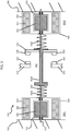
- the relay contactor 301 includes an input lead 310 that is configured to carry current supplied from the power leads 28 of FIG. 2 , an output lead 320 that is configured to carry current to the power traces 66 of FIG. 2 , a shaft assembly 330, first and second actuators 340 and 350 and first and second bearing assemblies 360 and 370.
- the relay contactor 301 may further include a housing 380, which is configured to house respectively portions of the input lead 310 and the output lead 320, the shaft assembly 330, the first and second actuators 340 and 350 and the first and second bearing assemblies 360 and 370.
- the input lead 310 includes an electrically conductive body that extends to an exterior of the housing 380 and a first electrical contact 311 at a proximal end of the electrically conductive body within the housing 380.
- the output lead 320 includes an electrically conductive body that extends to an exterior of the housing 380 and a second electrical contact 321 at a proximal end of the electrically conductive body within the housing 380.
- the shaft assembly 330 includes a shaft 331 that can span the housing 380, a plate 332 that is disposed on the shaft 331, shaft isolation sleeve 3320 that is interposed between the shaft 331 and the plate 332 and an elastic element 333.
- the plate 332 includes an electrically conductive body and third and fourth electrical contacts 334 and 335 at opposite ends of the electrically conductive body.
- the shaft 331 and the plate 332 are movable together along a longitudinal axis of the shaft 331 between an open position and a closed position.
- the third and fourth electrical contacts 334 and 335 of the plate 332 are displaced from electrical contact with the first electrical contact 311 of the input lead 310 and from electrical contact with second electrical contact 321 of the output lead 320, respectively, such that the input lead 310 and the output lead 320 are not electrically communicative with one another (i.e., current from the power leads 28 is not transmitted to the power traces 66).
- the third and fourth electrical contacts 334 and 335 of the plate 332 are disposed in electrical contact with the first electrical contact 311 of the input lead 310 and in electrical contact with second electrical contact 321 of the output lead 320, respectively, such that the input lead 310 and the output lead 320 are electrically communicative (i.e., current from the power leads 28 is transmitted to the power traces 66).
- the shaft isolation sleeve 3320 serves to electrically insulate or isolate the plate 332 from the shaft 331.
- the elastic element 333 can be disposed to apply a bias to the shaft 331 and the plate 332 which urges the shaft 331 and the plate 332 toward assumption of the open position.
- first and second electrical contacts 311 and 321 and the third and fourth electrical contacts 334 and 335 can be hemispherical or otherwise curved, flat-faced or otherwise configured to form reliable electrical contacts.
- the first actuator 340 is coupled to the shaft 331 at a first side 3321 of the plate 332.
- the second actuator 350 is coupled to the shaft 331 at a second side 3322 of the plate 332.
- the first and second actuators 340 and 350 are configured to be independently or dependently operable so as to selectively move the shaft 331 and the plate 332 into the closed position in opposition to bias applied by the elastic element 333.
- the first actuator 340 may include or be provided as a linear actuator.
- the first actuator 340 may include a first armature 341 through which the shaft 331 extends, first coils 342 surrounding the first armature 341 and a first actuator housing 343 that is supportive of the first bearing assembly 360 and configured to house the first armature 341 and the first coils 342.
- the second actuator 350 may include or be provided as a linear actuator.
- the second actuator 350 may include a second armature 351 through which the shaft 331 extends, second coils 352 surrounding the second armature 351 and a second actuator housing 353 that is supportive of the second bearing assembly 370 and configured to house the second armature 351 and the second coils 352.
- Electrical insulation (isolation) of the plate 332 from the shaft assembly 330 can be achieved, for example, by material selection of the shaft isolation sleeve 3320.
- the first bearing assembly 360 is disposed to movably support the shaft 331 at the first side 3321 of the plate 332 and the second bearing assembly 370 is disposed to movably support the 331 shaft at the second side 3322 of the plate 332.
- the first bearing assembly 360 can include bearing elements that are secured in the first actuator housing 343 to permit movements of the shaft 331 along the longitudinal axis of the shaft 331 and the second bearing assembly can include bearing elements that are secured in the second actuator housing 353 to permit the movement of the shaft along the longitudinal axis of the shaft 331.
- the proximal ends of the electrically conductive bodies of the input and output leads 310 and 320 define or form a space or opening through which the shaft 331 extends, the first actuator 340 and the first bearing assembly 360 are disposed on a first side of the input and output leads 310 and 320 and the plate 332, the second actuator 350 and the second bearing assembly 370 are disposed on a second side of the input and output leads 310 and 320.
- the first actuator 340 and the first bearing assembly 360 are disposed on a first side of the input and output leads 310 and 320 and the plate 332
- the second actuator 350 and the second bearing assembly 370 are disposed on a second side of the input and output leads 310 and 320.
- the elastic element 333 can include a first elastic element 3331, which is anchored at opposite ends thereof to the first actuator 340 and the shaft 331, and a second elastic element 3332, which is anchored at opposite ends thereof to the second actuator 350 and the shaft 331 or the plate 332.
- the first and second coils 342 and 352 of the first and second actuators 340 and 350 can be independently or dependently energized to thus generate magnetic flux which brings the shaft 331 and the plate 332 into the closed position in opposition to the bias applied by the elastic element 333.
- the first and second coils 342 and 352 can be disposed in parallel or in series within an energization circuit and the elastic element 333 can be optimized for use with the various components of the first and second actuators 340 and 350.
- FIG. 3 has been illustrated with first and second actuators 340 and 350, it is to be understood that this is not required.
- the second actuator 350 is not included in the relay contactor 301.
- the second bearing assembly 370 could include bearing elements that are secured to the housing 380 at the second side 3322 of the plate 332 and the second elastic element 3332 could be anchored at the opposite ends thereof to the housing 380 and the shaft 331 or the plate 332.
- the elastic elements 3331 and 3332 can be electrically isolated from the plate 332 by the shaft isolation sleeve 3320.
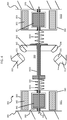
- the relay contactor 301 is illustrated in accordance with alternative embodiments in which the first and second electrical contacts 311 and 321 and the third and fourth electrical contacts 334 and 335 are disposed at an angle with respect to the longitudinal axis of the shaft 331.
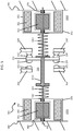
- the relay contactor 301 is illustrated in accordance with alternative embodiments in which the input and output leads 310 and 320 are provided as first and second pairs of input and output leads 310 and 320 and 310' and 320' and the shaft 331 and the plate 332 are movable between first and second positions at which the plate 332 is positioned at first and second positions with respect to the first and second pairs of the input and output leads 310 and 320 and 310' and 320'. As shown in FIG.
- the first position is characterized in that the plate 332, which has additional third and fourth electrical contacts 334' and 335', is displaced from the first pair of the input and output leads 310 and 320 and in electrical contact with the second pair of the input and output leads 310' and 320' and the second position is characterized in that the plate 332 is displaced from the second pair of the input and output leads 310' and 320' and in electrical contact with the first pair of the input and output leads 310 and 320 (i.e., one of the first and second pairs of input and output leads 310 and 320 is normally open and the other of the first and second pairs of input and output leads 310' and 320' is normally closed). As shown in FIG.
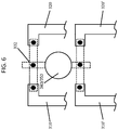
- the first position is characterized in that the plate 332 is displaced from the first and second pairs of the input and output leads 310 and 320 and 310' and 320' and the second position is characterized in that the plate 332 is in electrical contact with the first and second pairs of the input and output leads 310 and 320 and 310' and 320' (i.e., both the first and second pairs of input and output leads 310 and 320 and 310' and 320' are either normally open or closed).
Landscapes
- Physics & Mathematics (AREA)
- Electromagnetism (AREA)
- Engineering & Computer Science (AREA)
- Power Engineering (AREA)
- Connection Of Motors, Electrical Generators, Mechanical Devices, And The Like (AREA)
Abstract
Description
- The following description relates to relay contactors and, more particularly, to a relay contactor with a dual linear actuator module system.
- The present standard for high amperage relays or contactors is to have a single linear motor actuator with an armature mechanically connected to movable electrical contacts by way of a shaft assembly. The armature and the shaft assembly are supported only on the side of the motor and the movable electrical contacts are provided on a free, unsupported end of the shaft assembly.
- The single linear motor actuator includes a stator with a coil winding or windings. The armature passes through the single linear motor actuator structure on bushings and with linkages, including springs and other similar features, on the end of the shaft assembly, which is provided as a cantilever structure, and which is connected to the movable electrical contacts.
- As amperage increases in power levels to 1000's of amperes at steady state (the present aerospace production component high amperage is around 450A), the electrical connections have to significantly increase in size in order to handle the amperage power flow. As such, the electrical movable contact masses (i.e., combined mechanical and electrical elements are increased. With the high mass electrical movable contacts provided on the free end of a shaft assembly, the armature, the shaft assembly and the electrical movable contacts become mechanically difficult to hold in vibratory modes and to move to achieve high speed switching.
- According to an aspect of the disclosure, a relay contactor is provided and includes input and output leads, a shaft assembly, an actuator and first and second bearing assemblies. The shaft assembly includes a shaft, a plate disposed on the shaft and an elastic element. The shaft and the plate are movable between an open position at which the plate is displaced from the input and output leads and a closed position at which the plate contacts the input and output leads. The actuator is coupled to the shaft at a first side of the plate and is configured to selectively move the shaft and the plate into the closed position in opposition to bias applied by the elastic element. The first and second bearing assemblies are disposed to movably support the shaft at the first side and at a second side of the plate, respectively.
- In accordance with additional or alternative embodiments, a housing houses the input and output leads, the shaft assembly, the actuator and the first and second bearing assemblies.
- In accordance with additional or alternative embodiments, the input and output leads include first and second conductive elements, respectively, and the plate includes third and fourth conductive elements that are disposed to contact the first and second conductive elements, respectively, when the shaft and the plate are moved into the closed position.
- In accordance with additional or alternative embodiments, the shaft extends through a space defined between the input and output leads, the actuator and the first bearing assembly are disposed on a first side of the input and output leads and the plate and the second bearing assembly are disposed on a second side of the input and output leads.
- In accordance with additional or alternative embodiments, the elastic element is anchored at opposite ends thereof to the actuator and the shaft or the plate.
- In accordance with additional or alternative embodiments, the actuator includes a linear actuator.
- In accordance with additional or alternative embodiments, the actuator includes an armature through which the shaft extends, coils surrounding the armature and an actuator housing supportive of the first bearing assembly and configured to house the armature and the coils.
- According to an aspect of the disclosure, a relay contactor is provided and includes input and output leads, a shaft assembly, first and second actuators and first and second bearing assemblies. The shaft assembly includes a shaft, a plate disposed on the shaft and an elastic element. The shaft and the plate are movable between an open position at which the plate is displaced from the input and output leads and a closed position at which the plate contacts the input and output leads. The first and second actuators are coupled to the shaft at first and second sides of the plate, respectively, and are configured to selectively move the shaft and the plate into the closed position in opposition to bias applied by the elastic element. The first and second bearing assemblies are disposed to movably support the shaft at the first and second sides of the plate, respectively.
- In accordance with additional or alternative embodiments, a housing houses the input and output leads, the shaft assembly, the first and second actuators and the first and second bearing assemblies.
- In accordance with additional or alternative embodiments, the input and output leads include first and second conductive elements, respectively, and the plate includes third and fourth conductive elements that are disposed to contact the first and second conductive elements, respectively, when the shaft and the plate are moved into the closed position.
- In accordance with additional or alternative embodiments, the first, second, third and fourth conductive elements are disposed at an angle.
- In accordance with additional or alternative embodiments, the first, second, third and fourth conductive elements are hemispherical.
- In accordance with additional or alternative embodiments, the shaft extends through a space defined between the input and output leads, the first actuator and the first bearing assembly are disposed on a first side of the input and output leads and the plate, the second actuator and the second bearing assembly are disposed on a second side of the input and output leads.
- In accordance with additional or alternative embodiments, the elastic element includes a first elastic element anchored at opposite ends thereof to the first actuator and the shaft and a second elastic element anchored at opposite ends thereof to the second actuator and the shaft or the plate.
- In accordance with additional or alternative embodiments, the first and second actuators are independently or dependently operable.
- In accordance with additional or alternative embodiments, the first and second actuators each include a linear actuator.
- In accordance with additional or alternative embodiments, the first actuator includes a first armature through which the shaft extends, first coils surrounding the first armature and a first actuator housing supportive of the first bearing assembly and configured to house the first armature and the first coils and the second actuator includes a second armature through which the shaft extends, second coils surrounding the second armature and a second actuator housing supportive of the second bearing assembly and configured to house the second armature and the second coils.
- According to another aspect of the disclosure, a relay contactor is provided and includes first and second pairs of input and output leads, a shaft assembly, first and second actuators and first and second bearing assemblies. The shaft assembly includes a shaft, a plate disposed on the shaft and an elastic element. The shaft and the plate are movable between first and second positions at which the plate is positioned at first and second positions with respect to the first and second pairs of the input and output leads, respectively. The first and second actuators are coupled to the shaft at first and second sides of the plate, respectively, and are configured to selectively move the shaft and the plate between the first and second positions in opposition to bias applied by the elastic element. The first and second bearing assemblies are disposed to movably support the shaft at the first and second sides of the plate, respectively.
- In accordance with additional or alternative embodiments, the first position is characterized in that the plate is displaced from the first pair of the input and output leads and in contact with the second pair of the input and output leads and the second position is characterized in that the plate is displaced from the second pair of the input and output leads and in contact with the first pair of the input and output leads.
- In accordance with additional or alternative embodiments, the first position is characterized in that the plate is displaced from the first and second pairs of the input and output leads and the second position is characterized in that the plate is in contact with the first and second pairs of the input and output leads.
- These and other advantages and features will become more apparent from the following description taken in conjunction with the drawings.
- The subject matter, which is regarded as the disclosure, is particularly pointed out and distinctly claimed in the claims at the conclusion of the specification. The foregoing and other features, and advantages of the disclosure are apparent from the following detailed description taken in conjunction with the accompanying drawings in which:
-
FIG. 1 is a schematic view of an aircraft power distribution system with a generator and a module with an integrated relay contactor; -
FIG. 2 is a top elevation view of a portion of a primary power distribution board shown inFIG. 1 with an integrated relay contactor; -
FIG. 3 is a side schematic illustration of a relay contactor for use with the aircraft distribution system ofFIG. 1 and the primary power distribution board ofFIG. 2 in accordance with embodiments; -
FIG. 4 is a side schematic illustration of a relay contactor for use with the aircraft distribution system ofFIG. 1 and the primary power distribution board ofFIG. 2 in accordance with alternative embodiments; -
FIG. 5 is a side schematic illustration of a relay contactor for use with the aircraft distribution system ofFIG. 1 and the primary power distribution board ofFIG. 2 in accordance with alternative embodiments; and -
FIG. 6 is an axial schematic illustration of a relay contactor for use with the aircraft distribution system ofFIG. 1 and the primary power distribution board ofFIG. 2 in accordance with alternative embodiments. - These and other advantages and features will become more apparent from the following description taken in conjunction with the drawings.
- While a single linear actuator motor is now provided as an industry standard, it is characterized as having movable electrical contacts at a free, unsupported end of a shaft with high masses to handle the high power requirements of aerospace applications. This leads to the armature and the shaft being difficult to move during high-speed switching and to the armature and shaft having a tendency to vibrate. Thus, as will be described below, a linear motor design is provided in which the armature is supported on both ends of the shaft. In an exemplary case, a contactor or a large relay actuator system is provided with moveable electrical contacts between two or dual separate linear motor coil actuator assemblies, so that the actuator armature and shaft system is mechanically supported on both ends. This dual motor actuator configuration can allow the armature, springs, insulators and sliding bearings to be configured to optimize the movable structure for large electrical conductors (high amperage) in high vibration environments.
- With reference to
FIGS. 1 and2 , an aircraftpower distribution system 10 includes a primary power distribution box 12 that receives power from a generator 14 through power leads 28. The primary power distribution box 12 provides power through supply leads 46 to a secondary power distribution box 16, which distributes power to first andsecond loads - The primary power distribution box 12 includes a
board 24 that is arranged within ahousing 22. Theboard 24 supports plug-inpins 26 that are connected to the power leads 28.Mechanical contactors 30 act as switches to selectively electrically connect the power leads 28 to the supply leads 46.Circuit breakers 48 are supported by theboard 24 to selectively disconnect the supply leads 46 from power in response to an overload. Theboard 24 also supports aconnector 32 that communicates with acontrol 34 through a harness 36. Thecontrol 34 provides commands to theboard 24 and/or asecondary circuit board 38 and receives feedback regarding various functions related to the aircraftpower distribution system 10. Thesecondary circuit board 38 is mounted on theboard 24 and is connected to theconnector 32 andcontactors 30 throughconnections 39. Thesecondary circuit board 38 includes protection circuitry 40 and secondary power distribution circuitry 42. The protection circuitry 40 monitors the current provided by the generator 14, for example, to prevent the secondary power distribution box 16 from exposure to undesired currents. The secondary power distribution circuitry 42 commands thecontactors 30 between open and closed positions. - The
contactors 30 are illustrated with control traces 50 and power traces 66 which are supported by theboard 24 and connected to thesecondary circuit board 38 and secondary power distribution connectors 44, respectively. Theboard 24 is relatively thick to accommodate the current flowing through the power traces 66. Thecontactors 30 are connected to the plug-inpins 26 byfirst bands 52 and second bands (not shown). The power traces 66 are selectively provided with power when a plate 60 is moved into a closed position connecting first and second contacts. The plate 60 is moved between open and closed positions by a linear motor and shaft assembly to be described below. The linear motor and shaft assembly is mounted to theboard 24 and is commanded by the secondary power distribution circuitry 42 through the control traces 50. The current flowing through the power traces 66 is monitored by the protection circuitry 42 through the control traces 50. - With reference to
FIG. 3 , arelay contactor 301 is provided for use in or as thecontactors 30 ofFIGS. 1 and2 . As shown inFIG. 3 , therelay contactor 301 includes aninput lead 310 that is configured to carry current supplied from the power leads 28 ofFIG. 2 , anoutput lead 320 that is configured to carry current to the power traces 66 ofFIG. 2 , ashaft assembly 330, first andsecond actuators second bearing assemblies relay contactor 301 may further include ahousing 380, which is configured to house respectively portions of theinput lead 310 and theoutput lead 320, theshaft assembly 330, the first andsecond actuators second bearing assemblies - The
input lead 310 includes an electrically conductive body that extends to an exterior of thehousing 380 and a firstelectrical contact 311 at a proximal end of the electrically conductive body within thehousing 380. Theoutput lead 320 includes an electrically conductive body that extends to an exterior of thehousing 380 and a secondelectrical contact 321 at a proximal end of the electrically conductive body within thehousing 380. - The
shaft assembly 330 includes ashaft 331 that can span thehousing 380, aplate 332 that is disposed on theshaft 331,shaft isolation sleeve 3320 that is interposed between theshaft 331 and theplate 332 and anelastic element 333. Theplate 332 includes an electrically conductive body and third and fourthelectrical contacts shaft 331 and theplate 332 are movable together along a longitudinal axis of theshaft 331 between an open position and a closed position. At the open position, the third and fourthelectrical contacts plate 332 are displaced from electrical contact with the firstelectrical contact 311 of theinput lead 310 and from electrical contact with secondelectrical contact 321 of theoutput lead 320, respectively, such that theinput lead 310 and theoutput lead 320 are not electrically communicative with one another (i.e., current from the power leads 28 is not transmitted to the power traces 66). At the closed position, the third and fourthelectrical contacts plate 332 are disposed in electrical contact with the firstelectrical contact 311 of theinput lead 310 and in electrical contact with secondelectrical contact 321 of theoutput lead 320, respectively, such that theinput lead 310 and theoutput lead 320 are electrically communicative (i.e., current from the power leads 28 is transmitted to the power traces 66). Theshaft isolation sleeve 3320 serves to electrically insulate or isolate theplate 332 from theshaft 331. Theelastic element 333 can be disposed to apply a bias to theshaft 331 and theplate 332 which urges theshaft 331 and theplate 332 toward assumption of the open position. - In accordance with embodiments, the first and second
electrical contacts electrical contacts - The
first actuator 340 is coupled to theshaft 331 at afirst side 3321 of theplate 332. Thesecond actuator 350 is coupled to theshaft 331 at asecond side 3322 of theplate 332. The first andsecond actuators shaft 331 and theplate 332 into the closed position in opposition to bias applied by theelastic element 333. - In accordance with embodiments, the
first actuator 340 may include or be provided as a linear actuator. In this or other cases, thefirst actuator 340 may include afirst armature 341 through which theshaft 331 extends,first coils 342 surrounding thefirst armature 341 and afirst actuator housing 343 that is supportive of thefirst bearing assembly 360 and configured to house thefirst armature 341 and thefirst coils 342. In accordance with similar embodiments, thesecond actuator 350 may include or be provided as a linear actuator. In this or other cases, thesecond actuator 350 may include asecond armature 351 through which theshaft 331 extends,second coils 352 surrounding thesecond armature 351 and asecond actuator housing 353 that is supportive of thesecond bearing assembly 370 and configured to house thesecond armature 351 and thesecond coils 352. - Electrical insulation (isolation) of the
plate 332 from theshaft assembly 330 can be achieved, for example, by material selection of theshaft isolation sleeve 3320. - With the first and
second actuators first bearing assembly 360 is disposed to movably support theshaft 331 at thefirst side 3321 of theplate 332 and thesecond bearing assembly 370 is disposed to movably support the 331 shaft at thesecond side 3322 of theplate 332. Thefirst bearing assembly 360 can include bearing elements that are secured in thefirst actuator housing 343 to permit movements of theshaft 331 along the longitudinal axis of theshaft 331 and the second bearing assembly can include bearing elements that are secured in thesecond actuator housing 353 to permit the movement of the shaft along the longitudinal axis of theshaft 331. - As shown in
FIG. 3 , the proximal ends of the electrically conductive bodies of the input and output leads 310 and 320 define or form a space or opening through which theshaft 331 extends, thefirst actuator 340 and thefirst bearing assembly 360 are disposed on a first side of the input and output leads 310 and 320 and theplate 332, thesecond actuator 350 and thesecond bearing assembly 370 are disposed on a second side of the input and output leads 310 and 320. In addition, as shown inFIG. 3 , theelastic element 333 can include a firstelastic element 3331, which is anchored at opposite ends thereof to thefirst actuator 340 and theshaft 331, and a secondelastic element 3332, which is anchored at opposite ends thereof to thesecond actuator 350 and theshaft 331 or theplate 332. - During an operation of the
relay contactor 301, the first andsecond coils second actuators shaft 331 and theplate 332 into the closed position in opposition to the bias applied by theelastic element 333. To this end, the first andsecond coils elastic element 333 can be optimized for use with the various components of the first andsecond actuators - Although
FIG. 3 has been illustrated with first andsecond actuators second actuator 350 is not included in therelay contactor 301. In these or other cases, thesecond bearing assembly 370 could include bearing elements that are secured to thehousing 380 at thesecond side 3322 of theplate 332 and the secondelastic element 3332 could be anchored at the opposite ends thereof to thehousing 380 and theshaft 331 or theplate 332. - The
elastic elements plate 332 by theshaft isolation sleeve 3320. - With reference to
FIG. 4 , therelay contactor 301 is illustrated in accordance with alternative embodiments in which the first and secondelectrical contacts electrical contacts shaft 331. - With reference to
FIGS. 5 and6 , therelay contactor 301 is illustrated in accordance with alternative embodiments in which the input and output leads 310 and 320 are provided as first and second pairs of input and output leads 310 and 320 and 310' and 320' and theshaft 331 and theplate 332 are movable between first and second positions at which theplate 332 is positioned at first and second positions with respect to the first and second pairs of the input and output leads 310 and 320 and 310' and 320'. As shown inFIG. 5 , the first position is characterized in that theplate 332, which has additional third and fourth electrical contacts 334' and 335', is displaced from the first pair of the input and output leads 310 and 320 and in electrical contact with the second pair of the input and output leads 310' and 320' and the second position is characterized in that theplate 332 is displaced from the second pair of the input and output leads 310' and 320' and in electrical contact with the first pair of the input and output leads 310 and 320 (i.e., one of the first and second pairs of input and output leads 310 and 320 is normally open and the other of the first and second pairs of input and output leads 310' and 320' is normally closed). As shown inFIG. 6 , the first position is characterized in that theplate 332 is displaced from the first and second pairs of the input and output leads 310 and 320 and 310' and 320' and the second position is characterized in that theplate 332 is in electrical contact with the first and second pairs of the input and output leads 310 and 320 and 310' and 320' (i.e., both the first and second pairs of input and output leads 310 and 320 and 310' and 320' are either normally open or closed). - Technical effects and benefits of the features described herein are the provision of a dual linear motor actuator with a compact size, capacity to handle heavy movable electrical contracts for small motor assemblies and a spring system optimized for an armature structure, electrical conductive material mass and dual coil (motor) power.
- While the disclosure is provided in detail in connection with only a limited number of embodiments, it should be readily understood that the disclosure is not limited to such disclosed embodiments. Rather, the disclosure can be modified to incorporate any number of variations, alterations, substitutions or equivalent arrangements not heretofore described, but which are commensurate with the spirit and scope of the disclosure. Additionally, while various embodiments of the disclosure have been described, it is to be understood that the exemplary embodiment(s) may include only some of the described exemplary aspects. Accordingly, the disclosure is not to be seen as limited by the foregoing description, but is only limited by the scope of the appended claims.
Claims (15)
- A relay contactor, comprising:input and output leads (310,320);a shaft assembly (330) comprising a shaft (331), a plate (332) disposed on the shaft and an elastic element (333), the shaft and the plate being movable between an open position at which the plate is displaced from the input and output leads and a closed position at which the plate contacts the input and output leads;an actuator (340) coupled to the shaft at a first side of the plate, the actuator being configured to selectively move the shaft and the plate into the closed position in opposition to bias applied by the elastic element; andfirst and second bearing assemblies (360,370) disposed to movably support the shaft at the first side and at a second side of the plate, respectively.
- The relay contactor according to claim 1, further comprising a housing (380) to house the input and output leads, the shaft assembly, the actuator and the first and second bearing assemblies.
- The relay contactor according to claim 1 or 2, wherein:the input and output leads comprise first and second conductive elements, respectively, andthe plate comprises third and fourth conductive elements that are disposed to contact the first and second conductive elements, respectively, when the shaft and the plate are moved into the closed position.
- The relay contactor according to claim 3, wherein the first, second, third and fourth conductive elements are disposed at an angle.
- The relay contactor according to claim 3 or 4, wherein the first, second, third and fourth conductive elements are hemispherical.
- The relay contactor according to any preceding claim, wherein,
the shaft extends through a space defined between the input and output leads,
the actuator and the first bearing assembly are disposed on a first side of the input and output leads, and
the plate and the second bearing assembly are disposed on a second side of the input and output leads. - The relay contactor according to any preceding claim, wherein the elastic element is anchored at opposite ends thereof to the actuator and the shaft or the plate.
- The relay contactor according to any preceding claim, wherein the actuator comprises a linear actuator, or wherein the actuator comprises:an armature (341) through which the shaft extends;coils (342) surrounding the armature; andan actuator housing (343) supportive of the first bearing assembly and configured to house the armature and the coils.
- The relay contactor of any preceding claim, wherein the actuator is a first actuator, and further comprising:
a second actuator (350) coupled to the shaft at the second side of the plate, and configured to selectively move the shaft and the plate into the closed position in opposition to bias applied by the elastic element. - The relay contactor according to claim 9, wherein,
the shaft extends through a space defined between the input and output leads,
the first actuator and the first bearing assembly are disposed on a first side of the input and output leads, and
the plate, the second actuator and the second bearing assembly are disposed on a second side of the input and output leads. - The relay contactor according to claim 9 or 10, wherein the elastic element comprises:a first elastic element anchored at opposite ends thereof to the first actuator and the shaft; anda second elastic element anchored at opposite ends thereof to the second actuator and the shaft or the plate.
- The relay contactor according to claim 9, 10 or 11, wherein the first and second actuators are independently or dependently operable.
- The relay contactor according to any of claims 9 to 12, wherein:the first actuator (340) comprises a first armature (341) through which the shaft extends, first coils (342) surrounding the first armature and a first actuator housing (343) supportive of the first bearing assembly and configured to house the first armature and the first coils, andthe second actuator (350) comprises a second armature (351) through which the shaft extends, second coils (352) surrounding the second armature and a second actuator housing (353) supportive of the second bearing assembly and configured to house the second armature and the second coils.
- The relay contactor of claim 9, wherein said input and output leads comprise:
first and second pairs of input and output leads. - The relay contactor according to claim 14, wherein:the first position is characterized in that the plate is displaced from the first pair of the input and output leads and in contact with the second pair of the input and output leads, andthe second position is characterized in that the plate is displaced from the second pair of the input and output leads and in contact with the first pair of the input and output leads; or wherein:the first position is characterized in that the plate is displaced from the first and second pairs of the input and output leads, andthe second position is characterized in that the plate is in contact with the first and second pairs of the input and output leads.
Applications Claiming Priority (1)
| Application Number | Priority Date | Filing Date | Title |
|---|---|---|---|
| US16/270,364 US11133141B2 (en) | 2019-02-07 | 2019-02-07 | Relay contactor dual linear actuator module system |
Publications (2)
| Publication Number | Publication Date |
|---|---|
| EP3693988A1 true EP3693988A1 (en) | 2020-08-12 |
| EP3693988B1 EP3693988B1 (en) | 2025-06-04 |
Family
ID=68609970
Family Applications (1)
| Application Number | Title | Priority Date | Filing Date |
|---|---|---|---|
| EP19209702.0A Active EP3693988B1 (en) | 2019-02-07 | 2019-11-18 | Relay contactor dual linear actuator module system |
Country Status (2)
| Country | Link |
|---|---|
| US (2) | US11133141B2 (en) |
| EP (1) | EP3693988B1 (en) |
Cited By (1)
| Publication number | Priority date | Publication date | Assignee | Title |
|---|---|---|---|---|
| CN115938862A (en) * | 2021-10-05 | 2023-04-07 | 通用汽车环球科技运作有限责任公司 | Arrangements and modules for electrical contactor assemblies |
Families Citing this family (2)
| Publication number | Priority date | Publication date | Assignee | Title |
|---|---|---|---|---|
| GB2579848A (en) * | 2018-12-18 | 2020-07-08 | Eaton Intelligent Power Ltd | Electromagnetic drive unit for a switching device and switching device |
| CN114429871B (en) * | 2020-10-29 | 2025-02-28 | 施耐德电器工业公司 | Moving contact pressure holding structure, moving contact assembly and dual power conversion switch |
Citations (5)
| Publication number | Priority date | Publication date | Assignee | Title |
|---|---|---|---|---|
| US1503717A (en) * | 1920-06-03 | 1924-08-05 | Westinghouse Electric & Mfg Co | Control apparatus and system |
| DE604819C (en) * | 1930-07-05 | 1934-10-29 | Siemens Schuckertwerke Akt Ges | Multi-pole toggle relay, especially for remote control systems |
| US2919324A (en) * | 1958-08-04 | 1959-12-29 | Leach Corp | Magnetic shuttle device |
| US3836879A (en) * | 1973-10-15 | 1974-09-17 | Norco Sales And Mfg Co | Dual reversing solenoid operated switch |
| EP3116014A1 (en) * | 2015-07-08 | 2017-01-11 | TE Connectivity Germany GmbH | Electrical switching arrangement with improved linear bearing |
Family Cites Families (5)
| Publication number | Priority date | Publication date | Assignee | Title |
|---|---|---|---|---|
| US2725488A (en) * | 1951-10-03 | 1955-11-29 | Leece Neville Co | Series-parallel switch and battery circuit |
| US4529953A (en) * | 1982-09-01 | 1985-07-16 | Electromation, Inc. | Electrical switch |
| US6958671B2 (en) * | 2001-11-15 | 2005-10-25 | Square D Company | Electrical contactor with positive temperature coefficient resistivity element |
| US7538990B2 (en) | 2006-12-14 | 2009-05-26 | Hamilton Sundstrand Corporation | High voltage DC contactor hybrid without a DC arc break |
| US8559149B2 (en) | 2008-05-05 | 2013-10-15 | Hamilton Sundstrand Corporation | Modular primary distribution contact board |
-
2019
- 2019-02-07 US US16/270,364 patent/US11133141B2/en active Active
- 2019-11-18 EP EP19209702.0A patent/EP3693988B1/en active Active
-
2021
- 2021-09-23 US US17/482,971 patent/US11657996B2/en active Active
Patent Citations (5)
| Publication number | Priority date | Publication date | Assignee | Title |
|---|---|---|---|---|
| US1503717A (en) * | 1920-06-03 | 1924-08-05 | Westinghouse Electric & Mfg Co | Control apparatus and system |
| DE604819C (en) * | 1930-07-05 | 1934-10-29 | Siemens Schuckertwerke Akt Ges | Multi-pole toggle relay, especially for remote control systems |
| US2919324A (en) * | 1958-08-04 | 1959-12-29 | Leach Corp | Magnetic shuttle device |
| US3836879A (en) * | 1973-10-15 | 1974-09-17 | Norco Sales And Mfg Co | Dual reversing solenoid operated switch |
| EP3116014A1 (en) * | 2015-07-08 | 2017-01-11 | TE Connectivity Germany GmbH | Electrical switching arrangement with improved linear bearing |
Cited By (1)
| Publication number | Priority date | Publication date | Assignee | Title |
|---|---|---|---|---|
| CN115938862A (en) * | 2021-10-05 | 2023-04-07 | 通用汽车环球科技运作有限责任公司 | Arrangements and modules for electrical contactor assemblies |
Also Published As
| Publication number | Publication date |
|---|---|
| US20220013317A1 (en) | 2022-01-13 |
| EP3693988B1 (en) | 2025-06-04 |
| US11657996B2 (en) | 2023-05-23 |
| US11133141B2 (en) | 2021-09-28 |
| US20200258708A1 (en) | 2020-08-13 |
Similar Documents
| Publication | Publication Date | Title |
|---|---|---|
| US11657996B2 (en) | Relay contactor dual linear actuator module system | |
| US8330564B2 (en) | Switching devices configured to control magnetic fields to maintain an electrical connection | |
| US8653913B2 (en) | Fully rated contact system having normally open contact and normally closed contacts | |
| JP5734529B2 (en) | Electromagnetic operation device | |
| CN107086164B (en) | Bypass switch | |
| US8411418B2 (en) | Vacuum insulated switchgear | |
| KR101704807B1 (en) | operation device using electromagnetic repulsion force for circuit breaker | |
| ZA200508667B (en) | Vacuum circuit breaker | |
| US20050139579A1 (en) | Vacuum switchgear system | |
| EP3855471B1 (en) | Relay contactor with combined linear and rotation motion | |
| US20190019645A1 (en) | Relay device | |
| KR20040088482A (en) | Electromagnetic relay with a triple contact bridge | |
| EP3624161A1 (en) | Electrically controlled switch for high current switching operations with different configurations of fixed terminal contacts | |
| EP3624156A1 (en) | Improved contactor device structure with improved auxiliary switch | |
| US20150114933A1 (en) | Pushrod assembly for a medium voltage vacuum circuit breaker | |
| JP2018137862A (en) | Switch unit for railway vehicle | |
| NZ806855A (en) | Contactor for vehicle, vehicle charging and power distribution system, charging pile, and vehicle | |
| CN221427581U (en) | Contact system and switching device | |
| JP7242905B2 (en) | bypass switch | |
| CN220963077U (en) | Contact device and switchgear | |
| EP4177918A1 (en) | Systems of switching contacts with self-compensation of holm's repulsion and switching devices comprising same | |
| JP2019212425A (en) | Circuit breaker | |
| WO2025243761A1 (en) | Electromagnetic relay | |
| CN120457514A (en) | electromagnetic relay | |
| JP2020077561A (en) | Circuit breaker |
Legal Events
| Date | Code | Title | Description |
|---|---|---|---|
| PUAI | Public reference made under article 153(3) epc to a published international application that has entered the european phase |
Free format text: ORIGINAL CODE: 0009012 |
|
| STAA | Information on the status of an ep patent application or granted ep patent |
Free format text: STATUS: THE APPLICATION HAS BEEN PUBLISHED |
|
| AK | Designated contracting states |
Kind code of ref document: A1 Designated state(s): AL AT BE BG CH CY CZ DE DK EE ES FI FR GB GR HR HU IE IS IT LI LT LU LV MC MK MT NL NO PL PT RO RS SE SI SK SM TR |
|
| AX | Request for extension of the european patent |
Extension state: BA ME |
|
| STAA | Information on the status of an ep patent application or granted ep patent |
Free format text: STATUS: REQUEST FOR EXAMINATION WAS MADE |
|
| 17P | Request for examination filed |
Effective date: 20210212 |
|
| RBV | Designated contracting states (corrected) |
Designated state(s): AL AT BE BG CH CY CZ DE DK EE ES FI FR GB GR HR HU IE IS IT LI LT LU LV MC MK MT NL NO PL PT RO RS SE SI SK SM TR |
|
| STAA | Information on the status of an ep patent application or granted ep patent |
Free format text: STATUS: EXAMINATION IS IN PROGRESS |
|
| 17Q | First examination report despatched |
Effective date: 20230413 |
|
| GRAP | Despatch of communication of intention to grant a patent |
Free format text: ORIGINAL CODE: EPIDOSNIGR1 |
|
| STAA | Information on the status of an ep patent application or granted ep patent |
Free format text: STATUS: GRANT OF PATENT IS INTENDED |
|
| INTG | Intention to grant announced |
Effective date: 20250113 |
|
| GRAS | Grant fee paid |
Free format text: ORIGINAL CODE: EPIDOSNIGR3 |
|
| GRAA | (expected) grant |
Free format text: ORIGINAL CODE: 0009210 |
|
| STAA | Information on the status of an ep patent application or granted ep patent |
Free format text: STATUS: THE PATENT HAS BEEN GRANTED |
|
| AK | Designated contracting states |
Kind code of ref document: B1 Designated state(s): AL AT BE BG CH CY CZ DE DK EE ES FI FR GB GR HR HU IE IS IT LI LT LU LV MC MK MT NL NO PL PT RO RS SE SI SK SM TR |
|
| REG | Reference to a national code |
Ref country code: GB Ref legal event code: FG4D |
|
| REG | Reference to a national code |
Ref country code: CH Ref legal event code: EP |
|
| REG | Reference to a national code |
Ref country code: DE Ref legal event code: R096 Ref document number: 602019070699 Country of ref document: DE |
|
| REG | Reference to a national code |
Ref country code: IE Ref legal event code: FG4D |
|
| REG | Reference to a national code |
Ref country code: NL Ref legal event code: MP Effective date: 20250604 |
|
| PG25 | Lapsed in a contracting state [announced via postgrant information from national office to epo] |
Ref country code: FI Free format text: LAPSE BECAUSE OF FAILURE TO SUBMIT A TRANSLATION OF THE DESCRIPTION OR TO PAY THE FEE WITHIN THE PRESCRIBED TIME-LIMIT Effective date: 20250604 Ref country code: ES Free format text: LAPSE BECAUSE OF FAILURE TO SUBMIT A TRANSLATION OF THE DESCRIPTION OR TO PAY THE FEE WITHIN THE PRESCRIBED TIME-LIMIT Effective date: 20250604 |
|
| REG | Reference to a national code |
Ref country code: LT Ref legal event code: MG9D |
|
| PG25 | Lapsed in a contracting state [announced via postgrant information from national office to epo] |
Ref country code: NO Free format text: LAPSE BECAUSE OF FAILURE TO SUBMIT A TRANSLATION OF THE DESCRIPTION OR TO PAY THE FEE WITHIN THE PRESCRIBED TIME-LIMIT Effective date: 20250904 Ref country code: GR Free format text: LAPSE BECAUSE OF FAILURE TO SUBMIT A TRANSLATION OF THE DESCRIPTION OR TO PAY THE FEE WITHIN THE PRESCRIBED TIME-LIMIT Effective date: 20250905 |
|
| PG25 | Lapsed in a contracting state [announced via postgrant information from national office to epo] |
Ref country code: PL Free format text: LAPSE BECAUSE OF FAILURE TO SUBMIT A TRANSLATION OF THE DESCRIPTION OR TO PAY THE FEE WITHIN THE PRESCRIBED TIME-LIMIT Effective date: 20250604 |
|
| PG25 | Lapsed in a contracting state [announced via postgrant information from national office to epo] |
Ref country code: BG Free format text: LAPSE BECAUSE OF FAILURE TO SUBMIT A TRANSLATION OF THE DESCRIPTION OR TO PAY THE FEE WITHIN THE PRESCRIBED TIME-LIMIT Effective date: 20250604 |
|
| PG25 | Lapsed in a contracting state [announced via postgrant information from national office to epo] |
Ref country code: HR Free format text: LAPSE BECAUSE OF FAILURE TO SUBMIT A TRANSLATION OF THE DESCRIPTION OR TO PAY THE FEE WITHIN THE PRESCRIBED TIME-LIMIT Effective date: 20250604 |
|
| PG25 | Lapsed in a contracting state [announced via postgrant information from national office to epo] |
Ref country code: RS Free format text: LAPSE BECAUSE OF FAILURE TO SUBMIT A TRANSLATION OF THE DESCRIPTION OR TO PAY THE FEE WITHIN THE PRESCRIBED TIME-LIMIT Effective date: 20250904 |
|
| PG25 | Lapsed in a contracting state [announced via postgrant information from national office to epo] |
Ref country code: LV Free format text: LAPSE BECAUSE OF FAILURE TO SUBMIT A TRANSLATION OF THE DESCRIPTION OR TO PAY THE FEE WITHIN THE PRESCRIBED TIME-LIMIT Effective date: 20250604 |
|
| PG25 | Lapsed in a contracting state [announced via postgrant information from national office to epo] |
Ref country code: NL Free format text: LAPSE BECAUSE OF FAILURE TO SUBMIT A TRANSLATION OF THE DESCRIPTION OR TO PAY THE FEE WITHIN THE PRESCRIBED TIME-LIMIT Effective date: 20250604 |
|
| PG25 | Lapsed in a contracting state [announced via postgrant information from national office to epo] |
Ref country code: PT Free format text: LAPSE BECAUSE OF FAILURE TO SUBMIT A TRANSLATION OF THE DESCRIPTION OR TO PAY THE FEE WITHIN THE PRESCRIBED TIME-LIMIT Effective date: 20251006 |
|
| REG | Reference to a national code |
Ref country code: AT Ref legal event code: MK05 Ref document number: 1801227 Country of ref document: AT Kind code of ref document: T Effective date: 20250604 |
|
| PG25 | Lapsed in a contracting state [announced via postgrant information from national office to epo] |
Ref country code: IS Free format text: LAPSE BECAUSE OF FAILURE TO SUBMIT A TRANSLATION OF THE DESCRIPTION OR TO PAY THE FEE WITHIN THE PRESCRIBED TIME-LIMIT Effective date: 20251004 |
|
| PG25 | Lapsed in a contracting state [announced via postgrant information from national office to epo] |
Ref country code: SM Free format text: LAPSE BECAUSE OF FAILURE TO SUBMIT A TRANSLATION OF THE DESCRIPTION OR TO PAY THE FEE WITHIN THE PRESCRIBED TIME-LIMIT Effective date: 20250604 Ref country code: AT Free format text: LAPSE BECAUSE OF FAILURE TO SUBMIT A TRANSLATION OF THE DESCRIPTION OR TO PAY THE FEE WITHIN THE PRESCRIBED TIME-LIMIT Effective date: 20250604 |
|
| PGFP | Annual fee paid to national office [announced via postgrant information from national office to epo] |
Ref country code: FR Payment date: 20251022 Year of fee payment: 7 |
|
| PG25 | Lapsed in a contracting state [announced via postgrant information from national office to epo] |
Ref country code: CZ Free format text: LAPSE BECAUSE OF FAILURE TO SUBMIT A TRANSLATION OF THE DESCRIPTION OR TO PAY THE FEE WITHIN THE PRESCRIBED TIME-LIMIT Effective date: 20250604 |
|
| PG25 | Lapsed in a contracting state [announced via postgrant information from national office to epo] |
Ref country code: EE Free format text: LAPSE BECAUSE OF FAILURE TO SUBMIT A TRANSLATION OF THE DESCRIPTION OR TO PAY THE FEE WITHIN THE PRESCRIBED TIME-LIMIT Effective date: 20250604 |
|
| PG25 | Lapsed in a contracting state [announced via postgrant information from national office to epo] |
Ref country code: SK Free format text: LAPSE BECAUSE OF FAILURE TO SUBMIT A TRANSLATION OF THE DESCRIPTION OR TO PAY THE FEE WITHIN THE PRESCRIBED TIME-LIMIT Effective date: 20250604 Ref country code: RO Free format text: LAPSE BECAUSE OF FAILURE TO SUBMIT A TRANSLATION OF THE DESCRIPTION OR TO PAY THE FEE WITHIN THE PRESCRIBED TIME-LIMIT Effective date: 20250604 |
|
| PG25 | Lapsed in a contracting state [announced via postgrant information from national office to epo] |
Ref country code: IT Free format text: LAPSE BECAUSE OF FAILURE TO SUBMIT A TRANSLATION OF THE DESCRIPTION OR TO PAY THE FEE WITHIN THE PRESCRIBED TIME-LIMIT Effective date: 20250604 |
|
| REG | Reference to a national code |
Ref country code: DE Ref legal event code: R097 Ref document number: 602019070699 Country of ref document: DE |
|
| PLBE | No opposition filed within time limit |
Free format text: ORIGINAL CODE: 0009261 |
|
| STAA | Information on the status of an ep patent application or granted ep patent |
Free format text: STATUS: NO OPPOSITION FILED WITHIN TIME LIMIT |
|
| PG25 | Lapsed in a contracting state [announced via postgrant information from national office to epo] |
Ref country code: DK Free format text: LAPSE BECAUSE OF FAILURE TO SUBMIT A TRANSLATION OF THE DESCRIPTION OR TO PAY THE FEE WITHIN THE PRESCRIBED TIME-LIMIT Effective date: 20250604 |
|
| REG | Reference to a national code |
Ref country code: CH Ref legal event code: L10 Free format text: ST27 STATUS EVENT CODE: U-0-0-L10-L00 (AS PROVIDED BY THE NATIONAL OFFICE) Effective date: 20260416 |
|
| 26N | No opposition filed |
Effective date: 20260305 |