EP3693923A1 - Recognition program, recognition method, and recognition device - Google Patents
Recognition program, recognition method, and recognition device Download PDFInfo
- Publication number
- EP3693923A1 EP3693923A1 EP17927898.1A EP17927898A EP3693923A1 EP 3693923 A1 EP3693923 A1 EP 3693923A1 EP 17927898 A EP17927898 A EP 17927898A EP 3693923 A1 EP3693923 A1 EP 3693923A1
- Authority
- EP
- European Patent Office
- Prior art keywords
- recognition
- individual sensor
- skeleton
- sensors
- distance
- Prior art date
- Legal status (The legal status is an assumption and is not a legal conclusion. Google has not performed a legal analysis and makes no representation as to the accuracy of the status listed.)
- Withdrawn
Links
Images









Classifications
-
- G—PHYSICS
- G06—COMPUTING OR CALCULATING; COUNTING
- G06V—IMAGE OR VIDEO RECOGNITION OR UNDERSTANDING
- G06V40/00—Recognition of biometric, human-related or animal-related patterns in image or video data
- G06V40/20—Movements or behaviour, e.g. gesture recognition
-
- G—PHYSICS
- G06—COMPUTING OR CALCULATING; COUNTING
- G06T—IMAGE DATA PROCESSING OR GENERATION, IN GENERAL
- G06T7/00—Image analysis
- G06T7/70—Determining position or orientation of objects or cameras
- G06T7/73—Determining position or orientation of objects or cameras using feature-based methods
-
- A—HUMAN NECESSITIES
- A61—MEDICAL OR VETERINARY SCIENCE; HYGIENE
- A61B—DIAGNOSIS; SURGERY; IDENTIFICATION
- A61B5/00—Measuring for diagnostic purposes; Identification of persons
- A61B5/0059—Measuring for diagnostic purposes; Identification of persons using light, e.g. diagnosis by transillumination, diascopy, fluorescence
- A61B5/0077—Devices for viewing the surface of the body, e.g. camera, magnifying lens
-
- A—HUMAN NECESSITIES
- A61—MEDICAL OR VETERINARY SCIENCE; HYGIENE
- A61B—DIAGNOSIS; SURGERY; IDENTIFICATION
- A61B5/00—Measuring for diagnostic purposes; Identification of persons
- A61B5/103—Measuring devices for testing the shape, pattern, colour, size or movement of the body or parts thereof, for diagnostic purposes
- A61B5/11—Measuring movement of the entire body or parts thereof, e.g. head or hand tremor or mobility of a limb
- A61B5/1113—Local tracking of patients, e.g. in a hospital or private home
- A61B5/1114—Tracking parts of the body
-
- A—HUMAN NECESSITIES
- A61—MEDICAL OR VETERINARY SCIENCE; HYGIENE
- A61B—DIAGNOSIS; SURGERY; IDENTIFICATION
- A61B5/00—Measuring for diagnostic purposes; Identification of persons
- A61B5/103—Measuring devices for testing the shape, pattern, colour, size or movement of the body or parts thereof, for diagnostic purposes
- A61B5/11—Measuring movement of the entire body or parts thereof, e.g. head or hand tremor or mobility of a limb
- A61B5/1116—Determining posture transitions
-
- A—HUMAN NECESSITIES
- A61—MEDICAL OR VETERINARY SCIENCE; HYGIENE
- A61B—DIAGNOSIS; SURGERY; IDENTIFICATION
- A61B5/00—Measuring for diagnostic purposes; Identification of persons
- A61B5/103—Measuring devices for testing the shape, pattern, colour, size or movement of the body or parts thereof, for diagnostic purposes
- A61B5/11—Measuring movement of the entire body or parts thereof, e.g. head or hand tremor or mobility of a limb
- A61B5/1121—Determining geometric values, e.g. centre of rotation or angular range of movement
- A61B5/1122—Determining geometric values, e.g. centre of rotation or angular range of movement of movement trajectories
-
- A—HUMAN NECESSITIES
- A61—MEDICAL OR VETERINARY SCIENCE; HYGIENE
- A61B—DIAGNOSIS; SURGERY; IDENTIFICATION
- A61B5/00—Measuring for diagnostic purposes; Identification of persons
- A61B5/103—Measuring devices for testing the shape, pattern, colour, size or movement of the body or parts thereof, for diagnostic purposes
- A61B5/11—Measuring movement of the entire body or parts thereof, e.g. head or hand tremor or mobility of a limb
- A61B5/1123—Discriminating type of movement, e.g. walking or running
-
- A—HUMAN NECESSITIES
- A61—MEDICAL OR VETERINARY SCIENCE; HYGIENE
- A61B—DIAGNOSIS; SURGERY; IDENTIFICATION
- A61B5/00—Measuring for diagnostic purposes; Identification of persons
- A61B5/103—Measuring devices for testing the shape, pattern, colour, size or movement of the body or parts thereof, for diagnostic purposes
- A61B5/11—Measuring movement of the entire body or parts thereof, e.g. head or hand tremor or mobility of a limb
- A61B5/1126—Measuring movement of the entire body or parts thereof, e.g. head or hand tremor or mobility of a limb using a particular sensing technique
- A61B5/1128—Measuring movement of the entire body or parts thereof, e.g. head or hand tremor or mobility of a limb using a particular sensing technique using image analysis
-
- A—HUMAN NECESSITIES
- A61—MEDICAL OR VETERINARY SCIENCE; HYGIENE
- A61B—DIAGNOSIS; SURGERY; IDENTIFICATION
- A61B5/00—Measuring for diagnostic purposes; Identification of persons
- A61B5/68—Arrangements of detecting, measuring or recording means, e.g. sensors, in relation to patient
- A61B5/6887—Arrangements of detecting, measuring or recording means, e.g. sensors, in relation to patient mounted on external non-worn devices, e.g. non-medical devices
- A61B5/6889—Rooms
-
- A—HUMAN NECESSITIES
- A61—MEDICAL OR VETERINARY SCIENCE; HYGIENE
- A61B—DIAGNOSIS; SURGERY; IDENTIFICATION
- A61B5/00—Measuring for diagnostic purposes; Identification of persons
- A61B5/72—Signal processing specially adapted for physiological signals or for diagnostic purposes
- A61B5/7235—Details of waveform analysis
- A61B5/7264—Classification of physiological signals or data, e.g. using neural networks, statistical classifiers, expert systems or fuzzy systems
- A61B5/7267—Classification of physiological signals or data, e.g. using neural networks, statistical classifiers, expert systems or fuzzy systems involving training the classification device
-
- A—HUMAN NECESSITIES
- A63—SPORTS; GAMES; AMUSEMENTS
- A63B—APPARATUS FOR PHYSICAL TRAINING, GYMNASTICS, SWIMMING, CLIMBING, OR FENCING; BALL GAMES; TRAINING EQUIPMENT
- A63B24/00—Electric or electronic controls for exercising apparatus of preceding groups; Controlling or monitoring of exercises, sportive games, training or athletic performances
- A63B24/0062—Monitoring athletic performances, e.g. for determining the work of a user on an exercise apparatus, the completed jogging or cycling distance
-
- G—PHYSICS
- G06—COMPUTING OR CALCULATING; COUNTING
- G06T—IMAGE DATA PROCESSING OR GENERATION, IN GENERAL
- G06T7/00—Image analysis
- G06T7/50—Depth or shape recovery
- G06T7/55—Depth or shape recovery from multiple images
-
- G—PHYSICS
- G06—COMPUTING OR CALCULATING; COUNTING
- G06T—IMAGE DATA PROCESSING OR GENERATION, IN GENERAL
- G06T7/00—Image analysis
- G06T7/70—Determining position or orientation of objects or cameras
-
- G—PHYSICS
- G06—COMPUTING OR CALCULATING; COUNTING
- G06V—IMAGE OR VIDEO RECOGNITION OR UNDERSTANDING
- G06V20/00—Scenes; Scene-specific elements
- G06V20/60—Type of objects
- G06V20/64—Three-dimensional [3D] objects
-
- G—PHYSICS
- G06—COMPUTING OR CALCULATING; COUNTING
- G06V—IMAGE OR VIDEO RECOGNITION OR UNDERSTANDING
- G06V40/00—Recognition of biometric, human-related or animal-related patterns in image or video data
- G06V40/20—Movements or behaviour, e.g. gesture recognition
- G06V40/23—Recognition of whole body movements, e.g. for sport training
-
- A—HUMAN NECESSITIES
- A63—SPORTS; GAMES; AMUSEMENTS
- A63B—APPARATUS FOR PHYSICAL TRAINING, GYMNASTICS, SWIMMING, CLIMBING, OR FENCING; BALL GAMES; TRAINING EQUIPMENT
- A63B24/00—Electric or electronic controls for exercising apparatus of preceding groups; Controlling or monitoring of exercises, sportive games, training or athletic performances
- A63B24/0062—Monitoring athletic performances, e.g. for determining the work of a user on an exercise apparatus, the completed jogging or cycling distance
- A63B2024/0071—Distinction between different activities, movements, or kind of sports performed
-
- A—HUMAN NECESSITIES
- A63—SPORTS; GAMES; AMUSEMENTS
- A63B—APPARATUS FOR PHYSICAL TRAINING, GYMNASTICS, SWIMMING, CLIMBING, OR FENCING; BALL GAMES; TRAINING EQUIPMENT
- A63B71/00—Games or sports accessories not covered in groups A63B1/00 - A63B69/00
- A63B71/06—Indicating or scoring devices for games or players, or for other sports activities
- A63B71/0619—Displays, user interfaces and indicating devices, specially adapted for sport equipment, e.g. display mounted on treadmills
- A63B2071/0647—Visualisation of executed movements
-
- A—HUMAN NECESSITIES
- A63—SPORTS; GAMES; AMUSEMENTS
- A63B—APPARATUS FOR PHYSICAL TRAINING, GYMNASTICS, SWIMMING, CLIMBING, OR FENCING; BALL GAMES; TRAINING EQUIPMENT
- A63B2220/00—Measuring of physical parameters relating to sporting activity
- A63B2220/05—Image processing for measuring physical parameters
-
- A—HUMAN NECESSITIES
- A63—SPORTS; GAMES; AMUSEMENTS
- A63B—APPARATUS FOR PHYSICAL TRAINING, GYMNASTICS, SWIMMING, CLIMBING, OR FENCING; BALL GAMES; TRAINING EQUIPMENT
- A63B2220/00—Measuring of physical parameters relating to sporting activity
- A63B2220/20—Distances or displacements
-
- A—HUMAN NECESSITIES
- A63—SPORTS; GAMES; AMUSEMENTS
- A63B—APPARATUS FOR PHYSICAL TRAINING, GYMNASTICS, SWIMMING, CLIMBING, OR FENCING; BALL GAMES; TRAINING EQUIPMENT
- A63B2220/00—Measuring of physical parameters relating to sporting activity
- A63B2220/80—Special sensors, transducers or devices therefor
- A63B2220/803—Motion sensors
-
- A—HUMAN NECESSITIES
- A63—SPORTS; GAMES; AMUSEMENTS
- A63B—APPARATUS FOR PHYSICAL TRAINING, GYMNASTICS, SWIMMING, CLIMBING, OR FENCING; BALL GAMES; TRAINING EQUIPMENT
- A63B71/00—Games or sports accessories not covered in groups A63B1/00 - A63B69/00
- A63B71/06—Indicating or scoring devices for games or players, or for other sports activities
- A63B71/0619—Displays, user interfaces and indicating devices, specially adapted for sport equipment, e.g. display mounted on treadmills
- A63B71/0622—Visual, audio or audio-visual systems for entertaining, instructing or motivating the user
-
- G—PHYSICS
- G06—COMPUTING OR CALCULATING; COUNTING
- G06T—IMAGE DATA PROCESSING OR GENERATION, IN GENERAL
- G06T2207/00—Indexing scheme for image analysis or image enhancement
- G06T2207/10—Image acquisition modality
- G06T2207/10028—Range image; Depth image; 3D point clouds
-
- G—PHYSICS
- G06—COMPUTING OR CALCULATING; COUNTING
- G06T—IMAGE DATA PROCESSING OR GENERATION, IN GENERAL
- G06T2207/00—Indexing scheme for image analysis or image enhancement
- G06T2207/30—Subject of image; Context of image processing
- G06T2207/30196—Human being; Person
-
- G—PHYSICS
- G06—COMPUTING OR CALCULATING; COUNTING
- G06T—IMAGE DATA PROCESSING OR GENERATION, IN GENERAL
- G06T2207/00—Indexing scheme for image analysis or image enhancement
- G06T2207/30—Subject of image; Context of image processing
- G06T2207/30221—Sports video; Sports image
Definitions
- the present invention relates to a recognition program, a recognition method, and a recognition device.
- a conventionally available device recognizes the posture and motion of a person based on a distance image (hereinafter, also referred to as a depth image) output from a distance sensor (hereinafter, also referred to as a depth sensor) that senses the distance to the person.
- This device labels a site of the person based on the distance image output from, for example, one distance sensor.
- the device extracts, based on each labeled site, a skeleton model having a three-dimensional skeleton position. Thereafter, the device recognizes the posture and motion of the person based on the extracted skeleton model.
- Patent Document 1 U.S. Patent No. 2010/0197390
- occlusion can occur in which part of the person is hidden by, for example, an object or a site of the person.
- the accuracy of three-dimensional recognition of the skeleton of the person decreases, and it becomes difficult to recognize complicate motion.
- the accuracy of recognition of the skeleton of the person or the like decreases due to the occurrence of the occlusion.
- a recognition program causes a computer to execute a process of acquiring positional relation between a plurality of sensors each of which senses a distance to an object.
- the recognition program causes the computer to execute a process of provisionally classifying an orientation of the object relative to each individual sensor included in the sensors into one of a plurality of classifications based on sensing data acquired by the individual sensor.
- the recognition program causes the computer to execute a process of calculating likelihood of each combination corresponding to the positional relation between the sensors based on a result of provisional classification of the orientation of the object relative to the individual sensor.
- the recognition program causes the computer to execute a process of classifying the orientation of the object corresponding to each individual sensor in accordance with the calculated likelihood of each combination.
- FIG. 1 is a diagram illustrating an exemplary configuration of a recognition system according to an embodiment.
- This recognition system 1 illustrated in FIG. 1 includes distance sensors 10a and 10b and a recognition device 100.
- the distance sensors 10a and 10b are simply referred to as distance sensors 10 when not distinguished from each other.
- the number of distance sensors 10 in the recognition system 1 is not limited, but any optional number of a plurality of distance sensors 10 may be included.
- the recognition device 100 and each of the distance sensors 10a and 10b are connected with each other to perform communication therebetween in a wired or wireless manner.
- the recognition system 1 is an exemplary system in which a person 5 as an object is measured by each distance sensor 10 and the recognition device 100 recognizes the posture and the like of the person 5 based on a result of the measurement.
- the distance sensor 10 measures (senses), for each pixel, the distance to a subject by using an infrared laser or the like, and outputs a distance image of, for example, 320 ⁇ 240 pixels.
- the distance image includes the distance and angle to each pixel.
- the distance image is a depth image indicating the depth of an object when viewed from the distance sensor (depth sensor) 10.
- the distance sensor 10 measures the distance to a subject (object) at, for example, substantially 15 m apart.
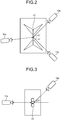
- FIGS. 2 and 3 are each a diagram illustrating exemplary disposition of a plurality of distance sensors. Each disposition is an example in gymnastics but the present invention is applicable to disposition in accordance with other sports and human motion.
- FIG. 2 illustrates exemplary disposition of the distance sensors 10 in a case of still rings. In the example illustrated in FIG. 2 , the three distance sensors 10 are used. As illustrated in FIG. 2 , a main sensor 10a is disposed at a position in the direction in which a large number of players face at still rings 21. A sub sensor 10b is disposed at a position on an obliquely back side of the still rings 21. A sub sensor 10c is disposed at a position on the obliquely back side of the still rings 21 and opposite to the sub sensor 10b.
- FIG. 3 is a diagram illustrating exemplary disposition of a plurality of distance sensors.
- the two distance sensors 10 are used.
- the main sensor 10a is disposed at a position in the direction in which a player faces at a pommel horse 22.
- the sub sensor 10b is disposed at a position on the obliquely back side of the pommel horse 22 and oblique to an axis line of the main sensor 10a at 45° approximately.
- FIGS. 4 and 5 are each a diagram illustrating exemplary occlusion due to an object.
- part of a leg of a person performing on the pommel horse is hidden behind a pommel horse as an object as illustrated in a region 24.
- part of a leg of a person performing on the pommel horse is hidden behind a pommel horse as an object as illustrated in a region 25.
- FIGS. 6 and 7 are each a diagram illustrating exemplary self-occlusion.
- part of an arm of a person performing on the pommel horse is hidden behind a leg as illustrated in a region 26.
- an arm of a person performing on still rings overlaps with the body as illustrated in a region 27.
- the recognition device 100 recognizes the posture and the like of the person 5 based on distance images input from the distance sensors 10.
- the recognition device 100 acquires the positional relation between the distance sensors 10 each of which senses the distance to the person 5 as an object.
- the recognition device 100 provisionally classifies the orientation (posture) of the person 5 as an object relative to each individual distance sensor 10 included in the distance sensors 10 based on sensing data acquired by the individual distance sensor 10.
- the recognition device 100 calculates the likelihood of each combination corresponding to the positional relation between the distance sensors 10 based on a result of the provisional classification of the orientation of the object relative to the individual distance sensor 10.
- the recognition device 100 classifies the orientation (posture) of the person 5 as an object corresponding to each individual distance sensor 10 in accordance with the calculated likelihood of each combination. Accordingly, the recognition device 100 can prevent decrease of the accuracy of classification, in other words, the accuracy of recognition of the orientation (posture) of the person 5 due to the occurrence of occlusion.
- the recognition device 100 acquires the positional relation between the distance sensors 10 each of which senses the distance to the person 5 as an object.
- the recognition device 100 acquires sensing data acquired by each individual distance sensor 10 included in the distance sensors 10.
- the recognition device 100 estimates the three-dimensional position of the skeleton of the object when viewed from each individual distance sensor 10 based on each acquired sensing data and a skeleton recognition dictionary selected in accordance with the orientation of the object relative to the individual distance sensor 10.
- the recognition device 100 determines the three-dimensional position of the skeleton of the object based on a result of the estimation of the three-dimensional position of the skeleton of the object when viewed from each individual distance sensor 10 and the positional relation between the distance sensors 10. Accordingly, the recognition device 100 can prevent recognition accuracy decrease due to the occurrence of occlusion.
- FIG. 8 is a block diagram illustrating an exemplary configuration of the recognition device according to the embodiment.
- the recognition device 100 includes a communication unit 110, a display unit 111, an operation unit 112, a storage unit 120, and a control unit 130.
- the recognition device 100 may include various functional components included in a known computer, for example, functional components such as various input devices and voice output devices in addition to functional components illustrated in FIG. 8 .
- the recognition device 100 may be, for example, a portable personal computer.
- the recognition device 100 may be not only the above-described portable personal computer but also a stationary personal computer.
- the communication unit 110 is achieved by, for example, a network interface card (NIC).
- NIC network interface card
- the communication unit 110 is a communication interface connected with each distance sensor 10 in a wired or wireless manner to govern information communication with the distance sensor 10.
- the display unit 111 is a display device for displaying various kinds of information.
- the display unit 111 is achieved by, for example, a liquid crystal display as a display device.
- the display unit 111 displays various screens including a display screen input from the control unit 130.
- the operation unit 112 is an input device that receives various operations from a user of the recognition device 100.
- the operation unit 112 is achieved by, for example, a keyboard or a mouse as an input device.
- the operation unit 112 outputs an operation input by the user to the control unit 130 as operation information.
- the operation unit 112 may be achieved by, for example, a touch panel as an input device, and the display device of the display unit 111 and the input device of the operation unit 112 may be integrated with each other.
- the storage unit 120 is achieved by, for example, a semiconductor memory element such as a random access memory (RAM) or a flash memory, or a storage device such as a hard disk or an optical disk.
- the storage unit 120 includes a positional relation storage unit 121, a combination storage unit 122, a posture recognition dictionary storage unit 123, and a skeleton recognition dictionary storage unit 124.
- the storage unit 120 stores information used in processing at the control unit 130.
- the positional relation storage unit 121 stores information related to the positional relation between the distance sensors 10.
- the positional relation storage unit 121 stores data of the distance sensors 10 in association with the position coordinates of a main sensor 10 from which most important information (for example, a distance image of the front of a performer) is acquired, or stores position coordinates when integrated with the world coordinates in association with the distance sensors 10.
- the positional relation storage unit 121 also stores angles in a spin direction and a handstand direction that indicate angles when a vector corresponding to each distance sensor 10 is projected onto an xz plane and a yz plane (a z axis is defined to be the distance direction from the sensor to a target, a y axis is defined to be the height direction orthogonal to the z axis, and an x axis is defined to be the horizontal direction).
- the spin direction is defined to be the direction of rotation about an axis from the head of the person 5 as an object toward the legs, in other words, the direction in which the person 5 twists the body while standing straight.
- the handstand direction is defined to be the direction in which the person 5 standing straight is inclined forward, in other words, the direction in which the person 5 performs a forward roll (somersault).
- the combination storage unit 122 stores all combinations of posture numbers calculated based on each angle between the distance sensors 10.
- FIG. 9 is a diagram illustrating an exemplary combination storage unit. As illustrated in FIG. 9 , the combination storage unit 122 includes the items of "spin direction" and "handstand direction". "Spin direction” is information indicating a combination of posture numbers of the distance sensors 10 in the spin direction. "Handstand direction” is information indicating a combination of posture numbers of the distance sensors 10 in the handstand direction.
- FIG. 10 is a diagram illustrating an exemplary posture recognition range and an exemplary posture recognition unit.
- the orientation in other words, posture of the person 5 is recognized in units of 30°.
- recognition of the orientation of the person 5 is referred to as posture recognition.
- the orientation of the person 5 is expressed in a posture number by dividing a circle at each 30° and allocating the posture numbers of "1" to " 12 " in an anticlockwise manner from the front direction of the person 5.
- the posture numbers are divided into groups of four directions, depending on the direction of the person 5.
- Group “0” is a group that corresponds to the front direction and to which Posture numbers "12", “1", and “2” belong.
- Group “1” is a group that corresponds to the right hand direction of the person 5 and to which Posture numbers "9", "10", and “11” belong.
- Group “2” is a group that corresponds to the back direction of the person 5 and to which Posture numbers "6", "7", and “8” belong.
- Group “3” is a group that corresponds to the left hand direction of the person 5 and on which Posture numbers "3", "4", and "5" belong.
- the posture recognition range corresponds to Group “0" to “3": Group “0” corresponds to the posture recognition range in the front direction, Group “1” corresponds to the posture recognition range in the right hand direction, Group “2” corresponds to the posture recognition range in the back direction, and Group “3” corresponds to the posture recognition range in the left hand direction.
- the skeleton recognition dictionary storage unit 124 used in skeleton recognition performs machine learning for a range expanded to the right and left from the posture recognition range by one posture number.
- the range of skeleton recognition learning for the posture recognition range of Group “0” is the range of Posture numbers "11", “12", “1", “2", and “3". This allows the skeleton recognition to be normally performed when some error has occurred to the posture recognition.
- the posture recognition dictionary storage unit 123 stores dictionary information used to determine to which posture a distance image corresponds.
- the posture recognition dictionary storage unit 123 stores, for example, a posture number uniquely identifying a posture, and characteristics of a distance image corresponding to the posture number, in association with each other.
- the posture recognition dictionary storage unit 123 is generated by performing machine learning of various kinds of distance images. In this case, for example, random forest or deep learning may be used as an algorithm of the machine learning.
- the skeleton recognition dictionary storage unit 124 is dictionary information indicating an assumed joint position (skeleton position) for each posture number (dictionary number).
- the skeleton recognition dictionary storage unit 124 associates, for example, a posture number, a distance image corresponding to the posture number, and information (skeleton dictionary information) of a joint position of a person.
- skeleton dictionary information corresponding to each posture number exists.
- the skeleton recognition dictionary storage unit 124 is an exemplary multi-class identification device used to obtain a site label image from the distance image.
- the skeleton recognition dictionary storage unit 124 is generated by performing machine learning on various kinds of distance images corresponding to posture numbers and information of joint positions of a person. In this case, for example, random forest or deep learning may be used as an algorithm of the machine learning.
- the control unit 130 is achieved, for example, as a computer program stored in an internal storage device is executed by a central processing unit (CPU), a graphics processing unit (GPU), or the like by using a RAM as a work area.
- the control unit 130 may be achieved by, for example, an integrated circuit such as an application specific integrated circuit (ASIC) or a field programmable gate array (FPGA).
- ASIC application specific integrated circuit
- FPGA field programmable gate array
- the control unit 130 includes an acquisition unit 131, a calculation unit 132, a first determination unit 133, a posture recognition unit 134, an estimation unit 135, and a second determination unit 136, and achieves or executes functions and effects of information processing described below. Specifically, each processing unit of the control unit 130 executes first recognition processing and second recognition processing.
- the internal configuration of the control unit 130 is not limited to the configuration illustrated in FIG. 8 but may be any other configuration capable of performing the information processing to be described later.
- the acquisition unit 131 receives and acquires the distance image (sensing data) from each distance sensor 10 through the communication unit 110.
- the acquisition unit 131 outputs the acquired distance image to the calculation unit 132, the posture recognition unit 134, and the estimation unit 135.
- the calculation unit 132 converts the distance image of each distance sensor 10 into point group data.
- the point group data is obtained by converting each pixel of the distance image into a point expressed with the three axes of the x, y, and z axes on coordinates with respect to the individual distance sensor 10.
- the calculation unit 132 integrates the point group data of each distance sensor 10 after the conversion into coordinates of one coordinate system.
- FIG. 11 is a diagram illustrating exemplary integration of the point group data of a plurality of distance sensors.
- the calculation unit 132 generates pieces of the point group data based on respective distance images 31a and 31b as outputs from the main sensor 10a and the sub sensor 10b that measure the person 5.
- the calculation unit 132 integrates the generated pieces of the point group data into, for example, the coordinates of the main sensor 10a, thereby generating integrated point group data 32.
- the calculation unit 132 performs positioning of each point group data with the integrated coordinates.
- the calculation unit 132 determines, through calibration, sensor parameters and affine transform matrices for converting the coordinates of each distance sensor 10.
- the calibration is performed by using an instrument selected for the calibration or a general-purpose calibration jig.
- the positioning sensor parameters are ⁇ xrot representing the rotation angle about the x axis, ⁇ yrot representing the rotation angle about the y axis, ⁇ zrot representing the rotation angle about the z axis, t x representing translation along the x axis, t y representing translation along the y axis, and t z representing translation along the z axis.
- the affine transform matrices are Expressions (1) to (4) described below.
- Expression (4) expresses translation.
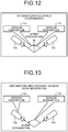
- FIG. 12 is a diagram illustrating an example in which the coordinates of each distance sensor are integrated into the world coordinates.
- the calculation unit 132 integrates the coordinates of the main sensor 10a and the coordinates of the sub sensor 10b into the world coordinates by using sensor parameters 11a and 11b, respectively.
- FIG. 13 is a diagram illustrating an example in which the coordinates of each distance sensor are integrated into the coordinates of the main sensor.
- the calculation unit 132 integrates the coordinates of the main sensor 10a and the coordinates of the sub sensor 10b into the coordinates of the main sensor 10a by using sensor parameters 12a and 12b, respectively. In this case, all sensor parameters 12a corresponding to the main sensor 10a become zero.
- the calculation unit 132 generates inverted affine transform matrices for returning to the original position of each distance sensor 10 from each sensor parameter obtained through the calibration and corresponding to the integrated point group data.
- ⁇ is - ⁇ xrot for the x axis
- ⁇ is - ⁇ yrot for the y axis
- ⁇ is - ⁇ zrot for the z axis.
- the calculation unit 132 calculates a converted vector for each distance sensor 10 by multiplying a unit vector, for example, the z-directional unit vector by the inverted affine transform matrix.
- the calculation unit 132 acquires the spin-direction angle by projecting each converted vector corresponding to each distance sensor 10 onto the xz plane. Accordingly, the calculation unit 132 determines the installation position of each distance sensor 10 on the plane.
- the calculation unit 132 acquires the handstand-direction angle by projecting the converted vector corresponding to each distance sensor 10 onto the yz plane. In other words, the calculation unit 132 determines the relative height and elevation of each distance sensor 10. In this example, it is assumed for simplification that the relative height and elevation are set to be equal between the distance sensors 10 and the vectors corresponding to the respective distance sensors 10 are substantially same.
- the calculation unit 132 stores the spin-direction angle and the handstand-direction angle thus acquired in the positional relation storage unit 121. Having stored the spin-direction angle and the handstand-direction angle in the positional relation storage unit 121, the calculation unit 132 outputs a combination determination instruction to the first determination unit 133.
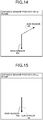
- FIG. 14 is a diagram illustrating an exemplary position of each distance sensor on the xz plane.
- the vectors corresponding to the main sensor 10a and the sub sensor 10b have directions upon reflection of sensor disposition.
- FIG. 15 is a diagram illustrating an exemplary position of each distance sensor on the yz plane. As described above, in the example in FIG. 15 , the vectors corresponding to the main sensor 10a and the sub sensor 10b have substantially same directions.
- the first determination unit 133 refers to the positional relation storage unit 121 and acquires the spin-direction and handstand-direction angles of each distance sensor 10.
- the first determination unit 133 determines the angle between the distance sensors 10, in other words, the angle between the vectors corresponding to the respective distance sensor 10 based on the acquired handstand-direction and spin-direction angles of each distance sensor 10.
- the first determination unit 133 determines all combinations of posture numbers for each of the spin and handstand directions based on the angle between the distance sensors 10.
- the first determination unit 133 stores the determined combinations in the combination storage unit 122.
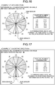
- FIGS. 16 and 17 illustrate an example of determined combinations.
- FIG. 16 is a diagram illustrating all exemplary combinations of posture numbers in the spin direction.
- 12 combinations of “ 1-5 “ , “ 2-6 “ , “ 3-7 “ , ... are determined as all combinations of posture numbers corresponding to the angle between the main sensor 10a and the sub sensor 10b.
- the 12 combinations are possible as the positional relation between the main sensor 10a and the sub sensor 10b.
- FIG. 17 is a diagram illustrating all exemplary combinations posture numbers in the handstand direction.
- 12 combinations of “1-1", “ 2-2 “ , “ 3-3 “ , ... are determined as all combinations of posture numbers corresponding to the angle between the main sensor 10a and the sub sensor 10b.
- the 12 combinations are possible as the positional relation between the main sensor 10a and the sub sensor 10b.
- the first determination unit 133 determines combinations in the same manner when the number of distance sensors 10 is three or larger.
- the calculation unit 132 and the first determination unit 133 are each an exemplary acquisition unit that acquires the positional relation between the distance sensors 10 each of which senses (measures) the distance to the person 5 as an object.
- the acquisition unit in this case may include the acquisition unit 131 that acquires the distance image from each distance sensor 10.
- the distance image corresponding to each distance sensor 10 is input from the acquisition unit 131 to the posture recognition unit 134.
- the posture recognition unit 134 refers to the posture recognition dictionary storage unit 123 and executes the posture recognition for each distance sensor 10 based on the distance image of the distance sensor 10.
- the posture recognition unit 134 calculates, for each combination of posture numbers in the spin and handstand directions, the probability of the orientation (posture) of the object as a result of the posture recognition.
- the posture recognition unit 134 uses, for example, 15 combinations having highest probabilities in 144 combinations since the number of posture numbers in the spin and handstand directions is 12 for each distance sensor 10.
- the combinations of posture numbers in the spin and handstand directions, the probabilities of which are to be used are not limited to highest 15 combinations but may be combinations in an optional number.
- the posture recognition unit 134 calculates, for each of the spin and handstand directions, the likelihood of each combination of the posture numbers of the distance sensors 10 by referring to the combination storage unit 122 and summing the probabilities of the orientation of the object for the combination of the posture numbers of the distance sensors 10.
- the posture recognition unit 134 calculates the likelihood of Combination "2-6" to be "0.7", for example, when the probability of Posture number "2" of the main sensor 10a for Combination "2-6" is "0.3” and the probability of Posture number "6" of the sub sensor 10b for Combination "2-6” is "0.4".
- the posture recognition unit 134 calculates the likelihood of each combination and determines posture numbers of the distance sensors 10 of a combination, the likelihood of which is maximum.
- the posture recognition unit 134 determines the determined posture numbers to be dictionary numbers of the distance sensors 10. Each dictionary number corresponds to a posture number in the skeleton recognition dictionary storage unit 124 and specifies a skeleton recognition dictionary used to estimate the three-dimensional position of the skeleton of the object. The posture recognition unit 134 outputs the determined spin-direction and handstand-direction dictionary numbers of each distance sensor 10 to the estimation unit 135.
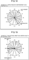
- FIG. 18 is a diagram illustrating exemplary dictionary number determination in the spin direction. For example, when the likelihood "0.7” of Combination "2-6" is maximum in the spin direction as illustrated in FIG. 18 , the dictionary number of the main sensor 10a is determined to be Posture number "2", and the dictionary number of the sub sensor 10b is determined to be Posture number "6".
- FIG. 19 is a diagram illustrating exemplary dictionary number determination in the handstand direction. For example, when the likelihood "0.8" of Combination "10-10" is maximum in the handstand direction as illustrated in FIG. 19 , the dictionary amount of the main sensor 10a and the sub sensor 10b are determined to be Posture number "10".
- FIG. 20 is a diagram illustrating an exemplary posture recognition result in the handstand direction and an exemplary skeleton recognition dictionary selection range.
- the posture recognition result in the handstand direction is classified into four directions of upright, prone, handstand, and supine.
- the skeleton recognition dictionary selection range is increased by one posture number in each of directions expanding from the posture recognition result.
- a skeleton recognition dictionary range 34a corresponds to a posture recognition result 33a for upright
- a skeleton recognition dictionary range 34b corresponds to a posture recognition result 33b for prone.
- a skeleton recognition dictionary range 34c corresponds to a posture recognition result 33c for handstand
- a skeleton recognition dictionary range 34d corresponds to a posture recognition result 33d for supine.
- the increase of each skeleton recognition dictionary range as compared to the corresponding posture recognition result is preparation for error in the posture recognition.
- the vectors corresponding to the main sensor 10a and the sub sensor 10b point to the direction of 0°, in other words, Posture number "1". In this case, the posture recognition result is "upright", and the skeleton recognition dictionary range is "upright".
- FIG. 21 is a diagram illustrating an exemplary the posture recognition result and an exemplary skeleton recognition dictionary selection range in the spin direction.
- the posture recognition result in the spin direction is classified into four directions of front, right, back, and left.
- the skeleton recognition dictionary selection range is increased by one posture number in each of directions expanding from the posture recognition result.
- a skeleton recognition dictionary range 37a corresponds to a posture recognition result 36a for front
- a skeleton recognition dictionary range 37b corresponds to a posture recognition result 36b for right.
- a skeleton recognition dictionary range 37c corresponds to a posture recognition result 36c for back
- a skeleton recognition dictionary range 37d corresponds to a posture recognition result 36d for left.
- the increase of each skeleton recognition dictionary range as compared to the posture recognition result is preparation for error in the posture recognition.
- a vector 39a corresponding to the main sensor 10a points to the direction of 330°, in other words, Posture number "2".
- the posture recognition result is "front”
- the skeleton recognition dictionary range is "front”.
- a vector 39b corresponding to the sub sensor 10b points to the direction of 210°, in other words, Posture number "6”.
- the posture recognition result is "back”
- the skeleton recognition dictionary range is "back”.
- the posture recognition unit 134 provisionally classifies the orientation of the object relative to each individual distance sensor 10 included in the distance sensors 10 into one of a plurality of classifications based on sensing data acquired by the individual distance sensor 10.
- the classifications correspond to posture numbers.
- the posture recognition unit 134 calculates the likelihood of each combination corresponding to the positional relation between the distance sensors 10 based on a result (posture number) of the provisional classification of the orientation of the object relative to each individual distance sensor 10.
- the posture recognition unit 134 classifies the orientation of the object corresponding to each individual distance sensor 10 in accordance with the calculated likelihood of each combination.
- the classified orientation of the object is a dictionary number corresponding to a posture number.
- the posture recognition unit 134 is an exemplary first classification unit that provisionally classifies the orientation of the object, an exemplary calculation unit that calculates the likelihood of each combination, and an exemplary second classification unit that classifies the orientation of the object corresponding to each distance sensor 10 in accordance with the likelihood of each combination.
- the posture recognition unit 134 calculates the likelihood of each combination corresponding to the positional relation between the distance sensors 10 in the direction in which the object handstands and the direction in which the object spins. In addition, the posture recognition unit 134 classifies the orientation of the object corresponding to each individual distance sensor 10 in accordance with likelihood as the sum of the likelihood of each individual distance sensor 10 corresponding to the combination.
- the estimation unit 135 receives inputting of the distance image from the acquisition unit 131 and inputting of the dictionary numbers of each distance sensor 10 in the spin and handstand directions from the posture recognition unit 134.
- the estimation unit 135 refers to the skeleton recognition dictionary storage unit 124 and generates a site label image by using the skeleton recognition dictionary based on the distance image and dictionary numbers of each distance sensor 10.
- the site label image is an image in which a site of the person 5 as an object is labeled based on the distance (depth).
- the estimation unit 135 extracts boundary pixels of each joint site from the generated site label image.
- the estimation unit 135 converts pixels corresponding to boundary pixels of the distance image of each distance sensor 10 into a point group based on the extracted boundary pixels of each joint site, and extracts the boundary point group of each joint site.
- the estimation unit 135 outputs the extracted boundary point group of each joint site for each distance sensor 10 to the second determination unit 136.
- the estimation unit 135 acquires sensing data acquired by each individual distance sensor 10 included in the distance sensors 10.
- the estimation unit 135 estimates the three-dimensional position of the skeleton of the object when viewed from each individual distance sensor 10 based on each acquired sensing data and the skeleton recognition dictionary selected in accordance with the orientation of the object relative to the individual distance sensor 10.
- the estimation unit 135 generates a site label image in which a site of the object is expressed by a site label by using the skeleton recognition dictionary based on the sensing data, and estimates the three-dimensional position of the skeleton of the object based on the site label in the generated site label image.
- the estimation unit 135 estimates the three-dimensional position of the skeleton of the object by using data of the vicinity of the boundary of the site label in the sensing data.
- the estimation unit 135 may output, to the second determination unit 136, a boundary point group obtained by calculating dispersion of the boundary point group of each joint site of each distance sensor 10 and randomly thinning or increasing the boundary point group by using the reciprocal of the calculated dispersion. Specifically, the estimation unit 135 calculates dispersion of data of the vicinity of the boundary for each individual distance sensor 10. The estimation unit 135 estimates the three-dimensional position of the skeleton of the object by using sensing data obtained by randomly thinning or increasing the sensing data of each individual distance sensor 10 by using the reciprocal of the calculated dispersion.
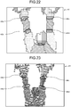
- FIG. 22 is a diagram illustrating exemplary boundary pixels in a site label image.
- this site label image 41 illustrated in FIG. 22 each pixel at the boundary of a site label is extracted as a boundary pixel of a joint site.
- Boundary pixels 42a and 42b correspond to the right wrist and the right elbow, respectively.
- Boundary pixels 42c and 42d correspond to the left wrist and the left elbow, respectively.
- FIG. 23 is a diagram illustrating an exemplary boundary point group of each joint site.
- Point group data 43 illustrated in FIG. 23 is obtained by converting the distance image corresponding to the site label image 41 into the three coordinate axes of the x, y, and z axes.
- a point group corresponding to the extracted boundary pixels of each joint site in FIG. 22 is extracted as the boundary point group of the joint site.
- Boundary point groups 44a and 44b correspond to the boundary pixels 42a and 42b and correspond to the right wrist and the right elbow, respectively.
- Boundary point groups 44c and 44d correspond to the boundary pixels 42c and 42d and correspond to the left wrist and the left elbow, respectively.
- the extracted boundary point group of each joint site of each distance sensor 10 is input from the estimation unit 135 to the second determination unit 136.
- the second determination unit 136 refers to the positional relation storage unit 121 and integrates the extracted boundary point group of each joint site of each distance sensor 10 into the coordinates of the main sensor 10a by using sensor parameters.
- the second determination unit 136 may use the world coordinates as the coordinates into which the integration is performed.
- the second determination unit 136 calculates the barycenter of the integrated boundary point group of each joint site and determines the coordinates of the barycenter to be joint coordinates. In other words, the second determination unit 136 determines the three-dimensional position of the skeleton of the person 5 as an object.
- the second determination unit 136 outputs the determined joint coordinates to, for example, a processing unit or processing device that performs fitting to the distance image.
- the second determination unit 136 may output the determined joint coordinates to, for example, a processing unit or processing device that performs gymnastics scoring or may output the determined joint coordinates as a skeleton model usable for computer graphics (CG) animation.
- CG computer graphics
- the second determination unit 136 may fabricate the determined joint coordinates into, for example, a particular format and output the joint coordinates to an external storage device (not illustrated) or the like.
- the second determination unit 136 may generate a three-dimensional model based on the determined joint coordinates, output the three-dimensional model to the display unit 111, and display the three-dimensional model.
- the second determination unit 136 determines the three-dimensional position of the skeleton of the object based on a result of estimation of the three-dimensional position of the skeleton of the object when viewed from each individual distance sensor 10 and the positional relation between the distance sensors 10. In addition, the second determination unit 136 determines the barycenter of the boundaries of site labels to be a joint position.
- the second determination unit 136 may calculate the barycenter for the boundary point group of each joint site of the distance sensor 10 that has the shortest distance to the person 5 as an object. Specifically, the second determination unit 136 may calculate the barycenter of the boundaries by using a result of estimation of the three-dimensional position of the skeleton when viewed from the distance sensor 10, the distance of which to the object is shortest among the distance sensors 10. The second determination unit 136 may determine, for example, the position (coordinates) of a site such as the center between both shoulders or the crotch based on a plurality of determined joint positions (joint coordinates). For the head, the toes, and the like, the second determination unit 136 may determine the centroid of a site label to be the position (coordinates) of a site corresponding to the site label.
- FIG. 24 is a diagram illustrating exemplary joint coordinates.
- FIG. 24 illustrates a state in which labeling is performed on a person 5a, and each joint position expressed by joint coordinates 45, each site expressed by a centroid 46 of a site label, and position 47 of each site based on a plurality of joint coordinates 45 are determined.
- FIG. 25 is a diagram illustrating an exemplary site label image.
- the site label image of a person 5b illustrated in FIG. 25 is the site label image corresponding to the labeling of the person 5a illustrated in FIG. 24 .
- the persons 5a and 5b are identical to each other although the position of the right hand is different between the persons.
- FIG. 26 is a flowchart illustrating exemplary the first recognition processing according to the embodiment.
- the acquisition unit 131 of the recognition device 100 receives and acquires the distance image from each distance sensor 10.
- the acquisition unit 131 outputs the acquired distance image to the calculation unit 132, the posture recognition unit 134, and the estimation unit 135.
- the calculation unit 132 executes sensor positional relation calculation processing (step S1).
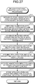
- FIG. 27 is a flowchart illustrating exemplary sensor positional relation calculation processing.
- the calculation unit 132 converts the distance image of each distance sensor 10 into the point group data.
- the calculation unit 132 integrates the converted point group data of each distance sensor 10 into the coordinates of the main sensor 10a (step S11).
- the calculation unit 132 calibrates each point group data with the integrated coordinates.
- the calculation unit 132 determines sensor parameters and affine transform matrices of each distance sensor 10 through the calibration (step S12).
- the calculation unit 132 generates inverted affine transform matrices of each distance sensor 10 from the sensor parameters (step S13).
- the calculation unit 132 calculates the converted vector of each distance sensor 10 by multiplying a unit vector by the corresponding inverted affine transform matrix (step S14).
- the calculation unit 132 acquires the spin-direction angle by projecting each converted vector corresponding to each distance sensor 10 onto the xz plane (step S15). In addition, the calculation unit 132 acquires the handstand-direction angle by projecting the converted vector corresponding to each distance sensor 10 onto the yz plane (step S16). The calculation unit 132 stores the acquired spin-direction and handstand-direction angles in the positional relation storage unit 121 (step S17), outputs a combination determination instruction to the first determination unit 133, and then returns to the original processing. Accordingly, the calculation unit 132 can calculate the positional relation between the distance sensors 10.
- step S2 when the combination determination instruction is input from the calculation unit 132, the first determination unit 133 executes combination determination processing (step S2).
- FIG. 28 is a flowchart illustrating exemplary combination determination processing.
- the first determination unit 133 refers to the positional relation storage unit 121 and acquires the spin-direction and handstand-direction angles of each distance sensor 10. The first determination unit 133 determines the angle between the distance sensors 10 based on the acquired spin-direction and handstand-direction angles of each distance sensor 10 (step S21).
- the first determination unit 133 determines, for each of the spin and handstand directions, all combinations of posture numbers based on the angle between the distance sensors 10 (step S22).
- the first determination unit 133 stores the determined combinations in the combination storage unit 122 (step S23), and returns to the original processing. Accordingly, the first determination unit 133 can determine combinations of posture numbers based on the angle between the distance sensors 10.
- the posture recognition unit 134 executes posture recognition processing (step S3).
- FIG. 29 is a flowchart illustrating exemplary posture recognition processing.
- the posture recognition unit 134 refers to the posture recognition dictionary storage unit 123 and executes the posture recognition for each distance sensor 10 based on the distance image of the distance sensor 10 (step S31).
- the posture recognition unit 134 calculates, for each combination of posture numbers in the spin and handstand directions, the probability of the orientation of the object as a posture recognition result (step S32), and returns to the original processing. Accordingly, the posture recognition unit 134 can recognize the orientation (posture) of the object.
- the posture recognition unit 134 executes dictionary determination processing (step S4).
- FIG. 30 is a flowchart illustrating exemplary dictionary determination processing.
- the posture recognition unit 134 calculates the likelihood of each combination of the posture numbers of the distance sensors 10 by referring to the combination storage unit 122 and summing the probabilities of the orientation of the object for the combination of the posture numbers of the distance sensors 10 in the spin and handstand directions (step S41).
- the posture recognition unit 134 determines posture numbers of the distance sensors 10 of a combination, the likelihood of which is maximum (step S42). The posture recognition unit 134 determines the determined posture numbers to be dictionary numbers of the distance sensors 10 (step S43), and returns to the original processing. Accordingly, the posture recognition unit 134 can determine the dictionary number of the skeleton recognition dictionary used in the skeleton recognition.
- the posture recognition unit 134 outputs the determined dictionary number of each distance sensor 10 to the estimation unit 135 (step S5). Accordingly, as a result of recognition of the posture of the person 5, the recognition device 100 can output the dictionary number of the skeleton recognition dictionary used for each distance sensor 10. Thus, the recognition device 100 can prevent decrease of the accuracy of classification of the orientation of the person 5 due to the occurrence of occlusion, in other words, the accuracy of recognition. In addition, the recognition device 100 can fast integrate the point group data based on the distance images of the distance sensors 10 and can accurately perform the posture recognition. In addition, the recognition device 100 can improve the accuracy of the posture recognition as compared to a case in which the number of distance sensors 10 is one. When the position of each distance sensor 10 is not changed, the positional relation calculation processing and the combination determination processing may be omitted in repetitive execution of the first recognition processing.
- FIG. 31 is a flowchart illustrating exemplary second recognition processing according to the embodiment.
- the estimation unit 135 of the recognition device 100 receives inputting of each distance image from the acquisition unit 131 and inputting of the dictionary number of each distance sensor 10 from the posture recognition unit 134.
- the estimation unit 135 refers to the skeleton recognition dictionary storage unit 124 and generates a site label image by using the skeleton recognition dictionary based on the distance image and dictionary number of each distance sensor 10 (step S101).
- the estimation unit 135 extracts boundary pixels of each joint site from the generated site label image (step S102).
- the estimation unit 135 converts pixels corresponding to boundary pixels of the distance image of each distance sensor 10 into a point group based on the extracted boundary pixels of each joint site, and extracts the boundary point group of the joint site (step S103).
- the estimation unit 135 outputs the extracted boundary point group of each joint site of each distance sensor 10 to the second determination unit 136.
- the second determination unit 136 refers to the positional relation storage unit 121 and integrates the extracted boundary point group of each joint site of each distance sensor 10, which is input from the estimation unit 135, into the coordinates of the main sensor 10a by using sensor parameters (step S104).
- the second determination unit 136 calculates the barycenter of the integrated boundary point group of each joint site and determines the coordinates of the barycenter to be joint coordinates (step S105).
- the second determination unit 136 outputs the determined joint coordinates to, for example, another processing unit or processing device (step S106). Accordingly, the recognition device 100 can prevent recognition accuracy decrease due to the occurrence of occlusion.
- the point group increase due to the distance sensors (n distance sensors) 10 can improve, by 1/sqrt(n) at maximum, the accuracy of fitting at a later stage in the skeleton recognition.
- the recognition device 100 can output a result of fast and highly accurate skeleton recognition.
- the recognition device 100 acquires the positional relation between the distance sensors 10 each of which senses the distance to the object.
- the recognition device 100 provisionally classifies the orientation of the object relative to each individual distance sensor 10 included in the distance sensors 10 into one of a plurality of classifications based on sensing data acquired by the individual distance sensor 10.
- the recognition device 100 calculates the likelihood of each combination corresponding to the positional relation between the distance sensors 10 based on result of the provisional classification of the orientation of the object relative to the individual distance sensor 10.
- the recognition device 100 classifies the orientation of the object corresponding to each individual sensor in accordance with the calculated likelihood of each combination. As a result, the recognition device 100 can prevent recognition accuracy decrease due to the occurrence of occlusion.
- the recognition device 100 calculates the likelihood of each combination corresponding to the positional relation between the distance sensors 10 in the direction in which the object handstands and the direction in which the object spins. As a result, the recognition device 100 can prevent recognition accuracy decrease due to the occurrence of occlusion.
- the recognition device 100 classifies the orientation of the object corresponding to each individual distance sensor 10 in accordance with likelihood as the sum of the likelihood of each individual distance sensor 10 corresponding to the combination. As a result, the accuracy of classification of the orientation of the object at each distance sensor 10 can be improved.
- the recognition device 100 acquires the positional relation between the distance sensors 10 that sense distance to the object. In addition, the recognition device 100 acquires sensing data acquired by each individual distance sensor 10 included in the distance sensors 10. In addition, the recognition device 100 estimates the three-dimensional position of the skeleton of the object when viewed from each individual distance sensor 10 based on each acquired sensing data and the skeleton recognition dictionary selected in accordance with the orientation of the object relative to the individual distance sensor 10. In addition, the recognition device 100 determines the three-dimensional position of the skeleton of the object based on a result of the estimation of the three-dimensional position of the skeleton of the object when viewed from each individual distance sensor 10 and the positional relation between the distance sensors 10. As a result, the recognition device 100 can prevent recognition accuracy decrease due to the occurrence of occlusion.
- the recognition device 100 generates, based on the sensing data, a site label image in which a site of the object is expressed by a site label by using the skeleton recognition dictionary. In addition, the recognition device 100 estimates the three-dimensional position of the skeleton of the object based on the site label in the generated site label image. As a result, the three-dimensional position of the skeleton of the object can be estimated for each distance sensor 10.
- the recognition device 100 estimates the three-dimensional position of the skeleton of the object by using data of the vicinity of the boundary of the site label in the sensing data. As a result, the recognition device 100 can reduce the processing amount of conversion from the distance image to the point group data.
- the recognition device 100 determines the barycenter of the boundaries of the site labels to be a joint position. As a result, the recognition device 100 can determine the joint position.
- the recognition device 100 calculates the barycenter of the boundaries by using a result of estimation of the three-dimensional position of the skeleton when viewed from the distance sensor 10, the distance of which to the object is shortest among the distance sensors 10. As a result, the recognition device 100 can improve the accuracy of calculation of the barycenter of the boundaries.
- the recognition device 100 calculates dispersion of data of the vicinity of the boundary for each individual distance sensor 10. In addition, the recognition device 100 estimates the three-dimensional position of the skeleton of the object by using sensing data obtained by randomly thinning or increasing the sensing data of each individual distance sensor 10 by using the reciprocal of the calculated dispersion. As a result, the recognition device 100 can improve the speed or accuracy of calculation of the barycenter of the boundaries.
- the recognition device 100 determines the position of the site based on the determined joint positions. As a result, the recognition device 100 can determine the position of the site to be a position other than the barycenter of the boundaries of the site labels, such as the center between both shoulders.
- the recognition device 100 determines the position of the site corresponding to the site label to be the centroid of the site label. As a result, the recognition device 100 can determine the position of the site to be a position, such as the head, other than the barycenter of the boundaries of the site labels.
- the second recognition processing of performing the skeleton recognition is executed by using a result of the first recognition processing of performing the posture recognition, but the present invention is not limited thereto.
- the skeleton recognition may be performed by executing the second recognition processing according to the present embodiment based on a result obtained by using another method in the posture recognition.
- the skeleton recognition may be performed by using another method based on a result of the posture recognition performed by executing the first recognition processing according to the present embodiment.
- the person 5 performing gymnastics is measured when the posture recognition and the skeleton recognition are performed, but the present invention is not limited thereto.
- the present invention is also applicable to check of movement in another scoring sport such as figure skating and in rehabilitation, and applicable to form analysis in baseball, golf, and the like.
- the two axes in the spin and handstand directions of the person 5 are used, but the present invention is not limited thereto.
- three axes additionally including a cartwheel direction may be used, or polar coordinates may be used in expression with the orientation of the backbone of the person 5 and three angles of rotation of a line connecting the shoulders.
- All or an optional part of various kinds of processing functions performed by each device may be executed by a CPU (or GPU).
- all or an optional part of the various kinds of processing functions may be executed by a computer program analyzed and executed by the CPU (or GPU) or by wired logic hardware.
- FIG. 32 is a diagram illustrating an exemplary computer that executes a recognition program.
- a computer 200 includes a CPU 201 that executes various kinds of arithmetic processing, an input device 202 that receives data input, and a monitor 203.
- the computer 200 also includes a medium reading device 204 that reads a computer program and the like from a storage medium, an interface device 205 for connection with various devices, and a communication device 206 for connection with each distance sensor 10, another information processing device, or the like in a wired or wireless manner.
- the computer 200 also includes a RAM 207 that temporarily stores various kinds of information, and a hard disk device 208.
- the devices 201 to 208 are connected with a bus 209.
- the hard disk device 208 stores the recognition program having functions same as those of the processing units of the acquisition unit 131, the calculation unit 132, the first determination unit 133, the posture recognition unit 134, the estimation unit 135, and the second determination unit 136 illustrated in FIG. 8 .
- the hard disk device 208 also stores various kinds of data for achieving the positional relation storage unit 121, the combination storage unit 122, the posture recognition dictionary storage unit 123, the skeleton recognition dictionary storage unit 124, and the recognition program.
- the input device 202 receives inputting of various kinds of information such as operation information from a user of the computer 200.
- the monitor 203 displays various screens such as a display screen to the user of the computer 200.
- the interface device 205 is connected with, for example, a printing device.
- the communication device 206 has functions same as those of the communication unit 110 illustrated in FIG. 8 , is connected with each distance sensor 10 or another information processing device, and communicates various kinds of information with the distance sensor 10 or the other information processing device.
- the CPU 201 performs various kinds of processing by reading each computer program stored in the hard disk device 208, loading the computer program onto the RAM 207, and executing the computer program. These computer programs can cause the computer 200 to function as the acquisition unit 131, the calculation unit 132, the first determination unit 133, the posture recognition unit 134, the estimation unit 135, and the second determination unit 136 illustrated in FIG. 8 .
- the above-described recognition program does not necessarily need to be stored in the hard disk device 208.
- the program may be stored in a storage medium readable by the computer 200 and may be read and executed by the computer 200.
- Examples of the storage medium readable by the computer 200 include portable recording media such as a CD-ROM, a digital versatile disc (DVD), and a universal serial bus (USB) memory, a semiconductor memory such as a flash memory, and a hard disk drive.
- the recognition program may be stored in a device connected with a network such as a public line, the Internet, a LAN, or the like and may be read from the network and executed by the computer 200.
Landscapes
- Health & Medical Sciences (AREA)
- Engineering & Computer Science (AREA)
- Life Sciences & Earth Sciences (AREA)
- Physics & Mathematics (AREA)
- General Health & Medical Sciences (AREA)
- Computer Vision & Pattern Recognition (AREA)
- Veterinary Medicine (AREA)
- Animal Behavior & Ethology (AREA)
- Public Health (AREA)
- Surgery (AREA)
- Molecular Biology (AREA)
- Medical Informatics (AREA)
- Heart & Thoracic Surgery (AREA)
- Biomedical Technology (AREA)
- Pathology (AREA)
- Biophysics (AREA)
- General Physics & Mathematics (AREA)
- Theoretical Computer Science (AREA)
- Physiology (AREA)
- Oral & Maxillofacial Surgery (AREA)
- Dentistry (AREA)
- Multimedia (AREA)
- Psychiatry (AREA)
- Artificial Intelligence (AREA)
- Human Computer Interaction (AREA)
- Social Psychology (AREA)
- Physical Education & Sports Medicine (AREA)
- Evolutionary Computation (AREA)
- Nuclear Medicine, Radiotherapy & Molecular Imaging (AREA)
- Radiology & Medical Imaging (AREA)
- Signal Processing (AREA)
- Fuzzy Systems (AREA)
- Geometry (AREA)
- Mathematical Physics (AREA)
- Image Analysis (AREA)
Abstract
Description
- The present invention relates to a recognition program, a recognition method, and a recognition device.
- A conventionally available device recognizes the posture and motion of a person based on a distance image (hereinafter, also referred to as a depth image) output from a distance sensor (hereinafter, also referred to as a depth sensor) that senses the distance to the person. This device labels a site of the person based on the distance image output from, for example, one distance sensor. Subsequently, the device extracts, based on each labeled site, a skeleton model having a three-dimensional skeleton position. Thereafter, the device recognizes the posture and motion of the person based on the extracted skeleton model.
- Patent Document 1:
U.S. Patent No. 2010/0197390 - However, when the posture and motion of a person are to be recognized by using one distance sensor, occlusion can occur in which part of the person is hidden by, for example, an object or a site of the person. When the occlusion occurs, the accuracy of three-dimensional recognition of the skeleton of the person decreases, and it becomes difficult to recognize complicate motion. Thus, the accuracy of recognition of the skeleton of the person or the like decreases due to the occurrence of the occlusion.
- It is an object of the present invention to provide a recognition program, a recognition method, and a recognition device that can prevent recognition accuracy decrease due to the occurrence of occlusion.
- In one aspect, a recognition program causes a computer to execute a process of acquiring positional relation between a plurality of sensors each of which senses a distance to an object. The recognition program causes the computer to execute a process of provisionally classifying an orientation of the object relative to each individual sensor included in the sensors into one of a plurality of classifications based on sensing data acquired by the individual sensor. The recognition program causes the computer to execute a process of calculating likelihood of each combination corresponding to the positional relation between the sensors based on a result of provisional classification of the orientation of the object relative to the individual sensor. The recognition program causes the computer to execute a process of classifying the orientation of the object corresponding to each individual sensor in accordance with the calculated likelihood of each combination.
- Recognition accuracy decrease due to the occurrence of occlusion can be prevented.
-
-
FIG. 1 is a diagram illustrating an exemplary configuration of a recognition system according to an embodiment. -
FIG. 2 is a diagram illustrating exemplary disposition of a plurality of distance sensors. -
FIG. 3 is a diagram illustrating exemplary disposition of a plurality of distance sensors. -
FIG. 4 is a diagram illustrating exemplary occlusion due to an object. -
FIG. 5 is a diagram illustrating exemplary occlusion due to an object. -
FIG. 6 is a diagram illustrating exemplary self-occlusion. -
FIG. 7 is a diagram illustrating exemplary self-occlusion. -
FIG. 8 is a block diagram illustrating an exemplary configuration of a recognition device according to the embodiment. -
FIG. 9 is a diagram illustrating an exemplary combination storage unit. -
FIG. 10 is a diagram illustrating an exemplary posture recognition range and an exemplary posture recognition unit. -
FIG. 11 is a diagram illustrating exemplary integration of point group data of a plurality of distance sensors. -
FIG. 12 is a diagram illustrating exemplary integration of the coordinates of each distance sensor with the world coordinates. -
FIG. 13 is a diagram illustrating exemplary integration of the coordinates of each distance sensor with the coordinates of a main sensor. -
FIG. 14 is a diagram illustrating an exemplary position of each distance sensor on an xz plane. -
FIG. 15 is a diagram illustrating an exemplary position of each distance sensor on a yz plane. -
FIG. 16 is a diagram illustrating all exemplary combinations of posture numbers in a spin direction. -
FIG. 17 is a diagram illustrating all exemplary combinations of posture numbers in a handstand direction. -
FIG. 18 is a diagram illustrating exemplary dictionary number determination in the spin direction. -
FIG. 19 is a diagram illustrating exemplary dictionary number determination in the handstand direction. -
FIG. 20 is a diagram illustrating an exemplary posture recognition result in the handstand direction and an exemplary skeleton recognition dictionary selection range. -
FIG. 21 is a diagram illustrating an exemplary posture recognition result in the spin direction and an exemplary skeleton recognition dictionary selection range. -
FIG. 22 is a diagram illustrating exemplary boundary pixels in a site label image. -
FIG. 23 is a diagram illustrating an exemplary boundary point group of each joint site. -
FIG. 24 is a diagram illustrating exemplary joint coordinates. -
FIG. 25 is a diagram illustrating an exemplary site label image. -
FIG. 26 is a flowchart illustrating exemplary first recognition processing according to the embodiment. -
FIG. 27 is a flowchart illustrating exemplary sensor positional relation calculation processing. -
FIG. 28 is a flowchart illustrating exemplary combination determination processing. -
FIG. 29 is a flowchart illustrating exemplary posture recognition processing. -
FIG. 30 is a flowchart illustrating exemplary dictionary determination processing. -
FIG. 31 is a flowchart illustrating exemplary second recognition processing according to the embodiment. -
FIG. 32 is a diagram illustrating an exemplary computer that executes a recognition program. - An embodiment of a recognition program, a recognition method, and a recognition device disclosed by the present application will be described below in detail with reference to the accompanying drawings. The present embodiment does not limit the disclosed technology. The embodiment below may be combined as appropriate without inconsistency.
-
FIG. 1 is a diagram illustrating an exemplary configuration of a recognition system according to an embodiment. Thisrecognition system 1 illustrated inFIG. 1 includesdistance sensors recognition device 100. In the following description, thedistance sensors distance sensors 10 when not distinguished from each other. The number ofdistance sensors 10 in therecognition system 1 is not limited, but any optional number of a plurality ofdistance sensors 10 may be included. Therecognition device 100 and each of thedistance sensors - The
recognition system 1 is an exemplary system in which aperson 5 as an object is measured by eachdistance sensor 10 and therecognition device 100 recognizes the posture and the like of theperson 5 based on a result of the measurement. - The
distance sensor 10 measures (senses), for each pixel, the distance to a subject by using an infrared laser or the like, and outputs a distance image of, for example, 320×240 pixels. The distance image includes the distance and angle to each pixel. Thus, the distance image is a depth image indicating the depth of an object when viewed from the distance sensor (depth sensor) 10. Thedistance sensor 10 measures the distance to a subject (object) at, for example, substantially 15 m apart. - The following describes disposition of the
distance sensors 10 with reference toFIGS. 2 and 3. FIGS. 2 and 3 are each a diagram illustrating exemplary disposition of a plurality of distance sensors. Each disposition is an example in gymnastics but the present invention is applicable to disposition in accordance with other sports and human motion.FIG. 2 illustrates exemplary disposition of thedistance sensors 10 in a case of still rings. In the example illustrated inFIG. 2 , the threedistance sensors 10 are used. As illustrated inFIG. 2 , amain sensor 10a is disposed at a position in the direction in which a large number of players face at still rings 21. Asub sensor 10b is disposed at a position on an obliquely back side of the still rings 21. Asub sensor 10c is disposed at a position on the obliquely back side of the still rings 21 and opposite to thesub sensor 10b. -
FIG. 3 is a diagram illustrating exemplary disposition of a plurality of distance sensors. In the example illustrated inFIG. 3 , the twodistance sensors 10 are used. As illustrated inFIG. 3 , themain sensor 10a is disposed at a position in the direction in which a player faces at apommel horse 22. Thesub sensor 10b is disposed at a position on the obliquely back side of thepommel horse 22 and oblique to an axis line of themain sensor 10a at 45° approximately. - The following describes occlusion with reference to
FIGS. 4 to 7 .FIGS. 4 and 5 are each a diagram illustrating exemplary occlusion due to an object. In the occlusion illustrated inFIG. 4 , part of a leg of a person performing on the pommel horse is hidden behind a pommel horse as an object as illustrated in aregion 24. Similarly, in the occlusion illustrated inFIG. 5 , part of a leg of a person performing on the pommel horse is hidden behind a pommel horse as an object as illustrated in aregion 25. -
FIGS. 6 and 7 are each a diagram illustrating exemplary self-occlusion. In the occlusion illustrated inFIG. 6 , part of an arm of a person performing on the pommel horse is hidden behind a leg as illustrated in aregion 26. In the occlusion illustrated inFIG. 7 , an arm of a person performing on still rings overlaps with the body as illustrated in aregion 27. - In
FIG. 1 , therecognition device 100 recognizes the posture and the like of theperson 5 based on distance images input from thedistance sensors 10. Therecognition device 100 acquires the positional relation between thedistance sensors 10 each of which senses the distance to theperson 5 as an object. Therecognition device 100 provisionally classifies the orientation (posture) of theperson 5 as an object relative to eachindividual distance sensor 10 included in thedistance sensors 10 based on sensing data acquired by theindividual distance sensor 10. Therecognition device 100 calculates the likelihood of each combination corresponding to the positional relation between thedistance sensors 10 based on a result of the provisional classification of the orientation of the object relative to theindividual distance sensor 10. Therecognition device 100 classifies the orientation (posture) of theperson 5 as an object corresponding to eachindividual distance sensor 10 in accordance with the calculated likelihood of each combination. Accordingly, therecognition device 100 can prevent decrease of the accuracy of classification, in other words, the accuracy of recognition of the orientation (posture) of theperson 5 due to the occurrence of occlusion. - The
recognition device 100 acquires the positional relation between thedistance sensors 10 each of which senses the distance to theperson 5 as an object. Therecognition device 100 acquires sensing data acquired by eachindividual distance sensor 10 included in thedistance sensors 10. Therecognition device 100 estimates the three-dimensional position of the skeleton of the object when viewed from eachindividual distance sensor 10 based on each acquired sensing data and a skeleton recognition dictionary selected in accordance with the orientation of the object relative to theindividual distance sensor 10. Therecognition device 100 determines the three-dimensional position of the skeleton of the object based on a result of the estimation of the three-dimensional position of the skeleton of the object when viewed from eachindividual distance sensor 10 and the positional relation between thedistance sensors 10. Accordingly, therecognition device 100 can prevent recognition accuracy decrease due to the occurrence of occlusion. - The following describes a functional configuration of the
recognition device 100 with reference toFIG. 8. FIG. 8 is a block diagram illustrating an exemplary configuration of the recognition device according to the embodiment. As illustrated inFIG. 8 , therecognition device 100 includes acommunication unit 110, a display unit 111, anoperation unit 112, astorage unit 120, and acontrol unit 130. Therecognition device 100 may include various functional components included in a known computer, for example, functional components such as various input devices and voice output devices in addition to functional components illustrated inFIG. 8 . Therecognition device 100 may be, for example, a portable personal computer. Therecognition device 100 may be not only the above-described portable personal computer but also a stationary personal computer. - The
communication unit 110 is achieved by, for example, a network interface card (NIC). Thecommunication unit 110 is a communication interface connected with eachdistance sensor 10 in a wired or wireless manner to govern information communication with thedistance sensor 10. - The display unit 111 is a display device for displaying various kinds of information. The display unit 111 is achieved by, for example, a liquid crystal display as a display device. The display unit 111 displays various screens including a display screen input from the
control unit 130. - The
operation unit 112 is an input device that receives various operations from a user of therecognition device 100. Theoperation unit 112 is achieved by, for example, a keyboard or a mouse as an input device. Theoperation unit 112 outputs an operation input by the user to thecontrol unit 130 as operation information. Theoperation unit 112 may be achieved by, for example, a touch panel as an input device, and the display device of the display unit 111 and the input device of theoperation unit 112 may be integrated with each other. - The
storage unit 120 is achieved by, for example, a semiconductor memory element such as a random access memory (RAM) or a flash memory, or a storage device such as a hard disk or an optical disk. Thestorage unit 120 includes a positionalrelation storage unit 121, acombination storage unit 122, a posture recognitiondictionary storage unit 123, and a skeleton recognition dictionary storage unit 124. Thestorage unit 120 stores information used in processing at thecontrol unit 130. - The positional
relation storage unit 121 stores information related to the positional relation between thedistance sensors 10. The positionalrelation storage unit 121 stores data of thedistance sensors 10 in association with the position coordinates of amain sensor 10 from which most important information (for example, a distance image of the front of a performer) is acquired, or stores position coordinates when integrated with the world coordinates in association with thedistance sensors 10. The positionalrelation storage unit 121 also stores angles in a spin direction and a handstand direction that indicate angles when a vector corresponding to eachdistance sensor 10 is projected onto an xz plane and a yz plane (a z axis is defined to be the distance direction from the sensor to a target, a y axis is defined to be the height direction orthogonal to the z axis, and an x axis is defined to be the horizontal direction). The spin direction is defined to be the direction of rotation about an axis from the head of theperson 5 as an object toward the legs, in other words, the direction in which theperson 5 twists the body while standing straight. The handstand direction is defined to be the direction in which theperson 5 standing straight is inclined forward, in other words, the direction in which theperson 5 performs a forward roll (somersault). - The
combination storage unit 122 stores all combinations of posture numbers calculated based on each angle between thedistance sensors 10.FIG. 9 is a diagram illustrating an exemplary combination storage unit. As illustrated inFIG. 9 , thecombination storage unit 122 includes the items of "spin direction" and "handstand direction". "Spin direction" is information indicating a combination of posture numbers of thedistance sensors 10 in the spin direction. "Handstand direction" is information indicating a combination of posture numbers of thedistance sensors 10 in the handstand direction. - The following describes posture numbers with reference to
FIG. 10. FIG. 10 is a diagram illustrating an exemplary posture recognition range and an exemplary posture recognition unit. As illustrated inFIG. 10 , in the present embodiment, the orientation, in other words, posture of theperson 5 is recognized in units of 30°. In the following description, recognition of the orientation of theperson 5 is referred to as posture recognition. - In the present embodiment, the orientation of the
person 5 is expressed in a posture number by dividing a circle at each 30° and allocating the posture numbers of "1" to "12" in an anticlockwise manner from the front direction of theperson 5. The posture numbers are divided into groups of four directions, depending on the direction of theperson 5. Group "0" is a group that corresponds to the front direction and to which Posture numbers "12", "1", and "2" belong. Group "1" is a group that corresponds to the right hand direction of theperson 5 and to which Posture numbers "9", "10", and "11" belong. Group "2" is a group that corresponds to the back direction of theperson 5 and to which Posture numbers "6", "7", and "8" belong. Group "3" is a group that corresponds to the left hand direction of theperson 5 and on which Posture numbers "3", "4", and "5" belong. - In the example in
FIG. 10 , the posture recognition range corresponds to Group "0" to "3": Group "0" corresponds to the posture recognition range in the front direction, Group "1" corresponds to the posture recognition range in the right hand direction, Group "2" corresponds to the posture recognition range in the back direction, and Group "3" corresponds to the posture recognition range in the left hand direction. The skeleton recognition dictionary storage unit 124 used in skeleton recognition performs machine learning for a range expanded to the right and left from the posture recognition range by one posture number. For example, the range of skeleton recognition learning for the posture recognition range of Group "0" is the range of Posture numbers "11", "12", "1", "2", and "3". This allows the skeleton recognition to be normally performed when some error has occurred to the posture recognition. - As illustrated in
FIG. 8 , the posture recognitiondictionary storage unit 123 stores dictionary information used to determine to which posture a distance image corresponds. The posture recognitiondictionary storage unit 123 stores, for example, a posture number uniquely identifying a posture, and characteristics of a distance image corresponding to the posture number, in association with each other. The posture recognitiondictionary storage unit 123 is generated by performing machine learning of various kinds of distance images. In this case, for example, random forest or deep learning may be used as an algorithm of the machine learning. - The skeleton recognition dictionary storage unit 124 is dictionary information indicating an assumed joint position (skeleton position) for each posture number (dictionary number). The skeleton recognition dictionary storage unit 124 associates, for example, a posture number, a distance image corresponding to the posture number, and information (skeleton dictionary information) of a joint position of a person. Although not illustrated, it is assumed that skeleton dictionary information corresponding to each posture number exists. Specifically, the skeleton recognition dictionary storage unit 124 is an exemplary multi-class identification device used to obtain a site label image from the distance image. The skeleton recognition dictionary storage unit 124 is generated by performing machine learning on various kinds of distance images corresponding to posture numbers and information of joint positions of a person. In this case, for example, random forest or deep learning may be used as an algorithm of the machine learning.
- The
control unit 130 is achieved, for example, as a computer program stored in an internal storage device is executed by a central processing unit (CPU), a graphics processing unit (GPU), or the like by using a RAM as a work area. Alternatively, thecontrol unit 130 may be achieved by, for example, an integrated circuit such as an application specific integrated circuit (ASIC) or a field programmable gate array (FPGA). - The
control unit 130 includes anacquisition unit 131, acalculation unit 132, afirst determination unit 133, a posture recognition unit 134, anestimation unit 135, and asecond determination unit 136, and achieves or executes functions and effects of information processing described below. Specifically, each processing unit of thecontrol unit 130 executes first recognition processing and second recognition processing. The internal configuration of thecontrol unit 130 is not limited to the configuration illustrated inFIG. 8 but may be any other configuration capable of performing the information processing to be described later. - The
acquisition unit 131 receives and acquires the distance image (sensing data) from eachdistance sensor 10 through thecommunication unit 110. Theacquisition unit 131 outputs the acquired distance image to thecalculation unit 132, the posture recognition unit 134, and theestimation unit 135. - When the distance image is input from the
acquisition unit 131, thecalculation unit 132 converts the distance image of eachdistance sensor 10 into point group data. The point group data is obtained by converting each pixel of the distance image into a point expressed with the three axes of the x, y, and z axes on coordinates with respect to theindividual distance sensor 10. Thecalculation unit 132 integrates the point group data of eachdistance sensor 10 after the conversion into coordinates of one coordinate system. - The following describes the integration of the point group data with reference to
FIGS. 11 to 13 .FIG. 11 is a diagram illustrating exemplary integration of the point group data of a plurality of distance sensors. As illustrated inFIG. 11 , thecalculation unit 132 generates pieces of the point group data based onrespective distance images 31a and 31b as outputs from themain sensor 10a and thesub sensor 10b that measure theperson 5. Thecalculation unit 132 integrates the generated pieces of the point group data into, for example, the coordinates of themain sensor 10a, thereby generating integratedpoint group data 32. - At the time of integrating the point group data, the
calculation unit 132 performs positioning of each point group data with the integrated coordinates. Thecalculation unit 132 determines, through calibration, sensor parameters and affine transform matrices for converting the coordinates of eachdistance sensor 10. The calibration is performed by using an instrument selected for the calibration or a general-purpose calibration jig. - The positioning sensor parameters are θxrot representing the rotation angle about the x axis, θyrot representing the rotation angle about the y axis, θzrot representing the rotation angle about the z axis, tx representing translation along the x axis, ty representing translation along the y axis, and tz representing translation along the z axis. The affine transform matrices are Expressions (1) to (4) described below. Expression (1) expresses rotation about the x axis with θ = θxrot. Expression (2) expresses rotation about the y axis with θ = θyrot. Expression (3) expresses rotation about the z axis with θ = θzrot. Expression (4) expresses translation.
[Mathematical 1]


-
FIG. 12 is a diagram illustrating an example in which the coordinates of each distance sensor are integrated into the world coordinates. In the example inFIG. 12 , thecalculation unit 132 integrates the coordinates of themain sensor 10a and the coordinates of thesub sensor 10b into the world coordinates by usingsensor parameters -
FIG. 13 is a diagram illustrating an example in which the coordinates of each distance sensor are integrated into the coordinates of the main sensor. In the example inFIG. 13 , thecalculation unit 132 integrates the coordinates of themain sensor 10a and the coordinates of thesub sensor 10b into the coordinates of themain sensor 10a by usingsensor parameters sensor parameters 12a corresponding to themain sensor 10a become zero. - Subsequently, the
calculation unit 132 generates inverted affine transform matrices for returning to the original position of eachdistance sensor 10 from each sensor parameter obtained through the calibration and corresponding to the integrated point group data. In this case, θ is -θxrot for the x axis, θ is -θyrot for the y axis, and θ is -θzrot for the z axis. - The
calculation unit 132 calculates a converted vector for eachdistance sensor 10 by multiplying a unit vector, for example, the z-directional unit vector by the inverted affine transform matrix. Thecalculation unit 132 acquires the spin-direction angle by projecting each converted vector corresponding to eachdistance sensor 10 onto the xz plane. Accordingly, thecalculation unit 132 determines the installation position of eachdistance sensor 10 on the plane. - In addition, the
calculation unit 132 acquires the handstand-direction angle by projecting the converted vector corresponding to eachdistance sensor 10 onto the yz plane. In other words, thecalculation unit 132 determines the relative height and elevation of eachdistance sensor 10. In this example, it is assumed for simplification that the relative height and elevation are set to be equal between thedistance sensors 10 and the vectors corresponding to therespective distance sensors 10 are substantially same. Thecalculation unit 132 stores the spin-direction angle and the handstand-direction angle thus acquired in the positionalrelation storage unit 121. Having stored the spin-direction angle and the handstand-direction angle in the positionalrelation storage unit 121, thecalculation unit 132 outputs a combination determination instruction to thefirst determination unit 133. - The following describes the vector corresponding to the position of each
distance sensor 10 with reference toFIGS. 14 and 15. FIG. 14 is a diagram illustrating an exemplary position of each distance sensor on the xz plane. In the example inFIG. 14 , the vectors corresponding to themain sensor 10a and thesub sensor 10b have directions upon reflection of sensor disposition.FIG. 15 is a diagram illustrating an exemplary position of each distance sensor on the yz plane. As described above, in the example inFIG. 15 , the vectors corresponding to themain sensor 10a and thesub sensor 10b have substantially same directions. - In
FIG. 8 , when the combination determination instruction is input from thecalculation unit 132, thefirst determination unit 133 refers to the positionalrelation storage unit 121 and acquires the spin-direction and handstand-direction angles of eachdistance sensor 10. Thefirst determination unit 133 determines the angle between thedistance sensors 10, in other words, the angle between the vectors corresponding to therespective distance sensor 10 based on the acquired handstand-direction and spin-direction angles of eachdistance sensor 10. - The
first determination unit 133 determines all combinations of posture numbers for each of the spin and handstand directions based on the angle between thedistance sensors 10. Thefirst determination unit 133 stores the determined combinations in thecombination storage unit 122. -
FIGS. 16 and 17 illustrate an example of determined combinations.FIG. 16 is a diagram illustrating all exemplary combinations of posture numbers in the spin direction. In the example inFIG. 16 ,12 combinations of "1-5", "2-6", "3-7", ... are determined as all combinations of posture numbers corresponding to the angle between themain sensor 10a and thesub sensor 10b. The 12 combinations are possible as the positional relation between themain sensor 10a and thesub sensor 10b. -
FIG. 17 is a diagram illustrating all exemplary combinations posture numbers in the handstand direction. In the example inFIG. 17 ,12 combinations of "1-1", "2-2", "3-3", ... are determined as all combinations of posture numbers corresponding to the angle between themain sensor 10a and thesub sensor 10b. The 12 combinations are possible as the positional relation between themain sensor 10a and thesub sensor 10b. Thefirst determination unit 133 determines combinations in the same manner when the number ofdistance sensors 10 is three or larger. - In this manner, the
calculation unit 132 and thefirst determination unit 133 are each an exemplary acquisition unit that acquires the positional relation between thedistance sensors 10 each of which senses (measures) the distance to theperson 5 as an object. The acquisition unit in this case may include theacquisition unit 131 that acquires the distance image from eachdistance sensor 10. - In
FIG. 8 , the distance image corresponding to eachdistance sensor 10 is input from theacquisition unit 131 to the posture recognition unit 134. The posture recognition unit 134 refers to the posture recognitiondictionary storage unit 123 and executes the posture recognition for eachdistance sensor 10 based on the distance image of thedistance sensor 10. The posture recognition unit 134 calculates, for each combination of posture numbers in the spin and handstand directions, the probability of the orientation (posture) of the object as a result of the posture recognition. The posture recognition unit 134 uses, for example, 15 combinations having highest probabilities in 144 combinations since the number of posture numbers in the spin and handstand directions is 12 for eachdistance sensor 10. The combinations of posture numbers in the spin and handstand directions, the probabilities of which are to be used are not limited to highest 15 combinations but may be combinations in an optional number. - The posture recognition unit 134 calculates, for each of the spin and handstand directions, the likelihood of each combination of the posture numbers of the
distance sensors 10 by referring to thecombination storage unit 122 and summing the probabilities of the orientation of the object for the combination of the posture numbers of thedistance sensors 10. The posture recognition unit 134 calculates the likelihood of Combination "2-6" to be "0.7", for example, when the probability of Posture number "2" of themain sensor 10a for Combination "2-6" is "0.3" and the probability of Posture number "6" of thesub sensor 10b for Combination "2-6" is "0.4". The posture recognition unit 134 calculates the likelihood of each combination and determines posture numbers of thedistance sensors 10 of a combination, the likelihood of which is maximum. The posture recognition unit 134 determines the determined posture numbers to be dictionary numbers of thedistance sensors 10. Each dictionary number corresponds to a posture number in the skeleton recognition dictionary storage unit 124 and specifies a skeleton recognition dictionary used to estimate the three-dimensional position of the skeleton of the object. The posture recognition unit 134 outputs the determined spin-direction and handstand-direction dictionary numbers of eachdistance sensor 10 to theestimation unit 135. -
FIG. 18 is a diagram illustrating exemplary dictionary number determination in the spin direction. For example, when the likelihood "0.7" of Combination "2-6" is maximum in the spin direction as illustrated inFIG. 18 , the dictionary number of themain sensor 10a is determined to be Posture number "2", and the dictionary number of thesub sensor 10b is determined to be Posture number "6". -
FIG. 19 is a diagram illustrating exemplary dictionary number determination in the handstand direction. For example, when the likelihood "0.8" of Combination "10-10" is maximum in the handstand direction as illustrated inFIG. 19 , the dictionary amount of themain sensor 10a and thesub sensor 10b are determined to be Posture number "10". - The following describes a posture recognition result and a skeleton recognition dictionary selection range with reference to
FIGS. 20 and21 .FIG. 20 is a diagram illustrating an exemplary posture recognition result in the handstand direction and an exemplary skeleton recognition dictionary selection range. As illustrated inFIG. 20 , the posture recognition result in the handstand direction is classified into four directions of upright, prone, handstand, and supine. For each of the four directions, the skeleton recognition dictionary selection range is increased by one posture number in each of directions expanding from the posture recognition result. Specifically, a skeletonrecognition dictionary range 34a corresponds to a posture recognition result 33a for upright, and a skeletonrecognition dictionary range 34b corresponds to aposture recognition result 33b for prone. In addition, a skeletonrecognition dictionary range 34c corresponds to aposture recognition result 33c for handstand, and a skeletonrecognition dictionary range 34d corresponds to aposture recognition result 33d for supine. The increase of each skeleton recognition dictionary range as compared to the corresponding posture recognition result is preparation for error in the posture recognition. In an exemplary posture recognition result illustrated in acircle 35, the vectors corresponding to themain sensor 10a and thesub sensor 10b point to the direction of 0°, in other words, Posture number "1". In this case, the posture recognition result is "upright", and the skeleton recognition dictionary range is "upright". -
FIG. 21 is a diagram illustrating an exemplary the posture recognition result and an exemplary skeleton recognition dictionary selection range in the spin direction. As illustrated inFIG. 21 , the posture recognition result in the spin direction is classified into four directions of front, right, back, and left. For each of the four directions, the skeleton recognition dictionary selection range is increased by one posture number in each of directions expanding from the posture recognition result. Specifically, a skeletonrecognition dictionary range 37a corresponds to a posture recognition result 36a for front, and a skeletonrecognition dictionary range 37b corresponds to aposture recognition result 36b for right. In addition, a skeletonrecognition dictionary range 37c corresponds to aposture recognition result 36c for back, and a skeletonrecognition dictionary range 37d corresponds to aposture recognition result 36d for left. The increase of each skeleton recognition dictionary range as compared to the posture recognition result is preparation for error in the posture recognition. - In an exemplary posture recognition result illustrated in a
circle 38, avector 39a corresponding to themain sensor 10a points to the direction of 330°, in other words, Posture number "2". In this case, the posture recognition result is "front", and the skeleton recognition dictionary range is "front". In addition, avector 39b corresponding to thesub sensor 10b points to the direction of 210°, in other words, Posture number "6". In this case, the posture recognition result is "back", and the skeleton recognition dictionary range is "back". - In this manner, the posture recognition unit 134 provisionally classifies the orientation of the object relative to each
individual distance sensor 10 included in thedistance sensors 10 into one of a plurality of classifications based on sensing data acquired by theindividual distance sensor 10. The classifications correspond to posture numbers. The posture recognition unit 134 calculates the likelihood of each combination corresponding to the positional relation between thedistance sensors 10 based on a result (posture number) of the provisional classification of the orientation of the object relative to eachindividual distance sensor 10. The posture recognition unit 134 classifies the orientation of the object corresponding to eachindividual distance sensor 10 in accordance with the calculated likelihood of each combination. The classified orientation of the object is a dictionary number corresponding to a posture number. Accordingly, the posture recognition unit 134 is an exemplary first classification unit that provisionally classifies the orientation of the object, an exemplary calculation unit that calculates the likelihood of each combination, and an exemplary second classification unit that classifies the orientation of the object corresponding to eachdistance sensor 10 in accordance with the likelihood of each combination. - The posture recognition unit 134 calculates the likelihood of each combination corresponding to the positional relation between the
distance sensors 10 in the direction in which the object handstands and the direction in which the object spins. In addition, the posture recognition unit 134 classifies the orientation of the object corresponding to eachindividual distance sensor 10 in accordance with likelihood as the sum of the likelihood of eachindividual distance sensor 10 corresponding to the combination. - In
FIG. 8 , theestimation unit 135 receives inputting of the distance image from theacquisition unit 131 and inputting of the dictionary numbers of eachdistance sensor 10 in the spin and handstand directions from the posture recognition unit 134. Theestimation unit 135 refers to the skeleton recognition dictionary storage unit 124 and generates a site label image by using the skeleton recognition dictionary based on the distance image and dictionary numbers of eachdistance sensor 10. The site label image is an image in which a site of theperson 5 as an object is labeled based on the distance (depth). - The
estimation unit 135 extracts boundary pixels of each joint site from the generated site label image. Theestimation unit 135 converts pixels corresponding to boundary pixels of the distance image of eachdistance sensor 10 into a point group based on the extracted boundary pixels of each joint site, and extracts the boundary point group of each joint site. Theestimation unit 135 outputs the extracted boundary point group of each joint site for eachdistance sensor 10 to thesecond determination unit 136. - In other words, the
estimation unit 135 acquires sensing data acquired by eachindividual distance sensor 10 included in thedistance sensors 10. Theestimation unit 135 estimates the three-dimensional position of the skeleton of the object when viewed from eachindividual distance sensor 10 based on each acquired sensing data and the skeleton recognition dictionary selected in accordance with the orientation of the object relative to theindividual distance sensor 10. Alternatively, theestimation unit 135 generates a site label image in which a site of the object is expressed by a site label by using the skeleton recognition dictionary based on the sensing data, and estimates the three-dimensional position of the skeleton of the object based on the site label in the generated site label image. Alternatively, theestimation unit 135 estimates the three-dimensional position of the skeleton of the object by using data of the vicinity of the boundary of the site label in the sensing data. - The
estimation unit 135 may output, to thesecond determination unit 136, a boundary point group obtained by calculating dispersion of the boundary point group of each joint site of eachdistance sensor 10 and randomly thinning or increasing the boundary point group by using the reciprocal of the calculated dispersion. Specifically, theestimation unit 135 calculates dispersion of data of the vicinity of the boundary for eachindividual distance sensor 10. Theestimation unit 135 estimates the three-dimensional position of the skeleton of the object by using sensing data obtained by randomly thinning or increasing the sensing data of eachindividual distance sensor 10 by using the reciprocal of the calculated dispersion. - The following describes the boundary point group of each joint site with reference to
FIGS. 22 and 23. FIG. 22 is a diagram illustrating exemplary boundary pixels in a site label image. In thissite label image 41 illustrated inFIG. 22 , each pixel at the boundary of a site label is extracted as a boundary pixel of a joint site.Boundary pixels Boundary pixels -
FIG. 23 is a diagram illustrating an exemplary boundary point group of each joint site.Point group data 43 illustrated inFIG. 23 is obtained by converting the distance image corresponding to thesite label image 41 into the three coordinate axes of the x, y, and z axes. In thepoint group data 43, a point group corresponding to the extracted boundary pixels of each joint site inFIG. 22 is extracted as the boundary point group of the joint site.Boundary point groups boundary pixels Boundary point groups boundary pixels - In
FIG. 8 , the extracted boundary point group of each joint site of eachdistance sensor 10 is input from theestimation unit 135 to thesecond determination unit 136. Thesecond determination unit 136 refers to the positionalrelation storage unit 121 and integrates the extracted boundary point group of each joint site of eachdistance sensor 10 into the coordinates of themain sensor 10a by using sensor parameters. Thesecond determination unit 136 may use the world coordinates as the coordinates into which the integration is performed. - The
second determination unit 136 calculates the barycenter of the integrated boundary point group of each joint site and determines the coordinates of the barycenter to be joint coordinates. In other words, thesecond determination unit 136 determines the three-dimensional position of the skeleton of theperson 5 as an object. Thesecond determination unit 136 outputs the determined joint coordinates to, for example, a processing unit or processing device that performs fitting to the distance image. For example, thesecond determination unit 136 may output the determined joint coordinates to, for example, a processing unit or processing device that performs gymnastics scoring or may output the determined joint coordinates as a skeleton model usable for computer graphics (CG) animation. In addition, thesecond determination unit 136 may fabricate the determined joint coordinates into, for example, a particular format and output the joint coordinates to an external storage device (not illustrated) or the like. Thesecond determination unit 136 may generate a three-dimensional model based on the determined joint coordinates, output the three-dimensional model to the display unit 111, and display the three-dimensional model. - In other words, the
second determination unit 136 determines the three-dimensional position of the skeleton of the object based on a result of estimation of the three-dimensional position of the skeleton of the object when viewed from eachindividual distance sensor 10 and the positional relation between thedistance sensors 10. In addition, thesecond determination unit 136 determines the barycenter of the boundaries of site labels to be a joint position. - The
second determination unit 136 may calculate the barycenter for the boundary point group of each joint site of thedistance sensor 10 that has the shortest distance to theperson 5 as an object. Specifically, thesecond determination unit 136 may calculate the barycenter of the boundaries by using a result of estimation of the three-dimensional position of the skeleton when viewed from thedistance sensor 10, the distance of which to the object is shortest among thedistance sensors 10. Thesecond determination unit 136 may determine, for example, the position (coordinates) of a site such as the center between both shoulders or the crotch based on a plurality of determined joint positions (joint coordinates). For the head, the toes, and the like, thesecond determination unit 136 may determine the centroid of a site label to be the position (coordinates) of a site corresponding to the site label. - The following describes joint coordinates and a site label with reference to
FIGS. 24 and25 .FIG. 24 is a diagram illustrating exemplary joint coordinates.FIG. 24 illustrates a state in which labeling is performed on aperson 5a, and each joint position expressed byjoint coordinates 45, each site expressed by acentroid 46 of a site label, andposition 47 of each site based on a plurality ofjoint coordinates 45 are determined. -
FIG. 25 is a diagram illustrating an exemplary site label image. The site label image of aperson 5b illustrated inFIG. 25 is the site label image corresponding to the labeling of theperson 5a illustrated inFIG. 24 . Thepersons - The following describes operation of the
recognition device 100 according to the embodiment. The description is first made on the first recognition processing of performing the posture recognition with reference toFIGS. 26 to 30 .FIG. 26 is a flowchart illustrating exemplary the first recognition processing according to the embodiment. - The
acquisition unit 131 of therecognition device 100 receives and acquires the distance image from eachdistance sensor 10. Theacquisition unit 131 outputs the acquired distance image to thecalculation unit 132, the posture recognition unit 134, and theestimation unit 135. When the distance image is input from theacquisition unit 131, thecalculation unit 132 executes sensor positional relation calculation processing (step S1). - The following describes the sensor positional relation calculation processing with reference to
FIG. 27. FIG. 27 is a flowchart illustrating exemplary sensor positional relation calculation processing. - When the distance image is input from the
acquisition unit 131, thecalculation unit 132 converts the distance image of eachdistance sensor 10 into the point group data. Thecalculation unit 132 integrates the converted point group data of eachdistance sensor 10 into the coordinates of themain sensor 10a (step S11). - The
calculation unit 132 calibrates each point group data with the integrated coordinates. Thecalculation unit 132 determines sensor parameters and affine transform matrices of eachdistance sensor 10 through the calibration (step S12). - The
calculation unit 132 generates inverted affine transform matrices of eachdistance sensor 10 from the sensor parameters (step S13). Thecalculation unit 132 calculates the converted vector of eachdistance sensor 10 by multiplying a unit vector by the corresponding inverted affine transform matrix (step S14). - The
calculation unit 132 acquires the spin-direction angle by projecting each converted vector corresponding to eachdistance sensor 10 onto the xz plane (step S15). In addition, thecalculation unit 132 acquires the handstand-direction angle by projecting the converted vector corresponding to eachdistance sensor 10 onto the yz plane (step S16). Thecalculation unit 132 stores the acquired spin-direction and handstand-direction angles in the positional relation storage unit 121 (step S17), outputs a combination determination instruction to thefirst determination unit 133, and then returns to the original processing. Accordingly, thecalculation unit 132 can calculate the positional relation between thedistance sensors 10. - In
FIG. 26 , when the combination determination instruction is input from thecalculation unit 132, thefirst determination unit 133 executes combination determination processing (step S2). - The following describes the combination determination processing with reference to
FIG. 28. FIG. 28 is a flowchart illustrating exemplary combination determination processing. - The
first determination unit 133 refers to the positionalrelation storage unit 121 and acquires the spin-direction and handstand-direction angles of eachdistance sensor 10. Thefirst determination unit 133 determines the angle between thedistance sensors 10 based on the acquired spin-direction and handstand-direction angles of each distance sensor 10 (step S21). - The
first determination unit 133 determines, for each of the spin and handstand directions, all combinations of posture numbers based on the angle between the distance sensors 10 (step S22). Thefirst determination unit 133 stores the determined combinations in the combination storage unit 122 (step S23), and returns to the original processing. Accordingly, thefirst determination unit 133 can determine combinations of posture numbers based on the angle between thedistance sensors 10. - In
FIG. 26 , when the distance image corresponding to eachdistance sensor 10 is input from theacquisition unit 131, the posture recognition unit 134 executes posture recognition processing (step S3). - The following describes the posture recognition processing with reference to
FIG. 29. FIG. 29 is a flowchart illustrating exemplary posture recognition processing. - The posture recognition unit 134 refers to the posture recognition
dictionary storage unit 123 and executes the posture recognition for eachdistance sensor 10 based on the distance image of the distance sensor 10 (step S31). The posture recognition unit 134 calculates, for each combination of posture numbers in the spin and handstand directions, the probability of the orientation of the object as a posture recognition result (step S32), and returns to the original processing. Accordingly, the posture recognition unit 134 can recognize the orientation (posture) of the object. - In
FIG. 26 , when the posture recognition processing ends, the posture recognition unit 134 executes dictionary determination processing (step S4). - The following describes the dictionary determination processing with reference to
FIG. 30. FIG. 30 is a flowchart illustrating exemplary dictionary determination processing. - The posture recognition unit 134 calculates the likelihood of each combination of the posture numbers of the
distance sensors 10 by referring to thecombination storage unit 122 and summing the probabilities of the orientation of the object for the combination of the posture numbers of thedistance sensors 10 in the spin and handstand directions (step S41). - The posture recognition unit 134 determines posture numbers of the
distance sensors 10 of a combination, the likelihood of which is maximum (step S42). The posture recognition unit 134 determines the determined posture numbers to be dictionary numbers of the distance sensors 10 (step S43), and returns to the original processing. Accordingly, the posture recognition unit 134 can determine the dictionary number of the skeleton recognition dictionary used in the skeleton recognition. - In
FIG. 26 , the posture recognition unit 134 outputs the determined dictionary number of eachdistance sensor 10 to the estimation unit 135 (step S5). Accordingly, as a result of recognition of the posture of theperson 5, therecognition device 100 can output the dictionary number of the skeleton recognition dictionary used for eachdistance sensor 10. Thus, therecognition device 100 can prevent decrease of the accuracy of classification of the orientation of theperson 5 due to the occurrence of occlusion, in other words, the accuracy of recognition. In addition, therecognition device 100 can fast integrate the point group data based on the distance images of thedistance sensors 10 and can accurately perform the posture recognition. In addition, therecognition device 100 can improve the accuracy of the posture recognition as compared to a case in which the number ofdistance sensors 10 is one. When the position of eachdistance sensor 10 is not changed, the positional relation calculation processing and the combination determination processing may be omitted in repetitive execution of the first recognition processing. - The following describes the second recognition processing of performing the skeleton recognition with reference to
FIG. 31. FIG. 31 is a flowchart illustrating exemplary second recognition processing according to the embodiment. - The
estimation unit 135 of therecognition device 100 receives inputting of each distance image from theacquisition unit 131 and inputting of the dictionary number of eachdistance sensor 10 from the posture recognition unit 134. Theestimation unit 135 refers to the skeleton recognition dictionary storage unit 124 and generates a site label image by using the skeleton recognition dictionary based on the distance image and dictionary number of each distance sensor 10 (step S101). - The
estimation unit 135 extracts boundary pixels of each joint site from the generated site label image (step S102). Theestimation unit 135 converts pixels corresponding to boundary pixels of the distance image of eachdistance sensor 10 into a point group based on the extracted boundary pixels of each joint site, and extracts the boundary point group of the joint site (step S103). Theestimation unit 135 outputs the extracted boundary point group of each joint site of eachdistance sensor 10 to thesecond determination unit 136. - The
second determination unit 136 refers to the positionalrelation storage unit 121 and integrates the extracted boundary point group of each joint site of eachdistance sensor 10, which is input from theestimation unit 135, into the coordinates of themain sensor 10a by using sensor parameters (step S104). Thesecond determination unit 136 calculates the barycenter of the integrated boundary point group of each joint site and determines the coordinates of the barycenter to be joint coordinates (step S105). Thesecond determination unit 136 outputs the determined joint coordinates to, for example, another processing unit or processing device (step S106). Accordingly, therecognition device 100 can prevent recognition accuracy decrease due to the occurrence of occlusion. In addition, the point group increase due to the distance sensors (n distance sensors) 10 can improve, by 1/sqrt(n) at maximum, the accuracy of fitting at a later stage in the skeleton recognition. In addition, therecognition device 100 can output a result of fast and highly accurate skeleton recognition. - In this manner, the
recognition device 100 acquires the positional relation between thedistance sensors 10 each of which senses the distance to the object. In addition, therecognition device 100 provisionally classifies the orientation of the object relative to eachindividual distance sensor 10 included in thedistance sensors 10 into one of a plurality of classifications based on sensing data acquired by theindividual distance sensor 10. In addition, therecognition device 100 calculates the likelihood of each combination corresponding to the positional relation between thedistance sensors 10 based on result of the provisional classification of the orientation of the object relative to theindividual distance sensor 10. In addition, therecognition device 100 classifies the orientation of the object corresponding to each individual sensor in accordance with the calculated likelihood of each combination. As a result, therecognition device 100 can prevent recognition accuracy decrease due to the occurrence of occlusion. - In addition, the
recognition device 100 calculates the likelihood of each combination corresponding to the positional relation between thedistance sensors 10 in the direction in which the object handstands and the direction in which the object spins. As a result, therecognition device 100 can prevent recognition accuracy decrease due to the occurrence of occlusion. - In addition, the
recognition device 100 classifies the orientation of the object corresponding to eachindividual distance sensor 10 in accordance with likelihood as the sum of the likelihood of eachindividual distance sensor 10 corresponding to the combination. As a result, the accuracy of classification of the orientation of the object at eachdistance sensor 10 can be improved. - In addition, the
recognition device 100 acquires the positional relation between thedistance sensors 10 that sense distance to the object. In addition, therecognition device 100 acquires sensing data acquired by eachindividual distance sensor 10 included in thedistance sensors 10. In addition, therecognition device 100 estimates the three-dimensional position of the skeleton of the object when viewed from eachindividual distance sensor 10 based on each acquired sensing data and the skeleton recognition dictionary selected in accordance with the orientation of the object relative to theindividual distance sensor 10. In addition, therecognition device 100 determines the three-dimensional position of the skeleton of the object based on a result of the estimation of the three-dimensional position of the skeleton of the object when viewed from eachindividual distance sensor 10 and the positional relation between thedistance sensors 10. As a result, therecognition device 100 can prevent recognition accuracy decrease due to the occurrence of occlusion. - In addition, the
recognition device 100 generates, based on the sensing data, a site label image in which a site of the object is expressed by a site label by using the skeleton recognition dictionary. In addition, therecognition device 100 estimates the three-dimensional position of the skeleton of the object based on the site label in the generated site label image. As a result, the three-dimensional position of the skeleton of the object can be estimated for eachdistance sensor 10. - In addition, the
recognition device 100 estimates the three-dimensional position of the skeleton of the object by using data of the vicinity of the boundary of the site label in the sensing data. As a result, therecognition device 100 can reduce the processing amount of conversion from the distance image to the point group data. - In addition, the
recognition device 100 determines the barycenter of the boundaries of the site labels to be a joint position. As a result, therecognition device 100 can determine the joint position. - In addition, the
recognition device 100 calculates the barycenter of the boundaries by using a result of estimation of the three-dimensional position of the skeleton when viewed from thedistance sensor 10, the distance of which to the object is shortest among thedistance sensors 10. As a result, therecognition device 100 can improve the accuracy of calculation of the barycenter of the boundaries. - In addition, the
recognition device 100 calculates dispersion of data of the vicinity of the boundary for eachindividual distance sensor 10. In addition, therecognition device 100 estimates the three-dimensional position of the skeleton of the object by using sensing data obtained by randomly thinning or increasing the sensing data of eachindividual distance sensor 10 by using the reciprocal of the calculated dispersion. As a result, therecognition device 100 can improve the speed or accuracy of calculation of the barycenter of the boundaries. - In addition, the
recognition device 100 determines the position of the site based on the determined joint positions. As a result, therecognition device 100 can determine the position of the site to be a position other than the barycenter of the boundaries of the site labels, such as the center between both shoulders. - In addition, the
recognition device 100 determines the position of the site corresponding to the site label to be the centroid of the site label. As a result, therecognition device 100 can determine the position of the site to be a position, such as the head, other than the barycenter of the boundaries of the site labels. - In the above-described embodiment, the second recognition processing of performing the skeleton recognition is executed by using a result of the first recognition processing of performing the posture recognition, but the present invention is not limited thereto. For example, the skeleton recognition may be performed by executing the second recognition processing according to the present embodiment based on a result obtained by using another method in the posture recognition. Alternatively, the skeleton recognition may be performed by using another method based on a result of the posture recognition performed by executing the first recognition processing according to the present embodiment.
- In the above-described embodiment, the
person 5 performing gymnastics is measured when the posture recognition and the skeleton recognition are performed, but the present invention is not limited thereto. For example, the present invention is also applicable to check of movement in another scoring sport such as figure skating and in rehabilitation, and applicable to form analysis in baseball, golf, and the like. - In the above-described embodiment, the two axes in the spin and handstand directions of the
person 5 are used, but the present invention is not limited thereto. For example, three axes additionally including a cartwheel direction may be used, or polar coordinates may be used in expression with the orientation of the backbone of theperson 5 and three angles of rotation of a line connecting the shoulders. - Components of units illustrated in the drawings do not necessarily need to be physically configured as illustrated in the drawings. In other words, specific configurations of distribution and integration of the units are not limited to the illustrated configurations, but all or some of the components may be functional or physically distributed and integrated in optional units in accordance with various loads, use conditions, and the like. For example, the
calculation unit 132, thefirst determination unit 133, and the posture recognition unit 134 may be integrated. The pieces of processing illustrated in the drawings are not limited to the above-described order, but may be simultaneously performed or may be performed in a different order without inconsistency of the processing contents. - All or an optional part of various kinds of processing functions performed by each device may be executed by a CPU (or GPU). Alternatively, all or an optional part of the various kinds of processing functions may be executed by a computer program analyzed and executed by the CPU (or GPU) or by wired logic hardware.
- The various kinds of processing described above in the embodiment can be achieved by a computer executing a computer program prepared in advance. Thus, the following describes an exemplary computer that executes a computer program having functions same as those in the above-described embodiment.
FIG. 32 is a diagram illustrating an exemplary computer that executes a recognition program. - As illustrated in
FIG. 32 , acomputer 200 includes aCPU 201 that executes various kinds of arithmetic processing, aninput device 202 that receives data input, and amonitor 203. Thecomputer 200 also includes amedium reading device 204 that reads a computer program and the like from a storage medium, aninterface device 205 for connection with various devices, and acommunication device 206 for connection with eachdistance sensor 10, another information processing device, or the like in a wired or wireless manner. Thecomputer 200 also includes aRAM 207 that temporarily stores various kinds of information, and ahard disk device 208. Thedevices 201 to 208 are connected with abus 209. - The
hard disk device 208 stores the recognition program having functions same as those of the processing units of theacquisition unit 131, thecalculation unit 132, thefirst determination unit 133, the posture recognition unit 134, theestimation unit 135, and thesecond determination unit 136 illustrated inFIG. 8 . Thehard disk device 208 also stores various kinds of data for achieving the positionalrelation storage unit 121, thecombination storage unit 122, the posture recognitiondictionary storage unit 123, the skeleton recognition dictionary storage unit 124, and the recognition program. For example, theinput device 202 receives inputting of various kinds of information such as operation information from a user of thecomputer 200. For example, themonitor 203 displays various screens such as a display screen to the user of thecomputer 200. Theinterface device 205 is connected with, for example, a printing device. For example, thecommunication device 206 has functions same as those of thecommunication unit 110 illustrated inFIG. 8 , is connected with eachdistance sensor 10 or another information processing device, and communicates various kinds of information with thedistance sensor 10 or the other information processing device. - The
CPU 201 performs various kinds of processing by reading each computer program stored in thehard disk device 208, loading the computer program onto theRAM 207, and executing the computer program. These computer programs can cause thecomputer 200 to function as theacquisition unit 131, thecalculation unit 132, thefirst determination unit 133, the posture recognition unit 134, theestimation unit 135, and thesecond determination unit 136 illustrated inFIG. 8 . - The above-described recognition program does not necessarily need to be stored in the
hard disk device 208. For example, the program may be stored in a storage medium readable by thecomputer 200 and may be read and executed by thecomputer 200. Examples of the storage medium readable by thecomputer 200 include portable recording media such as a CD-ROM, a digital versatile disc (DVD), and a universal serial bus (USB) memory, a semiconductor memory such as a flash memory, and a hard disk drive. Alternatively, the recognition program may be stored in a device connected with a network such as a public line, the Internet, a LAN, or the like and may be read from the network and executed by thecomputer 200. -
- 1
- recognition system
- 10
- distance sensor
- 100
- recognition device
- 110
- communication unit
- 111
- display unit
- 112
- operation unit
- 120
- storage unit
- 121
- positional relation storage unit
- 122
- combination storage unit
- 123
- posture recognition dictionary storage unit
- 124
- skeleton recognition dictionary storage unit
- 130
- control unit
- 131
- acquisition unit
- 132
- calculation unit
- 133
- first determination unit
- 134
- posture recognition unit
- 135
- estimation unit
- 136
- second determination unit
Claims (15)
- A recognition program that causes a computer to execute a process, the process comprising:acquiring positional relation between a plurality of sensors each of which senses a distance to an object;provisionally classifying an orientation of the object relative to each individual sensor included in the sensors into one of a plurality of classifications based on sensing data acquired by the individual sensor;calculating likelihood of each combination corresponding to the positional relation between the sensors based on a result of provisional classification of the orientation of the object relative to the individual sensor; andclassifying the orientation of the object corresponding to each individual sensor in accordance with the calculated likelihood of each combination.
- The recognition program according to claim 1, wherein the calculating includes calculating the likelihood of each combination corresponding to the positional relation between the sensors in a direction in which the object handstands and a direction in which the object spins.
- The recognition program according to claim 1 or 2, wherein the classifying includes classifying the orientation of the object corresponding to each individual sensor in accordance with likelihood as a sum of likelihood of each individual sensor corresponding to the combination.
- A recognition program that causes a computer to execute a process, the process comprising:acquiring positional relation between a plurality of sensors each of which senses a distance to an object;estimating a three-dimensional position of a skeleton of the object when viewed from each individual sensor included in the sensors based on sensing data acquired by the individual sensor and a skeleton recognition dictionary selected in accordance with an orientation of the object relative to the individual sensor; anddetermining the three-dimensional position of the skeleton of the object based on a result of estimation of the three-dimensional position of the skeleton of the object when viewed from each individual sensor and the positional relation between the sensors.
- The recognition program according to claim 4, wherein the estimating includes generating, based on the sensing data, a site label image in which a site of the object is expressed by a site label by using the skeleton recognition dictionary, and estimating the three-dimensional position of the skeleton of the object based on the site label in the generated site label image.
- The recognition program according to claim 5, wherein the estimating includes estimating the three-dimensional position of the skeleton of the object by using data of the vicinity of the boundary of the site label in the sensing data.
- The recognition program according to claim 5, wherein the determining includes determining a barycenter of the boundaries of the site labels to be a joint position.
- The recognition program according to claim 7, wherein the determining includes calculating the barycenter of the boundaries by using a result of estimation of the three-dimensional position of the skeleton when viewed from a sensor that has the shortest distance to the object among the sensors.
- The recognition program according to claim 7, wherein the estimating includes calculating dispersion of data of the vicinity of the boundary for each individual sensor and estimating the three-dimensional position of the skeleton of the object by using sensing data obtained by randomly thinning or increasing the sensing data of each individual sensor by using reciprocal of the calculated dispersion.
- The recognition program according to claim 7, wherein the determining includes determining the position of the site based on determined joint positions.
- The recognition program according to claim 7, wherein the determining includes determining the position of the site corresponding to the site label to be a centroid of the site label.
- A recognition method that causes a computer to execute a process, the process comprising:acquiring positional relation between a plurality of sensors each of which senses a distance to an object;provisionally classifying an orientation of the object relative to each individual sensor included in the sensors into one of a plurality of classifications based on sensing data acquired by the individual sensor;calculating likelihood of each combination corresponding to the positional relation between the sensors based on a result of provisional classification of the orientation of the object relative to the individual sensor; andclassifying the orientation of the object corresponding to each individual sensor in accordance with the calculated likelihood of each combination.
- A recognition method that causes a computer to execute a process, the process comprising:acquiring positional relation between a plurality of sensors each of which senses a distance to an object;estimating a three-dimensional position of the skeleton of the object when viewed from each individual sensor included in the sensors based on sensing data acquired by the individual sensor and a skeleton recognition dictionary selected in accordance with an orientation of the object relative to the individual sensor; anddetermining the three-dimensional position of the skeleton of the object based on a result of estimation of the three-dimensional position of the skeleton of the object when viewed from each individual sensor and the positional relation between the sensors.
- A recognition device comprising:an acquisition unit configured to acquire the positional relation between a plurality of sensors each of which senses a distance to an object;a first classification unit configured to provisionally classify an orientation of the object relative to each individual sensor included in the sensors into one of a plurality of classifications based on sensing data acquired by the individual sensor;a calculation unit configured to calculate the likelihood of each combination corresponding to the positional relation between the sensors based on a result of provisional classification of the orientation of the object relative to the individual sensor; anda second classification unit configured to classify the orientation of the object corresponding to each individual sensor in accordance with the calculated likelihood of each combination.
- A recognition device comprising:an acquisition unit configured to acquire the positional relation between a plurality of sensors each of which senses a distance to an object;an estimation unit configured to estimate a three-dimensional position of the skeleton of the object when viewed from each individual sensor included in the sensors based on sensing data acquired by the individual sensor and a skeleton recognition dictionary selected in accordance with an orientation of the object relative to the individual sensor; anda determination unit configured to determine the three-dimensional position of the skeleton of the object based on a result of estimation of the three-dimensional position of the skeleton of the object when viewed from each individual sensor and the positional relation between the sensors.
Applications Claiming Priority (1)
| Application Number | Priority Date | Filing Date | Title |
|---|---|---|---|
| PCT/JP2017/035915 WO2019069358A1 (en) | 2017-10-03 | 2017-10-03 | Recognition program, recognition method, and recognition device |
Publications (2)
| Publication Number | Publication Date |
|---|---|
| EP3693923A1 true EP3693923A1 (en) | 2020-08-12 |
| EP3693923A4 EP3693923A4 (en) | 2020-12-16 |
Family
ID=65994347
Family Applications (1)
| Application Number | Title | Priority Date | Filing Date |
|---|---|---|---|
| EP17927898.1A Withdrawn EP3693923A4 (en) | 2017-10-03 | 2017-10-03 | DETECTION PROGRAM, DETECTION METHOD AND DETECTION DEVICE |
Country Status (5)
| Country | Link |
|---|---|
| US (1) | US11620857B2 (en) |
| EP (1) | EP3693923A4 (en) |
| JP (1) | JP7127650B2 (en) |
| CN (1) | CN111183456A (en) |
| WO (1) | WO2019069358A1 (en) |
Families Citing this family (12)
| Publication number | Priority date | Publication date | Assignee | Title |
|---|---|---|---|---|
| WO2019161403A1 (en) * | 2018-02-16 | 2019-08-22 | Max Hayden Enterprises, LLC | Gymnastic training apparatus and methods |
| JP7367764B2 (en) * | 2019-09-12 | 2023-10-24 | 富士通株式会社 | Skeleton recognition method, skeleton recognition program, and information processing device |
| CN114514559A (en) * | 2019-10-03 | 2022-05-17 | 富士通株式会社 | Motion recognition method, motion recognition program, and information processing device |
| WO2021131103A1 (en) * | 2019-12-24 | 2021-07-01 | ヌヴォトンテクノロジージャパン株式会社 | Distance image processing device and distance image processing method |
| CN111539357B (en) * | 2020-04-28 | 2024-01-23 | 睿魔智能科技(深圳)有限公司 | Human body recognition model, training method, training system, storage medium and training equipment thereof |
| US11507179B2 (en) | 2020-09-17 | 2022-11-22 | Meta Platforms Technologies, Llc | Systems and methods for predicting lower body poses |
| US11651625B2 (en) | 2020-09-17 | 2023-05-16 | Meta Platforms Technologies, Llc | Systems and methods for predicting elbow joint poses |
| JP7464512B2 (en) * | 2020-12-10 | 2024-04-09 | Kddi株式会社 | 3D human posture estimation device, method and program |
| CN116963808A (en) * | 2021-04-01 | 2023-10-27 | 富士通株式会社 | Skill recognition method, skill recognition device and gymnastics scoring support system |
| EP4145455B1 (en) * | 2021-09-02 | 2026-01-07 | Tata Consultancy Services Limited | Method and system for assessing and improving a person's wellness using body gestures |
| JP2023159835A (en) * | 2022-04-20 | 2023-11-01 | 株式会社日立エルジーデータストレージ | Calibration method of ranging system and ranging sensor |
| JP2024128867A (en) * | 2023-03-10 | 2024-09-24 | オムロン株式会社 | 3D point cloud alignment device, method, and program |
Family Cites Families (15)
| Publication number | Priority date | Publication date | Assignee | Title |
|---|---|---|---|---|
| IE42162B1 (en) | 1974-10-11 | 1980-06-18 | Lingner & Fischer Gmbh | Thickening solutions of film-forming polymer |
| US7336296B2 (en) * | 2003-10-10 | 2008-02-26 | International Business Machines Corporation | System and method for providing position-independent pose estimation |
| JP5186656B2 (en) | 2008-09-03 | 2013-04-17 | 独立行政法人産業技術総合研究所 | Operation evaluation apparatus and operation evaluation method |
| US8295546B2 (en) | 2009-01-30 | 2012-10-23 | Microsoft Corporation | Pose tracking pipeline |
| EP2236980B1 (en) | 2009-03-31 | 2018-05-02 | Alcatel Lucent | A method for determining the relative position of a first and a second imaging device and devices therefore |
| US8761437B2 (en) * | 2011-02-18 | 2014-06-24 | Microsoft Corporation | Motion recognition |
| JP5877053B2 (en) * | 2011-12-14 | 2016-03-02 | パナソニック株式会社 | Posture estimation apparatus and posture estimation method |
| JP6040640B2 (en) * | 2012-08-29 | 2016-12-07 | 株式会社バッファロー | Image processing apparatus and program |
| CN105144228B (en) * | 2013-04-26 | 2018-07-06 | 富士通株式会社 | Image processing method and information terminal |
| GB2515279A (en) * | 2013-06-13 | 2014-12-24 | Biogaming Ltd | Rehabilitative posture and gesture recognition |
| JP6433149B2 (en) | 2013-07-30 | 2018-12-05 | キヤノン株式会社 | Posture estimation apparatus, posture estimation method and program |
| JP2016081121A (en) * | 2014-10-10 | 2016-05-16 | キヤノン株式会社 | Information processing apparatus, information processing method, and program |
| MA41117A (en) * | 2014-12-05 | 2017-10-10 | Myfiziq Ltd | IMAGING OF A BODY |
| JP2017091377A (en) | 2015-11-13 | 2017-05-25 | 日本電信電話株式会社 | Attitude estimation device, attitude estimation method, and attitude estimation program |
| JP6116784B1 (en) | 2016-02-16 | 2017-04-19 | 楽天株式会社 | 3D model generation system, 3D model generation method, and program |
-
2017
- 2017-10-03 CN CN201780095548.0A patent/CN111183456A/en active Pending
- 2017-10-03 WO PCT/JP2017/035915 patent/WO2019069358A1/en not_active Ceased
- 2017-10-03 JP JP2019546431A patent/JP7127650B2/en active Active
- 2017-10-03 EP EP17927898.1A patent/EP3693923A4/en not_active Withdrawn
-
2020
- 2020-03-20 US US16/824,707 patent/US11620857B2/en active Active
Also Published As
| Publication number | Publication date |
|---|---|
| JPWO2019069358A1 (en) | 2020-10-15 |
| JP7127650B2 (en) | 2022-08-30 |
| CN111183456A (en) | 2020-05-19 |
| US11620857B2 (en) | 2023-04-04 |
| WO2019069358A1 (en) | 2019-04-11 |
| EP3693923A4 (en) | 2020-12-16 |
| US20200218889A1 (en) | 2020-07-09 |
Similar Documents
| Publication | Publication Date | Title |
|---|---|---|
| US11620857B2 (en) | Method, device, and medium for determining three-dimensional position of skeleton using data acquired by multiple sensors | |
| US10839550B2 (en) | Non-transitory computer-readable recording medium for storing skeleton estimation program, skeleton estimation device, and skeleton estimation method | |
| Yan et al. | Development of ergonomic posture recognition technique based on 2D ordinary camera for construction hazard prevention through view-invariant features in 2D skeleton motion | |
| US8107688B2 (en) | Gaze detection apparatus and the method of the same | |
| JP5870969B2 (en) | Motion analysis apparatus and motion analysis program | |
| AU2022224605B2 (en) | Method for improving markerless motion analysis | |
| US11759126B2 (en) | Scoring metric for physical activity performance and tracking | |
| US20210286983A1 (en) | Estimation method, and computer-readable recording medium recording estimation program | |
| US11468580B2 (en) | Calculation method, computer-readable recording medium recording calculation program, and information processing apparatus | |
| US20250182526A1 (en) | Apparatus and method for detecting facial pose, image processing system, and storage medium | |
| US7630555B2 (en) | Position and orientation measuring method and apparatus | |
| Neogi et al. | FitNet: A deep neural network driven architecture for real time posture rectification | |
| JP2016045884A (en) | Pattern recognition apparatus and pattern recognition method | |
| Vu-Minh et al. | AI fitness trainer using 3D human pose estimation and dynamic time warping | |
| EP4292777A1 (en) | Assistance system, image processing device, assistance method and program | |
| Dai et al. | Measure4dhand: dynamic hand measurement extraction from 4D scans | |
| Syarif et al. | Kinect-based application system design for pencak silat movement using support vector machines (Svms) | |
| WO2024111430A1 (en) | Processing device, processing system, processed model construction method, and program | |
| Chochai et al. | Real-time gesture recognition with finger naming by RGB camera and IR depth sensor | |
| WO2024190741A1 (en) | Information processing device, information processing system, information processing method, and recording medium | |
| KR20220068395A (en) | Apparatus for exercise recognition-based sports experience and method for exercise recognition using the same | |
| Tang et al. | INTERNATIONAL JOURNAL OF ENGINEERING SCIENCES & RESEARCH TECHNOLOGY METHOD FOR SIMPLIFYING MAGNETIC HAND MOTION CAPTURE: POSITION AND POSTURE ESTIMATION METHOD FOR FINGER SEGMENTS OF INDEX WITH TWO RECEIVERS |
Legal Events
| Date | Code | Title | Description |
|---|---|---|---|
| STAA | Information on the status of an ep patent application or granted ep patent |
Free format text: STATUS: THE INTERNATIONAL PUBLICATION HAS BEEN MADE |
|
| PUAI | Public reference made under article 153(3) epc to a published international application that has entered the european phase |
Free format text: ORIGINAL CODE: 0009012 |
|
| STAA | Information on the status of an ep patent application or granted ep patent |
Free format text: STATUS: REQUEST FOR EXAMINATION WAS MADE |
|
| 17P | Request for examination filed |
Effective date: 20200317 |
|
| AK | Designated contracting states |
Kind code of ref document: A1 Designated state(s): AL AT BE BG CH CY CZ DE DK EE ES FI FR GB GR HR HU IE IS IT LI LT LU LV MC MK MT NL NO PL PT RO RS SE SI SK SM TR |
|
| AX | Request for extension of the european patent |
Extension state: BA ME |
|
| RIC1 | Information provided on ipc code assigned before grant |
Ipc: A63B 69/00 20060101ALI20200806BHEP Ipc: G06T 7/73 20170101ALI20200806BHEP Ipc: G06T 7/70 20170101AFI20200806BHEP Ipc: A61B 5/11 20060101ALI20200806BHEP Ipc: G06T 7/55 20170101ALI20200806BHEP |
|
| A4 | Supplementary search report drawn up and despatched |
Effective date: 20201112 |
|
| RIC1 | Information provided on ipc code assigned before grant |
Ipc: A63B 69/00 20060101ALI20201106BHEP Ipc: G06T 7/70 20170101AFI20201106BHEP Ipc: G06T 7/55 20170101ALI20201106BHEP Ipc: G06T 7/73 20170101ALI20201106BHEP Ipc: A61B 5/11 20060101ALI20201106BHEP |
|
| DAV | Request for validation of the european patent (deleted) | ||
| DAX | Request for extension of the european patent (deleted) | ||
| STAA | Information on the status of an ep patent application or granted ep patent |
Free format text: STATUS: EXAMINATION IS IN PROGRESS |
|
| 17Q | First examination report despatched |
Effective date: 20230208 |
|
| STAA | Information on the status of an ep patent application or granted ep patent |
Free format text: STATUS: THE APPLICATION HAS BEEN WITHDRAWN |
|
| 18W | Application withdrawn |
Effective date: 20231031 |