EP3693882A1 - Cyber defense and response system for buildings - Google Patents
Cyber defense and response system for buildings Download PDFInfo
- Publication number
- EP3693882A1 EP3693882A1 EP20155648.7A EP20155648A EP3693882A1 EP 3693882 A1 EP3693882 A1 EP 3693882A1 EP 20155648 A EP20155648 A EP 20155648A EP 3693882 A1 EP3693882 A1 EP 3693882A1
- Authority
- EP
- European Patent Office
- Prior art keywords
- building
- data
- node
- anomaly
- attack
- Prior art date
- Legal status (The legal status is an assumption and is not a legal conclusion. Google has not performed a legal analysis and makes no representation as to the accuracy of the status listed.)
- Granted
Links
Images

Classifications
-
- G—PHYSICS
- G06—COMPUTING OR CALCULATING; COUNTING
- G06F—ELECTRIC DIGITAL DATA PROCESSING
- G06F21/00—Security arrangements for protecting computers, components thereof, programs or data against unauthorised activity
- G06F21/50—Monitoring users, programs or devices to maintain the integrity of platforms, e.g. of processors, firmware or operating systems
- G06F21/57—Certifying or maintaining trusted computer platforms, e.g. secure boots or power-downs, version controls, system software checks, secure updates or assessing vulnerabilities
- G06F21/577—Assessing vulnerabilities and evaluating computer system security
-
- H—ELECTRICITY
- H04—ELECTRIC COMMUNICATION TECHNIQUE
- H04L—TRANSMISSION OF DIGITAL INFORMATION, e.g. TELEGRAPHIC COMMUNICATION
- H04L63/00—Network architectures or network communication protocols for network security
- H04L63/14—Network architectures or network communication protocols for network security for detecting or protecting against malicious traffic
- H04L63/1441—Countermeasures against malicious traffic
-
- F—MECHANICAL ENGINEERING; LIGHTING; HEATING; WEAPONS; BLASTING
- F24—HEATING; RANGES; VENTILATING
- F24F—AIR-CONDITIONING; AIR-HUMIDIFICATION; VENTILATION; USE OF AIR CURRENTS FOR SCREENING
- F24F11/00—Control or safety arrangements
- F24F11/30—Control or safety arrangements for purposes related to the operation of the system, e.g. for safety or monitoring
- F24F11/49—Control or safety arrangements for purposes related to the operation of the system, e.g. for safety or monitoring ensuring correct operation, e.g. by trial operation or configuration checks
-
- F—MECHANICAL ENGINEERING; LIGHTING; HEATING; WEAPONS; BLASTING
- F24—HEATING; RANGES; VENTILATING
- F24F—AIR-CONDITIONING; AIR-HUMIDIFICATION; VENTILATION; USE OF AIR CURRENTS FOR SCREENING
- F24F11/00—Control or safety arrangements
- F24F11/62—Control or safety arrangements characterised by the type of control or by internal processing, e.g. using fuzzy logic, adaptive control or estimation of values
- F24F11/63—Electronic processing
-
- H—ELECTRICITY
- H04—ELECTRIC COMMUNICATION TECHNIQUE
- H04L—TRANSMISSION OF DIGITAL INFORMATION, e.g. TELEGRAPHIC COMMUNICATION
- H04L41/00—Arrangements for maintenance, administration or management of data switching networks, e.g. of packet switching networks
- H04L41/06—Management of faults, events, alarms or notifications
- H04L41/0631—Management of faults, events, alarms or notifications using root cause analysis; using analysis of correlation between notifications, alarms or events based on decision criteria, e.g. hierarchy, tree or time analysis
-
- H—ELECTRICITY
- H04—ELECTRIC COMMUNICATION TECHNIQUE
- H04L—TRANSMISSION OF DIGITAL INFORMATION, e.g. TELEGRAPHIC COMMUNICATION
- H04L63/00—Network architectures or network communication protocols for network security
- H04L63/14—Network architectures or network communication protocols for network security for detecting or protecting against malicious traffic
- H04L63/1408—Network architectures or network communication protocols for network security for detecting or protecting against malicious traffic by monitoring network traffic
- H04L63/1416—Event detection, e.g. attack signature detection
-
- H—ELECTRICITY
- H04—ELECTRIC COMMUNICATION TECHNIQUE
- H04L—TRANSMISSION OF DIGITAL INFORMATION, e.g. TELEGRAPHIC COMMUNICATION
- H04L63/00—Network architectures or network communication protocols for network security
- H04L63/14—Network architectures or network communication protocols for network security for detecting or protecting against malicious traffic
- H04L63/1408—Network architectures or network communication protocols for network security for detecting or protecting against malicious traffic by monitoring network traffic
- H04L63/1425—Traffic logging, e.g. anomaly detection
-
- H—ELECTRICITY
- H04—ELECTRIC COMMUNICATION TECHNIQUE
- H04L—TRANSMISSION OF DIGITAL INFORMATION, e.g. TELEGRAPHIC COMMUNICATION
- H04L67/00—Network arrangements or protocols for supporting network services or applications
- H04L67/01—Protocols
- H04L67/12—Protocols specially adapted for proprietary or special-purpose networking environments, e.g. medical networks, sensor networks, networks in vehicles or remote metering networks
-
- H—ELECTRICITY
- H04—ELECTRIC COMMUNICATION TECHNIQUE
- H04W—WIRELESS COMMUNICATION NETWORKS
- H04W12/00—Security arrangements; Authentication; Protecting privacy or anonymity
- H04W12/12—Detection or prevention of fraud
- H04W12/121—Wireless intrusion detection systems [WIDS]; Wireless intrusion prevention systems [WIPS]
- H04W12/122—Counter-measures against attacks; Protection against rogue devices
-
- H—ELECTRICITY
- H04—ELECTRIC COMMUNICATION TECHNIQUE
- H04L—TRANSMISSION OF DIGITAL INFORMATION, e.g. TELEGRAPHIC COMMUNICATION
- H04L63/00—Network architectures or network communication protocols for network security
- H04L63/14—Network architectures or network communication protocols for network security for detecting or protecting against malicious traffic
- H04L63/1433—Vulnerability analysis
-
- H—ELECTRICITY
- H04—ELECTRIC COMMUNICATION TECHNIQUE
- H04W—WIRELESS COMMUNICATION NETWORKS
- H04W12/00—Security arrangements; Authentication; Protecting privacy or anonymity
- H04W12/08—Access security
Definitions
- This present disclosure relates generally to a building system, such as a defense and response system for buildings.
- Buildings such as university buildings, office buildings, residential buildings, and the like, incorporate multiple electrically powered systems. Some or all of these systems are smart systems including Internet, or other network connectivity which facilitates remote control and operation of the building system through computer networks.
- smart building systems Due to their connections to a computer network, smart building systems can be vulnerable to hacking, malware, or other malicious activity.
- smart and non-smart building systems can undergo anomalous behaviors due to malfunctions or other operational irregularities.
- the anomalous activity can be the result of an individual attempting to attack the building, an individual attempting to use one or more building systems to indirectly attack other building systems, the power grid, or other buildings, or the result of accidental non-malicious activities and malfunctions.
- the invention provides a method for a building system comprising: determining a relationship between first data from a first building device and second data from a second building device; determining whether there is an anomaly based on the relationship; and providing an automatic targeted control response if the anomaly indicates an attack.
- the predetermined value is input by an operator.
- the predetermined value is based on building data that was stored over time.
- the first and second building devices are connected to a wireless network.
- a first node is configured to gather the first data from the first building device and a second node is configured to gather the second data from the second building device.
- the first building device is on a first building and the second building device is on a second building.
- the attack is localized by determining a source of the anomaly.
- user feedback of the system is integrated for improved detection of the anomaly and attack localization.
- the targeted control response comprises disconnecting at least one of the first and second building devices from a network.
- the targeted control response comprises activating a resilient mode of operation.
- the building device is a component of an HVAC system.
- the building device is a component of a lighting system.
- the invention provides a building system comprising: a first building system in communication with a first node and a second building system in communication with a second node; and a cyber defense response system in communication with the first node and the second node via a network, the cyber defense response system being configured to command a targeted control response when an anomaly is detected in one of the first node, the second node and the network.
- the first building system is on a first building and the second building system is on a second building.
- the cyber defense response system is configured to determine whether the anomaly indicates an attack based on data from the first and second nodes.
- the cyber defense response system is in communication with a building behavior database and a building automation system.
- At least one of the cyber defense response system, the building behavior database, and the building automation system is configured to receive input from an operator to improve anomaly detection over time and expedite an attack localization process.
- the targeted control response comprises disconnecting at least one of the first node, the second node, and the cyber defense response system from the network.
- the first building system is an HVAC system or a lighting system.
- Smart building systems, or Cyber Physical Systems (CPS) infrastructures may be susceptible to cyber attacks. Detection and response methods detect conditions that may be a result of such cyber attacks. However, known systems and methods detect anomalies in the system, and do not distinguish between cyber attacks and physical system faults, such as a failure of a particular system in the CPS. The system and method described herein distinguishes between cyber attacks and system faults, and provides an automated response when a cyber attack is detected.
- FIG. 1 schematically illustrates an example smart building system 10.
- the building system 10 includes a first building 12a and a second building 12b.
- the building system 10 may include additional buildings, in some examples.
- the building 12a may include a heating, ventilation, and cooling (HVAC) system 30a, a door lock system 32a, a lighting system 34a, an elevator system 36 and an electrical vehicle charging system 38, for example.
- the second building 12b may also include an HVAC system 30b, a door lock system 32b, a lighting system 34b, and/or other systems.
- the first and second buildings 12a, 12b may have all the same building systems, or some different building systems.
- the disclosed example building systems 30-38 are exemplary in nature and any number of additional building systems can be incorporated into the buildings 12a, 12b and receive the benefits of the system and method disclosed herein.
- each of the buildings 12a, 12b is connected to a power line 20 via grid interconnects 22a, 22b.
- Each of the building systems 30-38 may draw operational power from a building power distribution system, which is connected to the grid interconnect 22a, 22b, and draws power from the external power grid to power the building systems 30-38. Due to the reliance on drawing power through the grid interconnect 22, each of the building systems 30-38 is referred to as being "behind the meter".
- the buildings 12a, 12b are illustrated as being connected to the same power line 20, they may receive power from different power lines in some examples.
- Each building 12a, 12b includes a respective computer network node 40a, 40b connected to at least some of the building systems 30-38.
- the nodes 40a, 40b collect information from each of the building systems.
- the nodes 40a, 40b may be configured to detect the power characteristics being provided to the building 12a, 12b through the grid interconnect 22a, 22b.
- the nodes 40a, 40b may detect information such as current, voltage, frequency, active and reactive power, rate of change of frequency, and the like.
- the smart building systems are connected via wireless connections, although it should be appreciated that any other data connection can be utilized.
- the nodes 40a, 40b may receive data from the building systems via an external network, such as the Internet, for example.
- the system 10 may include a building automation system 46, that sends signals to the nodes 40a, 40b and/or the building systems 30-38.
- the building automation system 46 is located on the building 12a, but in other examples, the building automation system 46 may be located remotely.
- the building automation system 46 may provide signals to all of the buildings 12a, 12b in the system 10, or to only some of the buildings 12a, 12b.
- the building automation system 46 may automate some or all of the example building systems 30-38.
- the building automation system 46 may be programmed to automatically control the HVAC systems, 30a, 30b.
- the building automation system 46 may be connected to an external network, such as the Internet, to allow authorized users to access and control the building systems 30-38 from remote locations and from throughout the buildings 12a, 12b.
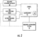
- the system 10 includes a cyber defense response system (CYDRES) 44.
- the cyber defense response system 44 may include a modem or aggregator 42 in communication with the nodes 40a, 40b from each of the buildings 12a, 12b in the system 10.
- the aggregator 42 is, in turn, connected to an external network, such as the Internet, and may allow authorized users to access and control the building systems 30-38.
- the aggregator 42 is integrated with the cyber defense response system 44.
- the cyber defense response system 44 is separate from the aggregator 42, and they communicate through a wired or wireless connection.
- the building automation system 46 is in communication with the cyber defense response system 44.
- the building automation system 46 may be integrated into the cyber defense response system 44, in some examples.
- the cyber defense response system 44 includes a computing device 50, which may include one or more controllers comprising a processor and memory.
- the computing device 50 may include a hardware device for executing software, particularly software stored in memory, such as a cyber attack detection algorithm.
- the computing device 50 may include a custom made or commercially available processor, a central processing unit (CPU), an auxiliary processor among several processors associated with the computing device 50, a semiconductor based microprocessor (in the form of a microchip or chip set), or generally any device for executing software instructions.
- the memory can include any one or combination of volatile memory elements (e.g., random access memory (RAM, such as DRAM, SRAM, SDRAM, VRAM, etc.)) and/or nonvolatile memory elements (e.g., ROM, hard drive, tape, CD-ROM, etc.).
- volatile memory elements e.g., random access memory (RAM, such as DRAM, SRAM, SDRAM, VRAM, etc.)
- nonvolatile memory elements e.g., ROM, hard drive, tape, CD-ROM, etc.
- the memory may incorporate electronic, magnetic, optical, and/or other types of storage media.
- the memory can also have a distributed architecture, where various components are situated remotely from one another, but can be accessed by the processor.
- the software in the memory may include one or more separate programs, each of which includes an ordered listing of executable instructions for implementing logical functions.
- a system component embodied as software may also be construed as a source program, executable program (object code), script, or any other entity comprising a set of instructions to be performed.
- the program is translated via a compiler, assembler, interpreter, or the like, which may or may not be included within the memory.
- the controller can be configured to execute software stored within the memory, to communicate data to and from the memory, and to generally control operations of the computing device 50 pursuant to the software.
- Software in memory, in whole or in part, is read by the processor, perhaps buffered within the processor, and then executed. This software may be used to analyze data from building systems to detect anomalies and determine whether the data indicate that the anomaly is the result of a cyber attack, for example.
- the building automation system 46 and cyber defense response system 44 can then detect malicious activity occurring in one or more of the building systems 30-38 via embedded algorithms and the data from the building systems collected from the nodes 40a, 40b and/or building power characteristics.
- the cyber defense response system 44 compares data from the first node 40a to the second node 40b to determine anomalies.
- the cyber defense response system 44 is connected to the nodes 40a, 40b, and the building automation system 46 wirelessly, such as via BLUETOOTH signaling protocol (IEEE 802.15.1), WiFi (IEEE 802.11), Zigbee (IEEE 802.15.4), Near-Field Communication (NFC), or another signaling protocol, for example.
- BLUETOOTH signaling protocol IEEE 802.15.1
- WiFi IEEE 802.11
- Zigbee IEEE 802.15.4
- NFC Near-Field Communication
- the cyber defense response system 44 may also compare the data with a building behavior database 48 to help detect anomalies.
- the building behavior database 48 may include set values input by an operator for expected building behavior, and/or may store data over time to further improve algorithms.
- the expected power characteristics of the building systems 30-38 may be continuously adapted in the cyber defense response system 44, and the system can account for seasonal variations in expected power characteristics.
- the power characteristics of an air conditioner system will differ from those of a heating system, and the corresponding effect on the building power system will be distinct between a winter season and a summer season.
- an operator can input feedback to the system, such that algorithms for localization and response are improved over time.
- the cyber defense response system 44 is configured to detect anomalies in the system 10 by comparing data from the nodes 40a, 40b, the building behavior database 48, and the network.
- An anomaly in the system 10 may be due to a fault in one of the building systems 30-38, such as a failure of the HVAC system 30a or another building system, or may be a malicious cyber attack. If the anomaly is due to a failure of a building system, then the response might be to alert an operator so that the operator can fix the building system. However, if the anomaly is due to a cyber attack, a different response may be taken.
- the building systems 30-38 behave abnormally resulting in an anomaly in the power characteristics of the power passing through the grid interconnect 22.
- the nodes 40a, 40b and the cyber defense response system 44 are connected to a network, and the cyber defense response system 44 analyzes network behavior, such as traffic and delay, and system response.
- the attack may push a detectable or notable amount of data into the system 10.
- an increase in data traffic detected by the cyber defense response system 44 may be indicative of a cyber attack.
- Comparing data from nodes 40a, 40b across different buildings 12a, 12b helps distinguish system faults from cyber attacks. For example, if a building system, such as an HVAC system 30a breaks down, it will not occur simultaneously across multiple buildings. However, a cyber attack may affect HVAC systems 30a, 30b across multiple buildings simultaneously. When an anomaly is detected across multiple buildings, it is likely a cyber attack.
- the system 10 will respond with a targeted control response.
- the system 10 commands the targeted control response automatically.
- the targeted control response may include automatically switching the building 12a, 12b to a resilient mode of operation based on the localized threat and estimated impact.
- the targeted control response may further include automated isolation and restoration of data and/or activation of resilient control logic.
- the response includes shutting down the system 10 to prevent the attack from infiltrating any further into the system 10 or any of the example building systems.
- the response may be to shut down the cyber defense response system 44, or to disconnect the cyber defense response system 44 and/or nodes 40a, 40b from the network.
- the response includes disconnecting the particular targeted building system 30-38 from the network. This automated response occurs quickly and may help mitigate harm from the attack.
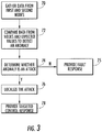
- FIG. 3 summarizes an example method of detecting and responding to anomalies.
- the cyber defense response system 44 gathers data from the nodes 40a, 40b located on different buildings 12a, 12b at 70.
- the cyber defense response system 44 compares the data from the first node 40a with the data from the second node 40b at 72.
- the cyber defense response system 44 may also compare the data from the nodes 40a, 40b with expected values, such as values input by an operator or gathered over time from the building behavior database 48 at 72. When data from one or more of the nodes 40a, 40b deviates from the expected values, an anomaly is detected.
- the cyber defense response system 44 analyzes the data and system to determine whether the detected anomaly is based on or resulting from a cyber attack or a system fault at 74.
- the cyber defense response system 44 analyzes network behavior, such as traffic and delay.
- the cyber defense response system 44 analyzes the variance of the data between the anomaly and the other nodes 40a, 40b and/or from the building behavior database 48. If the anomaly is not considered an attack, the cyber defense response system 44 provides a fault response at 75. In one example, the fault response includes sending an alert to an operator. If the anomaly is determined to be due to an attack, the cyber defense response system 44 localizes the attack at 76 to determine where the cyber attack is coming from and/or which building systems may be affected.
- the localization is based on analyzing data across building systems.
- the cyber defense response system 44 may analyze individual equipment power characteristics, such as the installed HVAC 30a, 30b, the lighting systems 34a, 34b, power consumed by the building systems, and/or building system modes of operation and control data from the building automation system 46.
- the cyber defense response system 44 will respond with a targeted control response at 78.
- the response will include shutting down the system 10 or a portion of the system 10 to prevent the attack from infiltrating any further into the system 10.
- the response will include disconnecting a building system from the network.
- the buildings 12a, 12b, nodes 40a, 40b, and/or building systems 30-38 may be disconnected.
- the building behavior database 48 and/or building automation system 46 may be disconnected from the network.
- the targeted control response is automated.
- the disclosed system and method analyze data from the system to determine whether an anomaly is a malicious cyber attack or a system fault.
- the disclosed system and method further helps mitigate the impact of a successful attack on building devices by providing means to locate, validate, and automatically respond to cyber attacks.
Landscapes
- Engineering & Computer Science (AREA)
- Computer Security & Cryptography (AREA)
- Signal Processing (AREA)
- General Engineering & Computer Science (AREA)
- Computer Networks & Wireless Communication (AREA)
- Computer Hardware Design (AREA)
- Computing Systems (AREA)
- Mechanical Engineering (AREA)
- Chemical & Material Sciences (AREA)
- Combustion & Propulsion (AREA)
- Physics & Mathematics (AREA)
- Theoretical Computer Science (AREA)
- Software Systems (AREA)
- Fuzzy Systems (AREA)
- Mathematical Physics (AREA)
- Health & Medical Sciences (AREA)
- General Health & Medical Sciences (AREA)
- General Physics & Mathematics (AREA)
- Medical Informatics (AREA)
- Data Exchanges In Wide-Area Networks (AREA)
- Computer And Data Communications (AREA)
- Alarm Systems (AREA)
Abstract
Description
- This present disclosure relates generally to a building system, such as a defense and response system for buildings.
- Buildings, such as university buildings, office buildings, residential buildings, and the like, incorporate multiple electrically powered systems. Some or all of these systems are smart systems including Internet, or other network connectivity which facilitates remote control and operation of the building system through computer networks.
- Due to their connections to a computer network, smart building systems can be vulnerable to hacking, malware, or other malicious activity. In addition, smart and non-smart building systems can undergo anomalous behaviors due to malfunctions or other operational irregularities. The anomalous activity can be the result of an individual attempting to attack the building, an individual attempting to use one or more building systems to indirectly attack other building systems, the power grid, or other buildings, or the result of accidental non-malicious activities and malfunctions.
- Viewed from a first aspect, the invention provides a method for a building system comprising: determining a relationship between first data from a first building device and second data from a second building device; determining whether there is an anomaly based on the relationship; and providing an automatic targeted control response if the anomaly indicates an attack.
- In a further embodiment of the above, it is determined whether the anomaly is an attack by detecting at least one of a change in network behavior, a discrepancy between the first data and the second data, and a discrepancy between the first or second data and a predetermined value.
- In a further embodiment of any of the above, the predetermined value is input by an operator.
- In a further embodiment of any of the above, the predetermined value is based on building data that was stored over time.
- In a further embodiment of any of the above, the first and second building devices are connected to a wireless network.
- In a further embodiment of any of the above, a first node is configured to gather the first data from the first building device and a second node is configured to gather the second data from the second building device.
- In a further embodiment of any of the above, the first building device is on a first building and the second building device is on a second building.
- In a further embodiment of any of the above, the attack is localized by determining a source of the anomaly.
- In a further embodiment of any of the above, user feedback of the system is integrated for improved detection of the anomaly and attack localization.
- In a further embodiment of any of the above, the targeted control response comprises disconnecting at least one of the first and second building devices from a network.
- In a further embodiment of any of the above, the targeted control response comprises activating a resilient mode of operation.
- In a further embodiment of any of the above, the building device is a component of an HVAC system.
- In a further embodiment of any of the above, the building device is a component of a lighting system.
- Viewed from a second aspect, the invention provides a building system comprising: a first building system in communication with a first node and a second building system in communication with a second node; and a cyber defense response system in communication with the first node and the second node via a network, the cyber defense response system being configured to command a targeted control response when an anomaly is detected in one of the first node, the second node and the network.
- In a further embodiment of any of the above, the first building system is on a first building and the second building system is on a second building.
- In a further embodiment of any of the above, the cyber defense response system is configured to determine whether the anomaly indicates an attack based on data from the first and second nodes.
- In a further embodiment of any of the above, the cyber defense response system is in communication with a building behavior database and a building automation system.
- In a further embodiment of any of the above, at least one of the cyber defense response system, the building behavior database, and the building automation system is configured to receive input from an operator to improve anomaly detection over time and expedite an attack localization process.
- In a further embodiment of any of the above, the targeted control response comprises disconnecting at least one of the first node, the second node, and the cyber defense response system from the network.
- In a further embodiment of any of the above, the first building system is an HVAC system or a lighting system.
- Certain preferred embodiments will be described by way of example only and with reference to the drawings listed below. The embodiments, examples, and alternatives of the preceding paragraphs, the claims, or the following description and drawings, including any of their various aspects or respective individual features, may be taken independently or in any combination. Features described in connection with one embodiment are applicable to all embodiments, unless such features are incompatible.
-
Figure 1 schematically illustrates a building network. -
Figure 2 schematically illustrates a cyber defense system for a building network. -
Figure 3 schematically illustrates a method of detecting and responding to anomalies. - Smart building systems, or Cyber Physical Systems (CPS) infrastructures, may be susceptible to cyber attacks. Detection and response methods detect conditions that may be a result of such cyber attacks. However, known systems and methods detect anomalies in the system, and do not distinguish between cyber attacks and physical system faults, such as a failure of a particular system in the CPS. The system and method described herein distinguishes between cyber attacks and system faults, and provides an automated response when a cyber attack is detected.
-
Figure 1 schematically illustrates an examplesmart building system 10. Thebuilding system 10 includes afirst building 12a and asecond building 12b. Thebuilding system 10 may include additional buildings, in some examples. Thebuilding 12a may include a heating, ventilation, and cooling (HVAC)system 30a, adoor lock system 32a, alighting system 34a, anelevator system 36 and an electricalvehicle charging system 38, for example. Thesecond building 12b may also include anHVAC system 30b, adoor lock system 32b, alighting system 34b, and/or other systems. The first andsecond buildings buildings - In an example embodiment, each of the
buildings power line 20 viagrid interconnects grid interconnect buildings same power line 20, they may receive power from different power lines in some examples. - Each
building computer network node nodes nodes building grid interconnect nodes nodes - The
system 10 may include abuilding automation system 46, that sends signals to thenodes building automation system 46 is located on thebuilding 12a, but in other examples, thebuilding automation system 46 may be located remotely. Thebuilding automation system 46 may provide signals to all of thebuildings system 10, or to only some of thebuildings building automation system 46 may automate some or all of the example building systems 30-38. For example, thebuilding automation system 46 may be programmed to automatically control the HVAC systems, 30a, 30b. Thebuilding automation system 46 may be connected to an external network, such as the Internet, to allow authorized users to access and control the building systems 30-38 from remote locations and from throughout thebuildings - As shown in
Figure 2 , and with continuing reference toFigure 1 , thesystem 10 includes a cyber defense response system (CYDRES) 44. The cyberdefense response system 44 may include a modem oraggregator 42 in communication with thenodes buildings system 10. Theaggregator 42 is, in turn, connected to an external network, such as the Internet, and may allow authorized users to access and control the building systems 30-38. In some embodiments, theaggregator 42 is integrated with the cyberdefense response system 44. In other embodiments, the cyberdefense response system 44 is separate from theaggregator 42, and they communicate through a wired or wireless connection. Thebuilding automation system 46 is in communication with the cyberdefense response system 44. Thebuilding automation system 46 may be integrated into the cyberdefense response system 44, in some examples. - The cyber
defense response system 44 includes acomputing device 50, which may include one or more controllers comprising a processor and memory. Thecomputing device 50 may include a hardware device for executing software, particularly software stored in memory, such as a cyber attack detection algorithm. Thecomputing device 50 may include a custom made or commercially available processor, a central processing unit (CPU), an auxiliary processor among several processors associated with thecomputing device 50, a semiconductor based microprocessor (in the form of a microchip or chip set), or generally any device for executing software instructions. The memory can include any one or combination of volatile memory elements (e.g., random access memory (RAM, such as DRAM, SRAM, SDRAM, VRAM, etc.)) and/or nonvolatile memory elements (e.g., ROM, hard drive, tape, CD-ROM, etc.). Moreover, the memory may incorporate electronic, magnetic, optical, and/or other types of storage media. Note that the memory can also have a distributed architecture, where various components are situated remotely from one another, but can be accessed by the processor. - The software in the memory may include one or more separate programs, each of which includes an ordered listing of executable instructions for implementing logical functions. A system component embodied as software may also be construed as a source program, executable program (object code), script, or any other entity comprising a set of instructions to be performed. When constructed as a source program, the program is translated via a compiler, assembler, interpreter, or the like, which may or may not be included within the memory.
- The controller can be configured to execute software stored within the memory, to communicate data to and from the memory, and to generally control operations of the
computing device 50 pursuant to the software. Software in memory, in whole or in part, is read by the processor, perhaps buffered within the processor, and then executed. This software may be used to analyze data from building systems to detect anomalies and determine whether the data indicate that the anomaly is the result of a cyber attack, for example. - The
building automation system 46 and cyberdefense response system 44 can then detect malicious activity occurring in one or more of the building systems 30-38 via embedded algorithms and the data from the building systems collected from thenodes defense response system 44 compares data from thefirst node 40a to thesecond node 40b to determine anomalies. In one embodiment, the cyberdefense response system 44 is connected to thenodes building automation system 46 wirelessly, such as via BLUETOOTH signaling protocol (IEEE 802.15.1), WiFi (IEEE 802.11), Zigbee (IEEE 802.15.4), Near-Field Communication (NFC), or another signaling protocol, for example. - The cyber
defense response system 44 may also compare the data with abuilding behavior database 48 to help detect anomalies. Thebuilding behavior database 48 may include set values input by an operator for expected building behavior, and/or may store data over time to further improve algorithms. In an embodiment, the expected power characteristics of the building systems 30-38 may be continuously adapted in the cyberdefense response system 44, and the system can account for seasonal variations in expected power characteristics. By way of example, the power characteristics of an air conditioner system will differ from those of a heating system, and the corresponding effect on the building power system will be distinct between a winter season and a summer season. In some embodiments, an operator can input feedback to the system, such that algorithms for localization and response are improved over time. - The cyber
defense response system 44 is configured to detect anomalies in thesystem 10 by comparing data from thenodes building behavior database 48, and the network. An anomaly in thesystem 10 may be due to a fault in one of the building systems 30-38, such as a failure of theHVAC system 30a or another building system, or may be a malicious cyber attack. If the anomaly is due to a failure of a building system, then the response might be to alert an operator so that the operator can fix the building system. However, if the anomaly is due to a cyber attack, a different response may be taken. - In one example, when a cyber attack or other malicious activity on one or more of the building systems 30-38 is launched using invalid commands, malware, or by changing the control parameters, the building systems 30-38 behave abnormally resulting in an anomaly in the power characteristics of the power passing through the grid interconnect 22. In an example, the
nodes defense response system 44 are connected to a network, and the cyberdefense response system 44 analyzes network behavior, such as traffic and delay, and system response. During a cyber attack, the attack may push a detectable or notable amount of data into thesystem 10. Thus, an increase in data traffic detected by the cyberdefense response system 44 may be indicative of a cyber attack. - Comparing data from
nodes different buildings HVAC system 30a breaks down, it will not occur simultaneously across multiple buildings. However, a cyber attack may affectHVAC systems - If the anomaly detected is likely due to a cyber attack, the
system 10 will respond with a targeted control response. In an embodiment, thesystem 10 commands the targeted control response automatically. The targeted control response may include automatically switching thebuilding system 10 to prevent the attack from infiltrating any further into thesystem 10 or any of the example building systems. The response may be to shut down the cyberdefense response system 44, or to disconnect the cyberdefense response system 44 and/ornodes -
Figure 3 summarizes an example method of detecting and responding to anomalies. The cyberdefense response system 44 gathers data from thenodes different buildings defense response system 44 compares the data from thefirst node 40a with the data from thesecond node 40b at 72. The cyberdefense response system 44 may also compare the data from thenodes building behavior database 48 at 72. When data from one or more of thenodes - The cyber
defense response system 44 analyzes the data and system to determine whether the detected anomaly is based on or resulting from a cyber attack or a system fault at 74. In one example, the cyberdefense response system 44 analyzes network behavior, such as traffic and delay. In another example, the cyberdefense response system 44 analyzes the variance of the data between the anomaly and theother nodes building behavior database 48. If the anomaly is not considered an attack, the cyberdefense response system 44 provides a fault response at 75. In one example, the fault response includes sending an alert to an operator. If the anomaly is determined to be due to an attack, the cyberdefense response system 44 localizes the attack at 76 to determine where the cyber attack is coming from and/or which building systems may be affected. The localization is based on analyzing data across building systems. For example, the cyberdefense response system 44 may analyze individual equipment power characteristics, such as the installedHVAC lighting systems building automation system 46. - When a cyber attack is detected, the cyber
defense response system 44 will respond with a targeted control response at 78. In one example, the response will include shutting down thesystem 10 or a portion of thesystem 10 to prevent the attack from infiltrating any further into thesystem 10. In another example, the response will include disconnecting a building system from the network. For example, at least one of thebuildings nodes building behavior database 48 and/orbuilding automation system 46 may be disconnected from the network. In an embodiment, the targeted control response is automated. - The disclosed system and method analyze data from the system to determine whether an anomaly is a malicious cyber attack or a system fault. The disclosed system and method further helps mitigate the impact of a successful attack on building devices by providing means to locate, validate, and automatically respond to cyber attacks.
- It is further understood that any of the above described concepts can be used alone or in combination with any or all of the other above described concepts. Although an embodiment of this invention has been disclosed, a worker of ordinary skill in this art would recognize that certain modifications would come within the scope of this invention, which is defined by the claims. For that reason, the following claims should be studied to determine the true scope and content of this invention.
Claims (15)
- A method for a building system, comprising:determining a relationship between first data from a first building device and second data from a second building device;determining whether there is an anomaly based on the relationship; andproviding an automatic targeted control response if the anomaly indicates an attack.
- The method of claim 1, comprising: determining whether the anomaly is an attack by detecting at least one of a change in network behavior, a discrepancy between the first data and the second data, and a discrepancy between the first or second data and a predetermined value.
- The method of claim 2, wherein the predetermined value is input by an operator.
- The method of claim 2, wherein the predetermined value is based on building data that was stored over time.
- The method of any preceding claim, wherein the first and second building devices are connected to a wireless network.
- The method of any preceding claim, wherein a first node is configured to gather the first data from the first building device and a second node is configured to gather the second data from the second building device.
- The method of any preceding claim, wherein the first building device is on a first building and the second building device is on a second building.
- The method of any preceding claim, comprising: localizing the attack by determining a source of the anomaly.
- The method of claim 8, comprising: integrating user feedback of the system for improved detection of the anomaly and attack localization.
- The method of any preceding claim, wherein the targeted control response comprises disconnecting at least one of the first and second building devices from a network.
- The method of any preceding claim, wherein the targeted control response comprises activating a resilient mode of operation.
- The method of any preceding claim, wherein the building device is a component of an HVAC system.
- The method of any preceding claim, wherein the building device is a component of a lighting system.
- A building system, comprising:a first building system in communication with a first node;a second building system in communication with a second node; anda cyber defense response system in communication with the first node and the second node via a network, the cyber defense response system configured to command a targeted control response when an anomaly is detected in one of the first node, the second node and the network.
- The building system of claim 14, being configured to operate in accordance with the method of any of claims 1 to 13.
Applications Claiming Priority (1)
| Application Number | Priority Date | Filing Date | Title |
|---|---|---|---|
| US201962801348P | 2019-02-05 | 2019-02-05 |
Publications (2)
| Publication Number | Publication Date |
|---|---|
| EP3693882A1 true EP3693882A1 (en) | 2020-08-12 |
| EP3693882B1 EP3693882B1 (en) | 2025-09-03 |
Family
ID=69500607
Family Applications (1)
| Application Number | Title | Priority Date | Filing Date |
|---|---|---|---|
| EP20155648.7A Active EP3693882B1 (en) | 2019-02-05 | 2020-02-05 | Cyber defense and response system for buildings |
Country Status (3)
| Country | Link |
|---|---|
| US (1) | US20200252420A1 (en) |
| EP (1) | EP3693882B1 (en) |
| CN (1) | CN111526117A (en) |
Citations (5)
| Publication number | Priority date | Publication date | Assignee | Title |
|---|---|---|---|---|
| US20130174256A1 (en) * | 2011-12-29 | 2013-07-04 | Architecture Technology Corporation | Network defense system and framework for detecting and geolocating botnet cyber attacks |
| US20160366170A1 (en) * | 2015-02-09 | 2016-12-15 | Utilidata, Inc. | Systems and methods of detecting utility grid intrusions |
| US20170184416A1 (en) * | 2015-12-26 | 2017-06-29 | Tobias M. Kohlenberg | Technologies for managing sensor anomalies |
| US20180069879A1 (en) * | 2016-09-05 | 2018-03-08 | Cisco Technology, Inc. | Smart home security system |
| US20180191676A1 (en) * | 2016-12-30 | 2018-07-05 | Fortinet, Inc. | Management of internet of things (iot) by security fabric |
Family Cites Families (7)
| Publication number | Priority date | Publication date | Assignee | Title |
|---|---|---|---|---|
| JP6365112B2 (en) * | 2014-08-20 | 2018-08-01 | 株式会社デンソー | Control device for in-vehicle motor |
| US10498752B2 (en) * | 2016-03-28 | 2019-12-03 | Cisco Technology, Inc. | Adaptive capture of packet traces based on user feedback learning |
| CN106657019A (en) * | 2016-11-24 | 2017-05-10 | 华为技术有限公司 | Network security protection method and device |
| EP3343968B1 (en) * | 2016-12-30 | 2021-08-11 | u-blox AG | Monitoring apparatus, device monitoring system and method of monitoring a plurality of networked devices |
| US10623416B2 (en) * | 2018-01-31 | 2020-04-14 | International Business Machines Corporation | Torrent attack detection |
| US10789507B2 (en) * | 2018-03-30 | 2020-09-29 | Walmart Apollo, Llc | Relative density-based clustering and anomaly detection system |
| US10826932B2 (en) * | 2018-08-22 | 2020-11-03 | General Electric Company | Situation awareness and dynamic ensemble forecasting of abnormal behavior in cyber-physical system |
-
2020
- 2020-01-23 US US16/750,886 patent/US20200252420A1/en not_active Abandoned
- 2020-02-05 CN CN202010080482.1A patent/CN111526117A/en active Pending
- 2020-02-05 EP EP20155648.7A patent/EP3693882B1/en active Active
Patent Citations (5)
| Publication number | Priority date | Publication date | Assignee | Title |
|---|---|---|---|---|
| US20130174256A1 (en) * | 2011-12-29 | 2013-07-04 | Architecture Technology Corporation | Network defense system and framework for detecting and geolocating botnet cyber attacks |
| US20160366170A1 (en) * | 2015-02-09 | 2016-12-15 | Utilidata, Inc. | Systems and methods of detecting utility grid intrusions |
| US20170184416A1 (en) * | 2015-12-26 | 2017-06-29 | Tobias M. Kohlenberg | Technologies for managing sensor anomalies |
| US20180069879A1 (en) * | 2016-09-05 | 2018-03-08 | Cisco Technology, Inc. | Smart home security system |
| US20180191676A1 (en) * | 2016-12-30 | 2018-07-05 | Fortinet, Inc. | Management of internet of things (iot) by security fabric |
Also Published As
| Publication number | Publication date |
|---|---|
| CN111526117A (en) | 2020-08-11 |
| EP3693882B1 (en) | 2025-09-03 |
| US20200252420A1 (en) | 2020-08-06 |
Similar Documents
| Publication | Publication Date | Title |
|---|---|---|
| JP5926491B2 (en) | Method for security maintenance in a network and computer readable medium having computer readable instructions of a computer program causing a processor to perform the method for security maintenance | |
| US9471770B2 (en) | Method and control unit for recognizing manipulations on a vehicle network | |
| US20190013958A1 (en) | Network security analysis for smart appliances | |
| US20190149563A1 (en) | Network Security Analysis for Smart Appliances | |
| Sheikh et al. | Cyber attack and fault identification of hvac system in building management systems | |
| US10088883B2 (en) | Executing restricted commands on an uninterrupted power supply | |
| US9756075B1 (en) | Dynamic hiding of deception mechanism | |
| US20170329783A1 (en) | Systems and methods for identifying similar hosts | |
| US20210155270A1 (en) | Information Processing Device and Abnormality Handling Method | |
| KR101966345B1 (en) | Method and System for detecting bypass hacking attacks based on the CAN protocol | |
| EP3182669B1 (en) | Integrated industrial system and control method thereof | |
| US20170024983A1 (en) | System and method for tamper detection on distributed utility infrastructure | |
| EP2169484A1 (en) | Control of concept zones | |
| WO2020051018A1 (en) | System and method for detecting malicious activities and anomalies in building systems | |
| US10777376B2 (en) | Method and system for hardware tamper detection and mitigation for solid state circuit breaker and its controller | |
| US11621972B2 (en) | System and method for protection of an ICS network by an HMI server therein | |
| EP3693882B1 (en) | Cyber defense and response system for buildings | |
| KR101969815B1 (en) | IoT Gateway | |
| US10503229B2 (en) | Uninterruptible power supply communication | |
| CN115150197B (en) | Method and system for preventing command attack of UPS (uninterrupted Power supply) air conditioning equipment | |
| CN113126577B (en) | Security network for safety PLCs in industrial plants | |
| Negi et al. | Intrusion detection & prevention in programmable logic controllers: A model-driven approach | |
| KR101343693B1 (en) | Network security system and method for process thereof | |
| WO2018107542A1 (en) | Intelligent device and household appliance | |
| Hattori et al. | Function estimation of multiple IoT devices by communication traffic analysis |
Legal Events
| Date | Code | Title | Description |
|---|---|---|---|
| PUAI | Public reference made under article 153(3) epc to a published international application that has entered the european phase |
Free format text: ORIGINAL CODE: 0009012 |
|
| STAA | Information on the status of an ep patent application or granted ep patent |
Free format text: STATUS: THE APPLICATION HAS BEEN PUBLISHED |
|
| AK | Designated contracting states |
Kind code of ref document: A1 Designated state(s): AL AT BE BG CH CY CZ DE DK EE ES FI FR GB GR HR HU IE IS IT LI LT LU LV MC MK MT NL NO PL PT RO RS SE SI SK SM TR |
|
| AX | Request for extension of the european patent |
Extension state: BA ME |
|
| STAA | Information on the status of an ep patent application or granted ep patent |
Free format text: STATUS: REQUEST FOR EXAMINATION WAS MADE |
|
| 17P | Request for examination filed |
Effective date: 20210212 |
|
| RBV | Designated contracting states (corrected) |
Designated state(s): AL AT BE BG CH CY CZ DE DK EE ES FI FR GB GR HR HU IE IS IT LI LT LU LV MC MK MT NL NO PL PT RO RS SE SI SK SM TR |
|
| STAA | Information on the status of an ep patent application or granted ep patent |
Free format text: STATUS: EXAMINATION IS IN PROGRESS |
|
| 17Q | First examination report despatched |
Effective date: 20220330 |
|
| REG | Reference to a national code |
Ref country code: DE Ref legal event code: R079 Free format text: PREVIOUS MAIN CLASS: G06F0021560000 Ipc: H04L0009400000 Ref country code: DE Ref legal event code: R079 Ref document number: 602020057833 Country of ref document: DE Free format text: PREVIOUS MAIN CLASS: G06F0021560000 Ipc: H04L0009400000 |
|
| GRAP | Despatch of communication of intention to grant a patent |
Free format text: ORIGINAL CODE: EPIDOSNIGR1 |
|
| STAA | Information on the status of an ep patent application or granted ep patent |
Free format text: STATUS: GRANT OF PATENT IS INTENDED |
|
| RIC1 | Information provided on ipc code assigned before grant |
Ipc: H04W 12/122 20210101ALI20250226BHEP Ipc: H04W 12/08 20090101ALI20250226BHEP Ipc: G06F 21/57 20130101ALI20250226BHEP Ipc: H04L 9/40 20220101AFI20250226BHEP |
|
| INTG | Intention to grant announced |
Effective date: 20250402 |
|
| GRAS | Grant fee paid |
Free format text: ORIGINAL CODE: EPIDOSNIGR3 |
|
| GRAA | (expected) grant |
Free format text: ORIGINAL CODE: 0009210 |
|
| STAA | Information on the status of an ep patent application or granted ep patent |
Free format text: STATUS: THE PATENT HAS BEEN GRANTED |
|
| AK | Designated contracting states |
Kind code of ref document: B1 Designated state(s): AL AT BE BG CH CY CZ DE DK EE ES FI FR GB GR HR HU IE IS IT LI LT LU LV MC MK MT NL NO PL PT RO RS SE SI SK SM TR |
|
| REG | Reference to a national code |
Ref country code: CH Ref legal event code: EP |
|
| REG | Reference to a national code |
Ref country code: DE Ref legal event code: R096 Ref document number: 602020057833 Country of ref document: DE |
|
| REG | Reference to a national code |
Ref country code: IE Ref legal event code: FG4D |
|
| REG | Reference to a national code |
Ref country code: NL Ref legal event code: MP Effective date: 20250903 |
|
| PG25 | Lapsed in a contracting state [announced via postgrant information from national office to epo] |
Ref country code: NO Free format text: LAPSE BECAUSE OF FAILURE TO SUBMIT A TRANSLATION OF THE DESCRIPTION OR TO PAY THE FEE WITHIN THE PRESCRIBED TIME-LIMIT Effective date: 20251203 |
|
| REG | Reference to a national code |
Ref country code: LT Ref legal event code: MG9D |
|
| PG25 | Lapsed in a contracting state [announced via postgrant information from national office to epo] |
Ref country code: FI Free format text: LAPSE BECAUSE OF FAILURE TO SUBMIT A TRANSLATION OF THE DESCRIPTION OR TO PAY THE FEE WITHIN THE PRESCRIBED TIME-LIMIT Effective date: 20250903 |
|
| PG25 | Lapsed in a contracting state [announced via postgrant information from national office to epo] |
Ref country code: HR Free format text: LAPSE BECAUSE OF FAILURE TO SUBMIT A TRANSLATION OF THE DESCRIPTION OR TO PAY THE FEE WITHIN THE PRESCRIBED TIME-LIMIT Effective date: 20250903 |
|
| PG25 | Lapsed in a contracting state [announced via postgrant information from national office to epo] |
Ref country code: GR Free format text: LAPSE BECAUSE OF FAILURE TO SUBMIT A TRANSLATION OF THE DESCRIPTION OR TO PAY THE FEE WITHIN THE PRESCRIBED TIME-LIMIT Effective date: 20251204 |
|
| PG25 | Lapsed in a contracting state [announced via postgrant information from national office to epo] |
Ref country code: SE Free format text: LAPSE BECAUSE OF FAILURE TO SUBMIT A TRANSLATION OF THE DESCRIPTION OR TO PAY THE FEE WITHIN THE PRESCRIBED TIME-LIMIT Effective date: 20250903 |
|
| PG25 | Lapsed in a contracting state [announced via postgrant information from national office to epo] |
Ref country code: LV Free format text: LAPSE BECAUSE OF FAILURE TO SUBMIT A TRANSLATION OF THE DESCRIPTION OR TO PAY THE FEE WITHIN THE PRESCRIBED TIME-LIMIT Effective date: 20250903 |
|
| PG25 | Lapsed in a contracting state [announced via postgrant information from national office to epo] |
Ref country code: BG Free format text: LAPSE BECAUSE OF FAILURE TO SUBMIT A TRANSLATION OF THE DESCRIPTION OR TO PAY THE FEE WITHIN THE PRESCRIBED TIME-LIMIT Effective date: 20250903 Ref country code: PL Free format text: LAPSE BECAUSE OF FAILURE TO SUBMIT A TRANSLATION OF THE DESCRIPTION OR TO PAY THE FEE WITHIN THE PRESCRIBED TIME-LIMIT Effective date: 20250903 |
|
| PG25 | Lapsed in a contracting state [announced via postgrant information from national office to epo] |
Ref country code: RS Free format text: LAPSE BECAUSE OF FAILURE TO SUBMIT A TRANSLATION OF THE DESCRIPTION OR TO PAY THE FEE WITHIN THE PRESCRIBED TIME-LIMIT Effective date: 20251203 |
|
| PG25 | Lapsed in a contracting state [announced via postgrant information from national office to epo] |
Ref country code: ES Free format text: LAPSE BECAUSE OF FAILURE TO SUBMIT A TRANSLATION OF THE DESCRIPTION OR TO PAY THE FEE WITHIN THE PRESCRIBED TIME-LIMIT Effective date: 20250903 |
|
| REG | Reference to a national code |
Ref country code: AT Ref legal event code: MK05 Ref document number: 1834526 Country of ref document: AT Kind code of ref document: T Effective date: 20250903 |
|
| PG25 | Lapsed in a contracting state [announced via postgrant information from national office to epo] |
Ref country code: NL Free format text: LAPSE BECAUSE OF FAILURE TO SUBMIT A TRANSLATION OF THE DESCRIPTION OR TO PAY THE FEE WITHIN THE PRESCRIBED TIME-LIMIT Effective date: 20250903 |
|
| PG25 | Lapsed in a contracting state [announced via postgrant information from national office to epo] |
Ref country code: SM Free format text: LAPSE BECAUSE OF FAILURE TO SUBMIT A TRANSLATION OF THE DESCRIPTION OR TO PAY THE FEE WITHIN THE PRESCRIBED TIME-LIMIT Effective date: 20250903 |
|
| PGFP | Annual fee paid to national office [announced via postgrant information from national office to epo] |
Ref country code: DE Payment date: 20260121 Year of fee payment: 7 |
|
| PG25 | Lapsed in a contracting state [announced via postgrant information from national office to epo] |
Ref country code: AT Free format text: LAPSE BECAUSE OF FAILURE TO SUBMIT A TRANSLATION OF THE DESCRIPTION OR TO PAY THE FEE WITHIN THE PRESCRIBED TIME-LIMIT Effective date: 20250903 |
|
| PG25 | Lapsed in a contracting state [announced via postgrant information from national office to epo] |
Ref country code: IT Free format text: LAPSE BECAUSE OF FAILURE TO SUBMIT A TRANSLATION OF THE DESCRIPTION OR TO PAY THE FEE WITHIN THE PRESCRIBED TIME-LIMIT Effective date: 20250903 |
|
| PG25 | Lapsed in a contracting state [announced via postgrant information from national office to epo] |
Ref country code: IS Free format text: LAPSE BECAUSE OF FAILURE TO SUBMIT A TRANSLATION OF THE DESCRIPTION OR TO PAY THE FEE WITHIN THE PRESCRIBED TIME-LIMIT Effective date: 20260103 |
|
| PGFP | Annual fee paid to national office [announced via postgrant information from national office to epo] |
Ref country code: FR Payment date: 20260121 Year of fee payment: 7 |
|
| PG25 | Lapsed in a contracting state [announced via postgrant information from national office to epo] |
Ref country code: PT Free format text: LAPSE BECAUSE OF FAILURE TO SUBMIT A TRANSLATION OF THE DESCRIPTION OR TO PAY THE FEE WITHIN THE PRESCRIBED TIME-LIMIT Effective date: 20260105 Ref country code: CZ Free format text: LAPSE BECAUSE OF FAILURE TO SUBMIT A TRANSLATION OF THE DESCRIPTION OR TO PAY THE FEE WITHIN THE PRESCRIBED TIME-LIMIT Effective date: 20250903 |
|
| PG25 | Lapsed in a contracting state [announced via postgrant information from national office to epo] |
Ref country code: EE Free format text: LAPSE BECAUSE OF FAILURE TO SUBMIT A TRANSLATION OF THE DESCRIPTION OR TO PAY THE FEE WITHIN THE PRESCRIBED TIME-LIMIT Effective date: 20250903 Ref country code: SK Free format text: LAPSE BECAUSE OF FAILURE TO SUBMIT A TRANSLATION OF THE DESCRIPTION OR TO PAY THE FEE WITHIN THE PRESCRIBED TIME-LIMIT Effective date: 20250903 |