EP3693802A1 - Fixing device and image forming apparatus incorporating same - Google Patents
Fixing device and image forming apparatus incorporating same Download PDFInfo
- Publication number
- EP3693802A1 EP3693802A1 EP20154150.5A EP20154150A EP3693802A1 EP 3693802 A1 EP3693802 A1 EP 3693802A1 EP 20154150 A EP20154150 A EP 20154150A EP 3693802 A1 EP3693802 A1 EP 3693802A1
- Authority
- EP
- European Patent Office
- Prior art keywords
- heat
- shield
- fixing
- nip formation
- fixing device
- Prior art date
- Legal status (The legal status is an assumption and is not a legal conclusion. Google has not performed a legal analysis and makes no representation as to the accuracy of the status listed.)
- Withdrawn
Links
- 230000015572 biosynthetic process Effects 0.000 claims abstract description 106
- 238000003825 pressing Methods 0.000 claims abstract description 23
- 239000011248 coating agent Substances 0.000 claims description 27
- 238000010521 absorption reaction Methods 0.000 claims description 7
- 230000020169 heat generation Effects 0.000 claims description 4
- 238000012546 transfer Methods 0.000 description 36
- 229910052736 halogen Inorganic materials 0.000 description 34
- 150000002367 halogens Chemical class 0.000 description 34
- 238000010438 heat treatment Methods 0.000 description 13
- 238000000576 coating method Methods 0.000 description 6
- 238000013461 design Methods 0.000 description 5
- 239000000463 material Substances 0.000 description 5
- 230000000903 blocking effect Effects 0.000 description 3
- 238000010586 diagram Methods 0.000 description 3
- 229920001971 elastomer Polymers 0.000 description 3
- 229910052751 metal Inorganic materials 0.000 description 3
- 239000002184 metal Substances 0.000 description 3
- 238000012986 modification Methods 0.000 description 3
- 230000004048 modification Effects 0.000 description 3
- 238000013021 overheating Methods 0.000 description 3
- 229920001343 polytetrafluoroethylene Polymers 0.000 description 3
- 239000004810 polytetrafluoroethylene Substances 0.000 description 3
- 229920002379 silicone rubber Polymers 0.000 description 3
- 239000004945 silicone rubber Substances 0.000 description 3
- 238000011144 upstream manufacturing Methods 0.000 description 3
- RYGMFSIKBFXOCR-UHFFFAOYSA-N Copper Chemical compound [Cu] RYGMFSIKBFXOCR-UHFFFAOYSA-N 0.000 description 2
- XEEYBQQBJWHFJM-UHFFFAOYSA-N Iron Chemical compound [Fe] XEEYBQQBJWHFJM-UHFFFAOYSA-N 0.000 description 2
- PXHVJJICTQNCMI-UHFFFAOYSA-N Nickel Chemical compound [Ni] PXHVJJICTQNCMI-UHFFFAOYSA-N 0.000 description 2
- 229910000831 Steel Inorganic materials 0.000 description 2
- 238000004140 cleaning Methods 0.000 description 2
- 238000002845 discoloration Methods 0.000 description 2
- 229920001973 fluoroelastomer Polymers 0.000 description 2
- 239000006260 foam Substances 0.000 description 2
- 230000002093 peripheral effect Effects 0.000 description 2
- -1 polytetrafluoroethylene Polymers 0.000 description 2
- 239000007787 solid Substances 0.000 description 2
- 229910001220 stainless steel Inorganic materials 0.000 description 2
- 239000010935 stainless steel Substances 0.000 description 2
- 239000010959 steel Substances 0.000 description 2
- YCKRFDGAMUMZLT-UHFFFAOYSA-N Fluorine atom Chemical compound [F] YCKRFDGAMUMZLT-UHFFFAOYSA-N 0.000 description 1
- 239000004642 Polyimide Substances 0.000 description 1
- 238000005299 abrasion Methods 0.000 description 1
- 229910052782 aluminium Inorganic materials 0.000 description 1
- XAGFODPZIPBFFR-UHFFFAOYSA-N aluminium Chemical compound [Al] XAGFODPZIPBFFR-UHFFFAOYSA-N 0.000 description 1
- 238000005452 bending Methods 0.000 description 1
- 238000010276 construction Methods 0.000 description 1
- 229920001577 copolymer Polymers 0.000 description 1
- 229910052802 copper Inorganic materials 0.000 description 1
- 239000010949 copper Substances 0.000 description 1
- 239000011889 copper foil Substances 0.000 description 1
- 230000001419 dependent effect Effects 0.000 description 1
- 229910052731 fluorine Inorganic materials 0.000 description 1
- 239000011737 fluorine Substances 0.000 description 1
- 229920001821 foam rubber Polymers 0.000 description 1
- 239000004519 grease Substances 0.000 description 1
- 238000005338 heat storage Methods 0.000 description 1
- 238000009413 insulation Methods 0.000 description 1
- 229910052742 iron Inorganic materials 0.000 description 1
- 239000000314 lubricant Substances 0.000 description 1
- 238000000034 method Methods 0.000 description 1
- 229910052759 nickel Inorganic materials 0.000 description 1
- 239000002985 plastic film Substances 0.000 description 1
- 229920006255 plastic film Polymers 0.000 description 1
- 229920001721 polyimide Polymers 0.000 description 1
- 238000007639 printing Methods 0.000 description 1
- 239000011347 resin Substances 0.000 description 1
- 229920005989 resin Polymers 0.000 description 1
- 238000000926 separation method Methods 0.000 description 1
- 238000004904 shortening Methods 0.000 description 1
Images




Classifications
-
- G—PHYSICS
- G03—PHOTOGRAPHY; CINEMATOGRAPHY; ANALOGOUS TECHNIQUES USING WAVES OTHER THAN OPTICAL WAVES; ELECTROGRAPHY; HOLOGRAPHY
- G03G—ELECTROGRAPHY; ELECTROPHOTOGRAPHY; MAGNETOGRAPHY
- G03G15/00—Apparatus for electrographic processes using a charge pattern
- G03G15/20—Apparatus for electrographic processes using a charge pattern for fixing, e.g. by using heat
- G03G15/2003—Apparatus for electrographic processes using a charge pattern for fixing, e.g. by using heat using heat
- G03G15/2014—Apparatus for electrographic processes using a charge pattern for fixing, e.g. by using heat using heat using contact heat
- G03G15/2053—Structural details of heat elements, e.g. structure of roller or belt, eddy current, induction heating
-
- G—PHYSICS
- G03—PHOTOGRAPHY; CINEMATOGRAPHY; ANALOGOUS TECHNIQUES USING WAVES OTHER THAN OPTICAL WAVES; ELECTROGRAPHY; HOLOGRAPHY
- G03G—ELECTROGRAPHY; ELECTROPHOTOGRAPHY; MAGNETOGRAPHY
- G03G2215/00—Apparatus for electrophotographic processes
- G03G2215/20—Details of the fixing device or porcess
- G03G2215/2003—Structural features of the fixing device
- G03G2215/2016—Heating belt
- G03G2215/2035—Heating belt the fixing nip having a stationary belt support member opposing a pressure member
Definitions
- Embodiments of the present disclosure generally relate to a fixing device and an image forming apparatus incorporating the fixing device.
- An image forming apparatus such as a copier, a printer, a facsimile machine, and a multi-functional apparatus including at least two functions of the copier, printer, facsimile machine includes a fixing device to convey a recording medium such as a sheet on which an unfixed image is formed to a fixing nip formed between a fixing member and a pressing member in the fixing device, heat the recording medium, and fix the unfixed image onto the recording medium.
- the fixing device includes a fixing belt as a cylindrical fixing member and a heat generator such as a halogen heater disposed inside a loop of the fixing belt to heat the fixing belt.
- the heat generator heats the fixing belt via a nip formation member disposed inside the loop of the fixing belt and raises a temperature of the fixing belt to a fixing temperature that enables fixing an image onto a recording medium.
- the heat generator quickly heats the fixing belt to make the high speed fixing device.
- JP-2016-35601-A discloses the fixing device including two halogen lamps arranged inside a loop of a fixing film and along a direction perpendicular to a sheet conveyance direction. Including two halogen lamps in the fixing device can increase an amount of heat applied to the fixing film and quickly raise the temperature of the fixing film to the fixing temperature.
- the fixing device including a plurality of heat generators inside the loop of the fixing member as described in JP-2016-35601-A has a disadvantage that one heat generator heats the other heat generator, and the temperature of the other heat generator exceeds a heatproof temperature of material of the other heat generator.
- an object of the present disclosure is to prevent a plurality of heat generators from heating each other.
- the fixing device includes a fixing member in a cylindrical form, a pressing member configured to press an outer surface of the fixing member, a nip formation member disposed inside a loop of the fixing member, a plurality of heat generators disposed inside the loop of the fixing member and configured to heat the fixing member, and a shield disposed inside the loop of the fixing member and configured to block heat from the heat generators.
- the nip formation member is configured to be pressed by the pressing member via the fixing member to form a fixing nip.
- the plurality of heat generators includes one heat generator disposed close to the nip formation member and the other heat generator disposed farther from the nip formation member than the one heat generator in a direction that is perpendicular to a recording medium conveyance direction and is not a width direction of the fixing member.
- the shield has a part disposed between the one heat generator and the other heat generator in a cross section that intersects the width direction of the fixing member.
- providing the shield between the one heat generator disposed near the nip formation member and the other heat generator disposed apart from the nip formation member can prevent the heat generators from heating each other.
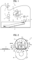
- FIG. 1 is a schematic diagram illustrating a configuration of an image forming apparatus according to an embodiment of the present disclosure. Referring to FIG. 1 , a configuration and operation of the image forming apparatus according to the present embodiment are described below.
- An image forming apparatus 1 illustrated in FIG. 1 is a monochrome electrophotographic laser printer.
- the image forming apparatus 1 may be a printer, a copier, a facsimile machine or a multifunction peripheral (MFP) having at least two of copying, printing, scanning, facsimile, and plotter functions.
- the image forming apparatus 1 is not limited to a monochrome image forming apparatus and may be a color image forming apparatus.
- the image forming apparatus 1 includes an image forming device 2 to form an image, a recording medium feeding device 3 to feed a sheet P as a recording medium to the image forming device 2, a transfer device 4 to transfer the image onto the fed sheet P, a fixing device 5 to fix the image transferred onto the sheet P, and a sheet ejection device 6 to eject the sheet P with the fixed image to an outside of the image forming apparatus 1.
- the image forming device 2 includes a drum-shaped photoconductor 7, a charging roller 8 as a charging device to charge a surface of the photoconductor 7, an exposure device 9 as a latent image forming device that exposes the surface of the photoconductor 7 to form an electrostatic latent image on the photoconductor 7, a developing roller 10 as a developing device that supplies toner as a developer to the surface of the photoconductor 7 to visualize the electrostatic latent image, and a cleaning blade 11 as a cleaner to clean the surface of the photoconductor 7.
- the photoconductor 7 starts to rotate, and the charging roller 8 uniformly charges the surface of the photoconductor 7 to a high potential.
- the exposure device 9 exposes the surface of the photoconductor 7. Potential of an exposed surface drops, and the electrostatic latent image is formed on the photoconductor 7.
- the developing roller 10 supplies toner to the electrostatic latent image, thereby developing the latent image into the toner image on the photoconductor 7.
- the toner image formed on the photoconductor 7 is transferred onto the sheet P in a transfer nip between the photoconductor 7 and a transfer roller 15 disposed in the transfer device 4.
- the sheet P is fed from the recording medium feeding device 3.
- a sheet feeding roller 13 feeds the sheet P from a sheet tray 12 to a feeding path one by one.
- a timing roller pair 14 sends out the sheet P fed from the sheet tray 12 to a transfer nip, timed to coincide with the toner image on the photoconductor 7.
- the toner image on the photoconductor 7 is transferred onto the sheet P at the transfer nip.
- the cleaning blade 11 removes residual toner on the photoconductor 7.
- the sheet P bearing the toner image is conveyed to the fixing device 5.
- the fixing device 5 heat and pressure when the sheet P passes through between a fixing belt 22 and a pressure roller 23 fixes the toner image onto the sheet P.
- the sheet P is conveyed to the sheet ejection device 6, and an ejection roller pair 16 ejects the sheet P outside the image forming apparatus 1, and a series of print operations are completed.
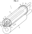
- FIG. 2 is a vertical cross-sectional view of the fixing device 5 viewed from a lateral side of the fixing device 5
- FIG. 3 is a perspective view of the fixing device 5 with the vertical cross-sectional view of the fixing device
- FIG. 4 is a vertical cross-sectional view of the fixing device 5 viewed from a front side of the fixing device 5.
- FIG. 5 is a perspective view of a belt holder 35 to support the fixing belt 22
- FIG. 6 is a perspective view of a variation of the belt holder 35.
- the fixing device 5 includes the fixing belt 22 as a fixing member, the pressure roller 23 as a pressing member, a halogen heaters 31a and 31b as heat generators, a nip formation member 32, a stay 33 as a contact member, and a heat shield 34.
- the halogen heaters 31a and 31b, the nip formation member 32, the stay 33, and the heat shield 34 are members extending along a width direction of the fixing belt 22 that is a direction perpendicular to a surface of a sheet of FIG. 2 and a lateral direction in FIG. 4 .
- the width direction of the fixing belt 22 is simply referred to as the width direction.
- the fixing belt 22 is a cylindrical fixing member to fix an unfixed image T to the sheet P and is disposed on the side of the sheet P on which the unfixed image T is held.
- the fixing belt 22 in the present embodiment is an endless belt or film, including a base layer formed on an inner side of the fixing belt 22 and made of a metal such as nickel and stainless steel (SUS) or a resin such as polyimide, and a release layer formed on the outer side of the fixing belt 22 and made of tetrafluoroethylene-perfluoroalkylvinylether copolymer (PFA), polytetrafluoroethylene (PTFE), or the like.
- SUS nickel and stainless steel
- PFA tetrafluoroethylene-perfluoroalkylvinylether copolymer
- PTFE polytetrafluoroethylene
- an elastic layer made of rubber such as silicone rubber, silicone rubber foam, and fluoro rubber may be interposed between the base layer and the release layer.
- the fixing belt 22 and the pressure roller 23 press the unfixed toner image against the sheet P to fix the toner image onto the sheet P
- the elastic layer having a thickness of about 100 micrometers elastically deforms to absorb slight surface asperities of the fixing belt 22, preventing variation in gloss of the toner image on the sheet P.
- the fixing belt 22 is thin and has a small loop diameter to decrease the thermal capacity of the fixing belt 22.
- the base layer of the fixing belt 22 has a thickness of from 20 ⁇ m to 50 ⁇ m and the release layer has a thickness of from 10 ⁇ m to 50 ⁇ m.
- the fixing belt 22 has a total thickness not greater than 1 mm.
- the thickness of the elastic layer may be set to 100 to 300 ⁇ m.
- the fixing belt 22 may have the total thickness not greater than 0.20 mm and preferably not greater than 0.16 mm.
- the fixing belt 22 may have a loop diameter from 20 to 40 mm and preferably 30 mm or less.
- the pressure roller 23 is an opposed member disposed opposite an outer circumferential surface of the fixing belt 22.
- the pressure roller 23 includes a cored bar; an elastic layer coating the cored bar and being made of silicone rubber foam, fluoro rubber, or the like; and a release layer coating the elastic layer and being made of PFA, PTFE, or the like.
- the pressure roller 23 is a solid roller.
- the pressure roller 23 may be a hollow roller.
- a heater such as a halogen heater may be disposed inside the pressure roller 23.
- the elastic layer of the pressure roller 23 may be made of solid rubber.
- the elastic layer of the pressure roller 23 is preferably made of sponge rubber to enhance thermal insulation of the pressure roller 23.
- Such a configuration reduces heat conduction from the fixing belt 22 to the pressure roller 23 and improves heating efficiency of the fixing belt 22.
- a driver disposed inside the image forming apparatus 1 drives and rotates the pressure roller 23 in a direction indicated by arrow A in FIG. 2 .
- the rotation of the pressure roller 23 drives the fixing belt 22 to rotate in a direction indicated by arrow B in FIG. 2 (hereinafter, belt rotation direction B) due to frictional force therebetween.
- the pressure roller 23 and the fixing belt 22 are configured to be able to contact and separate from each other. If the sheet is jammed in the nip N, separating the pressure roller 23 and the fixing belt 22 from each other and opening the nip N enables the jammed sheet to be removed.
- One of the pressure roller 23 and the fixing belt 22 may be configured to be fixed and the other may be configured to be movable so that the pressure roller 23 and the fixing belt 22 contact and separate from each other.
- both the pressure roller 23 and the fixing belt 22 may be configured to move so that the pressure roller 23 and the fixing belt 22 contact and separate from each other.
- the halogen heaters 31a and 31b are heat generators disposed inside a loop of the fixing belt 22 and emitting infrared light, and radiant heat from the halogen heaters 31a and 31b heats the fixing belt 22 from the inside.
- one heater 31a is positioned near the nip formation member 32, and the other heater 31b is positioned farther from the nip formation member 32 than the heater 31a.
- the heaters 31a and 31b are arranged side by side in the vertical direction in FIG. 2 , that is, in a direction perpendicular to the fixing nip N.
- the halogen heaters 31a and 31b may have different heating areas, for example, the heater 31a heats a central portion of the fixing belt 22 in the width direction of the fixing belt 22, and the heater 31b heats end portions of the fixing belt 22 in the width direction.
- the nip formation member 32 sandwiches the fixing belt 22 together with the pressure roller 23, to form the fixing nip N.
- the nip formation member 32 is disposed inside the loop of the fixing belt 22 and extends in the longitudinal direction thereof parallel to the width direction of the fixing belt 22.
- the nip formation member 32 has a planar nip formation portion 32a that is in contact with an inner circumferential surface of the fixing belt 22 and a pair of curved portions 32b that are bent from both end portions of the nip formation portion 32a in a belt rotation direction B to the opposite side to the pressure roller 23.
- a pressing member such as a spring presses the pressure roller 23 against the nip formation member 32, which causes the pressure roller 23 to contact the fixing belt 22 and form the fixing nip N between the pressure roller 23 and the fixing belt 22.
- heat and pressure in the fixing nip N fixies the unfixed image T onto the surface of the sheet P.
- the conveyance direction of the sheet P in the fixing device 5 is a direction from the left to the right in FIG. 2 (see a direction indicated by arrow D1 in FIG. 2 ).
- a nip formation surface 32c on the nip formation portion 32a facing the fixing belt 22 directly contacts the inner circumferential surface of the fixing belt 22. Therefore, when the fixing belt 22 rotates, the fixing belt 22 slides along the nip formation surface 32c.
- the nip formation surface 32c is treated with an alumite or a fluororesin material coating. Additionally, a lubricant such as a fluorine-based grease may be applied to the nip formation surface 32c to ensure slidability over time.
- the nip formation surface 32c is planar.
- the nip formation surface 32c may define a recess or other shape.
- the nip formation surface 32c having a concave shape recessed to the side opposite to the pressure roller 23 leads the outlet of the sheet in the fixing nip N to be closer to the pressure roller 23, which improves separation of the sheet from the fixing belt 22.
- the nip formation member 32 is made of a material having a thermal conductivity larger than a thermal conductivity of the stay 33.
- the material of the nip formation member 32 is preferably copper (thermal conductivity: 398 W / mK) or aluminum (thermal conductivity: 236 W / mK).
- the nip formation member 32 made of the material having such a large thermal conductivity absorbs the radiant heat from the halogen heater 31b and effectively transfers heat to the fixing belt 22.
- setting the thickness of the nip formation member 32 to 1 mm or less can shorten a heat transfer time in which the heat transfers from the nip formation member 32 to the fixing belt 22, which is advantageous in shortening a warm-up time of the fixing device 5.
- setting the thickness of the nip formation member 32 to be larger than 1 mm but not larger than 5 mm can improve a heat storage capacity of the nip formation member 32.
- the stay 33 is the contact member that contacts a rear side surface of the nip formation member 32 to support the nip formation member 32 against the pressure of the pressure roller 23.
- the stays 33 are a pair of members provided on both sides of the nip formation member 32 in a sheet conveyance direction and extend in a direction perpendicular to the sheet conveyance direction that is a pressing direction of the pressure roller 23 (a vertical direction in FIG. 2 ), and one end of each stay 33 contacts the nip formation member 32.
- the stays 33 are provided on both sides of the halogen heaters 31a and 31b in the sheet conveyance direction. In other words, the halogen heaters 31a and 31b are sandwiched between the pair of stays 33.
- the stay 33 When the stay 33 supports the nip formation member 32, this means that a surface of the nip formation member 32 opposite the pressure roller 23 that is an upper surface in FIG. 2 contacts the stay 33 having a portion extending in the pressing direction of the pressure roller 23 (the vertical direction in FIG. 2 ) or a certain thick portion.
- Such a configuration reduces a bend of the nip formation member 32 caused by the pressing force from the pressure roller 23, in particular, the bend in the longitudinal direction of the nip formation member 32 in the present embodiment.
- the term "extending in the pressing direction” is not limited to "extending in the same direction as the pressing direction of the pressure roller 23" but includes "extending in a direction with a certain angle from the pressing direction of the pressure roller 23". Even in such cases, the stay 33 can reduce the bend of the nip formation member 32 against the pressing force from the pressure roller 23.
- Extending the stays 33 in the pressing direction of the pressure roller 23 strengthens the rigidity of the stay 33 in the pressing direction and reduces the bend of the nip formation portion 32a caused by the pressing force of the pressure roller 23.
- Such a configuration results in a uniform width of the nip in the longitudinal direction.
- the stays 33 extending in the pressing direction as described above are disposed on both end portions of the nip formation portion 32a in the sheet conveyance direction, that is, right and left end portions of the nip formation portion 32a in FIG. 2 , the stays 33 can support both end portions of the nip formation portion 32a and efficiently reduce the bend of the nip formation portion 32a.
- the stay 33 is preferably made of an iron-based metal such as stainless steel (SUS) or Steel Electrolytic Cold Commercial (SECC) that is electrogalvanized sheet steel to ensure rigidity.
- the stay 33 is made with a suitable thickness to ensure the rigidity and is thicker than the heat shield 34.
- the heat shield 34 is a member that blocks heat transfer between two halogen heaters 31a and 31b.
- the heat shield 34 has an upright portion (a contact portion) 34a that extends in a direction perpendicular to the sheet conveyance direction and contacts the nip formation member 32 at one end of the upright portion 34a and a bent portion (a shield portion) 34b that is continuously bent from the upright portion 34a toward downstream in the sheet conveyance direction.
- the bent portion 34b is disposed between the halogen heaters 31a and 31b in a cross-section perpendicular to the width direction of the fixing belt 22 that is a sheet surface in FIG. 2 and is the shield portion to block the heat transfer between the halogen heaters 31a and 31b.
- the heat shield 34 may be made by bending a metal plate.
- a driver disposed inside the image forming apparatus 1 drives and rotates the pressure roller 23 in a direction indicated by arrow A in FIG. 2 .
- the fixing belt 22 is driven and rotated by the pressure roller 23 as the pressure roller 23 rotates.
- the radiant heat from the halogen heaters 31a and 31b heats the fixing belt 22 to a fixing temperature.
- the sheet P bearing the unfixed toner image T is conveyed to a fixing nip N between the fixing belt 22 and the pressure roller 23.
- the rotating fixing belt 22 and the rotating pressure roller 23 conveys the sheet P, and the sheet P passes through the fixing nip N.
- heat and pressure applied to the sheet P fix the unfixed toner image T onto the sheet P.
- a pair of belt holders 35 is inserted in both lateral ends of the fixing belt 22 in the axial direction of the fixing belt 22 to rotatably support the fixing belt 22.
- the belt holders 35 inserted into the inner periphery of the fixing belt 22 support the fixing belt 22 in a state in which the fixing belt 22 is not basically applied with tension in a circumferential direction thereof while the fixing belt 22 does not rotate, that is, by a free belt system.
- the belt holders 35 include a C-shaped supporter 35a inserted into the inner periphery of the fixing belt 22 to support the fixing belt 22 and a flange 35b that contacts an end face of the fixing belt 22 to stop a movement of the fixing belt 22 in the width direction, that is, walking of the fixing belt 22 in the width direction.
- the supporter 35a may have a cylindrical shape which is continuous over its entire circumference.
- each of belt holders 35 is fixed on a pair of side plates 36 that are frames of the fixing device 5.
- the belt holder 35 has an opening 35c as illustrated in FIG. 5 , and both ends of the halogen heaters 31a and 31b and the stay 33 are fixed to the side plates 36 through the openings 35c.
- the halogen heaters 31a and 31b and the stay 33 may be fixed to the belt holder 35.
- the halogen heaters 31a and 31b radiate radiant heat when a start of an image formation allows a current to flow the halogen heaters 31a and 31b.
- the halogen heater 31a is sandwiched by the stays 33 in a lateral direction of FIG. 2 , and the bent portion 34b of the heat shield 34 blocks downward heat transfer in FIG. 2 . Therefore, as indicated by arrows near the halogen heater 31a in FIG. 2 , the halogen heater 31a mainly heats an upper part of the fixing belt 22 in FIG.2 .
- the halogen heater 31b is sandwiched by the stays 33 in the lateral direction of FIG. 2 , and the bent portion 34b blocks upward heat transfer in FIG. 2 . Therefore, as indicated by arrows near the halogen heater 31b in FIG. 2 , the halogen heater 31b mainly heats the fixing belt 22 in the fixing nip N via the nip formation member 32.
- the bent portion 34b disposed between the two halogen heaters 31a and 31b blocks the heat transfer between the two heaters and prevents the radiant heat of one heater from heating the other heater. Therefore, for example, when the halogen heaters 31a and 31b generate heat for a long time, the bent portion 34b can prevent the halogen heaters 31a and 31b themselves from becoming a high temperature and exceeding the heat resistance temperature of the halogen heaters 31a and 31b. Additionally, the bent portion 34b prevents the halogen heaters 31a and 31b from heating each other, which can prevent increase of an unnecessary amount of heat that does not contribute to heating the fixing belt 22.
- contact between the nip formation member 32 and an end of the upright portion 34a that is one portion of the heat shield 34 can transfer heat of the heat shield 34 to the fixing belt 22 via the nip formation member 32.
- the bent portion 34b is disposed between the heaters 31a and 31b as described above, receives the radiant heat of both heaters, and can transfer the heat to the fixing belt 22 via the nip formation member 32 to efficiently heat the fixing belt 22. Transferring the heat received by the heat shield 34 to the nip formation member 32 can prevent the heat shield 34 from being heated to a high temperature when the heaters 31a and 31b generate heat for a long time. Therefore, when the heat shield 34 functions as a reflector that reflects radiant heat, the above-described structure can prevent a decrease in reflectance of the heat shield 34 caused by high-temperature discoloration of the heat shield 34.
- the heat shield 34 extends in the longitudinal direction that is the direction perpendicular to the surface of the sheet of FIG. 2 , and a part of the heat shield 34 in the longitudinal direction may be cut out.
- the heat shield 34 may have an opening 34c in a central portion of the upright portion 34a in the longitudinal direction. Providing the opening 34c in a portion of the heat shield 34 other than a portion disposed between the heaters 31a and 31b, for example, the bent portion 34b does not impair the shielding function of the heat shield 34 and can reduce the thermal capacity of the heat shield 34.
- the heater 31b heats a longitudinal end portion of the nip formation member as a heating region, and providing the opening 34c in the portion of the heat shield 34 other than a portion corresponding to the heating region enables the heater 31b to efficiently heat the upright portion 34a.
- the heat shield 34 may have the upright portion 34a disposed in the longitudinal center portion of the heat shield 34 and reduce the thermal capacity of the heat shield 34.
- each of the heat shields 34 illustrated in FIGS. 14A and 14B has a second bent portion 34d extending in the sheet conveyance direction from one end of the upright portion 34a.
- the stay 33b disposed upstream in the sheet conveyance direction is bent in the middle.
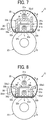
- the stay 33b has an upright portion (a contact portion) 33b1 that extends in the direction perpendicular to the sheet conveyance direction and different from the width direction of the fixing belt 22 and contacts the nip formation member 32 at one end of the upright portion 33b1 and a bent portion 33b2 that is continuously bent from the upright portion 33b1 toward upstream in the sheet conveyance direction.
- the bent portion 33b2 is disposed between the heaters 31a and 31b. That is, the bent portion 33b2 is the shield portion to block the heat transfer between the heaters 31a and 31b, and, in the present embodiment, the stay 33b also functions as the heat shield.
- the bent portion 34b of the heat shield 34 and the bent portion 33b2 of the stay 33 are disposed between the heaters 31a and 31b.
- An air layer exists between the bent portion 34b and the bent portion 33b2. That is, between the heaters 31a and 31b, there are the bent portion 34b, the air layer, and the bent portion 33b2.
- the stay 33 is bent in the middle so that the upper end of the stay 33b, that is, the upper end surface of the bent portion 33b2 is under the halogen heater 31a in FIG. 7 , the radiant heat of the heater 31a reaches a larger area on the fixing belt 22 than that of the above-described embodiments.
- the stay 33 may be bent in a direction away from the halogen heater 31a.
- the stays 33a and 33b have the upright portions 33a1 and 33b1 and the curved portions 33a3 and 33b3 continuously provided on the upright portions 33a1 and 33b1 and bent outward in the radial direction of the fixing belt 22 in a direction away from the heater 31a, respectively.
- the above-described structure can increase the area on the fixing belt 22 that the radiant heat of the heater 31a reaches because the upper end of the stays 33a and 33b and the heat shield 34 is under the heater 31a.
- both the stays 33a and 33b have the curved portions 33a3 and 33b3, respectively, but either one of the stays 33a and 33b may have the bent portion.
- a coated surface 40 may be provided on the surface of the heat shield 34.
- Coating the coated surface 40 with a black coating agent having a higher absorption coefficient of heat or light, which is the infrared light in the present embodiment, than the surface of the heat shield 34 enables the heat shield 34 to efficiently absorb the heat from the heaters 31a and 31b and transfer a large amount of heat to the nip formation member 32. Therefore, the above-described structure can efficiently heat the fixing belt 22 in the fixing nip N.
- the coated surface 40 may be coated with a coating agent having a higher reflectance for heat or light, which is the infrared light in the present embodiment, than the surface of the heat shield 34.
- the above-described structure can increase an amount of heat reflected from the heat shield 34 to the fixing belt 22 and the nip formation member 32 among the heat radiated from the heaters 31a and 31b to the heat shield 34. Increasing the amount of heat reflected from the heat shield 34 prevents the heat shield 34 from overheating.
- the heat shield 34 since the heat shield 34 is in contact with the nip formation member 32 and transfers heat to the nip formation member 32 as described above, the heat shield 34 is unlikely to reach a high temperature. Therefore, even if the heaters 31a and 31b generates heat for a long time, the above-described structure can prevent the decrease in the reflectance of the heat shield 34 caused by the high temperature discoloration of the heat shield 34.
- a coated surface 40a facing the heater 31a may be coated with the coating agent having the high reflectance for the infrared light
- a coated surface 40b facing the heater 31b may be coated with the black coating agent having high absorption coefficient for the infrared light.
- the infrared light reflected by the heat shield 34 increases the radiant heat that reaches the fixing belt 22 from the heater 31a, which enables the heater 31a to efficiently heat an upper portion of the fixing belt 22 in FIG. 9 .
- increase in the amount of radiant heat of the heater 31b absorbed by the coated surface 40b of the heat shield 34 increases the amount of heat transferred from the heat shield 34 to the nip formation member 32.
- a coated surface 41 may be provided on the surfaces facing the heater 31a of the curved portions 33a3 and 33b3 of the stays 33.
- the coated surface 41 may be coated with the coating agent having the higher reflectance for heat or light, which is the infrared light in the present embodiment, than the surfaces facing the heater 31a of the curved portions 33a3 and 33b3.
- the above-described structure reduces the radiant heat radiated from the heater 31a and absorbed by the stay 33 and can efficiently heat the fixing belt 22.
- the different types of coating agents may be combined and applied to such coated surfaces 40 and 41.
- the stays 33a and 33b illustrated in FIG. 9 or the like may have the coated surface.
- the coated surface described above may be disposed over the entire portion of the stay and the heat shield in the longitudinal direction or may be disposed on a part of the stay or the heat shield.
- An area of the coated surface may be set corresponding to heat generation areas of the heaters 31a and 31b.
- the coating agent is applied to a central portion of the surface facing the heater 31a in the longitudinal direction, that is, the width direction of the fixing belt, and an end portion facing the heater 31b in the longitudinal direction.
- the stay 33b (or stay 33a) may function as the heat shield, and the heat shield 34 may be obviated.
- the stay 33b that is downstream in the sheet conveyance direction out of the pair of stays 33a and 33b has a upright portion 33b1 as the contact portion that contacts the nip formation member 32 and a bent portion 33b2 as the heat shield that is bent downstream in the sheet conveyance direction and continuously disposed on the upright portion 33b1, and the stay 33b functions as the heat shield.
- the bent portion 33b2 is disposed between the heaters 31a and 31b and can block the heat transfer between the two heaters 31a and 31b.
- the stay 33b is in contact with the nip formation member 32 at one end of the stay 33b and can transfer the heat received from both the heaters 31a and 31b to the nip formation member 32.
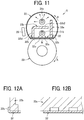
- a contact area of the stay 33b with the nip formation member 32 is larger than a contact area of the stay 33a with the nip formation member 32.
- the stays 33a and 33b are designed thicker than the heat shield 34 illustrated in FIG. 2 and designed to have a larger thermal capacity than the heat shield 34. Additionally, since the stay 33b has the bent portion 33b2 that receives a lot of heat amount from both heaters 31a and 31b, the stay 33a receives relatively smaller heat amount from both heaters 31a and 31b than the stay 33b and is less likely to reach a high temperature.
- the stay 33a has the contact area to support the nip formation member 32
- the stay 33b has the large contact area with the nip formation member 32 to facilitate heat transfer from the stay 33b to the nip formation member 32 when the heaters 31a and 31b generate heat and raise temperature largely.
- a method employed to design relatively large contact area of the stay 33b with the nip formation member 32 is, for example, as illustrated in FIG. 12A , designing a thickness of a part of one end portion of the stay 33b that contacts the nip formation member 32 larger than a part of the stay 33a that contacts the nip formation member 32, or, as illustrated in FIG. 12B , designing the stay 33a that is intermittently brought into contact with the nip formation member 32 in the longitudinal direction (the lateral direction in FIG. 12B ) to reduce the contact area.
- the stay 33b that also functions as the heat shield as described above can reduce the number of parts and the cost of the fixing device 5. Since the above-described configuration can design the stay 33b thicker and design the stay 33b to have a larger thermal capacity than a configuration having the heat shield and the stay separately, the temperature rise of the stay 33b is moderately even when the heaters 31a and 31b heat the stay 33b for a long time. In contrast, since the configuration described in the above embodiments having the heat shield and the stay separately can design the stay 33b thinner and design the stay 33b to have a smaller thermal capacity than the configuration in which the stay 33b functions as the heat shield, the configuration having the heat shield and the stay separately has an advantage that the stay 33b can efficiently transfer the heat to the nip formation member 32.
- the surface of the stays 33a and 33b as illustrated in FIG. 11 may be also coated with the black coating agent having the higher absorption coefficient of heat or light, which is the infrared light in the present embodiment, than the surface of the stays 33a and 33b to increase the absorption coefficient of the radiant heat from the heaters 31a and 31b,
- the surface of the stay 33a and 33b may be coated with the coating agent having the higher reflectance for heat or light, which is the infrared light in the present embodiment, than the surface of the stays 33a and 33b.
- these coating agents may be combined and applied to the stays 33a and 33b.
- the coating agent described above may be applied to a part of the stay in the longitudinal direction.
- the fixing device 5 includes the heat shield 42 facing the heater 31a, the heat shield 43 facing the heater 31b, and the stay 33 having the shield portion 332.
- the stay 33 has upright portions (contact portions) 331 that extend in the direction perpendicular to the sheet conveyance direction and the shield portion 332 that bridges both upright portions 331 on the opposite side of the nip formation member 32.
- the upright portions 331 are in contact with the backside surface of the nip formation portion 32a at both end portions in the sheet conveyance direction, that is, a left end portion and a right end portion in FIG. 13 , to reduce a bend of the nip formation portion 32a at both end portions in the sheet conveyance direction.
- the shield portion 332 is disposed between the heaters 31a and 31b in the cross-section perpendicular to the width direction of the fixing belt 22 to block the heat transfer between the heaters 31a and 31b.
- the stay 33 functions as the heat shield.
- the heat shield 42 has a substantially L-shaped cross section having a first portion extending in the sheet conveyance direction and disposed between the heaters 31a and 31b in the cross-section perpendicular to the width direction of the fixing belt 22 and a second portion extending from one end of the first portion in the direction perpendicular to the sheet conveyance direction.
- the first portion blocks heat transfer between the heaters 31a and 31b
- the second portion blocks a part of heat radiated from the heater 31a to the upstream side in the sheet conveyance direction.
- the heat shield 43 has upright portions that are both end portions in the sheet conveyance direction and extend in the direction perpendicular to the sheet conveyance direction and a shield portion that connects the upright portions and is disposed between the heaters 31a and 31b in the cross-section perpendicular to the width direction of the fixing belt 22 to block the heat transfer between the heaters 31a and 31b.
- the heat shield 43 covers the heater 31b but does not cover a portion facing the nip formation member 32.
- the upright portions of the heat shield 43 are in contact with the nip formation member 32 and transfer heat received from the heater 31b to the nip formation member 32.
- the heat shields 42 and 43 function as reflectors that reflect heat or light, which is the infrared light in the present embodiment. That is, the heat shields 42 and 43 are configured by members having high reflectance of the heat or light and can reflect the radiant heat that reaches the heat shields 42 and 43 from the heaters 31a and 31b.
- the above-described structure can prevent the heat shields 42 and 43 from overheating and improve heat efficiency of heating the fixing belt 22.
- the surface of the heat shield 42 facing the heater 31a and the surface of the heat shield 43 facing the heater 31b may be coated with the coating agent having a higher reflectance for heat or light than the surfaces of the heat shields 42 and 43.
- arranging the heat shield 42, the shield portion 332 of the stay 33, the air layer, and the heat shield 43 between the heaters 31a and 31b can efficiently prevent the heaters 31a and 31b from overheating each other.
- the heater 31b is covered with the heat shield 43 except for the portion facing the fixing nip N and can efficiently heat the portion facing the fixing nip N.
- the heat shield 34 has the bent portion 34b as the shield portion that extends in a direction inclined with respect to the nip formation member 32 and not parallel to the nip formation member 32.
- the bent portion 34b is inclined so that, with respect to one end of the bent portion 34b continuously connected to the upright portion 34a, the other end of the bent portion 34b is located at upper side in FIG. 15 , that is, the side closer to the heater 31a. Accordingly, the inclined bent portion 34b can be closer to the heater 31a than the bent portion parallel to the nip formation member 32 and efficiently reflect the radiant heat from the heater 31a to the fixing belt 22. Therefore, the heater 31a can efficiently heat the central portion of the fixing belt 22 in the width direction.
- the surface of the bent portion 34b facing the heater 31a has the coated surface 40a coated with the coating agent having higher reflectance for the infrared light than the surface of the bent portion 34b
- the surface of the stay 33 facing the heater 31a has the coated surface 41 coated with the coating agent having higher reflectance for the infrared light than the surface of the stay 33.
- the above-described structure can efficiently reflect the radiant heat from the heater 31a to the fixing belt 22.
- the surface of the bent portion 34b facing the heater 31b has the coated surface 40b coated with the coating agent having the higher absorption coefficient for the infrared light than the surface of the bent portion 34b to increase the heat amount transferred from the heat shield 34 to the nip formation member 32.
- the heat shield 34 may have a second bent portion 34d bent from the tip end of the bent portion 34b toward the stay 33a. According to the above, an outer circumferential surface of the heater 31b can be surrounded by the heat shield 34, the stay 33, and the nip formation member 32, which can efficiently transfer the radiant heat from the heater 31b to the nip formation member 32.
- bent portion 34b may be partially inclined in the longitudinal direction of the heat shield 34.
- the heat shield 34 may have an inclined portion in which the bent portion 34b is partially inclined corresponding to the heat generation area of the heater 31a and the other portion parallel to the nip formation member 32.
- the coated surface described above may be disposed on a part of the stay 33 in the longitudinal direction.
- the image forming apparatus is applicable not only to a monochrome image forming apparatus illustrated in FIG. 1 but also to a color image forming apparatus, a copier, a printer, a facsimile machine, or a multifunction peripheral including at least two functions of the copier, printer, and facsimile machine.
- the sheets P serving as recording media may be thick paper, postcards, envelopes, plain paper, thin paper, coated paper, art paper, tracing paper, overhead projector (OHP) transparencies, plastic film, prepreg, copper foil, and the like.
- OHP overhead projector
- blocking the heat transfer between the two heating members by the heat shield does not necessarily mean perfect block of the heat transfer.
- the meaning of blocking the heat transfer naturally includes a case in which a part of the heat transfer is blocked.
- heat transfer between the heaters 31a and 31b may occur through a gap between the right end of the bent portion 34b of the heat shield 34 and the stay 33. Even in this case, the heat shield 34 blocks a part of the heat transfer between the heaters 31a and 31b.
Landscapes
- Physics & Mathematics (AREA)
- General Physics & Mathematics (AREA)
- Fixing For Electrophotography (AREA)
Abstract
A fixing device (5) includes a fixing member (22), a pressing member (23), a nip formation member (32) pressed by the pressing member (23) via the fixing member (22), a plurality of heat generators (31a, 31b), and a shield (34) inside the fixing member (22) to block heat from the heat generators (31a, 31b). The plurality of heat generators (31a, 31b) includes one heat generator (31b) close to the nip formation member (32) and the other heat generator (31a) farther from the nip formation member (32) than the one heat generator (31b) in a direction that is perpendicular to a recording medium conveyance direction and is not a width direction of the fixing member (22). The shield (34) has a part disposed between the one heat generator (31b) and the other heat generator (31a) in a cross section that intersects the width direction of the fixing member (22).
Description
- Embodiments of the present disclosure generally relate to a fixing device and an image forming apparatus incorporating the fixing device.
- An image forming apparatus such as a copier, a printer, a facsimile machine, and a multi-functional apparatus including at least two functions of the copier, printer, facsimile machine includes a fixing device to convey a recording medium such as a sheet on which an unfixed image is formed to a fixing nip formed between a fixing member and a pressing member in the fixing device, heat the recording medium, and fix the unfixed image onto the recording medium.
- The fixing device includes a fixing belt as a cylindrical fixing member and a heat generator such as a halogen heater disposed inside a loop of the fixing belt to heat the fixing belt. The heat generator heats the fixing belt via a nip formation member disposed inside the loop of the fixing belt and raises a temperature of the fixing belt to a fixing temperature that enables fixing an image onto a recording medium. In the above-described fixing device, preferably, the heat generator quickly heats the fixing belt to make the high speed fixing device.
- For example,
JP-2016-35601-A - The fixing device including a plurality of heat generators inside the loop of the fixing member as described in
JP-2016-35601-A - Under the above-described circumstances, an object of the present disclosure is to prevent a plurality of heat generators from heating each other.
- It is a general object of the present disclosure to provide an improved and useful fixing device in which the above-mentioned disadvantages are eliminated. In order to achieve the above-mentioned object, there is provided a fixing device according to
claim 1. Advantageous embodiments are defined by the dependent claims. - Advantageously, the fixing device includes a fixing member in a cylindrical form, a pressing member configured to press an outer surface of the fixing member, a nip formation member disposed inside a loop of the fixing member, a plurality of heat generators disposed inside the loop of the fixing member and configured to heat the fixing member, and a shield disposed inside the loop of the fixing member and configured to block heat from the heat generators. The nip formation member is configured to be pressed by the pressing member via the fixing member to form a fixing nip. The plurality of heat generators includes one heat generator disposed close to the nip formation member and the other heat generator disposed farther from the nip formation member than the one heat generator in a direction that is perpendicular to a recording medium conveyance direction and is not a width direction of the fixing member. The shield has a part disposed between the one heat generator and the other heat generator in a cross section that intersects the width direction of the fixing member.
- According to the present disclosure, providing the shield between the one heat generator disposed near the nip formation member and the other heat generator disposed apart from the nip formation member can prevent the heat generators from heating each other.
- The aforementioned and other aspects, features, and advantages of the present disclosure would be better understood by reference to the following detailed description when considered in connection with the accompanying drawings, wherein:
-
FIG. 1 is a schematic diagram illustrating a configuration of an image forming apparatus according to an embodiment of the present disclosure; -
FIG. 2 is a vertical cross-sectional view of a fixing device according to a first embodiment of the present disclosure viewed from a lateral side of the fixing device; -
FIG. 3 is a perspective view of the fixing device with the vertical cross-sectional view of the fixing device; -
FIG. 4 is a vertical cross-sectional view of the fixing device viewed from a front side of the fixing device; -
FIG. 5 is a perspective view of a belt holder; -
FIG. 6 is a perspective view of a variation of the belt holder; -
FIG. 7 is a vertical cross-sectional view of a fixing device according to a second embodiment of the present disclosure viewed from a lateral side of the fixing device; -
FIG. 8 is a vertical cross-sectional view of a fixing device according to a third embodiment of the present disclosure viewed from a lateral side of the fixing device; -
FIG. 9 is a vertical cross-sectional view of a fixing device according to a fourth embodiment of the present disclosure viewed from a lateral side of the fixing device; -
FIG. 10 is a vertical cross-sectional view of a fixing device according to a fifth embodiment of the present disclosure viewed from a lateral side of the fixing device; -
FIG. 11 is a vertical cross-sectional view of a fixing device according to a sixth embodiment of the present disclosure viewed from a lateral side of the fixing device; -
FIGS. 12A and 12B are explanatory diagrams each illustrating a shape of one stay having a larger contact area with a nip formation member than the other stay; -
FIG. 13 is a vertical cross-sectional view of a fixing device according to a seventh embodiment of the present disclosure viewed from a lateral side of the fixing device; -
FIGS. 14A and 14B are perspective views each illustrating an example of a shape of a heat shield partially having an opening in an upright portion in a longitudinal direction of the heat shield illustrated inFIG. 2 ; -
FIG. 15 is a vertical cross-sectional view of a fixing device according to an eighth embodiment of the present disclosure viewed from a lateral side of the fixing device; and -
FIG. 16 is a vertical cross-sectional view of a fixing device viewed from a lateral side of the fixing device, which includes a modified heat shield different from the heat shield illustrated inFIG.15 . - The accompanying drawings are intended to depict embodiments of the present disclosure and should not be interpreted to limit the scope thereof. The accompanying drawings are not to be considered as drawn to scale unless explicitly noted.
- In describing embodiments illustrated in the drawings, specific terminology is employed for the sake of clarity. However, the disclosure of this specification is not intended to be limited to the specific terminology so selected and it is to be understood that each specific element includes all technical equivalents that have a similar function, operate in a similar manner, and achieve a similar result.
- Although the embodiments are described with technical limitations with reference to the attached drawings, such description is not intended to limit the scope of the disclosure and all of the components or elements described in the embodiments of this disclosure are not necessarily indispensable.
- Referring now to the drawings, embodiments of the present disclosure are described below. In the drawings illustrating the following embodiments, the same reference codes are allocated to elements (members or components) having the same function or shape and redundant descriptions thereof are omitted below.
-
FIG. 1 is a schematic diagram illustrating a configuration of an image forming apparatus according to an embodiment of the present disclosure. Referring toFIG. 1 , a configuration and operation of the image forming apparatus according to the present embodiment are described below. - An
image forming apparatus 1 illustrated inFIG. 1 is a monochrome electrophotographic laser printer. Theimage forming apparatus 1 according to the embodiments of the present disclosure may be a printer, a copier, a facsimile machine or a multifunction peripheral (MFP) having at least two of copying, printing, scanning, facsimile, and plotter functions. Theimage forming apparatus 1 is not limited to a monochrome image forming apparatus and may be a color image forming apparatus. - As illustrated in
FIG. 1 , theimage forming apparatus 1 includes animage forming device 2 to form an image, a recordingmedium feeding device 3 to feed a sheet P as a recording medium to theimage forming device 2, atransfer device 4 to transfer the image onto the fed sheet P, afixing device 5 to fix the image transferred onto the sheet P, and asheet ejection device 6 to eject the sheet P with the fixed image to an outside of theimage forming apparatus 1. - The
image forming device 2 includes a drum-shaped photoconductor 7, a charging roller 8 as a charging device to charge a surface of thephotoconductor 7, anexposure device 9 as a latent image forming device that exposes the surface of thephotoconductor 7 to form an electrostatic latent image on thephotoconductor 7, a developingroller 10 as a developing device that supplies toner as a developer to the surface of thephotoconductor 7 to visualize the electrostatic latent image, and acleaning blade 11 as a cleaner to clean the surface of thephotoconductor 7. - As an image forming operation start is instructed, in the
image forming device 2, thephotoconductor 7 starts to rotate, and the charging roller 8 uniformly charges the surface of thephotoconductor 7 to a high potential. Next, based on image data of an original document read by a scanner or print data instructed by a terminal device, theexposure device 9 exposes the surface of thephotoconductor 7. Potential of an exposed surface drops, and the electrostatic latent image is formed on thephotoconductor 7. The developingroller 10 supplies toner to the electrostatic latent image, thereby developing the latent image into the toner image on thephotoconductor 7. - The toner image formed on the
photoconductor 7 is transferred onto the sheet P in a transfer nip between thephotoconductor 7 and atransfer roller 15 disposed in thetransfer device 4. The sheet P is fed from the recordingmedium feeding device 3. In the recordingmedium feeding device 3, asheet feeding roller 13 feeds the sheet P from asheet tray 12 to a feeding path one by one. Atiming roller pair 14 sends out the sheet P fed from thesheet tray 12 to a transfer nip, timed to coincide with the toner image on thephotoconductor 7. The toner image on thephotoconductor 7 is transferred onto the sheet P at the transfer nip. After the toner image is transferred from thephotoconductors 7 onto the sheet P, thecleaning blade 11 removes residual toner on thephotoconductor 7. - The sheet P bearing the toner image is conveyed to the
fixing device 5. In thefixing device 5, heat and pressure when the sheet P passes through between a fixingbelt 22 and apressure roller 23 fixes the toner image onto the sheet P. Subsequently, the sheet P is conveyed to thesheet ejection device 6, and anejection roller pair 16 ejects the sheet P outside theimage forming apparatus 1, and a series of print operations are completed. - With reference to
FIGS. 2 to 6 , a detailed description is provided of a construction of the fixingdevice 5. -
FIG. 2 is a vertical cross-sectional view of the fixingdevice 5 viewed from a lateral side of the fixingdevice 5,FIG. 3 is a perspective view of the fixingdevice 5 with the vertical cross-sectional view of the fixingdevice 5, andFIG. 4 is a vertical cross-sectional view of the fixingdevice 5 viewed from a front side of the fixingdevice 5. In addition,FIG. 5 is a perspective view of abelt holder 35 to support the fixingbelt 22, andFIG. 6 is a perspective view of a variation of thebelt holder 35. - As illustrated in
FIG. 2 , the fixingdevice 5 includes the fixingbelt 22 as a fixing member, thepressure roller 23 as a pressing member, ahalogen heaters nip formation member 32, astay 33 as a contact member, and aheat shield 34. Thehalogen heaters nip formation member 32, thestay 33, and theheat shield 34 are members extending along a width direction of the fixingbelt 22 that is a direction perpendicular to a surface of a sheet ofFIG. 2 and a lateral direction inFIG. 4 . In the following description, the width direction of the fixingbelt 22 is simply referred to as the width direction. - As illustrated in
FIG. 2 , the fixingbelt 22 is a cylindrical fixing member to fix an unfixed image T to the sheet P and is disposed on the side of the sheet P on which the unfixed image T is held. The fixingbelt 22 in the present embodiment is an endless belt or film, including a base layer formed on an inner side of the fixingbelt 22 and made of a metal such as nickel and stainless steel (SUS) or a resin such as polyimide, and a release layer formed on the outer side of the fixingbelt 22 and made of tetrafluoroethylene-perfluoroalkylvinylether copolymer (PFA), polytetrafluoroethylene (PTFE), or the like. Optionally, an elastic layer made of rubber such as silicone rubber, silicone rubber foam, and fluoro rubber may be interposed between the base layer and the release layer. While the fixingbelt 22 and thepressure roller 23 press the unfixed toner image against the sheet P to fix the toner image onto the sheet P, the elastic layer having a thickness of about 100 micrometers elastically deforms to absorb slight surface asperities of the fixingbelt 22, preventing variation in gloss of the toner image on the sheet P. In the present embodiment, the fixingbelt 22 is thin and has a small loop diameter to decrease the thermal capacity of the fixingbelt 22. For example, the base layer of the fixingbelt 22 has a thickness of from 20 µm to 50 µm and the release layer has a thickness of from 10 µm to 50 µm. Thus, the fixingbelt 22 has a total thickness not greater than 1 mm. When the fixingbelt 22 includes the elastic layer, the thickness of the elastic layer may be set to 100 to 300 µm. In order to further decrease the thermal capacity of the fixingbelt 22, the fixingbelt 22 may have the total thickness not greater than 0.20 mm and preferably not greater than 0.16 mm. In the present embodiment, the fixingbelt 22 may have a loop diameter from 20 to 40 mm and preferably 30 mm or less. - The
pressure roller 23 is an opposed member disposed opposite an outer circumferential surface of the fixingbelt 22. Thepressure roller 23 includes a cored bar; an elastic layer coating the cored bar and being made of silicone rubber foam, fluoro rubber, or the like; and a release layer coating the elastic layer and being made of PFA, PTFE, or the like. According to the present embodiment, thepressure roller 23 is a solid roller. Alternatively, thepressure roller 23 may be a hollow roller. When thepressure roller 23 is the hollow roller, a heater such as a halogen heater may be disposed inside thepressure roller 23. The elastic layer of thepressure roller 23 may be made of solid rubber. Alternatively, if no heater is disposed inside thepressure roller 23, the elastic layer of thepressure roller 23 is preferably made of sponge rubber to enhance thermal insulation of thepressure roller 23. Such a configuration reduces heat conduction from the fixingbelt 22 to thepressure roller 23 and improves heating efficiency of the fixingbelt 22. - A driver disposed inside the
image forming apparatus 1 drives and rotates thepressure roller 23 in a direction indicated by arrow A inFIG. 2 . The rotation of thepressure roller 23 drives the fixingbelt 22 to rotate in a direction indicated by arrow B inFIG. 2 (hereinafter, belt rotation direction B) due to frictional force therebetween. - The
pressure roller 23 and the fixingbelt 22 are configured to be able to contact and separate from each other. If the sheet is jammed in the nip N, separating thepressure roller 23 and the fixingbelt 22 from each other and opening the nip N enables the jammed sheet to be removed. One of thepressure roller 23 and the fixingbelt 22 may be configured to be fixed and the other may be configured to be movable so that thepressure roller 23 and the fixingbelt 22 contact and separate from each other. Alternatively, both thepressure roller 23 and the fixingbelt 22 may be configured to move so that thepressure roller 23 and the fixingbelt 22 contact and separate from each other. - The
halogen heaters belt 22 and emitting infrared light, and radiant heat from thehalogen heaters belt 22 from the inside. In the present embodiment, oneheater 31a is positioned near thenip formation member 32, and theother heater 31b is positioned farther from thenip formation member 32 than theheater 31a. Theheaters FIG. 2 , that is, in a direction perpendicular to the fixing nip N. In the present embodiment, thehalogen heaters heater 31a heats a central portion of the fixingbelt 22 in the width direction of the fixingbelt 22, and theheater 31b heats end portions of the fixingbelt 22 in the width direction. - The
nip formation member 32 sandwiches the fixingbelt 22 together with thepressure roller 23, to form the fixing nip N. Specifically, thenip formation member 32 is disposed inside the loop of the fixingbelt 22 and extends in the longitudinal direction thereof parallel to the width direction of the fixingbelt 22. Thenip formation member 32 has a planar nipformation portion 32a that is in contact with an inner circumferential surface of the fixingbelt 22 and a pair ofcurved portions 32b that are bent from both end portions of thenip formation portion 32a in a belt rotation direction B to the opposite side to thepressure roller 23. - A pressing member such as a spring presses the
pressure roller 23 against thenip formation member 32, which causes thepressure roller 23 to contact the fixingbelt 22 and form the fixing nip N between thepressure roller 23 and the fixingbelt 22. When the sheet P is conveyed through the nip N, heat and pressure in the fixing nip N fixies the unfixed image T onto the surface of the sheet P. The conveyance direction of the sheet P in thefixing device 5 is a direction from the left to the right inFIG. 2 (see a direction indicated by arrow D1 inFIG. 2 ). - A
nip formation surface 32c on thenip formation portion 32a facing the fixingbelt 22 directly contacts the inner circumferential surface of the fixingbelt 22. Therefore, when the fixingbelt 22 rotates, the fixingbelt 22 slides along thenip formation surface 32c. In order to improve the abrasion resistance and the slidability of thenip formation surface 32c, preferably thenip formation surface 32c is treated with an alumite or a fluororesin material coating. Additionally, a lubricant such as a fluorine-based grease may be applied to thenip formation surface 32c to ensure slidability over time. In the present embodiment, thenip formation surface 32c is planar. Alternatively, thenip formation surface 32c may define a recess or other shape. For example, thenip formation surface 32c having a concave shape recessed to the side opposite to thepressure roller 23 leads the outlet of the sheet in the fixing nip N to be closer to thepressure roller 23, which improves separation of the sheet from the fixingbelt 22. - The
nip formation member 32 is made of a material having a thermal conductivity larger than a thermal conductivity of thestay 33. For example, the material of thenip formation member 32 is preferably copper (thermal conductivity: 398 W / mK) or aluminum (thermal conductivity: 236 W / mK). Thenip formation member 32 made of the material having such a large thermal conductivity absorbs the radiant heat from thehalogen heater 31b and effectively transfers heat to the fixingbelt 22. For example, setting the thickness of thenip formation member 32 to 1 mm or less can shorten a heat transfer time in which the heat transfers from thenip formation member 32 to the fixingbelt 22, which is advantageous in shortening a warm-up time of the fixingdevice 5. In contrast, setting the thickness of thenip formation member 32 to be larger than 1 mm but not larger than 5 mm can improve a heat storage capacity of thenip formation member 32. - The
stay 33 is the contact member that contacts a rear side surface of thenip formation member 32 to support thenip formation member 32 against the pressure of thepressure roller 23. In the present embodiment, thestays 33 are a pair of members provided on both sides of thenip formation member 32 in a sheet conveyance direction and extend in a direction perpendicular to the sheet conveyance direction that is a pressing direction of the pressure roller 23 (a vertical direction inFIG. 2 ), and one end of each stay 33 contacts thenip formation member 32. The stays 33 are provided on both sides of thehalogen heaters halogen heaters - When the
stay 33 supports thenip formation member 32, this means that a surface of thenip formation member 32 opposite thepressure roller 23 that is an upper surface inFIG. 2 contacts thestay 33 having a portion extending in the pressing direction of the pressure roller 23 (the vertical direction inFIG. 2 ) or a certain thick portion. Such a configuration reduces a bend of thenip formation member 32 caused by the pressing force from thepressure roller 23, in particular, the bend in the longitudinal direction of thenip formation member 32 in the present embodiment. The term "extending in the pressing direction" is not limited to "extending in the same direction as the pressing direction of thepressure roller 23" but includes "extending in a direction with a certain angle from the pressing direction of thepressure roller 23". Even in such cases, thestay 33 can reduce the bend of thenip formation member 32 against the pressing force from thepressure roller 23. - Extending the
stays 33 in the pressing direction of thepressure roller 23 strengthens the rigidity of thestay 33 in the pressing direction and reduces the bend of thenip formation portion 32a caused by the pressing force of thepressure roller 23. Such a configuration results in a uniform width of the nip in the longitudinal direction. In particular, when the stays 33 extending in the pressing direction as described above are disposed on both end portions of thenip formation portion 32a in the sheet conveyance direction, that is, right and left end portions of thenip formation portion 32a inFIG. 2 , thestays 33 can support both end portions of thenip formation portion 32a and efficiently reduce the bend of thenip formation portion 32a. Thestay 33 is preferably made of an iron-based metal such as stainless steel (SUS) or Steel Electrolytic Cold Commercial (SECC) that is electrogalvanized sheet steel to ensure rigidity. In addition, thestay 33 is made with a suitable thickness to ensure the rigidity and is thicker than theheat shield 34. - The
heat shield 34 is a member that blocks heat transfer between twohalogen heaters heat shield 34 has an upright portion (a contact portion) 34a that extends in a direction perpendicular to the sheet conveyance direction and contacts thenip formation member 32 at one end of theupright portion 34a and a bent portion (a shield portion) 34b that is continuously bent from theupright portion 34a toward downstream in the sheet conveyance direction. Thebent portion 34b is disposed between thehalogen heaters belt 22 that is a sheet surface inFIG. 2 and is the shield portion to block the heat transfer between thehalogen heaters heat shield 34 may be made by bending a metal plate. - When the above-described
fixing device 5 fixes the unfixed image T onto the sheet P, a driver disposed inside theimage forming apparatus 1 drives and rotates thepressure roller 23 in a direction indicated by arrow A inFIG. 2 . The fixingbelt 22 is driven and rotated by thepressure roller 23 as thepressure roller 23 rotates. At this time, the radiant heat from thehalogen heaters belt 22 to a fixing temperature. After the toner image is transferred onto the sheet P, the sheet P bearing the unfixed toner image T is conveyed to a fixing nip N between the fixingbelt 22 and thepressure roller 23. Therotating fixing belt 22 and therotating pressure roller 23 conveys the sheet P, and the sheet P passes through the fixing nip N. When the sheet P passes through the fixing nip N, heat and pressure applied to the sheet P fix the unfixed toner image T onto the sheet P. - As illustrated in
FIG. 4 , a pair ofbelt holders 35 is inserted in both lateral ends of the fixingbelt 22 in the axial direction of the fixingbelt 22 to rotatably support the fixingbelt 22. As described above, thebelt holders 35 inserted into the inner periphery of the fixingbelt 22 support the fixingbelt 22 in a state in which the fixingbelt 22 is not basically applied with tension in a circumferential direction thereof while the fixingbelt 22 does not rotate, that is, by a free belt system. - As illustrated in
FIGS. 3 to 5 , thebelt holders 35 include a C-shapedsupporter 35a inserted into the inner periphery of the fixingbelt 22 to support the fixingbelt 22 and aflange 35b that contacts an end face of the fixingbelt 22 to stop a movement of the fixingbelt 22 in the width direction, that is, walking of the fixingbelt 22 in the width direction. As illustrated inFIG. 6 , thesupporter 35a may have a cylindrical shape which is continuous over its entire circumference. As illustrated inFIG. 4 , each ofbelt holders 35 is fixed on a pair ofside plates 36 that are frames of the fixingdevice 5. Thebelt holder 35 has anopening 35c as illustrated inFIG. 5 , and both ends of thehalogen heaters stay 33 are fixed to theside plates 36 through theopenings 35c. Thehalogen heaters stay 33 may be fixed to thebelt holder 35. - Next, a description is provided of heating the fixing
belt 22 by thehalogen heaters - As illustrated in
FIG. 2 , thehalogen heaters halogen heaters - The
halogen heater 31a is sandwiched by thestays 33 in a lateral direction ofFIG. 2 , and thebent portion 34b of theheat shield 34 blocks downward heat transfer inFIG. 2 . Therefore, as indicated by arrows near thehalogen heater 31a inFIG. 2 , thehalogen heater 31a mainly heats an upper part of the fixingbelt 22 inFIG.2 . Thehalogen heater 31b is sandwiched by thestays 33 in the lateral direction ofFIG. 2 , and thebent portion 34b blocks upward heat transfer inFIG. 2 . Therefore, as indicated by arrows near thehalogen heater 31b inFIG. 2 , thehalogen heater 31b mainly heats the fixingbelt 22 in the fixing nip N via thenip formation member 32. - As described above, the
bent portion 34b disposed between the twohalogen heaters halogen heaters bent portion 34b can prevent thehalogen heaters halogen heaters bent portion 34b prevents thehalogen heaters belt 22. - In addition, in the present embodiment, contact between the
nip formation member 32 and an end of theupright portion 34a that is one portion of theheat shield 34 can transfer heat of theheat shield 34 to the fixingbelt 22 via thenip formation member 32. In particular, thebent portion 34b is disposed between theheaters belt 22 via thenip formation member 32 to efficiently heat the fixingbelt 22. Transferring the heat received by theheat shield 34 to the nipformation member 32 can prevent theheat shield 34 from being heated to a high temperature when theheaters heat shield 34 functions as a reflector that reflects radiant heat, the above-described structure can prevent a decrease in reflectance of theheat shield 34 caused by high-temperature discoloration of theheat shield 34. - The
heat shield 34 extends in the longitudinal direction that is the direction perpendicular to the surface of the sheet ofFIG. 2 , and a part of theheat shield 34 in the longitudinal direction may be cut out. For example, as illustrated inFIG. 14A , theheat shield 34 may have anopening 34c in a central portion of theupright portion 34a in the longitudinal direction. Providing theopening 34c in a portion of theheat shield 34 other than a portion disposed between theheaters bent portion 34b does not impair the shielding function of theheat shield 34 and can reduce the thermal capacity of theheat shield 34. Reducing the thermal capacity causes theheat shield 34 to easily heat, and an amount of heat in theheat shield 34 is efficiently transferred to the nipformation member 32 via theupright portion 34a. In particular, in the present embodiment, theheater 31b heats a longitudinal end portion of the nip formation member as a heating region, and providing theopening 34c in the portion of theheat shield 34 other than a portion corresponding to the heating region enables theheater 31b to efficiently heat theupright portion 34a. - Alternatively, as a configuration different from that of the present embodiment, when the
heater 31b heats a longitudinal center portion as the heating region, as illustrated inFIG. 14B , theheat shield 34 may have theupright portion 34a disposed in the longitudinal center portion of theheat shield 34 and reduce the thermal capacity of theheat shield 34. Note that each of theheat shields 34 illustrated inFIGS. 14A and 14B has a secondbent portion 34d extending in the sheet conveyance direction from one end of theupright portion 34a. - Hereinafter, other embodiments of the fixing
device 5 according to the present disclosure are described that have the stay and the heat shield different from the above-described embodiments. Redundant descriptions concerning the configurations similar to that of the above-described embodiments are omitted, focusing on the different configurations. - As illustrated in
FIG. 7 , in the present embodiment, among the pair ofstays fixing device 5, thestay 33b disposed upstream in the sheet conveyance direction is bent in the middle. Specifically, thestay 33b has an upright portion (a contact portion) 33b1 that extends in the direction perpendicular to the sheet conveyance direction and different from the width direction of the fixingbelt 22 and contacts thenip formation member 32 at one end of the upright portion 33b1 and a bent portion 33b2 that is continuously bent from the upright portion 33b1 toward upstream in the sheet conveyance direction. - The bent portion 33b2 is disposed between the
heaters heaters stay 33b also functions as the heat shield. - Thus, in the present embodiment, the
bent portion 34b of theheat shield 34 and the bent portion 33b2 of thestay 33 are disposed between theheaters bent portion 34b and the bent portion 33b2. That is, between theheaters bent portion 34b, the air layer, and the bent portion 33b2. Providing two shield portions with two different members between theheaters heaters - In the present embodiment, since the
stay 33 is bent in the middle so that the upper end of thestay 33b, that is, the upper end surface of the bent portion 33b2 is under thehalogen heater 31a inFIG. 7 , the radiant heat of theheater 31a reaches a larger area on the fixingbelt 22 than that of the above-described embodiments. - Alternatively, as illustrated in
FIG. 8 , thestay 33 may be bent in a direction away from thehalogen heater 31a. In the present embodiment, thestays belt 22 in a direction away from theheater 31a, respectively. The above-described structure can increase the area on the fixingbelt 22 that the radiant heat of theheater 31a reaches because the upper end of thestays heat shield 34 is under theheater 31a. In the present embodiment, both thestays stays - As illustrated in
FIG. 9 , acoated surface 40 may be provided on the surface of theheat shield 34. Coating thecoated surface 40 with a black coating agent having a higher absorption coefficient of heat or light, which is the infrared light in the present embodiment, than the surface of theheat shield 34 enables theheat shield 34 to efficiently absorb the heat from theheaters formation member 32. Therefore, the above-described structure can efficiently heat the fixingbelt 22 in the fixing nip N. - In contrast, the
coated surface 40 may be coated with a coating agent having a higher reflectance for heat or light, which is the infrared light in the present embodiment, than the surface of theheat shield 34. The above-described structure can increase an amount of heat reflected from theheat shield 34 to the fixingbelt 22 and thenip formation member 32 among the heat radiated from theheaters heat shield 34. Increasing the amount of heat reflected from theheat shield 34 prevents theheat shield 34 from overheating. In particular, in the present embodiment, since theheat shield 34 is in contact with thenip formation member 32 and transfers heat to the nipformation member 32 as described above, theheat shield 34 is unlikely to reach a high temperature. Therefore, even if theheaters heat shield 34 caused by the high temperature discoloration of theheat shield 34. - These coating agents may be combined and applied. For example, among the
coated surfaces 40 of theheat shield 34, acoated surface 40a facing theheater 31a may be coated with the coating agent having the high reflectance for the infrared light, and acoated surface 40b facing theheater 31b may be coated with the black coating agent having high absorption coefficient for the infrared light. As a result, the infrared light reflected by theheat shield 34 increases the radiant heat that reaches the fixingbelt 22 from theheater 31a, which enables theheater 31a to efficiently heat an upper portion of the fixingbelt 22 inFIG. 9 . In addition, increase in the amount of radiant heat of theheater 31b absorbed by thecoated surface 40b of theheat shield 34 increases the amount of heat transferred from theheat shield 34 to the nipformation member 32. - Additionally, as illustrated in
FIG. 10 , acoated surface 41 may be provided on the surfaces facing theheater 31a of the curved portions 33a3 and 33b3 of the stays 33. Thecoated surface 41 may be coated with the coating agent having the higher reflectance for heat or light, which is the infrared light in the present embodiment, than the surfaces facing theheater 31a of the curved portions 33a3 and 33b3. The above-described structure reduces the radiant heat radiated from theheater 31a and absorbed by thestay 33 and can efficiently heat the fixingbelt 22. Of course, as described above, the different types of coating agents may be combined and applied to suchcoated surfaces stays FIG. 9 or the like may have the coated surface. - The coated surface described above may be disposed over the entire portion of the stay and the heat shield in the longitudinal direction or may be disposed on a part of the stay or the heat shield. An area of the coated surface may be set corresponding to heat generation areas of the
heaters heater 31a in the longitudinal direction, that is, the width direction of the fixing belt, and an end portion facing theheater 31b in the longitudinal direction. The above-described structure can obviate unnecessary coating and reduce cost of coating. - Alternatively, the
stay 33b (or stay 33a) may function as the heat shield, and theheat shield 34 may be obviated. For example, in thefixing device 5 illustrated inFIG. 11 , thestay 33b that is downstream in the sheet conveyance direction out of the pair ofstays nip formation member 32 and a bent portion 33b2 as the heat shield that is bent downstream in the sheet conveyance direction and continuously disposed on the upright portion 33b1, and thestay 33b functions as the heat shield. - The bent portion 33b2 is disposed between the
heaters heaters stay 33b is in contact with thenip formation member 32 at one end of thestay 33b and can transfer the heat received from both theheaters formation member 32. - In the above configuration, preferably, a contact area of the
stay 33b with thenip formation member 32 is larger than a contact area of thestay 33a with thenip formation member 32. To support the back of thenip formation member 32, thestays heat shield 34 illustrated inFIG. 2 and designed to have a larger thermal capacity than theheat shield 34. Additionally, since thestay 33b has the bent portion 33b2 that receives a lot of heat amount from bothheaters stay 33a receives relatively smaller heat amount from bothheaters stay 33b and is less likely to reach a high temperature. Therefore, preferably, thestay 33a has the contact area to support thenip formation member 32, and thestay 33b has the large contact area with thenip formation member 32 to facilitate heat transfer from thestay 33b to the nipformation member 32 when theheaters stay 33b with thenip formation member 32 is, for example, as illustrated inFIG. 12A , designing a thickness of a part of one end portion of thestay 33b that contacts thenip formation member 32 larger than a part of thestay 33a that contacts thenip formation member 32, or, as illustrated inFIG. 12B , designing thestay 33a that is intermittently brought into contact with thenip formation member 32 in the longitudinal direction (the lateral direction inFIG. 12B ) to reduce the contact area. - The
stay 33b that also functions as the heat shield as described above can reduce the number of parts and the cost of the fixingdevice 5. Since the above-described configuration can design thestay 33b thicker and design thestay 33b to have a larger thermal capacity than a configuration having the heat shield and the stay separately, the temperature rise of thestay 33b is moderately even when theheaters stay 33b for a long time. In contrast, since the configuration described in the above embodiments having the heat shield and the stay separately can design thestay 33b thinner and design thestay 33b to have a smaller thermal capacity than the configuration in which thestay 33b functions as the heat shield, the configuration having the heat shield and the stay separately has an advantage that thestay 33b can efficiently transfer the heat to the nipformation member 32. - The surface of the
stays FIG. 11 may be also coated with the black coating agent having the higher absorption coefficient of heat or light, which is the infrared light in the present embodiment, than the surface of thestays heaters stay stays stays - Next, the fixing
device 5 according to the embodiment illustrated inFIG. 13 includes the heat shield 42 facing theheater 31a, theheat shield 43 facing theheater 31b, and thestay 33 having theshield portion 332. - Specifically, the
stay 33 has upright portions (contact portions) 331 that extend in the direction perpendicular to the sheet conveyance direction and theshield portion 332 that bridges bothupright portions 331 on the opposite side of thenip formation member 32. Theupright portions 331 are in contact with the backside surface of thenip formation portion 32a at both end portions in the sheet conveyance direction, that is, a left end portion and a right end portion inFIG. 13 , to reduce a bend of thenip formation portion 32a at both end portions in the sheet conveyance direction. Theshield portion 332 is disposed between theheaters belt 22 to block the heat transfer between theheaters stay 33 functions as the heat shield. - The heat shield 42 has a substantially L-shaped cross section having a first portion extending in the sheet conveyance direction and disposed between the
heaters belt 22 and a second portion extending from one end of the first portion in the direction perpendicular to the sheet conveyance direction. In the heat shield 42, the first portion blocks heat transfer between theheaters heater 31a to the upstream side in the sheet conveyance direction. - The
heat shield 43 has upright portions that are both end portions in the sheet conveyance direction and extend in the direction perpendicular to the sheet conveyance direction and a shield portion that connects the upright portions and is disposed between theheaters belt 22 to block the heat transfer between theheaters heat shield 43 covers theheater 31b but does not cover a portion facing thenip formation member 32. The upright portions of theheat shield 43 are in contact with thenip formation member 32 and transfer heat received from theheater 31b to the nipformation member 32. - In the present embodiment, the
heat shields 42 and 43 function as reflectors that reflect heat or light, which is the infrared light in the present embodiment. That is, theheat shields 42 and 43 are configured by members having high reflectance of the heat or light and can reflect the radiant heat that reaches theheat shields 42 and 43 from theheaters heat shields 42 and 43 from overheating and improve heat efficiency of heating the fixingbelt 22. Similar to the above described embodiments, the surface of the heat shield 42 facing theheater 31a and the surface of theheat shield 43 facing theheater 31b may be coated with the coating agent having a higher reflectance for heat or light than the surfaces of theheat shields 42 and 43. - In the present embodiment, arranging the heat shield 42, the
shield portion 332 of thestay 33, the air layer, and theheat shield 43 between theheaters heaters heater 31b is covered with theheat shield 43 except for the portion facing the fixing nip N and can efficiently heat the portion facing the fixing nip N. - Next, in the embodiment as illustrated in
FIG. 15 , theheat shield 34 has thebent portion 34b as the shield portion that extends in a direction inclined with respect to the nipformation member 32 and not parallel to the nipformation member 32. Specifically, thebent portion 34b is inclined so that, with respect to one end of thebent portion 34b continuously connected to theupright portion 34a, the other end of thebent portion 34b is located at upper side inFIG. 15 , that is, the side closer to theheater 31a. Accordingly, the inclinedbent portion 34b can be closer to theheater 31a than the bent portion parallel to the nipformation member 32 and efficiently reflect the radiant heat from theheater 31a to the fixingbelt 22. Therefore, theheater 31a can efficiently heat the central portion of the fixingbelt 22 in the width direction. - The surface of the
bent portion 34b facing theheater 31a has the coatedsurface 40a coated with the coating agent having higher reflectance for the infrared light than the surface of thebent portion 34b, and the surface of thestay 33 facing theheater 31a has the coatedsurface 41 coated with the coating agent having higher reflectance for the infrared light than the surface of thestay 33. The above-described structure can efficiently reflect the radiant heat from theheater 31a to the fixingbelt 22. In addition, the surface of thebent portion 34b facing theheater 31b has the coatedsurface 40b coated with the coating agent having the higher absorption coefficient for the infrared light than the surface of thebent portion 34b to increase the heat amount transferred from theheat shield 34 to the nipformation member 32. - Additionally, as illustrated in
FIG. 16 , theheat shield 34 may have a secondbent portion 34d bent from the tip end of thebent portion 34b toward thestay 33a. According to the above, an outer circumferential surface of theheater 31b can be surrounded by theheat shield 34, thestay 33, and thenip formation member 32, which can efficiently transfer the radiant heat from theheater 31b to the nipformation member 32. - The above-described
bent portion 34b may be partially inclined in the longitudinal direction of theheat shield 34. For example, in the longitudinal direction of theheat shield 34, theheat shield 34 may have an inclined portion in which thebent portion 34b is partially inclined corresponding to the heat generation area of theheater 31a and the other portion parallel to the nipformation member 32. Additionally, the coated surface described above may be disposed on a part of thestay 33 in the longitudinal direction. - The present disclosure is not limited to the details of the embodiments described above and various modifications and improvements are possible.
- The image forming apparatus according to the present embodiment of the present disclosure is applicable not only to a monochrome image forming apparatus illustrated in
FIG. 1 but also to a color image forming apparatus, a copier, a printer, a facsimile machine, or a multifunction peripheral including at least two functions of the copier, printer, and facsimile machine. - The sheets P serving as recording media may be thick paper, postcards, envelopes, plain paper, thin paper, coated paper, art paper, tracing paper, overhead projector (OHP) transparencies, plastic film, prepreg, copper foil, and the like.
- In the present disclosure, blocking the heat transfer between the two heating members by the heat shield does not necessarily mean perfect block of the heat transfer. The meaning of blocking the heat transfer naturally includes a case in which a part of the heat transfer is blocked. For example, in
FIG. 2 , heat transfer between theheaters bent portion 34b of theheat shield 34 and thestay 33. Even in this case, theheat shield 34 blocks a part of the heat transfer between theheaters - Numerous additional modifications and variations are possible in light of the above teachings. It is therefore to be understood that, within the scope of the above teachings, the present disclosure may be practiced otherwise than as specifically described herein. With some embodiments having thus been described, it will be obvious that the same may be varied in many ways. Such variations are not to be regarded as a departure from the scope of the present disclosure and appended claims, and all such modifications are intended to be included within the scope of the present disclosure and appended claims.
Claims (15)
- A fixing device (5) comprising:a fixing member (22) in a cylindrical form;a pressing member (23) configured to press an outer surface of the fixing member (22);a nip formation member (32) disposed inside a loop of the fixing member (22), the nip formation member (32) configured to be pressed by the pressing member (23) via the fixing member (22) to form a fixing nip;a plurality of heat generators (31a, 31b) disposed inside the loop of the fixing member (22) and configured to heat the fixing member (22), the plurality of heat generators (31a, 31b) including one heat generator (31b) disposed close to the nip formation member (32) and the other heat generator (31a) disposed farther from the nip formation member (32) than the one heat generator (31b) in a direction that is perpendicular to a recording medium conveyance direction and is not a width direction of the fixing member (22); anda shield (34) disposed inside the loop of the fixing member (22) and configured to block heat from the plurality of heat generators (31a, 31b), the shield (34) having a part disposed between the one heat generator (31b) and the other heat generator (31a) in a cross section that intersects the width direction of the fixing member (22).
- The fixing device (5) according to claim 1,
wherein the shield (34) contacts the nip formation member (32). - The fixing device (5) according to claim 2,
wherein the shield (34) contacts a surface of the nip formation member (32) on a side opposite to a side facing the pressing member (23). - The fixing device (5) according to claim 3, further comprising a contact member (33a) that is different from the shield (33b) and is configured to contact the surface of the nip formation member (32) on the side opposite to the side facing the pressing member (23),
wherein a contact area between the contact member (33a) and the nip formation member (32) is smaller than a contact area between the shield (33b) and the nip formation member (32). - The fixing device (5) according to claim 2, further comprising a contact member (33) disposed inside the loop of the fixing member (22),
wherein the contact member (33) is different from the shield (34) and is configured to contact a surface of the nip formation member (32) on a side opposite to a side facing the pressing member (23). - The fixing device (5) according to claim 5,
wherein the contact member (33) has:a contact portion (33a1, 33b1) contacting the nip formation member (32) and extending in a direction that intersects the recording medium conveyance direction and is not the width direction of the fixing member (22); anda curved portion (33a3, 33b3) extending from the contact portion (33a1, 33b1) in a direction that is away from the other heat generator (31a) and different from the direction in which the contact portion (33a1, 33b1) extends. - The fixing device (5) according to any one of claims 2 to 6,
wherein at least one of the contact member (33) and the shield (34) includes a coated surface disposed opposite one of the plurality of heat generators (31a, 31b) and coated with a coating agent having a higher reflectance than an uncoated surface of the at least one of the contact member (33) and the shield (34). - The fixing device (5) according to any one of claims 1 to 7, further comprising a plurality of shields (34) including the shield (34).
- The fixing device (5) according to any one of claims 1 to 8,
wherein the shield (34) includes a coated surface disposed opposite one of the plurality of heat generators (31a, 31b) and coated with a coating agent having a higher absorption coefficient than a surface of the shield (34). - The fixing device (5) according to any one of claims 1 to 8,
wherein the shield (34) includes a coated surface disposed opposite one of the plurality of heat generators (31a, 31b) and coated with a coating agent having a higher reflectance than a surface of the shield (34). - The fixing device (5) according to claim 9 or 10,
wherein the shield (34) includes:a coated surface disposed opposite the one heat generator (31b) and coated with the coating agent having a higher absorption coefficient than a surface of the shield (34); anda coated surface disposed opposite the other heat generator (31a) and coated with the coating agent having a higher reflectance than a surface of the shield (34). - The fixing device (5) according to any one of claims 9 to 11,
wherein an area of the coated surface corresponds to a heat generation area of one of the plurality of heat generators (31a, 31b) facing the coated surface in the width direction of the fixing member (22). - The fixing device (5) according to any one of claims 1 to 12,
wherein the shield (34) has:an upright portion (34a) extending in a direction that intersects the recording medium conveyance direction and is not the width direction of the fixing member (22); anda shield portion (34b) coupled to the upright portion (34a) and disposed between the one heat generator (31b) and the other heat generator (31a) in the cross section that intersects the width direction of the fixing member (22), at least part of the shield portion (34b) extending in an inclined direction with respect to the nip formation member (32) in the cross section that intersects the width direction of the fixing member (22), andwherein the inclined direction is a direction from one end of the shield portion (34b) coupled to the upright portion (34a) to another end of the shield portion (34b) closer to the other heat generator (31a) than a point at which said another end of the shield portion (34b) exists if the shield portion (34b) is parallel to the nip formation member (32). - The fixing device (5) according to claim 13,
wherein an inclined part of the shield portion (34b) corresponds to a heat generation area of the other heat generator (31a) in the width direction of the fixing member (22). - An image forming apparatus (1) comprising the fixing device (5) according to any one of claims 1 to 14.
Applications Claiming Priority (3)
| Application Number | Priority Date | Filing Date | Title |
|---|---|---|---|
| JP2019020538 | 2019-02-07 | ||
| JP2019038475 | 2019-03-04 | ||
| JP2019121360A JP7275468B2 (en) | 2019-02-07 | 2019-06-28 | Fixing device, image forming device |
Publications (1)
| Publication Number | Publication Date |
|---|---|
| EP3693802A1 true EP3693802A1 (en) | 2020-08-12 |
Family
ID=69375245
Family Applications (1)
| Application Number | Title | Priority Date | Filing Date |
|---|---|---|---|
| EP20154150.5A Withdrawn EP3693802A1 (en) | 2019-02-07 | 2020-01-28 | Fixing device and image forming apparatus incorporating same |
Country Status (1)
| Country | Link |
|---|---|
| EP (1) | EP3693802A1 (en) |
Citations (7)
| Publication number | Priority date | Publication date | Assignee | Title |
|---|---|---|---|---|
| JP2014041172A (en) * | 2012-08-21 | 2014-03-06 | Canon Inc | Heating device and image forming device |
| US20140169820A1 (en) * | 2012-12-14 | 2014-06-19 | Kyocera Document Solutions Inc. | Fixing device and image forming apparatus |
| JP2014238428A (en) * | 2012-09-14 | 2014-12-18 | 株式会社リコー | Fixing device and image forming apparatus |
| JP2015118238A (en) * | 2013-12-18 | 2015-06-25 | コニカミノルタ株式会社 | Fixing apparatus and image forming apparatus |
| JP2016035601A (en) | 2015-12-14 | 2016-03-17 | ブラザー工業株式会社 | Fixing device |
| US20160246228A1 (en) * | 2015-02-23 | 2016-08-25 | Ippei Fujimoto | Fixing device and image forming apparatus |
| JP2016212278A (en) * | 2015-05-11 | 2016-12-15 | 株式会社リコー | Fixing device and image forming apparatus |
-
2020
- 2020-01-28 EP EP20154150.5A patent/EP3693802A1/en not_active Withdrawn
Patent Citations (7)
| Publication number | Priority date | Publication date | Assignee | Title |
|---|---|---|---|---|
| JP2014041172A (en) * | 2012-08-21 | 2014-03-06 | Canon Inc | Heating device and image forming device |
| JP2014238428A (en) * | 2012-09-14 | 2014-12-18 | 株式会社リコー | Fixing device and image forming apparatus |
| US20140169820A1 (en) * | 2012-12-14 | 2014-06-19 | Kyocera Document Solutions Inc. | Fixing device and image forming apparatus |
| JP2015118238A (en) * | 2013-12-18 | 2015-06-25 | コニカミノルタ株式会社 | Fixing apparatus and image forming apparatus |
| US20160246228A1 (en) * | 2015-02-23 | 2016-08-25 | Ippei Fujimoto | Fixing device and image forming apparatus |
| JP2016212278A (en) * | 2015-05-11 | 2016-12-15 | 株式会社リコー | Fixing device and image forming apparatus |
| JP2016035601A (en) | 2015-12-14 | 2016-03-17 | ブラザー工業株式会社 | Fixing device |
Similar Documents
| Publication | Publication Date | Title |
|---|---|---|
| US10935911B2 (en) | Fixing device capable of enhancing durability of endless belt and image forming apparatus incorporating the same | |
| US8971779B2 (en) | Fixing device with support and image forming apparatus incorporating same | |
| US8989643B2 (en) | Fixing device with endless belt and image forming apparatus incorporating same | |
| US9046833B2 (en) | Fixing device and image forming apparatus incorporating same | |
| US9116481B2 (en) | Fixing device including a reflector and image forming apparatus | |
| US9405239B2 (en) | Fixing device, image forming apparatus, and fixing method | |
| US9046839B2 (en) | Fixing device including a heat shield and image forming apparatus | |
| US9348272B2 (en) | Fixing device including a reinforced heat shield and image forming apparatus | |
| US8886103B2 (en) | Fixing device capable of minimizing damage of endless belt and image forming apparatus incorporating same | |
| US9158248B2 (en) | Fixing device and image forming apparatus | |
| US9164445B2 (en) | Fixing device and image forming apparatus | |
| US9494901B2 (en) | Fixing device and image forming apparatus with a rotatable light shield | |
| US9897950B2 (en) | Fixing device and image forming apparatus | |
| US10152006B2 (en) | Fixing device and image forming apparatus | |
| EP3709094B1 (en) | Fixing device and image forming apparatus incorporating same | |
| EP3690550A1 (en) | Fixing device and image forming apparatus incorporating same | |
| EP3690551A1 (en) | Fixing device and image forming apparatus incorporating same | |
| EP3761120A1 (en) | Heating device, fixing device, and image forming apparatus | |
| EP3699690A1 (en) | Heating device, fixing device, and image forming apparatus | |
| JP6213890B2 (en) | Fixing apparatus and image forming apparatus | |
| EP3667430B1 (en) | Fixing device and image forming apparatus incorporating same | |
| EP3629097A1 (en) | Fixing device and image forming apparatus incorporating the same | |
| JP6826774B2 (en) | Fixing device and image forming device | |
| JP7275468B2 (en) | Fixing device, image forming device | |
| EP3663861A1 (en) | Heating device, fixing device, and image forming apparatus |
Legal Events
| Date | Code | Title | Description |
|---|---|---|---|
| PUAI | Public reference made under article 153(3) epc to a published international application that has entered the european phase |
Free format text: ORIGINAL CODE: 0009012 |
|
| STAA | Information on the status of an ep patent application or granted ep patent |
Free format text: STATUS: REQUEST FOR EXAMINATION WAS MADE |
|
| 17P | Request for examination filed |
Effective date: 20200128 |
|
| AK | Designated contracting states |
Kind code of ref document: A1 Designated state(s): AL AT BE BG CH CY CZ DE DK EE ES FI FR GB GR HR HU IE IS IT LI LT LU LV MC MK MT NL NO PL PT RO RS SE SI SK SM TR |
|
| AX | Request for extension of the european patent |
Extension state: BA ME |
|
| STAA | Information on the status of an ep patent application or granted ep patent |
Free format text: STATUS: THE APPLICATION HAS BEEN WITHDRAWN |
|
| 18W | Application withdrawn |
Effective date: 20211220 |