EP3693727A1 - Method for measuring degree of orientation of fibers, device for measuring degree of orientation of fibers, and program for controlling device for measuring degree of orientation of fibers - Google Patents
Method for measuring degree of orientation of fibers, device for measuring degree of orientation of fibers, and program for controlling device for measuring degree of orientation of fibers Download PDFInfo
- Publication number
- EP3693727A1 EP3693727A1 EP18864002.3A EP18864002A EP3693727A1 EP 3693727 A1 EP3693727 A1 EP 3693727A1 EP 18864002 A EP18864002 A EP 18864002A EP 3693727 A1 EP3693727 A1 EP 3693727A1
- Authority
- EP
- European Patent Office
- Prior art keywords
- orientation degree
- diffraction
- fiber orientation
- graphite
- angle
- Prior art date
- Legal status (The legal status is an assumption and is not a legal conclusion. Google has not performed a legal analysis and makes no representation as to the accuracy of the status listed.)
- Granted
Links
Images




Classifications
-
- G—PHYSICS
- G01—MEASURING; TESTING
- G01N—INVESTIGATING OR ANALYSING MATERIALS BY DETERMINING THEIR CHEMICAL OR PHYSICAL PROPERTIES
- G01N23/00—Investigating or analysing materials by the use of wave or particle radiation, e.g. X-rays or neutrons, not covered by groups G01N3/00 – G01N17/00, G01N21/00 or G01N22/00
- G01N23/20—Investigating or analysing materials by the use of wave or particle radiation, e.g. X-rays or neutrons, not covered by groups G01N3/00 – G01N17/00, G01N21/00 or G01N22/00 by using diffraction of the radiation by the materials, e.g. for investigating crystal structure; by using scattering of the radiation by the materials, e.g. for investigating non-crystalline materials; by using reflection of the radiation by the materials
- G01N23/2055—Analysing diffraction patterns
-
- G—PHYSICS
- G01—MEASURING; TESTING
- G01N—INVESTIGATING OR ANALYSING MATERIALS BY DETERMINING THEIR CHEMICAL OR PHYSICAL PROPERTIES
- G01N23/00—Investigating or analysing materials by the use of wave or particle radiation, e.g. X-rays or neutrons, not covered by groups G01N3/00 – G01N17/00, G01N21/00 or G01N22/00
- G01N23/20—Investigating or analysing materials by the use of wave or particle radiation, e.g. X-rays or neutrons, not covered by groups G01N3/00 – G01N17/00, G01N21/00 or G01N22/00 by using diffraction of the radiation by the materials, e.g. for investigating crystal structure; by using scattering of the radiation by the materials, e.g. for investigating non-crystalline materials; by using reflection of the radiation by the materials
- G01N23/207—Diffractometry using detectors, e.g. using a probe in a central position and one or more displaceable detectors in circumferential positions
-
- G—PHYSICS
- G01—MEASURING; TESTING
- G01N—INVESTIGATING OR ANALYSING MATERIALS BY DETERMINING THEIR CHEMICAL OR PHYSICAL PROPERTIES
- G01N2223/00—Investigating materials by wave or particle radiation
- G01N2223/05—Investigating materials by wave or particle radiation by diffraction, scatter or reflection
- G01N2223/056—Investigating materials by wave or particle radiation by diffraction, scatter or reflection diffraction
- G01N2223/0566—Investigating materials by wave or particle radiation by diffraction, scatter or reflection diffraction analysing diffraction pattern
-
- G—PHYSICS
- G01—MEASURING; TESTING
- G01N—INVESTIGATING OR ANALYSING MATERIALS BY DETERMINING THEIR CHEMICAL OR PHYSICAL PROPERTIES
- G01N2223/00—Investigating materials by wave or particle radiation
- G01N2223/30—Accessories, mechanical or electrical features
- G01N2223/303—Accessories, mechanical or electrical features calibrating, standardising
-
- G—PHYSICS
- G01—MEASURING; TESTING
- G01N—INVESTIGATING OR ANALYSING MATERIALS BY DETERMINING THEIR CHEMICAL OR PHYSICAL PROPERTIES
- G01N2223/00—Investigating materials by wave or particle radiation
- G01N2223/30—Accessories, mechanical or electrical features
- G01N2223/306—Accessories, mechanical or electrical features computer control
Definitions
- the present invention relates to a method for measuring a fiber orientation degree of a composite material containing discontinuous carbon fibers, a fiber orientation degree measurement apparatus, and a control program for a fiber orientation degree measurement apparatus.
- Caron fiber reinforced plastics with improved strength by blending carbon fibers into plastics are being used for various uses.
- Information on a fiber orientation degree that is, a level of presence in each direction at which carbon fibers present in CFRP are present, is important technical information for the properties of CFRP and determination of phenomena during molding.
- Examples of known means for measuring information on the distribution of carbon fibers in CFRP include X-ray computer tomography (CT), X-ray transmission imaging, and microscopic observation of polished surfaces; they have problems in that it takes time for pretreatment and measurement apparatuses are expensive.
- CT computer tomography
- X-ray transmission imaging X-ray transmission imaging
- microscopic observation of polished surfaces they have problems in that it takes time for pretreatment and measurement apparatuses are expensive.
- a method in which X-ray diffractometry is used, respective X-ray diffraction images are acquired for a sample for which the orientation degree is desired to be measured and a control sample in which carbon fibers are unidirectionally oriented, crystal orientation degrees from pieces of diffraction information of the respective samples are calculated, and a fiber orientation degree of the sample is calculated by removing the influence of a matrix resin in CFRP from a crystal orientation degree of the sample using a crystal orientation degree of the control sample (refer to Patent Literature 1, for example).
- Patent Literature 1 Japanese Patent Application Laid-open No. 2016-90259
- Patent Literature 1 the control sample is required to be prepared, and the orientation degree cannot simply be calculated.
- the crystal orientation degree calculated in Patent Literature 1 is a two-dimensional (in-plane) crystal orientation degree, in which fiber distribution in a thickness direction of the sample is not considered, and is difficult to use for a sample in which fiber orientation varies in the thickness direction.
- the present invention has been made in view of the above, and an object thereof is to provide a method for measuring a fiber orientation degree, a fiber orientation degree measurement apparatus, and a control program for a fiber orientation degree measurement apparatus considering fiber orientation in a thickness direction simply and accurately.
- a method for measuring a fiber orientation degree includes: a diffraction image acquisition process of irradiating a sample formed of a composite material containing discontinuous carbon fibers with an X-ray to acquire an X-ray diffraction image; a peak angle calculation process of calculating an angle (2 ⁇ ) A of a peak originating from a crystal face of graphite from an inflection point A of an integral value I(2 ⁇ ) obtained by integrating the X-ray diffraction image with respect to an azimuth angle ( ⁇ ); a correction coefficient calculation process of calculating a correction coefficient ⁇ of a thickness of the sample; an upper limit calculation process of calculating an upper limit (2 ⁇ ) B of the peak of the crystal face of graphite from an inflection point B of the integral value I(2 ⁇ ); a diffraction sensitivity calculation process of calculating a diffraction sensitivity I c ( ⁇ ) of the peak originating from the crystal face of graphite
- a size of a film that is used for obtain the diffraction image is larger than L ⁇ tan(2ar A .
- the diffraction sensitivity calculation process includes setting an angular integrating range to be from (2 ⁇ ) A - ⁇ to (2 ⁇ ) A + ⁇ when (2 ⁇ ) A + ⁇ > (2 ⁇ ) B and setting the angular integrating range to be from (2 ⁇ ) A - ⁇ to (2 ⁇ ) B when (2 ⁇ ) A + ⁇ ⁇ (2 ⁇ ) B .
- the diffraction sensitivity calculated at the diffraction sensitivity calculation process is a sum of diffraction sensitivities of crystal faces [002], [004], and [006] of graphite.
- the orientation degree calculation process includes calculating the fiber orientation degree Sd( ⁇ ) by Expressions (2), (3), and (4) below:
- S 0 ⁇ ⁇ ⁇ / 2 ⁇ 90 ° + ⁇ / 2 + 90 ° I C ⁇ d ⁇
- S 1 ⁇ ⁇ ⁇ ⁇ / 2 ⁇ 90 ° + ⁇ / 2 + 90 ° I C ⁇ ⁇ cos 2 ⁇ d ⁇ 0 in Expression 3
- ⁇ ⁇ - ⁇ 0 .
- Sd ⁇ 3 ⁇ S 1 ⁇ / S 0 ⁇ 1 / 2
- a fiber orientation degree measurement apparatus includes: a diffraction image acquisition unit configured to irradiate a sample formed of a composite material containing discontinuous carbon fibers with an X-ray to acquire an X-ray diffraction image; a peak angle calculation unit configured to calculate an angle (2 ⁇ ) A of a peak originating from a crystal face of graphite from an inflection point A of an integral value I(2 ⁇ ) obtained by integrating the X-ray diffraction image with respect to an azimuth angle ( ⁇ ) ; a correction coefficient calculation unit configured to calculate a correction coefficient ⁇ of a thickness of the sample; an upper limit calculation unit configured to calculate an upper limit (2 ⁇ ) B of the peak of the crystal face of graphite from an inflection point B of the integral value I(2 ⁇ ); a diffraction sensitivity calculation unit configured to calculate a diffraction sensitivity I c ( ⁇ ) of the peak originating from the crystal face of graphite by correcting an integrating range with the correction coefficient ⁇
- a control program for a fiber orientation degree measurement apparatus executes: a diffraction image acquisition procedure of irradiating a sample formed of a composite material containing discontinuous carbon fibers with an X-ray to acquire an X-ray diffraction image; a peak angle calculation procedure of calculating an angle (2 ⁇ ) A of a peak originating from a crystal face of graphite from an inflection point A of an integral value I(2 ⁇ ) obtained by integrating the X-ray diffraction image with respect to an azimuth angle ( ⁇ ); a correction coefficient calculation procedure of calculating a correction coefficient ⁇ of a thickness of the sample; an upper limit calculation procedure of calculating an upper limit (2 ⁇ ) B of the peak of the crystal face of graphite from an inflection point B of the integral value I(2 ⁇ ); a diffraction sensitivity calculation procedure of calculating a diffraction sensitivity I c ( ⁇ ) of the peak originating from the crystal face of graphite by correcting an integrating range with the correction
- the method for measuring a fiber orientation degree, the fiber orientation degree measurement apparatus, and the control program for a fiber orientation degree measurement apparatus of the present invention do not need to produce a standard sample, also consider fiber orientation in the thickness direction of the sample, and can thus calculate the orientation degree of the carbon fibers in CFRP simply and more accurately.
- FIG. 1 is a block diagram of a fiber orientation degree measurement apparatus 100 according to an embodiment of the present invention.
- the fiber orientation degree measurement apparatus 100 includes a diffraction image acquisition unit 10, a controller 20 controlling units, and a display unit 30 displaying a measured fiber orientation degree.
- the diffraction image acquisition unit 10 irradiates sample formed of a composite material containing discontinuous carbon fibers with an X-ray to acquire an X-ray diffraction image (a Debye ring).
- the fiber orientation degree measurement apparatus 100 of the present invention acquires the X-ray diffraction image using a characteristic X-ray such as the Cu-K ⁇ line.
- the fiber orientation degree measurement apparatus 100 of the present invention is suitable for measurement of an orientation degree of the discontinuous carbon fibers in CFRP and can also be used for measurement of a fiber orientation degree in a mat formed of discontinuous carbon fibers containing no matrix resin.
- the discontinuous carbon fibers may be any of PAN-based and pitch-based carbon fibers.
- the matrix resin can be the sample of the present invention when any of a thermosetting resin, a thermoplastic resin, and a resin containing both a thermosetting resin and a thermoplastic resin is used so long as they are resins used for CFRP.
- the X-ray diffraction image can be acquired by irradiating the sample with an X-ray and receiving the X-ray reflected on a crystal face of the sample with a film (a camera) or an X-ray detector such as a flat panel detector (FPD).
- the X-ray diffraction image can be obtained by irradiating the sample (with a width of 5 to 10 mm, a length of 15 to 25 mm, and a thickness of 0.1 to 10 mm) with the characteristic X-ray (the Cu-K ⁇ line) for 10 minutes.
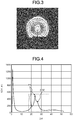
- FIG. 3 is a diagram of an exemplary X-ray diffraction image according to the embodiment of the present invention.
- FIG. 3 is a diagram of an exemplary X-ray diffraction image according to the embodiment of the present invention.
- FIG. 3 is an X-ray diffraction image of CFRP containing nylon 6 (polyamide 6) as the matrix resin, in which a double ring (a Debye ring) originating from a polyamide crystal is observed (a shadow projected at the lower part of the X-ray diffraction image is a shadow of an apparatus applying the X-ray).
- the controller 20 has a peak angle calculation unit 21, a correction coefficient calculation unit 22, an upper limit calculation unit 23, a diffraction sensitivity calculation unit 24, and an orientation degree calculation unit 25.
- the controller 20 is implemented by using a central processing unit (CPU) executing various kinds of processing programs, a read only memory (ROM) storing therein the various kinds of processing programs and the like in advance, and a random access memory (RAM) storing therein an arithmetic orientation degree of each processing and the like.
- a general-purpose computer such as a work station or a personal computer can be used.
- the peak angle calculation unit 21 extracts a diffraction pattern with a certain azimuth angle ( ⁇ ) from the X-ray diffraction image acquired by the diffraction image acquisition unit 10 and calculates an angle (2 ⁇ ) A of a peak originating from a crystal face of graphite from an inflection point of an integral value of the diffraction pattern.
- the X-ray diffraction image indicates a relation between a diffraction angle (2 ⁇ ) and a diffraction sensitivity I(2 ⁇ , ⁇ ) of the X-ray reflected on the crystal face of the sample, which is, for example, the polyamide crystal or the crystal face [002], [004], [006], or the like of graphite, and the azimuth angle ( ⁇ ).
- the peak angle calculation unit 21 calculates the angle (2 ⁇ ) A of the peak originating from the crystal face of graphite from a diffraction pattern in a direction of the azimuth angle ( ⁇ ), that is, a diffraction pattern in a circumferential direction from the center of the X-ray diffraction image in the direction of the azimuth angle ( ⁇ ).
- ⁇ azimuth angle
- the following describes calculation of the angle (2 ⁇ ) A of the peak originating from the crystal face [002], which gives the highest diffraction sensitivity.
- FIG. 4 is a diagram of an exemplary diffraction pattern at the azimuth angle ( ⁇ ) of the X-ray diffraction image in FIG. 3 .
- peaks with a diffraction angle (2 ⁇ ) of around 20° and 24.5° originate from the polyamide crystal, whereas a peak of a shoulder of the peak of polyamide around 24.5° is a peak originating from the crystal face [002] of graphite.
- the peak angle calculation unit 21 integrates the X-ray diffraction image in FIG. 3 in the direction of the azimuth angle ( ⁇ ) according to Expression (5) below to calculate the angle (2 ⁇ ) A of the peak of the crystal face [002] of graphite from the inflection point.
- I 2 ⁇ ⁇ ⁇ ⁇ / 2 ⁇ 90 ° + ⁇ / 2 + 90 ° I 2 ⁇ , ⁇ d ⁇
- the reason why the integrating range is from - ⁇ /2 (-90°) to + ⁇ /2 (+90°) is to exclude the influence of a shadow projected on the X-ray diffraction image.
- the X-ray diffraction image may be integrated from - ⁇ (-180°) to + ⁇ (+180°) .
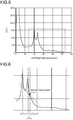
- FIG. 5 is a diagram of a relation between an integral value I(2 ⁇ ) obtained by integrating the X-ray diffraction image in FIG. 3 with respect to the azimuth angle ( ⁇ ) and the diffraction angle (2 ⁇ ).
- FIG. 6 is an enlarged view of the part indicated by the dotted line in FIG. 5 (near the diffraction angle of the crystal face [002] of graphite).
- An inflection point A appearing near the diffraction angle 2 ⁇ of the crystal face [002] of graphite of the integral value I(2 ⁇ ) illustrated in FIG. 5 is the angle (2 ⁇ ) A of the peak of the crystal face [002] of graphite.
- the peak angle (2 ⁇ ) A originating from the [002] face can be determined by referring to the diffraction angle 2 ⁇ (25.9 to 26.6°) of the crystal face [002] of general graphite illustrated in FIG. 7 and calculating a differential coefficient from above the diffraction angle 2 ⁇ (25.9 to 26.6°) of the crystal face [002].
- the diffraction angle 2 ⁇ of the crystal face of graphite varies by conditions when a graphite crystal is generated
- the diffraction angle 2 ⁇ of the crystal face [002] of the discontinuous carbon fibers used as the sample is considered to be near the diffraction angle 2 ⁇ (25.9 to 26.6°) of the crystal face [002] illustrated in FIG. 7
- the inflection point A can be determined by calculating the differential coefficient near the diffraction angle 2 ⁇ (25.9 to 26.6°) of the crystal face [002].
- the correction coefficient calculation unit 22 calculates a correction coefficient ⁇ of a thickness t (mm) of the sample.
- the correction coefficient ⁇ can be calculated by Expression (1) below.
- ⁇ 2 ⁇ A ⁇ tan ⁇ 1 1 ⁇ t / L ⁇ tan 2 ⁇ A
- t indicates the thickness (mm) of the sample
- L indicates a distance (mm) from an incident plane of the X-ray of the sample to a film surface on which the X-ray diffraction image is projected.
- the diffraction angle (2 ⁇ ) on the horizontal axis of the diffraction pattern in FIG. 4 includes information in a direction of the thickness t of the sample, and the peak angle (2 ⁇ ) A is corrected with the correction coefficient ⁇ . With this correction, a fiber orientation degree with fiber orientation not only in the two-dimensional (in-plane) direction of the sample but also in the thickness direction taken into account can be measured.
- the upper limit calculation unit 23 calculates an upper limit (2 ⁇ ) B of the peak originating from the crystal face of graphite from an angle (2 ⁇ ) B of an inflection point B of the integral value I(2 ⁇ ) obtained by integrating the X-ray diffraction image with respect to the azimuth angle ( ⁇ ) .
- the upper limit (2 ⁇ ) B of the peak is an upper limit of an integrating range when the diffraction sensitivity calculation unit 24 described below integrates the diffraction sensitivity 1(28, ⁇ ) with respect to the diffraction angle (2 ⁇ ) to calculate a diffraction sensitivity I c ( ⁇ ) of the peak of the crystal face of graphite.
- FIG. 8 is an enlarged view of the part indicated by the dotted line in FIG. 5 (near the angle (2 ⁇ ) A of the peak of the crystal face [002] of graphite).
- the inflection point B is determined by calculating a differential coefficient upward from the angle (2 ⁇ ) A of the peak of the crystal face [002] of graphite.
- the angle (2 ⁇ ) B of the next inflection point B above the angle (2 ⁇ ) A of the peak of the crystal face [002] of graphite (the inflection point following the inflection point A; the differential coefficient of the inflection point B is normally zero) is the upper limit of the integrating range when the diffraction sensitivity I c ( ⁇ ) is calculated.
- the diffraction sensitivity calculation unit 24 calculates the diffraction sensitivity I c ( ⁇ ) of the peak originating from the crystal face of graphite by correcting the integrating range with the correction coefficient ⁇ calculated by the correction coefficient calculation unit 22 and integrating the X-ray diffraction image with respect to the diffraction angle (2 ⁇ ).
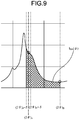
- FIG. 9 is an enlarged view of the part indicated by the dotted line in FIG. 4 .
- FIG. 9 illustrates calculation of a diffraction sensitivity I 002 ( ⁇ ) originating from the peak of the crystal face [002] of graphite.
- the shaded part is the diffraction sensitivity I 002 ( ⁇ ); the X-ray diffraction image (diffraction pattern) is integrated to calculate the diffraction sensitivity I 002 ( ⁇ ).
- the peak sensitivity I 002 ( ⁇ ) of the crystal face [002] of graphite can be calculated by Expression (6) below.
- I 002 ⁇ ⁇ 2 ⁇ A ⁇ ⁇ 2 ⁇ B I 2 ⁇ , ⁇ d 2 ⁇
- a value (2 ⁇ ) A + ⁇ obtained by adding the correction coefficient ⁇ to the angle (2 ⁇ ) A of the peak of the crystal face [002] of graphite may be a value larger than (2 ⁇ ) B .
- the peak sensitivity I 002 ( ⁇ ) of the crystal face [002] of graphite may be calculated by Expression (7) below with (2 ⁇ ) A - ⁇ as the lower limit and with (2 ⁇ ) A + ⁇ as the upper limit.
- I 002 ⁇ ⁇ 2 ⁇ A ⁇ ⁇ 2 ⁇ A + ⁇ I 2 ⁇ , ⁇ d 2 ⁇
- the diffraction image acquisition unit 10 illustrated in FIG. 2 can obtain an X-ray diffraction image containing diffraction at the crystal faces [002], [004], and [006] of graphite, and a diffraction sensitivity I 004 ( ⁇ ) and a diffraction sensitivity I 006 ( ⁇ ) of peaks originating from the crystal faces [004] and [006], respectively, of graphite are calculated in the same manner as the diffraction sensitivity I 002 ( ⁇ ) of the peak of the crystal face [002], and the sum of the diffraction sensitivities of the crystal faces of graphite is calculated as the diffraction sensitivity I c ( ⁇ ) from Expression (8) below.
- the diffraction sensitivity I 002 ( ⁇ ) at the crystal face [002] of graphite is the largest, and the diffraction sensitivity I 002 ( ⁇ ) may be regarded as the diffraction sensitivity I c ( ⁇ ).
- the orientation degree calculation unit 25 calculates the fiber orientation degree Sd( ⁇ ) by the method of Hermans from the diffraction sensitivity I c ( ⁇ ).
- the fiber orientation degree Sd( ⁇ ) is an indicator indicating a level of presence in each direction at which the discontinuous carbon fibers are oriented within the sample and is calculated using Expressions (2), (3), and (4) below by the method of Hermans in the present invention.
- FIG. 11 is a diagram illustrating calculation of the fiber orientation degree Sd( ⁇ ) from FIG. 10 .
- S 0 ⁇ ⁇ ⁇ / 2 ⁇ 90 ° + ⁇ / 2 + 90 ° I C ⁇ d ⁇
- S 1 ⁇ ⁇ ⁇ ⁇ / 2 ⁇ 90 ° + ⁇ / 2 + 90 ° I C ⁇ ⁇ cos 2 ⁇ d ⁇ 0
- ⁇ ⁇ - ⁇ 0 .
- Sd ⁇ 3 ⁇ S 1 ⁇ / S 0 ⁇ 1 / 2
- a maximum value Sd 0 of Sd( ⁇ ) determined by Expression (4) is a fiber orientation degree Sd 0 of the sample.
- Sd 0 max .
- FIG. 12 is a diagram of a relation between the azimuth angle ( ⁇ ) and the fiber orientation degree Sd( ⁇ ).
- the fiber orientation degree S( ⁇ ) of the discontinuous carbon fibers in the sample is measured by the process of a flowchart illustrated in FIG. 13 .
- the diffraction image acquisition unit 10 acquires an X-ray diffraction image of the sample (Step S1), and the peak angle calculation unit 21 calculates the angle (2 ⁇ ) A of the peak originating from the crystal face of graphite from the inflection point A of the integral value I(2 ⁇ ) obtained by integrating the X-ray diffraction image with respect to the azimuth angle ( ⁇ ) (Step S2).
- the crystal face of graphite for which the angle (2 ⁇ ) A is calculated may be [002], [004], and [006] or only [002].
- the correction coefficient calculation unit 22 calculates the correction coefficient ⁇ of the thickness of the sample (Step S3).
- the correction coefficient ⁇ may be calculated from Expression (2).
- the upper limit calculation unit 23 calculates the upper limit (2 ⁇ ) B of the peak of the crystal face of graphite from the inflection point B of the integral value I(2 ⁇ ) obtained by integrating the X-ray diffraction image with respect to the azimuth angle ( ⁇ ) (Step S4).
- the inflection point B is a next inflection point above the angle (2 ⁇ ) A of the peak originating from the crystal face of graphite.
- the diffraction sensitivity calculation unit 24 corrects the integrating range with the correction coefficient ⁇ calculated at Step S3 (Step S5) and integrates the X-ray diffraction image with the integrating range calculated at Step S5 to calculate the diffraction sensitivity I c ( ⁇ ) of the peak originating from the crystal face of graphite (Step S6).
- the integrating range is from (2 ⁇ ) A - ⁇ to (2 ⁇ ) B when (2 ⁇ ) B ⁇ (2 ⁇ ) A + ⁇ and from (2 ⁇ ) A - ⁇ to (2 ⁇ ) B when (2 ⁇ ) B ⁇ (2 ⁇ ) A + ⁇ .
- the orientation degree calculation unit 25 calculates the fiber orientation degree Sd( ⁇ ) by the method of Hermans from the diffraction sensitivity I c ( ⁇ ) (Step S7).
- the orientation degree calculation unit 25 outputs the maximum value Sd 0 of the fiber orientation degree Sd( ⁇ ) and the principal orientation angle ⁇ 0 to the controller 20.
- the controller 20 performs control to display the maximum value Sd 0 of the fiber orientation degree Sd( ⁇ ) and the principal orientation angle ⁇ 0 on the display unit 30 (Step S8).
- the present invention uses Expression (8) so that fiber orientation not only in the in-plane direction of the sample but also in the direction of the thickness t is taken into account for calculation of the fiber orientation degree Sd( ⁇ ). With this consideration, the fiber orientation degree Sd( ⁇ ) of a sample in which fiber orientation varies in the direction of the thickness t can be measured more accurately.
Landscapes
- Chemical & Material Sciences (AREA)
- Crystallography & Structural Chemistry (AREA)
- Physics & Mathematics (AREA)
- Health & Medical Sciences (AREA)
- Life Sciences & Earth Sciences (AREA)
- Analytical Chemistry (AREA)
- Biochemistry (AREA)
- General Health & Medical Sciences (AREA)
- General Physics & Mathematics (AREA)
- Immunology (AREA)
- Pathology (AREA)
- Analysing Materials By The Use Of Radiation (AREA)
Abstract
Description
- The present invention relates to a method for measuring a fiber orientation degree of a composite material containing discontinuous carbon fibers, a fiber orientation degree measurement apparatus, and a control program for a fiber orientation degree measurement apparatus.
- Caron fiber reinforced plastics (hereinafter, also called "CFRP") with improved strength by blending carbon fibers into plastics are being used for various uses. Information on a fiber orientation degree, that is, a level of presence in each direction at which carbon fibers present in CFRP are present, is important technical information for the properties of CFRP and determination of phenomena during molding.
- Examples of known means for measuring information on the distribution of carbon fibers in CFRP include X-ray computer tomography (CT), X-ray transmission imaging, and microscopic observation of polished surfaces; they have problems in that it takes time for pretreatment and measurement apparatuses are expensive.
- A method is developed, in which X-ray diffractometry is used, respective X-ray diffraction images are acquired for a sample for which the orientation degree is desired to be measured and a control sample in which carbon fibers are unidirectionally oriented, crystal orientation degrees from pieces of diffraction information of the respective samples are calculated, and a fiber orientation degree of the sample is calculated by removing the influence of a matrix resin in CFRP from a crystal orientation degree of the sample using a crystal orientation degree of the control sample (refer to
Patent Literature 1, for example). - Patent Literature 1: Japanese Patent Application Laid-open No.
2016-90259 - However, in
Patent Literature 1, the control sample is required to be prepared, and the orientation degree cannot simply be calculated. The crystal orientation degree calculated inPatent Literature 1 is a two-dimensional (in-plane) crystal orientation degree, in which fiber distribution in a thickness direction of the sample is not considered, and is difficult to use for a sample in which fiber orientation varies in the thickness direction. - The present invention has been made in view of the above, and an object thereof is to provide a method for measuring a fiber orientation degree, a fiber orientation degree measurement apparatus, and a control program for a fiber orientation degree measurement apparatus considering fiber orientation in a thickness direction simply and accurately.
- To solve the problem described above and to achieve the object, a method for measuring a fiber orientation degree according to the present invention includes: a diffraction image acquisition process of irradiating a sample formed of a composite material containing discontinuous carbon fibers with an X-ray to acquire an X-ray diffraction image; a peak angle calculation process of calculating an angle (2θ)A of a peak originating from a crystal face of graphite from an inflection point A of an integral value I(2θ) obtained by integrating the X-ray diffraction image with respect to an azimuth angle (φ); a correction coefficient calculation process of calculating a correction coefficient δ of a thickness of the sample; an upper limit calculation process of calculating an upper limit (2θ)B of the peak of the crystal face of graphite from an inflection point B of the integral value I(2θ); a diffraction sensitivity calculation process of calculating a diffraction sensitivity Ic(φ) of the peak originating from the crystal face of graphite by correcting an integrating range with the correction coefficient δ and integrating the X-ray diffraction image with respect to a diffraction angle (2θ); and an orientation degree calculation process of calculating a fiber orientation degree Sd(β) by the method of Hermans from the diffraction sensitivity Ic(φ).
- In the method for measuring a fiber orientation degree according to the present invention, the correction coefficient calculation process includes calculating the correction coefficient δ by Formula (1) below:

- In the method for measuring a fiber orientation degree according to the present invention, the diffraction sensitivity calculation process includes setting an angular integrating range to be from (2θ)A - δ to (2θ)A + δ when (2θ)A + δ > (2θ)B and setting the angular integrating range to be from (2θ)A - δ to (2θ)B when (2θ)A + δ ≤ (2θ)B.
- In the method for measuring a fiber orientation degree according to the present invention, the diffraction sensitivity calculated at the diffraction sensitivity calculation process is a sum of diffraction sensitivities of crystal faces [002], [004], and [006] of graphite.
- In the method for measuring a fiber orientation degree according to the present invention, the orientation degree calculation process includes calculating the fiber orientation degree Sd(β) by Expressions (2), (3), and (4) below:



- A fiber orientation degree measurement apparatus according to the present invention includes: a diffraction image acquisition unit configured to irradiate a sample formed of a composite material containing discontinuous carbon fibers with an X-ray to acquire an X-ray diffraction image; a peak angle calculation unit configured to calculate an angle (2θ)A of a peak originating from a crystal face of graphite from an inflection point A of an integral value I(2θ) obtained by integrating the X-ray diffraction image with respect to an azimuth angle (φ) ; a correction coefficient calculation unit configured to calculate a correction coefficient δ of a thickness of the sample; an upper limit calculation unit configured to calculate an upper limit (2θ)B of the peak of the crystal face of graphite from an inflection point B of the integral value I(2θ); a diffraction sensitivity calculation unit configured to calculate a diffraction sensitivity Ic(φ) of the peak originating from the crystal face of graphite by correcting an integrating range with the correction coefficient δ and integrating the X-ray diffraction image with respect to a diffraction angle (2θ); and an orientation degree calculation unit configured to calculate a fiber orientation degree Sd(β) by the method of Hermans from the diffraction sensitivity Ic(φ).
- A control program for a fiber orientation degree measurement apparatus according to the present invention executes: a diffraction image acquisition procedure of irradiating a sample formed of a composite material containing discontinuous carbon fibers with an X-ray to acquire an X-ray diffraction image; a peak angle calculation procedure of calculating an angle (2θ)A of a peak originating from a crystal face of graphite from an inflection point A of an integral value I(2θ) obtained by integrating the X-ray diffraction image with respect to an azimuth angle (φ); a correction coefficient calculation procedure of calculating a correction coefficient δ of a thickness of the sample; an upper limit calculation procedure of calculating an upper limit (2θ)B of the peak of the crystal face of graphite from an inflection point B of the integral value I(2θ); a diffraction sensitivity calculation procedure of calculating a diffraction sensitivity Ic(φ) of the peak originating from the crystal face of graphite by correcting an integrating range with the correction coefficient δ and integrating the X-ray diffraction image with respect to a diffraction angle (2θ); and an orientation degree calculation procedure of calculating a fiber orientation degree Sd(β) by the method of Hermans from the diffraction sensitivity Ic(φ).
- The method for measuring a fiber orientation degree, the fiber orientation degree measurement apparatus, and the control program for a fiber orientation degree measurement apparatus of the present invention do not need to produce a standard sample, also consider fiber orientation in the thickness direction of the sample, and can thus calculate the orientation degree of the carbon fibers in CFRP simply and more accurately.
-
-
FIG. 1 is a block diagram of a fiber orientation degree measurement apparatus according to an embodiment of the present invention. -
FIG. 2 is a diagram illustrating acquisition of an X-ray diffraction image according to the embodiment of the present invention. -
FIG. 3 is a diagram of an exemplary X-ray diffraction image according to the embodiment of the present invention. -
FIG. 4 is a diagram of an exemplary diffraction pattern in an azimuth angle (φ) of the X-ray diffraction image inFIG. 3 . -
FIG. 5 is a diagram of a relation between an integral value I(2θ) obtained by integrating the X-ray diffraction image inFIG. 3 with respect to the azimuth angle (φ) and a diffraction angle (2θ). -
FIG. 6 is an enlarged view of the part indicated by the dotted line inFIG. 5 . -
FIG. 7 is a diagram of a relation between a crystal face of graphite and a diffraction angle (2θ) of its peak. -
FIG. 8 is an enlarged view of the part indicated by the dotted line inFIG. 5 . -
FIG. 9 is an enlarged view of the part indicated by the dotted line inFIG. 4 . -
FIG. 10 is a diagram of a relation between the azimuth angle (φ) and a diffraction sensitivity Ic(φ) originating from the peak of the crystal face of graphite. -
FIG. 11 is a diagram illustrating calculation of a fiber orientation degree Sd(β) fromFIG. 10 . -
FIG. 12 is a diagram of a relation between the azimuth angle (φ) and the fiber orientation degree Sd(β). -
FIG. 13 is a flowchart illustrating measurement of the fiber orientation degree S(β) according to the embodiment of the present invention. - The following describes a method for measuring a fiber orientation degree, a fiber orientation degree measurement apparatus, and a control program for a fiber orientation degree measurement apparatus of the present invention with reference to the accompanying drawings.
-
FIG. 1 is a block diagram of a fiber orientationdegree measurement apparatus 100 according to an embodiment of the present invention. The fiber orientationdegree measurement apparatus 100 includes a diffractionimage acquisition unit 10, acontroller 20 controlling units, and adisplay unit 30 displaying a measured fiber orientation degree. - The diffraction
image acquisition unit 10 irradiates sample formed of a composite material containing discontinuous carbon fibers with an X-ray to acquire an X-ray diffraction image (a Debye ring). With measurement of a fiber orientation degree of the discontinuous carbon fibers in the composite material as an object, and with CFRP mainly containing discontinuous carbon fibers and a matrix resin as a sample, the fiber orientationdegree measurement apparatus 100 of the present invention acquires the X-ray diffraction image using a characteristic X-ray such as the Cu-Kα line. The fiber orientationdegree measurement apparatus 100 of the present invention is suitable for measurement of an orientation degree of the discontinuous carbon fibers in CFRP and can also be used for measurement of a fiber orientation degree in a mat formed of discontinuous carbon fibers containing no matrix resin. The discontinuous carbon fibers may be any of PAN-based and pitch-based carbon fibers. The matrix resin can be the sample of the present invention when any of a thermosetting resin, a thermoplastic resin, and a resin containing both a thermosetting resin and a thermoplastic resin is used so long as they are resins used for CFRP. - As illustrated in
FIG. 2 , the X-ray diffraction image can be acquired by irradiating the sample with an X-ray and receiving the X-ray reflected on a crystal face of the sample with a film (a camera) or an X-ray detector such as a flat panel detector (FPD). The X-ray diffraction image can be obtained by irradiating the sample (with a width of 5 to 10 mm, a length of 15 to 25 mm, and a thickness of 0.1 to 10 mm) with the characteristic X-ray (the Cu-Kα line) for 10 minutes.FIG. 3 is a diagram of an exemplary X-ray diffraction image according to the embodiment of the present invention.FIG. 3 is an X-ray diffraction image of CFRP containing nylon 6 (polyamide 6) as the matrix resin, in which a double ring (a Debye ring) originating from a polyamide crystal is observed (a shadow projected at the lower part of the X-ray diffraction image is a shadow of an apparatus applying the X-ray). - The
controller 20 has a peak angle calculation unit 21, a correctioncoefficient calculation unit 22, an upperlimit calculation unit 23, a diffractionsensitivity calculation unit 24, and an orientationdegree calculation unit 25. Thecontroller 20 is implemented by using a central processing unit (CPU) executing various kinds of processing programs, a read only memory (ROM) storing therein the various kinds of processing programs and the like in advance, and a random access memory (RAM) storing therein an arithmetic orientation degree of each processing and the like. As thecontroller 20, a general-purpose computer such as a work station or a personal computer can be used. - The peak angle calculation unit 21 extracts a diffraction pattern with a certain azimuth angle (φ) from the X-ray diffraction image acquired by the diffraction
image acquisition unit 10 and calculates an angle (2θ)A of a peak originating from a crystal face of graphite from an inflection point of an integral value of the diffraction pattern. - As illustrated in
FIG. 2 , the X-ray diffraction image indicates a relation between a diffraction angle (2θ) and a diffraction sensitivity I(2θ, φ) of the X-ray reflected on the crystal face of the sample, which is, for example, the polyamide crystal or the crystal face [002], [004], [006], or the like of graphite, and the azimuth angle (φ). The peak angle calculation unit 21 calculates the angle (2θ)A of the peak originating from the crystal face of graphite from a diffraction pattern in a direction of the azimuth angle (φ), that is, a diffraction pattern in a circumferential direction from the center of the X-ray diffraction image in the direction of the azimuth angle (φ). The following describes calculation of the angle (2θ)A of the peak originating from the crystal face [002], which gives the highest diffraction sensitivity. -
FIG. 4 is a diagram of an exemplary diffraction pattern at the azimuth angle (φ) of the X-ray diffraction image inFIG. 3 . In the diffraction pattern inFIG. 4 , peaks with a diffraction angle (2θ) of around 20° and 24.5° originate from the polyamide crystal, whereas a peak of a shoulder of the peak of polyamide around 24.5° is a peak originating from the crystal face [002] of graphite. - The peak angle calculation unit 21 integrates the X-ray diffraction image in
FIG. 3 in the direction of the azimuth angle (φ) according to Expression (5) below to calculate the angle (2θ)A of the peak of the crystal face [002] of graphite from the inflection point.
-
FIG. 5 is a diagram of a relation between an integral value I(2θ) obtained by integrating the X-ray diffraction image inFIG. 3 with respect to the azimuth angle (φ) and the diffraction angle (2θ).FIG. 6 is an enlarged view of the part indicated by the dotted line inFIG. 5 (near the diffraction angle of the crystal face [002] of graphite). An inflection point A appearing near the diffraction angle 2θ of the crystal face [002] of graphite of the integral value I(2θ) illustrated inFIG. 5 is the angle (2θ)A of the peak of the crystal face [002] of graphite. - The peak angle (2θ)A originating from the [002] face can be determined by referring to the diffraction angle 2θ (25.9 to 26.6°) of the crystal face [002] of general graphite illustrated in
FIG. 7 and calculating a differential coefficient from above the diffraction angle 2θ (25.9 to 26.6°) of the crystal face [002]. Although the diffraction angle 2θ of the crystal face of graphite varies by conditions when a graphite crystal is generated, the diffraction angle 2θ of the crystal face [002] of the discontinuous carbon fibers used as the sample is considered to be near the diffraction angle 2θ (25.9 to 26.6°) of the crystal face [002] illustrated inFIG. 7 , and the inflection point A can be determined by calculating the differential coefficient near the diffraction angle 2θ (25.9 to 26.6°) of the crystal face [002]. - The correction
coefficient calculation unit 22 calculates a correction coefficient δ of a thickness t (mm) of the sample. The correction coefficient δ can be calculated by Expression (1) below.
- The diffraction angle (2θ) on the horizontal axis of the diffraction pattern in
FIG. 4 includes information in a direction of the thickness t of the sample, and the peak angle (2θ)A is corrected with the correction coefficient δ. With this correction, a fiber orientation degree with fiber orientation not only in the two-dimensional (in-plane) direction of the sample but also in the thickness direction taken into account can be measured. - The upper
limit calculation unit 23 calculates an upper limit (2θ)B of the peak originating from the crystal face of graphite from an angle (2θ)B of an inflection point B of the integral value I(2θ) obtained by integrating the X-ray diffraction image with respect to the azimuth angle (φ) . The upper limit (2θ)B of the peak is an upper limit of an integrating range when the diffractionsensitivity calculation unit 24 described below integrates the diffraction sensitivity 1(28, φ) with respect to the diffraction angle (2θ) to calculate a diffraction sensitivity Ic(φ) of the peak of the crystal face of graphite. -
FIG. 8 is an enlarged view of the part indicated by the dotted line inFIG. 5 (near the angle (2θ)A of the peak of the crystal face [002] of graphite). The inflection point B is determined by calculating a differential coefficient upward from the angle (2θ)A of the peak of the crystal face [002] of graphite. The angle (2θ)B of the next inflection point B above the angle (2θ)A of the peak of the crystal face [002] of graphite (the inflection point following the inflection point A; the differential coefficient of the inflection point B is normally zero) is the upper limit of the integrating range when the diffraction sensitivity Ic(φ) is calculated. - The diffraction
sensitivity calculation unit 24 calculates the diffraction sensitivity Ic(φ) of the peak originating from the crystal face of graphite by correcting the integrating range with the correction coefficient δ calculated by the correctioncoefficient calculation unit 22 and integrating the X-ray diffraction image with respect to the diffraction angle (2θ).FIG. 9 is an enlarged view of the part indicated by the dotted line inFIG. 4 .FIG. 9 illustrates calculation of a diffraction sensitivity I002(φ) originating from the peak of the crystal face [002] of graphite. InFIG. 9 , the shaded part is the diffraction sensitivity I002(φ); the X-ray diffraction image (diffraction pattern) is integrated to calculate the diffraction sensitivity I002(φ). - With a value (2θ)A - δ obtained by subtracting the correction coefficient δ from the angle (2θ)A of the peak of the crystal face [002] of graphite as the lower limit of the integrating range and with (2θ)B calculated by the upper
limit calculation unit 23 as the upper limit, the peak sensitivity I002(φ) of the crystal face [002] of graphite can be calculated by Expression (6) below.
- Depending on the correction coefficient δ, a value (2θ)A + δ obtained by adding the correction coefficient δ to the angle (2θ)A of the peak of the crystal face [002] of graphite may be a value larger than (2θ)B.
In such a case, the peak sensitivity I002(φ) of the crystal face [002] of graphite may be calculated by Expression (7) below with (2θ)A - δ as the lower limit and with (2θ)A + δ as the upper limit.
- The diffraction
image acquisition unit 10 illustrated inFIG. 2 can obtain an X-ray diffraction image containing diffraction at the crystal faces [002], [004], and [006] of graphite, and a diffraction sensitivity I004(φ) and a diffraction sensitivity I006(φ) of peaks originating from the crystal faces [004] and [006], respectively, of graphite are calculated in the same manner as the diffraction sensitivity I002(φ) of the peak of the crystal face [002], and the sum of the diffraction sensitivities of the crystal faces of graphite is calculated as the diffraction sensitivity Ic(φ) from Expression (8) below.
- The orientation
degree calculation unit 25 calculates the fiber orientation degree Sd(β) by the method of Hermans from the diffraction sensitivity Ic(φ).FIG. 10 is a diagram of a relation between the azimuth angle (φ) and the diffraction sensitivity Ic(φ) originating from the peak of the crystal face of graphite, in which the diffraction sensitivity Ic(φ) with an azimuth angle (φ) of φ = 1 to 360 is illustrated (for φ = 140 to 212°, the diffraction sensitivity Ic(φ) is not calculated under the influence of the shadow of the apparatus). - The fiber orientation degree Sd(β) is an indicator indicating a level of presence in each direction at which the discontinuous carbon fibers are oriented within the sample and is calculated using Expressions (2), (3), and (4) below by the method of Hermans in the present invention.
FIG. 11 is a diagram illustrating calculation of the fiber orientation degree Sd(β) fromFIG. 10 .


- As shown in Expression (9) below, a maximum value Sd0 of Sd(β) determined by Expression (4) is a fiber orientation degree Sd0 of the sample.

- As shown in Expression (10) below, β when Sd(β) is the maximum value Sd0 is β0.

- The crystal faces [002] and the like of graphite deviate from the direction of a principal axis of the carbon fibers by 90°, and a principal orientation angle α0 of the discontinuous carbon fibers is as Expression (11) below.

-
FIG. 12 is a diagram of a relation between the azimuth angle (φ) and the fiber orientation degree Sd(β). The fiber orientation degree Sd(β) is illustrated together with the diffraction sensitivity I002(φ), in which the data of the fiber orientation degree Sd(β) and the diffraction sensitivity I002(φ) in φ = 90 to 270° is illustrated as rotational symmetry of the data in 0 to 90° and 270 to 360° for the sake of simplicity. It can be seen from the fiber orientation degree Sd(β) inFIG. 12 that the maximum value Sd0 is given by β0 = 358°, whereas the principal orientation angle α0 is 88°. - The fiber orientation degree S(β) of the discontinuous carbon fibers in the sample is measured by the process of a flowchart illustrated in
FIG. 13 . - First, the diffraction
image acquisition unit 10 acquires an X-ray diffraction image of the sample (Step S1), and the peak angle calculation unit 21 calculates the angle (2θ)A of the peak originating from the crystal face of graphite from the inflection point A of the integral value I(2θ) obtained by integrating the X-ray diffraction image with respect to the azimuth angle (φ) (Step S2). The crystal face of graphite for which the angle (2θ)A is calculated may be [002], [004], and [006] or only [002]. - Subsequently, the correction
coefficient calculation unit 22 calculates the correction coefficient δ of the thickness of the sample (Step S3). The correction coefficient δ may be calculated from Expression (2). - Subsequently, the upper
limit calculation unit 23 calculates the upper limit (2θ)B of the peak of the crystal face of graphite from the inflection point B of the integral value I(2θ) obtained by integrating the X-ray diffraction image with respect to the azimuth angle (φ) (Step S4). The inflection point B is a next inflection point above the angle (2θ)A of the peak originating from the crystal face of graphite. - After the upper limit (2θ)B of the peak is calculated (Step S4), the diffraction
sensitivity calculation unit 24 corrects the integrating range with the correction coefficient δ calculated at Step S3 (Step S5) and integrates the X-ray diffraction image with the integrating range calculated at Step S5 to calculate the diffraction sensitivity Ic(φ) of the peak originating from the crystal face of graphite (Step S6). The integrating range is from (2θ)A - δ to (2θ)B when (2θ)B ≥ (2θ)A + δ and from (2θ)A - δ to (2θ)B when (2θ)B < (2θ)A + δ. - After the diffraction sensitivity Ic(φ) is calculated (Step S6), the orientation
degree calculation unit 25 calculates the fiber orientation degree Sd(β) by the method of Hermans from the diffraction sensitivity Ic(φ) (Step S7). The orientationdegree calculation unit 25 outputs the maximum value Sd0 of the fiber orientation degree Sd(β) and the principal orientation angle α0 to thecontroller 20. - The
controller 20 performs control to display the maximum value Sd0 of the fiber orientation degree Sd(β) and the principal orientation angle α0 on the display unit 30 (Step S8). - The present invention uses Expression (8) so that fiber orientation not only in the in-plane direction of the sample but also in the direction of the thickness t is taken into account for calculation of the fiber orientation degree Sd(β). With this consideration, the fiber orientation degree Sd(β) of a sample in which fiber orientation varies in the direction of the thickness t can be measured more accurately.
-
- 10
- Diffraction image acquisition unit
- 20
- Controller
- 21
- Peak angle calculation unit
- 22
- Correction coefficient calculation unit
- 23
- Upper limit calculation unit
- 24
- Diffraction sensitivity calculation unit
- 25
- Orientation degree calculation unit
- 30
- Display unit
- 100
- Fiber orientation degree measurement apparatus
Claims (7)
- A method for measuring a fiber orientation degree comprising:a diffraction image acquisition process of irradiating a sample formed of a composite material containing discontinuous carbon fibers with an X-ray to acquire an X-ray diffraction image;a peak angle calculation process of calculating an angle (2θ)A of a peak originating from a crystal face of graphite from an inflection point A of an integral value I(2θ) obtained by integrating the X-ray diffraction image with respect to an azimuth angle (φ) ;a correction coefficient calculation process of calculating a correction coefficient δ of a thickness of the sample;an upper limit calculation process of calculating an upper limit (2θ)B of the peak of the crystal face of graphite from an inflection point B of the integral value I(2θ);a diffraction sensitivity calculation process of calculating a diffraction sensitivity Ic(φ) of the peak originating from the crystal face of graphite by correcting an integrating range with the correction coefficient δ and integrating the X-ray diffraction image with respect to a diffraction angle (2θ); andan orientation degree calculation process of calculating a fiber orientation degree Sd(β) by the method of Hermans from the diffraction sensitivity Ic(φ).
- The method for measuring a fiber orientation degree according to claim 1, wherein the correction coefficient calculation process includes calculating the correction coefficient δ by Formula (1) below:

- The method for measuring a fiber orientation degree according to claim 1 or 2, wherein the diffraction sensitivity calculation process includes setting an angular integrating range to be from (2θ)A - δ to (2θ)A + δ when (2θ)A + δ > (2θ)B and setting the angular integrating range to be from (2θ)A - δ to (2θ)B when (2θ)A + δ ≤ (2θ)B.
- The method for measuring a fiber orientation degree according to any one of claims 1 to 3, wherein the diffraction sensitivity calculated at the diffraction sensitivity calculation process is a sum of diffraction sensitivities of crystal faces [002], [004], and [006] of graphite.
- The method for measuring a fiber orientation degree according to any one of claims 1 to 4, wherein the orientation degree calculation process includes calculating the fiber orientation degree Sd(β) by Expressions (2), (3), and (4) below:


- A fiber orientation degree measurement apparatus comprising:a diffraction image acquisition unit configured to irradiate a sample formed of a composite material containing discontinuous carbon fibers with an X-ray to acquire an X-ray diffraction image;a peak angle calculation unit configured to calculate an angle (2θ)A of a peak originating from a crystal face of graphite from an inflection point A of an integral value I(2θ) obtained by integrating the X-ray diffraction image with respect to an azimuth angle (φ);a correction coefficient calculation unit configured to calculate a correction coefficient δ of a thickness of the sample;an upper limit calculation unit configured to calculate an upper limit (2θ)B of the peak of the crystal face of graphite from an inflection point B of the integral value I(2θ);a diffraction sensitivity calculation unit configured to calculate a diffraction sensitivity Ic(φ) of the peak originating from the crystal face of graphite by correcting an integrating range with the correction coefficient δ and integrating the X-ray diffraction image with respect to a diffraction angle (2θ); andan orientation degree calculation unit configured to calculate a fiber orientation degree Sd(β) by the method of Hermans from the diffraction sensitivity Ic(φ).
- A control program for a fiber orientation degree measurement apparatus executing:a diffraction image acquisition procedure of irradiating a sample formed of a composite material containing discontinuous carbon fibers with an X-ray to acquire an X-ray diffraction image;a peak angle calculation procedure of calculating an angle (2θ)A of a peak originating from a crystal face of graphite from an inflection point A of an integral value I(2θ) obtained by integrating the X-ray diffraction image with respect to an azimuth angle (φ) ;a correction coefficient calculation procedure of calculating a correction coefficient δ of a thickness of the sample;an upper limit calculation procedure of calculating an upper limit (2θ)B of the peak of the crystal face of graphite from an inflection point B of the integral value I(2θ) ;a diffraction sensitivity calculation procedure of calculating a diffraction sensitivity Ic(φ) of the peak originating from the crystal face of graphite by correcting an integrating range with the correction coefficient δ and integrating the X-ray diffraction image with respect to a diffraction angle (2θ); andan orientation degree calculation procedure of calculating a fiber orientation degree Sd(β) by the method of Hermans from the diffraction sensitivity Ic(φ).
Applications Claiming Priority (2)
| Application Number | Priority Date | Filing Date | Title |
|---|---|---|---|
| JP2017193769A JP6860463B2 (en) | 2017-10-03 | 2017-10-03 | Fiber orientation measuring method, fiber orientation measuring device, and control program of fiber orientation measuring device |
| PCT/JP2018/036953 WO2019069956A1 (en) | 2017-10-03 | 2018-10-02 | Method for measuring degree of orientation of fibers, device for measuring degree of orientation of fibers, and program for controlling device for measuring degree of orientation of fibers |
Publications (3)
| Publication Number | Publication Date |
|---|---|
| EP3693727A1 true EP3693727A1 (en) | 2020-08-12 |
| EP3693727A4 EP3693727A4 (en) | 2021-07-21 |
| EP3693727B1 EP3693727B1 (en) | 2023-08-23 |
Family
ID=65995209
Family Applications (1)
| Application Number | Title | Priority Date | Filing Date |
|---|---|---|---|
| EP18864002.3A Active EP3693727B1 (en) | 2017-10-03 | 2018-10-02 | Method for measuring degree of orientation of fibers, device for measuring degree of orientation of fibers, and program for controlling device for measuring degree of orientation of fibers |
Country Status (5)
| Country | Link |
|---|---|
| US (1) | US11360035B2 (en) |
| EP (1) | EP3693727B1 (en) |
| JP (1) | JP6860463B2 (en) |
| KR (1) | KR102556672B1 (en) |
| WO (1) | WO2019069956A1 (en) |
Families Citing this family (3)
| Publication number | Priority date | Publication date | Assignee | Title |
|---|---|---|---|---|
| JP7460180B2 (en) * | 2019-08-30 | 2024-04-02 | 国立研究開発法人産業技術総合研究所 | Orientation distribution calculation method, orientation distribution analysis device, and orientation distribution analysis program |
| KR102926510B1 (en) * | 2020-05-26 | 2026-02-10 | 삼성전자주식회사 | Calculation method of graphene layer and measurement method of silicon carbide content using XPS |
| CN116735633B (en) * | 2023-06-13 | 2026-05-26 | 中国科学院山西煤炭化学研究所 | X-ray powder diffraction method for determining the macroscopic composition and microstructure of carbon materials |
Family Cites Families (22)
| Publication number | Priority date | Publication date | Assignee | Title |
|---|---|---|---|---|
| JP3138618B2 (en) * | 1995-07-31 | 2001-02-26 | 三菱電機株式会社 | Vehicle distance measuring device |
| JPH0989816A (en) * | 1995-09-21 | 1997-04-04 | Shimadzu Corp | X-ray diffraction data processing method |
| US6141480A (en) * | 1998-10-29 | 2000-10-31 | The United States Of America As Represented By The Secretary Of The Navy | Technique for location of embedded fiber optic sensors |
| JP3887588B2 (en) * | 2002-08-30 | 2007-02-28 | 株式会社リガク | Stress measurement method by X-ray diffraction |
| CN201352204Y (en) * | 2009-01-22 | 2009-11-25 | 北京普析通用仪器有限责任公司 | Special sample table for measuring fiber orientation by using X-ray diffraction instrument |
| US8748817B2 (en) * | 2010-07-27 | 2014-06-10 | Vineet Kumar | Orientation imaging using wide angle convergent beam diffraction in transmission electron microscopy |
| GB201218720D0 (en) * | 2012-10-18 | 2012-12-05 | Airbus Operations Ltd | Fibre orientation optimisation |
| JP6118698B2 (en) * | 2013-09-30 | 2017-04-19 | 株式会社Ihi | Image analysis apparatus and program |
| USRE48612E1 (en) * | 2013-10-31 | 2021-06-29 | Sigray, Inc. | X-ray interferometric imaging system |
| JP6242185B2 (en) * | 2013-11-22 | 2017-12-06 | 株式会社リガク | Correction information generation method and correction information generation apparatus |
| DE102014100419A1 (en) * | 2014-01-15 | 2015-07-16 | Volume Graphics Gmbh | Apparatus and method for inspecting components with fiber composite or fiber composite fabrics |
| JP2016090259A (en) * | 2014-10-30 | 2016-05-23 | 三菱レイヨン株式会社 | Method, program, device and system for calculating degree of fiber orientation |
| JP5783318B1 (en) * | 2014-11-28 | 2015-09-24 | Jfeスチール株式会社 | Trace carbon quantitative analyzer and trace carbon quantitative analysis method |
| CZ2015623A3 (en) * | 2015-09-15 | 2016-10-05 | Advacam S.R.O. | Method of detecting defects in materials of internal directional structure and apparatus for making the same |
| WO2017108689A1 (en) * | 2015-12-23 | 2017-06-29 | Lm Wp Patent Holding A/S | Methods for detecting a fibre misalignment in an elongated structure, related apparatuses |
| EP3258253A1 (en) * | 2016-06-13 | 2017-12-20 | Technische Universität München | X-ray tensor tomography system |
| US11275036B2 (en) * | 2016-12-09 | 2022-03-15 | Nanyang Technological University | Non-destructive testing methods and apparatus |
| JP6943090B2 (en) * | 2017-09-05 | 2021-09-29 | 株式会社島津製作所 | X-ray imaging device |
| US10613042B2 (en) * | 2017-09-28 | 2020-04-07 | International Business Machines Corporation | Measuring and analyzing residual stresses and their gradients in materials using high resolution grazing incidence X-ray diffraction |
| EP3506332B1 (en) * | 2017-12-29 | 2020-12-23 | Jeol Ltd. | Scanning electron microscope and analysis method |
| WO2019161497A1 (en) * | 2018-02-22 | 2019-08-29 | Proto Patents Ltd. | Carbon fiber window for x-ray diffractometer |
| WO2020032922A1 (en) * | 2018-08-07 | 2020-02-13 | Siemens Medical Solutions Usa, Inc. | Multi-modal compton and single photon emission computed tomography medical imaging system |
-
2017
- 2017-10-03 JP JP2017193769A patent/JP6860463B2/en active Active
-
2018
- 2018-10-02 KR KR1020207012120A patent/KR102556672B1/en active Active
- 2018-10-02 EP EP18864002.3A patent/EP3693727B1/en active Active
- 2018-10-02 WO PCT/JP2018/036953 patent/WO2019069956A1/en not_active Ceased
- 2018-10-02 US US16/652,906 patent/US11360035B2/en not_active Expired - Fee Related
Also Published As
| Publication number | Publication date |
|---|---|
| WO2019069956A1 (en) | 2019-04-11 |
| KR102556672B1 (en) | 2023-07-18 |
| EP3693727B1 (en) | 2023-08-23 |
| US20200300788A1 (en) | 2020-09-24 |
| JP2019066389A (en) | 2019-04-25 |
| US11360035B2 (en) | 2022-06-14 |
| KR20210071871A (en) | 2021-06-16 |
| EP3693727A4 (en) | 2021-07-21 |
| JP6860463B2 (en) | 2021-04-14 |
Similar Documents
| Publication | Publication Date | Title |
|---|---|---|
| EP3693727B1 (en) | Method for measuring degree of orientation of fibers, device for measuring degree of orientation of fibers, and program for controlling device for measuring degree of orientation of fibers | |
| JP7067221B2 (en) | X-ray system | |
| US10697902B2 (en) | X-ray tensor tomography system | |
| Bernasconi et al. | Analysis of fibre orientation distribution in short fibre reinforced polymers: A comparison between optical and tomographic methods | |
| Lee et al. | Digital volume correlation technique for characterizing subsurface deformation behavior of a laminated composite | |
| EP3367086A1 (en) | X-ray device, data processing device, and data processing method | |
| US8184766B2 (en) | X-ray computer tomograph and method for investigating an object by means of X-ray computer tomography | |
| US20100074414A1 (en) | Dose measuring method, and phantom and X-ray radiographic device used in dose measuring method | |
| Lecomte-Grosbras et al. | Three-dimensional investigation of free-edge effects in laminate composites using x-ray tomography and digital volume correlation | |
| Nervo et al. | Comparison between a near-field and a far-field indexing approach for characterization of a polycrystalline sample volume containing more than 1500 grains | |
| CN205449833U (en) | Accurate detectable material's of digit ray transillumination technique defect and device of thickness | |
| CN111664978B (en) | Residual stress characterization method for spherical special-shaped part | |
| CN110726386B (en) | Measuring method of full stress strain tensor of material based on Laue photographic method | |
| Peng et al. | Long-term Inter-protocol kV CBCT image quality assessment for a ring-gantry linac via automated QA approach | |
| Dyussambayev et al. | TITAN neutron imaging facility performance | |
| Polak et al. | Automated x‐ray/light field congruence using the LINAC EPID panel | |
| WO2013183470A1 (en) | X-ray apparatus and method of measuring x-rays | |
| JP7306528B2 (en) | Control device, display method and inspection method | |
| Wilhelmsson et al. | X-ray tomography data of compression tested unidirectional fibre composites with different off-axis angles | |
| Sun et al. | Monochromatic X-ray imaging using a combination of doubly curved crystal and polycapillary X-ray lens | |
| Amatullah et al. | Automatic measurement of slice thickness in CT images of a Siemens phantom | |
| Hunt et al. | Variation in isocentre location of an Elekta Unity MR-linac through full gantry rotation | |
| Zhi-Qiang et al. | Polynomial curve fitting method for refraction-angle extraction in diffraction enhanced imaging | |
| Sulyanov et al. | A simple approach to determine the polarization coefficient at synchrotron radiation stations | |
| CN107036563B (en) | Determine the method and ct apparatus of projection angular accuracy and projected angle |
Legal Events
| Date | Code | Title | Description |
|---|---|---|---|
| STAA | Information on the status of an ep patent application or granted ep patent |
Free format text: STATUS: THE INTERNATIONAL PUBLICATION HAS BEEN MADE |
|
| PUAI | Public reference made under article 153(3) epc to a published international application that has entered the european phase |
Free format text: ORIGINAL CODE: 0009012 |
|
| STAA | Information on the status of an ep patent application or granted ep patent |
Free format text: STATUS: REQUEST FOR EXAMINATION WAS MADE |
|
| 17P | Request for examination filed |
Effective date: 20200330 |
|
| AK | Designated contracting states |
Kind code of ref document: A1 Designated state(s): AL AT BE BG CH CY CZ DE DK EE ES FI FR GB GR HR HU IE IS IT LI LT LU LV MC MK MT NL NO PL PT RO RS SE SI SK SM TR |
|
| AX | Request for extension of the european patent |
Extension state: BA ME |
|
| RAP1 | Party data changed (applicant data changed or rights of an application transferred) |
Owner name: KYOWA INDUSTRIAL CO., LTD. Owner name: TORAY INDUSTRIES, INC. Owner name: NATIONAL UNIVERSITY CORPORATION TOKAI NATIONAL HIGHER EDUCATION AND RESEARCH SYSTEM |
|
| DAV | Request for validation of the european patent (deleted) | ||
| DAX | Request for extension of the european patent (deleted) | ||
| A4 | Supplementary search report drawn up and despatched |
Effective date: 20210623 |
|
| RIC1 | Information provided on ipc code assigned before grant |
Ipc: G01N 23/2055 20180101AFI20210617BHEP Ipc: G01N 23/207 20180101ALI20210617BHEP |
|
| RAP1 | Party data changed (applicant data changed or rights of an application transferred) |
Owner name: TORAY INDUSTRIES, INC. Owner name: NATIONAL UNIVERSITY CORPORATION TOKAI NATIONAL HIGHER EDUCATION AND RESEARCH SYSTEM |
|
| GRAP | Despatch of communication of intention to grant a patent |
Free format text: ORIGINAL CODE: EPIDOSNIGR1 |
|
| STAA | Information on the status of an ep patent application or granted ep patent |
Free format text: STATUS: GRANT OF PATENT IS INTENDED |
|
| INTG | Intention to grant announced |
Effective date: 20230310 |
|
| GRAS | Grant fee paid |
Free format text: ORIGINAL CODE: EPIDOSNIGR3 |
|
| GRAA | (expected) grant |
Free format text: ORIGINAL CODE: 0009210 |
|
| STAA | Information on the status of an ep patent application or granted ep patent |
Free format text: STATUS: THE PATENT HAS BEEN GRANTED |
|
| AK | Designated contracting states |
Kind code of ref document: B1 Designated state(s): AL AT BE BG CH CY CZ DE DK EE ES FI FR GB GR HR HU IE IS IT LI LT LU LV MC MK MT NL NO PL PT RO RS SE SI SK SM TR |
|
| REG | Reference to a national code |
Ref country code: GB Ref legal event code: FG4D |
|
| REG | Reference to a national code |
Ref country code: CH Ref legal event code: EP |
|
| P01 | Opt-out of the competence of the unified patent court (upc) registered |
Effective date: 20230731 |
|
| REG | Reference to a national code |
Ref country code: IE Ref legal event code: FG4D |
|
| REG | Reference to a national code |
Ref country code: DE Ref legal event code: R096 Ref document number: 602018056138 Country of ref document: DE |
|
| REG | Reference to a national code |
Ref country code: LT Ref legal event code: MG9D |
|
| REG | Reference to a national code |
Ref country code: NL Ref legal event code: MP Effective date: 20230823 |
|
| REG | Reference to a national code |
Ref country code: AT Ref legal event code: MK05 Ref document number: 1603161 Country of ref document: AT Kind code of ref document: T Effective date: 20230823 |
|
| PG25 | Lapsed in a contracting state [announced via postgrant information from national office to epo] |
Ref country code: GR Free format text: LAPSE BECAUSE OF FAILURE TO SUBMIT A TRANSLATION OF THE DESCRIPTION OR TO PAY THE FEE WITHIN THE PRESCRIBED TIME-LIMIT Effective date: 20231124 |
|
| PG25 | Lapsed in a contracting state [announced via postgrant information from national office to epo] |
Ref country code: IS Free format text: LAPSE BECAUSE OF FAILURE TO SUBMIT A TRANSLATION OF THE DESCRIPTION OR TO PAY THE FEE WITHIN THE PRESCRIBED TIME-LIMIT Effective date: 20231223 |
|
| PG25 | Lapsed in a contracting state [announced via postgrant information from national office to epo] |
Ref country code: SE Free format text: LAPSE BECAUSE OF FAILURE TO SUBMIT A TRANSLATION OF THE DESCRIPTION OR TO PAY THE FEE WITHIN THE PRESCRIBED TIME-LIMIT Effective date: 20230823 Ref country code: RS Free format text: LAPSE BECAUSE OF FAILURE TO SUBMIT A TRANSLATION OF THE DESCRIPTION OR TO PAY THE FEE WITHIN THE PRESCRIBED TIME-LIMIT Effective date: 20230823 Ref country code: PT Free format text: LAPSE BECAUSE OF FAILURE TO SUBMIT A TRANSLATION OF THE DESCRIPTION OR TO PAY THE FEE WITHIN THE PRESCRIBED TIME-LIMIT Effective date: 20231226 Ref country code: NO Free format text: LAPSE BECAUSE OF FAILURE TO SUBMIT A TRANSLATION OF THE DESCRIPTION OR TO PAY THE FEE WITHIN THE PRESCRIBED TIME-LIMIT Effective date: 20231123 Ref country code: NL Free format text: LAPSE BECAUSE OF FAILURE TO SUBMIT A TRANSLATION OF THE DESCRIPTION OR TO PAY THE FEE WITHIN THE PRESCRIBED TIME-LIMIT Effective date: 20230823 Ref country code: LV Free format text: LAPSE BECAUSE OF FAILURE TO SUBMIT A TRANSLATION OF THE DESCRIPTION OR TO PAY THE FEE WITHIN THE PRESCRIBED TIME-LIMIT Effective date: 20230823 Ref country code: LT Free format text: LAPSE BECAUSE OF FAILURE TO SUBMIT A TRANSLATION OF THE DESCRIPTION OR TO PAY THE FEE WITHIN THE PRESCRIBED TIME-LIMIT Effective date: 20230823 Ref country code: IS Free format text: LAPSE BECAUSE OF FAILURE TO SUBMIT A TRANSLATION OF THE DESCRIPTION OR TO PAY THE FEE WITHIN THE PRESCRIBED TIME-LIMIT Effective date: 20231223 Ref country code: HR Free format text: LAPSE BECAUSE OF FAILURE TO SUBMIT A TRANSLATION OF THE DESCRIPTION OR TO PAY THE FEE WITHIN THE PRESCRIBED TIME-LIMIT Effective date: 20230823 Ref country code: GR Free format text: LAPSE BECAUSE OF FAILURE TO SUBMIT A TRANSLATION OF THE DESCRIPTION OR TO PAY THE FEE WITHIN THE PRESCRIBED TIME-LIMIT Effective date: 20231124 Ref country code: FI Free format text: LAPSE BECAUSE OF FAILURE TO SUBMIT A TRANSLATION OF THE DESCRIPTION OR TO PAY THE FEE WITHIN THE PRESCRIBED TIME-LIMIT Effective date: 20230823 Ref country code: AT Free format text: LAPSE BECAUSE OF FAILURE TO SUBMIT A TRANSLATION OF THE DESCRIPTION OR TO PAY THE FEE WITHIN THE PRESCRIBED TIME-LIMIT Effective date: 20230823 |
|
| PG25 | Lapsed in a contracting state [announced via postgrant information from national office to epo] |
Ref country code: PL Free format text: LAPSE BECAUSE OF FAILURE TO SUBMIT A TRANSLATION OF THE DESCRIPTION OR TO PAY THE FEE WITHIN THE PRESCRIBED TIME-LIMIT Effective date: 20230823 |
|
| PG25 | Lapsed in a contracting state [announced via postgrant information from national office to epo] |
Ref country code: ES Free format text: LAPSE BECAUSE OF FAILURE TO SUBMIT A TRANSLATION OF THE DESCRIPTION OR TO PAY THE FEE WITHIN THE PRESCRIBED TIME-LIMIT Effective date: 20230823 |
|
| PG25 | Lapsed in a contracting state [announced via postgrant information from national office to epo] |
Ref country code: SM Free format text: LAPSE BECAUSE OF FAILURE TO SUBMIT A TRANSLATION OF THE DESCRIPTION OR TO PAY THE FEE WITHIN THE PRESCRIBED TIME-LIMIT Effective date: 20230823 Ref country code: RO Free format text: LAPSE BECAUSE OF FAILURE TO SUBMIT A TRANSLATION OF THE DESCRIPTION OR TO PAY THE FEE WITHIN THE PRESCRIBED TIME-LIMIT Effective date: 20230823 Ref country code: ES Free format text: LAPSE BECAUSE OF FAILURE TO SUBMIT A TRANSLATION OF THE DESCRIPTION OR TO PAY THE FEE WITHIN THE PRESCRIBED TIME-LIMIT Effective date: 20230823 Ref country code: EE Free format text: LAPSE BECAUSE OF FAILURE TO SUBMIT A TRANSLATION OF THE DESCRIPTION OR TO PAY THE FEE WITHIN THE PRESCRIBED TIME-LIMIT Effective date: 20230823 Ref country code: DK Free format text: LAPSE BECAUSE OF FAILURE TO SUBMIT A TRANSLATION OF THE DESCRIPTION OR TO PAY THE FEE WITHIN THE PRESCRIBED TIME-LIMIT Effective date: 20230823 Ref country code: CZ Free format text: LAPSE BECAUSE OF FAILURE TO SUBMIT A TRANSLATION OF THE DESCRIPTION OR TO PAY THE FEE WITHIN THE PRESCRIBED TIME-LIMIT Effective date: 20230823 Ref country code: SK Free format text: LAPSE BECAUSE OF FAILURE TO SUBMIT A TRANSLATION OF THE DESCRIPTION OR TO PAY THE FEE WITHIN THE PRESCRIBED TIME-LIMIT Effective date: 20230823 |
|
| REG | Reference to a national code |
Ref country code: DE Ref legal event code: R097 Ref document number: 602018056138 Country of ref document: DE |
|
| PG25 | Lapsed in a contracting state [announced via postgrant information from national office to epo] |
Ref country code: MC Free format text: LAPSE BECAUSE OF FAILURE TO SUBMIT A TRANSLATION OF THE DESCRIPTION OR TO PAY THE FEE WITHIN THE PRESCRIBED TIME-LIMIT Effective date: 20230823 Ref country code: IT Free format text: LAPSE BECAUSE OF FAILURE TO SUBMIT A TRANSLATION OF THE DESCRIPTION OR TO PAY THE FEE WITHIN THE PRESCRIBED TIME-LIMIT Effective date: 20230823 |
|
| REG | Reference to a national code |
Ref country code: CH Ref legal event code: PL |
|
| REG | Reference to a national code |
Ref country code: BE Ref legal event code: MM Effective date: 20231031 |
|
| PG25 | Lapsed in a contracting state [announced via postgrant information from national office to epo] |
Ref country code: LU Free format text: LAPSE BECAUSE OF NON-PAYMENT OF DUE FEES Effective date: 20231002 |
|
| PLBE | No opposition filed within time limit |
Free format text: ORIGINAL CODE: 0009261 |
|
| STAA | Information on the status of an ep patent application or granted ep patent |
Free format text: STATUS: NO OPPOSITION FILED WITHIN TIME LIMIT |
|
| PG25 | Lapsed in a contracting state [announced via postgrant information from national office to epo] |
Ref country code: LU Free format text: LAPSE BECAUSE OF NON-PAYMENT OF DUE FEES Effective date: 20231002 |
|
| PG25 | Lapsed in a contracting state [announced via postgrant information from national office to epo] |
Ref country code: CH Free format text: LAPSE BECAUSE OF NON-PAYMENT OF DUE FEES Effective date: 20231031 |
|
| GBPC | Gb: european patent ceased through non-payment of renewal fee |
Effective date: 20231123 |
|
| 26N | No opposition filed |
Effective date: 20240524 |
|
| PG25 | Lapsed in a contracting state [announced via postgrant information from national office to epo] |
Ref country code: CH Free format text: LAPSE BECAUSE OF NON-PAYMENT OF DUE FEES Effective date: 20231031 Ref country code: SI Free format text: LAPSE BECAUSE OF FAILURE TO SUBMIT A TRANSLATION OF THE DESCRIPTION OR TO PAY THE FEE WITHIN THE PRESCRIBED TIME-LIMIT Effective date: 20230823 |
|
| PG25 | Lapsed in a contracting state [announced via postgrant information from national office to epo] |
Ref country code: BE Free format text: LAPSE BECAUSE OF NON-PAYMENT OF DUE FEES Effective date: 20231031 |
|
| PG25 | Lapsed in a contracting state [announced via postgrant information from national office to epo] |
Ref country code: IE Free format text: LAPSE BECAUSE OF NON-PAYMENT OF DUE FEES Effective date: 20231002 |
|
| PG25 | Lapsed in a contracting state [announced via postgrant information from national office to epo] |
Ref country code: GB Free format text: LAPSE BECAUSE OF NON-PAYMENT OF DUE FEES Effective date: 20231123 |
|
| PGFP | Annual fee paid to national office [announced via postgrant information from national office to epo] |
Ref country code: FR Payment date: 20240909 Year of fee payment: 7 |
|
| PG25 | Lapsed in a contracting state [announced via postgrant information from national office to epo] |
Ref country code: IE Free format text: LAPSE BECAUSE OF NON-PAYMENT OF DUE FEES Effective date: 20231002 Ref country code: GB Free format text: LAPSE BECAUSE OF NON-PAYMENT OF DUE FEES Effective date: 20231123 |
|
| PG25 | Lapsed in a contracting state [announced via postgrant information from national office to epo] |
Ref country code: BG Free format text: LAPSE BECAUSE OF FAILURE TO SUBMIT A TRANSLATION OF THE DESCRIPTION OR TO PAY THE FEE WITHIN THE PRESCRIBED TIME-LIMIT Effective date: 20230823 |
|
| PG25 | Lapsed in a contracting state [announced via postgrant information from national office to epo] |
Ref country code: BG Free format text: LAPSE BECAUSE OF FAILURE TO SUBMIT A TRANSLATION OF THE DESCRIPTION OR TO PAY THE FEE WITHIN THE PRESCRIBED TIME-LIMIT Effective date: 20230823 |
|
| PGFP | Annual fee paid to national office [announced via postgrant information from national office to epo] |
Ref country code: DE Payment date: 20240828 Year of fee payment: 7 |
|
| PG25 | Lapsed in a contracting state [announced via postgrant information from national office to epo] |
Ref country code: CY Free format text: LAPSE BECAUSE OF FAILURE TO SUBMIT A TRANSLATION OF THE DESCRIPTION OR TO PAY THE FEE WITHIN THE PRESCRIBED TIME-LIMIT; INVALID AB INITIO Effective date: 20181002 |
|
| PG25 | Lapsed in a contracting state [announced via postgrant information from national office to epo] |
Ref country code: HU Free format text: LAPSE BECAUSE OF FAILURE TO SUBMIT A TRANSLATION OF THE DESCRIPTION OR TO PAY THE FEE WITHIN THE PRESCRIBED TIME-LIMIT; INVALID AB INITIO Effective date: 20181002 |
|
| PG25 | Lapsed in a contracting state [announced via postgrant information from national office to epo] |
Ref country code: TR Free format text: LAPSE BECAUSE OF FAILURE TO SUBMIT A TRANSLATION OF THE DESCRIPTION OR TO PAY THE FEE WITHIN THE PRESCRIBED TIME-LIMIT Effective date: 20230823 |
|
| REG | Reference to a national code |
Ref country code: DE Ref legal event code: R119 Ref document number: 602018056138 Country of ref document: DE |
|
| PG25 | Lapsed in a contracting state [announced via postgrant information from national office to epo] |
Ref country code: DE Free format text: LAPSE BECAUSE OF NON-PAYMENT OF DUE FEES Effective date: 20260501 |
|
| PG25 | Lapsed in a contracting state [announced via postgrant information from national office to epo] |
Ref country code: FR Free format text: LAPSE BECAUSE OF NON-PAYMENT OF DUE FEES Effective date: 20251031 |