EP3693688A2 - Ice-making compartment for an appliance - Google Patents
Ice-making compartment for an appliance Download PDFInfo
- Publication number
- EP3693688A2 EP3693688A2 EP20151075.7A EP20151075A EP3693688A2 EP 3693688 A2 EP3693688 A2 EP 3693688A2 EP 20151075 A EP20151075 A EP 20151075A EP 3693688 A2 EP3693688 A2 EP 3693688A2
- Authority
- EP
- European Patent Office
- Prior art keywords
- ice
- housing
- ice tray
- refrigerator
- inlet duct
- Prior art date
- Legal status (The legal status is an assumption and is not a legal conclusion. Google has not performed a legal analysis and makes no representation as to the accuracy of the status listed.)
- Granted
Links
Images




Classifications
-
- F—MECHANICAL ENGINEERING; LIGHTING; HEATING; WEAPONS; BLASTING
- F25—REFRIGERATION OR COOLING; COMBINED HEATING AND REFRIGERATION SYSTEMS; HEAT PUMP SYSTEMS; MANUFACTURE OR STORAGE OF ICE; LIQUEFACTION SOLIDIFICATION OF GASES
- F25C—PRODUCING, WORKING OR HANDLING ICE
- F25C5/00—Working or handling ice
- F25C5/18—Storing ice
- F25C5/182—Ice bins therefor
- F25C5/185—Ice bins therefor with freezing trays
-
- F—MECHANICAL ENGINEERING; LIGHTING; HEATING; WEAPONS; BLASTING
- F25—REFRIGERATION OR COOLING; COMBINED HEATING AND REFRIGERATION SYSTEMS; HEAT PUMP SYSTEMS; MANUFACTURE OR STORAGE OF ICE; LIQUEFACTION SOLIDIFICATION OF GASES
- F25C—PRODUCING, WORKING OR HANDLING ICE
- F25C5/00—Working or handling ice
- F25C5/20—Distributing ice
- F25C5/22—Distributing ice particularly adapted for household refrigerators
-
- F—MECHANICAL ENGINEERING; LIGHTING; HEATING; WEAPONS; BLASTING
- F25—REFRIGERATION OR COOLING; COMBINED HEATING AND REFRIGERATION SYSTEMS; HEAT PUMP SYSTEMS; MANUFACTURE OR STORAGE OF ICE; LIQUEFACTION SOLIDIFICATION OF GASES
- F25C—PRODUCING, WORKING OR HANDLING ICE
- F25C1/00—Producing ice
- F25C1/04—Producing ice by using stationary moulds
-
- F—MECHANICAL ENGINEERING; LIGHTING; HEATING; WEAPONS; BLASTING
- F25—REFRIGERATION OR COOLING; COMBINED HEATING AND REFRIGERATION SYSTEMS; HEAT PUMP SYSTEMS; MANUFACTURE OR STORAGE OF ICE; LIQUEFACTION SOLIDIFICATION OF GASES
- F25D—REFRIGERATORS; COLD ROOMS; ICE-BOXES; COOLING OR FREEZING APPARATUS NOT OTHERWISE PROVIDED FOR
- F25D17/00—Arrangements for circulating cooling fluids; Arrangements for circulating gas, e.g. air, within refrigerated spaces
- F25D17/04—Arrangements for circulating cooling fluids; Arrangements for circulating gas, e.g. air, within refrigerated spaces for circulating air, e.g. by convection
- F25D17/06—Arrangements for circulating cooling fluids; Arrangements for circulating gas, e.g. air, within refrigerated spaces for circulating air, e.g. by convection by forced circulation
- F25D17/062—Arrangements for circulating cooling fluids; Arrangements for circulating gas, e.g. air, within refrigerated spaces for circulating air, e.g. by convection by forced circulation in household refrigerators
- F25D17/065—Arrangements for circulating cooling fluids; Arrangements for circulating gas, e.g. air, within refrigerated spaces for circulating air, e.g. by convection by forced circulation in household refrigerators with compartments at different temperatures
-
- F—MECHANICAL ENGINEERING; LIGHTING; HEATING; WEAPONS; BLASTING
- F25—REFRIGERATION OR COOLING; COMBINED HEATING AND REFRIGERATION SYSTEMS; HEAT PUMP SYSTEMS; MANUFACTURE OR STORAGE OF ICE; LIQUEFACTION SOLIDIFICATION OF GASES
- F25D—REFRIGERATORS; COLD ROOMS; ICE-BOXES; COOLING OR FREEZING APPARATUS NOT OTHERWISE PROVIDED FOR
- F25D17/00—Arrangements for circulating cooling fluids; Arrangements for circulating gas, e.g. air, within refrigerated spaces
- F25D17/04—Arrangements for circulating cooling fluids; Arrangements for circulating gas, e.g. air, within refrigerated spaces for circulating air, e.g. by convection
- F25D17/06—Arrangements for circulating cooling fluids; Arrangements for circulating gas, e.g. air, within refrigerated spaces for circulating air, e.g. by convection by forced circulation
- F25D17/08—Arrangements for circulating cooling fluids; Arrangements for circulating gas, e.g. air, within refrigerated spaces for circulating air, e.g. by convection by forced circulation using ducts
-
- F—MECHANICAL ENGINEERING; LIGHTING; HEATING; WEAPONS; BLASTING
- F25—REFRIGERATION OR COOLING; COMBINED HEATING AND REFRIGERATION SYSTEMS; HEAT PUMP SYSTEMS; MANUFACTURE OR STORAGE OF ICE; LIQUEFACTION SOLIDIFICATION OF GASES
- F25C—PRODUCING, WORKING OR HANDLING ICE
- F25C2400/00—Auxiliary features or devices for producing, working or handling ice
- F25C2400/06—Multiple ice moulds or trays therefor
-
- F—MECHANICAL ENGINEERING; LIGHTING; HEATING; WEAPONS; BLASTING
- F25—REFRIGERATION OR COOLING; COMBINED HEATING AND REFRIGERATION SYSTEMS; HEAT PUMP SYSTEMS; MANUFACTURE OR STORAGE OF ICE; LIQUEFACTION SOLIDIFICATION OF GASES
- F25D—REFRIGERATORS; COLD ROOMS; ICE-BOXES; COOLING OR FREEZING APPARATUS NOT OTHERWISE PROVIDED FOR
- F25D23/00—General constructional features
- F25D23/02—Doors; Covers
- F25D23/04—Doors; Covers with special compartments, e.g. butter conditioners
-
- F—MECHANICAL ENGINEERING; LIGHTING; HEATING; WEAPONS; BLASTING
- F25—REFRIGERATION OR COOLING; COMBINED HEATING AND REFRIGERATION SYSTEMS; HEAT PUMP SYSTEMS; MANUFACTURE OR STORAGE OF ICE; LIQUEFACTION SOLIDIFICATION OF GASES
- F25D—REFRIGERATORS; COLD ROOMS; ICE-BOXES; COOLING OR FREEZING APPARATUS NOT OTHERWISE PROVIDED FOR
- F25D2317/00—Details or arrangements for circulating cooling fluids; Details or arrangements for circulating gas, e.g. air, within refrigerated spaces, not provided for in other groups of this subclass
- F25D2317/06—Details or arrangements for circulating cooling fluids; Details or arrangements for circulating gas, e.g. air, within refrigerated spaces, not provided for in other groups of this subclass with forced air circulation
- F25D2317/061—Details or arrangements for circulating cooling fluids; Details or arrangements for circulating gas, e.g. air, within refrigerated spaces, not provided for in other groups of this subclass with forced air circulation through special compartments
-
- F—MECHANICAL ENGINEERING; LIGHTING; HEATING; WEAPONS; BLASTING
- F25—REFRIGERATION OR COOLING; COMBINED HEATING AND REFRIGERATION SYSTEMS; HEAT PUMP SYSTEMS; MANUFACTURE OR STORAGE OF ICE; LIQUEFACTION SOLIDIFICATION OF GASES
- F25D—REFRIGERATORS; COLD ROOMS; ICE-BOXES; COOLING OR FREEZING APPARATUS NOT OTHERWISE PROVIDED FOR
- F25D2317/00—Details or arrangements for circulating cooling fluids; Details or arrangements for circulating gas, e.g. air, within refrigerated spaces, not provided for in other groups of this subclass
- F25D2317/06—Details or arrangements for circulating cooling fluids; Details or arrangements for circulating gas, e.g. air, within refrigerated spaces, not provided for in other groups of this subclass with forced air circulation
- F25D2317/062—Details or arrangements for circulating cooling fluids; Details or arrangements for circulating gas, e.g. air, within refrigerated spaces, not provided for in other groups of this subclass with forced air circulation along the inside of doors
-
- F—MECHANICAL ENGINEERING; LIGHTING; HEATING; WEAPONS; BLASTING
- F25—REFRIGERATION OR COOLING; COMBINED HEATING AND REFRIGERATION SYSTEMS; HEAT PUMP SYSTEMS; MANUFACTURE OR STORAGE OF ICE; LIQUEFACTION SOLIDIFICATION OF GASES
- F25D—REFRIGERATORS; COLD ROOMS; ICE-BOXES; COOLING OR FREEZING APPARATUS NOT OTHERWISE PROVIDED FOR
- F25D2317/00—Details or arrangements for circulating cooling fluids; Details or arrangements for circulating gas, e.g. air, within refrigerated spaces, not provided for in other groups of this subclass
- F25D2317/06—Details or arrangements for circulating cooling fluids; Details or arrangements for circulating gas, e.g. air, within refrigerated spaces, not provided for in other groups of this subclass with forced air circulation
- F25D2317/063—Details or arrangements for circulating cooling fluids; Details or arrangements for circulating gas, e.g. air, within refrigerated spaces, not provided for in other groups of this subclass with forced air circulation with air guides
-
- F—MECHANICAL ENGINEERING; LIGHTING; HEATING; WEAPONS; BLASTING
- F25—REFRIGERATION OR COOLING; COMBINED HEATING AND REFRIGERATION SYSTEMS; HEAT PUMP SYSTEMS; MANUFACTURE OR STORAGE OF ICE; LIQUEFACTION SOLIDIFICATION OF GASES
- F25D—REFRIGERATORS; COLD ROOMS; ICE-BOXES; COOLING OR FREEZING APPARATUS NOT OTHERWISE PROVIDED FOR
- F25D2317/00—Details or arrangements for circulating cooling fluids; Details or arrangements for circulating gas, e.g. air, within refrigerated spaces, not provided for in other groups of this subclass
- F25D2317/06—Details or arrangements for circulating cooling fluids; Details or arrangements for circulating gas, e.g. air, within refrigerated spaces, not provided for in other groups of this subclass with forced air circulation
- F25D2317/065—Details or arrangements for circulating cooling fluids; Details or arrangements for circulating gas, e.g. air, within refrigerated spaces, not provided for in other groups of this subclass with forced air circulation characterised by the air return
- F25D2317/0654—Details or arrangements for circulating cooling fluids; Details or arrangements for circulating gas, e.g. air, within refrigerated spaces, not provided for in other groups of this subclass with forced air circulation characterised by the air return through the side
-
- F—MECHANICAL ENGINEERING; LIGHTING; HEATING; WEAPONS; BLASTING
- F25—REFRIGERATION OR COOLING; COMBINED HEATING AND REFRIGERATION SYSTEMS; HEAT PUMP SYSTEMS; MANUFACTURE OR STORAGE OF ICE; LIQUEFACTION SOLIDIFICATION OF GASES
- F25D—REFRIGERATORS; COLD ROOMS; ICE-BOXES; COOLING OR FREEZING APPARATUS NOT OTHERWISE PROVIDED FOR
- F25D2317/00—Details or arrangements for circulating cooling fluids; Details or arrangements for circulating gas, e.g. air, within refrigerated spaces, not provided for in other groups of this subclass
- F25D2317/06—Details or arrangements for circulating cooling fluids; Details or arrangements for circulating gas, e.g. air, within refrigerated spaces, not provided for in other groups of this subclass with forced air circulation
- F25D2317/066—Details or arrangements for circulating cooling fluids; Details or arrangements for circulating gas, e.g. air, within refrigerated spaces, not provided for in other groups of this subclass with forced air circulation characterised by the air supply
- F25D2317/0665—Details or arrangements for circulating cooling fluids; Details or arrangements for circulating gas, e.g. air, within refrigerated spaces, not provided for in other groups of this subclass with forced air circulation characterised by the air supply from the top
-
- F—MECHANICAL ENGINEERING; LIGHTING; HEATING; WEAPONS; BLASTING
- F25—REFRIGERATION OR COOLING; COMBINED HEATING AND REFRIGERATION SYSTEMS; HEAT PUMP SYSTEMS; MANUFACTURE OR STORAGE OF ICE; LIQUEFACTION SOLIDIFICATION OF GASES
- F25D—REFRIGERATORS; COLD ROOMS; ICE-BOXES; COOLING OR FREEZING APPARATUS NOT OTHERWISE PROVIDED FOR
- F25D2317/00—Details or arrangements for circulating cooling fluids; Details or arrangements for circulating gas, e.g. air, within refrigerated spaces, not provided for in other groups of this subclass
- F25D2317/06—Details or arrangements for circulating cooling fluids; Details or arrangements for circulating gas, e.g. air, within refrigerated spaces, not provided for in other groups of this subclass with forced air circulation
- F25D2317/067—Details or arrangements for circulating cooling fluids; Details or arrangements for circulating gas, e.g. air, within refrigerated spaces, not provided for in other groups of this subclass with forced air circulation characterised by air ducts
- F25D2317/0672—Outlet ducts
-
- F—MECHANICAL ENGINEERING; LIGHTING; HEATING; WEAPONS; BLASTING
- F25—REFRIGERATION OR COOLING; COMBINED HEATING AND REFRIGERATION SYSTEMS; HEAT PUMP SYSTEMS; MANUFACTURE OR STORAGE OF ICE; LIQUEFACTION SOLIDIFICATION OF GASES
- F25D—REFRIGERATORS; COLD ROOMS; ICE-BOXES; COOLING OR FREEZING APPARATUS NOT OTHERWISE PROVIDED FOR
- F25D2323/00—General constructional features not provided for in other groups of this subclass
- F25D2323/02—Details of doors or covers not otherwise covered
- F25D2323/021—French doors
Definitions
- the present disclosure generally relates to an ice-making compartment for a refrigerator and, more particularly, to a refrigerator ice-making compartment for improving airflow.
- Airflow within an ice-making compartment of a refrigerator may be utilized for freezing water within an ice tray. Air may enter the ice-making compartment via an inlet. Airflow may not be uniform over the ice tray based on the location of the ice tray relative to the inlet.
- a refrigerator in at least one aspect of the present disclosure, includes a cabinet and a refrigeration system having an evaporator.
- An ice-making compartment is positioned within the cabinet and includes a housing defining an inlet aperture on an upper portion of the housing and an outlet aperture.
- An ice storage bin is positioned in a lower portion of the housing.
- An ice tray is positioned in the upper portion of the housing and over the ice storage bin.
- An inlet duct is in fluid communication with the inlet aperture and is configured to direct air into the housing from the evaporator.
- the inlet duct includes a first branch having a plurality of first branch channels to direct air to a plurality of first branch locations on a first surface of the ice tray.
- a second branch of the inlet duct directs air to a second surface of the ice tray.
- An outlet duct is in fluid communication with the outlet aperture and is configured to direct air from the housing to the evaporator.
- an ice-making compartment for an appliance includes a housing defining an inlet aperture and an outlet aperture.
- An outlet duct is in fluid communication with the outlet aperture and is configured to direct air into the housing.
- An inlet duct is in fluid communication with the inlet aperture and is configured to direct air into the housing.
- Staggered ice trays are positioned at varying heights within an interior of the housing and the inlet duct directs air to each of the staggered ice trays.
- an ice-making compartment for an appliance includes a housing defining an inlet aperture and an outlet aperture.
- An ice tray is positioned within the housing.
- An inlet duct is in fluid communication with the inlet aperture and the inlet aperture is positioned at a first height on a first sidewall of the housing.
- An outlet duct is in fluid communication with the outlet aperture and the outlet aperture is positioned at a second height on a second sidewall of the housing.
- a deflector is positioned in an upper portion of the housing opposing the inlet duct and the deflector redirects air from a first surface of the ice tray to a second surface of the ice tray.
- the terms "upper,” “lower,” “right,” “left,” “rear,” “front,” “vertical,” “horizontal,” and derivatives thereof shall relate to the device as oriented in FIG. 1 .
- the device may assume various alternative orientations and step sequences, except where expressly specified to the contrary.
- the specific devices and processes illustrated in the attached drawings, and described in the following specification are simply exemplary embodiments of the inventive concepts defined in the appended claims. Hence, specific dimensions and other physical characteristics relating to the embodiments disclosed herein are not to be considered as limiting, unless the claims expressly state otherwise.
- reference numeral 10 generally designates a refrigerator including an ice-making compartment 14.
- the ice-making compartment 14 includes a housing 18 defining an inlet aperture 22 and an outlet aperture 26.
- An inlet duct 30 is in fluid communication with the inlet aperture 22 to direct incoming air 34 into the housing 18.
- An outlet duct 38 is in fluid communication with the outlet aperture 26 to direct the outgoing air 42 out of the housing 18.
- an ice tray 46 may be positioned within an interior 50 of the housing 18.
- the illustrated refrigerator 10 has a cabinet 54.
- the refrigerator includes a refrigerator compartment 58 and/or a freezer compartment 62.
- the refrigerator 10 includes a refrigerator compartment door 66 proximate the refrigerator compartment 58 and a freezer compartment door 70 proximate the freezer compartment 62.
- the refrigerator 10 depicted in FIG. 1 shows the refrigerator compartment 58 having left and right refrigerator compartment doors 66A, 66B for a French-door style refrigerator compartment 58.
- the refrigerator 10 depicted in FIG. 1 shows the freezer compartment 62 positioned below the refrigerator compartment 58.
- the refrigerator 10 may include other styles of refrigerators such as, for example, side-by-side refrigerators or single door refrigerator compartments.
- the refrigerator 10 includes a refrigeration system 74.
- the refrigeration system 74 may be positioned in the refrigerator compartment 58 or in the freezer compartment 62.
- the refrigeration system 74 may also be positioned proximate a rear wall 78 of the refrigerator 10.
- the refrigerator system 74 includes an evaporator 82, a condenser 86, and a compressor 90.
- the ice-making compartment 14 of FIG. 1 is shown positioned within the refrigerator compartment door 66.
- the ice-making compartment 14 may be positioned within the interior 98 of the cabinet 54, within the refrigerator compartment door 66, or the freezer compartment door 70. However, it will be contemplated that the ice-making compartment 14 may be positioned in the freezer compartment 62 or other locations within the refrigerator 10 without deviating from the teachings herein.
- an ice storage bin 102 may be positioned within the housing 18 of the ice-making compartment 14.
- the ice storage bin 102 is shown positioned on a bottom wall 106 of the housing 18.
- the ice storage bin 102 may also include an ice grinder area.
- the ice storage bin 102 has a height h storage in a range of from approximately 150 mm to approximately 200 mm.
- the width and depth of the ice storage bin 102 may be substantially similar to the width w and depth d of the housing 18.
- the ice-making compartment 14 includes an ice tray 46 positioned in the housing 18.
- the ice tray 46 defines more than one ice cube cavity 110. However, the ice tray 46 may define multiple ice cube cavities 110.
- the ice tray 46 is positioned in an upper portion 114 of the housing 18 and positioned above the ice storage bin 102. However, the ice tray 46 may be positioned in other locations within the housing 18. The ice tray 46 may be coupled to at least one sidewall 118 of the housing 18.
- the housing 18 has a height h housing in a range of from approximately 250 mm to approximately 300 mm.
- the housing 18 has a depth d in a range of from approximately 130 mm to approximately 180 mm.
- the housing 18 has a width w (i.e., extend into the paper) in a range of from approximately 250 mm to approximately 300 mm.
- the housing 18 defines the inlet aperture 22 and the outlet aperture 26. As illustrated, the inlet aperture 22 is positioned in the upper portion 114 of the housing 18 and the outlet aperture 26 is positioned in a lower portion 116 of the housing 18.
- the inlet aperture 22 may be positioned at a first height h inlet and the outlet aperture 26 may be positioned at a second height h outlet where the first height h inlet may be above the second height h outlet .
- the outlet aperture 26 may also be positioned proximate the ice storage bin 102. It may be advantageous to have the outlet aperture 26 positioned proximate the ice storage bin 102 to direct incoming air 34 through the ice storage bin 102 before the outgoing air 42 exits the housing 18 through the outlet aperture 26.
- the inlet duct 30 is in fluid communication with the inlet aperture 22 and configured to direct the incoming air 34 into the housing 18 from the evaporator 82 ( FIG. 1 ). Accordingly, the inlet duct 30 is positioned at the first height h inlet , which is illustrated as being within the upper portion 114 of the housing 18.
- the inlet duct 30 is coupled to a first sidewall 122 of the housing 18.
- the first sidewall 122 may be, for example, a front side, a rear side, or a lateral side of the housing 18. In the depicted example, the first sidewall 122 is illustrated as a rear side of the ice-making compartment 14.
- the inlet aperture 22 and inlet duct 30 may be positioned to direct the incoming air 34 to the ice tray 46 positioned within the housing 18.
- the inlet duct 30 includes a first branch 126 where the first branch 126 has a plurality channels 130, for example a plurality of first branch channels.
- the channels 130 assist in directing the incoming air 34 to a plurality of locations, such as, for example, a plurality of first branch locations, on a first surface 134 of the ice tray 46.
- the first surface 134 of the ice tray 46 may be a top surface, a bottom surface, or other side surface of the ice tray 46. In the depicted example, the first surface 134 is shown as a top surface of the ice tray 46.
- the channels 130 may be oriented within the housing 18 to direct the incoming air 34 air from the inlet duct 30 to more than one ice cube cavity 110 within the ice tray 46.
- the channels 130 may also direct the incoming air 34 to each ice cube cavity 110 within the ice tray 46. It may be advantageous to include the channels 130 to improve airflow distribution across the ice tray 46 and thereby increase ice rates through more balanced distribution of the incoming air 34.
- the outlet duct 38 is in fluid communication with the outlet aperture 26 and configured to direct outgoing air 42 from the interior 50 of the housing 18 to the evaporator 82 ( FIG. 1 ).
- the outlet aperture 26 and the outlet duct 38 are positioned at the second height h outlet of the housing 18.
- the second height houtlet is positioned closer to the bottom wall 106 of the housing 18 compared to the first height h inlet of the inlet aperture 22 and inlet duct 30.
- the inlet duct 30 may be coupled to the first sidewall 122 of the housing 18 and the outlet duct 38 may be coupled to a second sidewall 138 of the housing 18 where the second sidewall 138 opposes the first sidewall 122.
- the inlet and outlet apertures 22, 26 may be defined by opposing first and second sidewalls 122, 138 of the housing 18.
- the housing 18 includes a stepped top wall 142.
- a space 146 between the stepped top wall 142 and the ice tray 46 decreases with each step 150.
- the stepped top wall 142 includes more than one step 150.
- the stepped top wall 142 may also include multiple steps 150.
- the steps 150 of the stepped top wall 142 may correspond with and/or align with the channels 130 of the inlet duct 30.
- the space 146 between the stepped top wall 142 and the ice tray 46 decreases with the step 150 at a point where the channel 130 directs the incoming air 34 towards the ice tray 46. It may be advantageous to align the steps 150 with the channels 130 to improve airflow through the channels 130 to the ice tray 46.
- a height h channel of the channels 130 may decrease with each step 150. As such, the height h channel of proximate the inlet duct 30 is greater than the height h channel proximate a sidewall 118 positioned opposite the inlet duct 30.
- the decreasing height h channel may be advantageous to improve airflow through the channels 130 farther from the inlet duct 30 to provide more even incoming air 34 across the ice tray 46.
- the inlet duct 30 is illustrated having more than one branch 126 to direct incoming air 34 to the ice tray 46.
- the inlet duct 30 includes the first branch 126 and a second branch 158.
- the first branch 126 is shown as an upper branch and the second branch 158 is shown as a lower branch.
- the first branch 126 may extend along the stepped top wall 142 of the housing 18 and include the channels 130.
- the second branch 158 may extend downward from the inlet aperture 22.
- a dividing wall 162 is positioned within the housing 18 to divide the first branch 126 from the second branch 158.
- the upper portion 114 of the housing 18 may have a greater depth d than the lower portion 116 of the housing 18 to accommodate the second branch 158.
- the first branch 126 directs incoming air 34 to the first surface 134 of the ice tray 46.
- the second branch 158 directs incoming air 34 to a second surface 170 of the ice tray 46.
- the first surface 134 of the ice tray 46 may be the top surface and the second surface 170 may be the bottom surface of the ice tray 46 such that the channels 130 may direct the incoming air 34 to the plurality locations on the top surface of the ice tray 46. It will also be contemplated that the first branch 126 may not include the channels 130.
- the outlet aperture 26 may be positioned on various sidewalls 118 of the housing 18. As shown in FIG. 3 , the inlet aperture 22 and the outlet aperture 26 are both defined by the first sidewall 122 of the housing 18. Accordingly, the inlet duct 30 and the outlet duct 38 are both coupled to the first sidewall 122. Alternatively, as shown in FIG. 4 , the inlet duct 30 is defined by the first sidewall 122 and the outlet duct 38 is defined by the opposing second wall 174. The orientation of the inlet and outlet apertures 22, 26 may be determined by the desired airflow and/or cross-airflow within the interior 50 of the housing 18. It will be understood that the outlet aperture 26 may be defined by the first sidewall 122 or the second sidewall 138 with each of the inlet duct 30 configurations without deviating from the teachings herein.
- the inlet duct 30 includes the second branch 158 where the second branch 158 directs incoming air 34 to the second surface 170 (e.g., the bottom surface) of the ice tray 46.
- the ice-making compartment 14 does not include the first branch 126 to direct the incoming air 34 to the first surface 134 (e.g., the top surface) of the ice tray as shown in FIG.3 .
- the second branch 158 may extend downwards towards the bottom wall 106 of the housing 18 from the inlet aperture 22 and open towards the interior 50 of the housing 18.
- the upper portion 114 of the housing 18 may have a greater depth d compared to the lower portion 116 of the housing 18.
- a bottom 176 of the second branch 158 is rounded such that the incoming air 34 is guided into the interior 50 of the housing 18.
- An interior edge portion 178 of the bottom 176 of the second branch 158 extends upwards from the bottom 176 to assist in guiding the incoming air 34 to the ice tray 46 instead of towards the ice storage bin 102.
- the dividing wall 162 may also be included to separate the second branch 158 from the interior 50 of the housing 18 to direct the incoming air 34 downwards in the second branch 158.
- the housing 18 includes a flat top wall 182 such that the flat top wall 182 does not include the steps 150 shown in FIG. 2 . Referring still to FIG.
- the flat top wall 182 may be advantageous for improved airflow and/or cross-airflow within the interior 50 of the housing 18 based on the configuration of the inlet duct 30. It will be understood that either the stepped top wall 142 ( FIG. 2 ) or the flat top wall 182 may be utilized for each of the inlet duct 30 configurations without deviating from the teachings herein.
- the second branch 158 included a plurality of channels 130, for example a plurality of second branch channels.
- the second branch 158 extends under the ice tray 46 and includes the channels 130 to direct incoming air 34 to a plurality locations, such as, for example, a plurality of second branch locations, on the second surface 170 of the ice tray 46.
- the channels 130 may direct the incoming air 34 to the second surface 170 (e.g., the bottom surface) of each ice cube cavity 110 within the ice tray 46.
- the second branch 158 may divide into a left section 186 and a right section 190.
- the left and right sections 186, 190 extend into the interior 50 of the housing 18 proximate left and right side surfaces 194, 198 of the ice tray 46, respectively.
- Each of the left and right sections 186, 190 may include the channels 130 for directing the incoming air 34 towards the ice tray 46. It may be advantageous to include the left and right sections 186, 190 to improve airflow to the entire ice tray 46 without substantially interfering with the ice-making process (i.e., ice cubes moving from the ice tray 46 to the ice storage bin 102).
- the ice-making compartment 14 may include the second branch 158 having the left and right sections 186, 190 with the channels 130 and the first branch 126 ( FIG. 2 ).
- the incoming air 34 may then be directed to both the first and second surfaces 134, 170 of the ice tray 46.
- the incoming air 34 may be directed to a plurality of locations on the first surface 134 of the ice tray 46, the second surface 170 of the ice tray 46, or both the first and second surfaces 134, 170 of the ice tray 46 depending on the configuration of the first and second branches 126, 158 of the inlet duct 30.
- the ice-making compartment 14 also includes a deflector 202 positioned within the housing 18.
- the deflector 202 is shown positioned in the upper portion 114 of the housing 18 opposing the inlet aperture 22 and inlet duct 30.
- the deflector may be coupled to the second sidewall 138 of the housing 18.
- the deflector 202 may be integrally formed with the housing 18.
- the deflector 202 operates to redirect the incoming air 34 to the second surface 170 of the ice tray 46.
- the deflector 202 operates to redirect the incoming air 34 from first surface 134 of the ice tray 46 to the second surface 170 of the ice tray 46.
- the deflector 202 may redirect the incoming air 34 from the top surface to the bottom surface of the ice tray 46 based on the configuration of the inlet duct 30. It will also be understood that deflector 202 may redirect the incoming air 34 from the bottom surface to the top surface of the ice tray 46 based on the configuration of the inlet duct 30.
- the deflector 202 forms an arcuate shape.
- the deflector 202 may also form a hemispherical shape, a substantially symmetrical concave shape, or a C-shape. However, it will be contemplated that the deflector 202 may form another shape such as, for example, a convex shape or an asymmetrical concave shape depending on the desired direction of the deflected incoming air 34.
- the deflector 202 extends past at least one ice-cube cavity 110 of the ice tray 46.
- the defector 202 may not extend past an ice cube cavity 110 or may extend past multiple ice cube cavities 110 based on the desired path for redirecting the incoming air 34.
- the deflector 202 may also be adjustable to improve and/or maximize airflow to the second surface 170 of the ice tray 46.
- the deflector 202 may be adjustable by, for example, changing the shape of the deflector 202 and/or changing the angle of the deflector 202 within the housing 18. In operation, the incoming air 34 exits the inlet duct 30 through the inlet aperture 22 and flows over the first surface 134 of the ice tray 46.
- the incoming air 34 comes into contact with the deflector 202 and then is redirected by the deflector 202 to flow over the second surface 170 of the ice tray 46.
- the incoming air 34 may then travel through the ice storage bin 102 and through the outlet aperture 26.
- Use of the deflector 202 may be advantageous to maximize the surface area of the ice tray 46 exposed to the incoming air 34 and thereby maximize the efficiency of the use of the incoming air 34.
- the ice-making compartment 14 is illustrated including staggered ice trays 206.
- the staggered ice trays 206 include more than one ice tray 46 positioned at varying heights within the interior 50 of the housing 18.
- the ice trays 46 are spaced apart such that incoming air 34 may flow between the ice trays 46.
- the inlet duct 30 may direct the incoming air 34 to each of the ice trays 46.
- the inlet duct 30 may include more than one branch 126 to direct the incoming air 34.
- the inlet duct 30 includes the first branch 126, the second branch 158, and a third branch 210 directing the incoming air 34 into the interior 50 of the housing 18.
- the first, second, and third branches 126, 158, 210 are stacked vertically such that the first branch 126 is higher than the second branch 158, which is higher than the third branch 210.
- At least one dividing wall 162 is included to direct the incoming air 34 to the various locations of the staggered ice trays 206.
- the varying heights of the first, second, and third branches 126, 158, 210 of the inlet duct 30 may correspond with and/or align with the varying heights of the staggered ice trays 206. Accordingly, the inlet duct 30 directs the incoming air 34 to at least one surface 214 of each of the staggered ice trays 206.
- the first, second, and third branches 126, 158, 210 may be oriented to direct the incoming air 34 to a first ice tray 46A, a second ice tray 46B, and a third ice tray 46C of the staggered ice trays 206, respectively.
- the first, second, and third ice trays 46A-C are shown as an upper ice tray, a middle ice tray, and a lower ice tray, respectively.
- the first, second, and third branches 126, 158, 210 may be configured to direct air to the first surface 134 (e.g., the top surface) of each of the ice trays 46.
- first, second, and third branches 126, 158, 210 may be configured to direct air to the second surface 170 (e.g., the bottom surface) of each of the ice trays 46.
- the inlet duct 30 may direct air to at least one of the top and bottom surfaces of each of the staggered ice trays 206. It will also be contemplated than fewer or more ice trays 46 may be included within the staggered ice tray 206.
- the staggered ice trays 206 includes at least two ice trays 46 spaced at different heights within the housing 18 to have the first and second ice trays 46A, 46B (e.g., upper and lower ice trays).
- the inlet duct 30 directs the incoming air 34 between the ice trays 46 such that the incoming air 34 is directed at the second surface 170 of the first ice tray 46A and the first surface 134 of the second ice tray 46B.
- the incoming air 34 may be directed at the bottom surface of the upper ice tray and the top surface of the lower ice tray.
- Use of the staggered ice trays 206 may be advantageous to improve airflow and/or cross airflow within the housing 18 and across the ice trays 46.
- a refrigerator includes a cabinet and a refrigeration system including an evaporator.
- An ice-making compartment may be positioned within the cabinet.
- the ice-making compartment includes a housing defining an inlet aperture and an upper portion of the housing and an outlet aperture.
- An ice storage bin may be positioned in a lower portion of the housing.
- An ice tray may be positioned above the ice storage bin.
- An inlet duct may be in fluid communication with the inlet aperture and may be configured to direct air into the housing from the evaporator.
- the inlet duct may include a first branch having a plurality of first branch channels to direct air to a plurality of first branch locations on a first surface of the ice tray and a second branch to direct air to a second surface of the ice tray.
- An outlet duct may be in fluid communication with the outlet aperture and may be configured to direct air from the housing to the evaporator.
- the first surface of the ice tray may be a top surface and the second surface of the ice tray may be a bottom surface.
- the panels may direct air to the plurality of first branch locations on the top surface.
- the first surface of the ice tray may be a bottom surface and the second surface of the ice tray may be a top surface.
- the plurality of first branch channels may direct air to the plurality of first branch locations on the bottom surface.
- the second branch of the inlet duct may include a plurality of second branch channels to direct air to a plurality of second branch locations on the second surface of the ice tray.
- the inlet and outlet apertures may be defined by opposing sidewalls of the housing.
- the plurality of first branch channels may be oriented within the housing to direct air from the inlet duct each ice cube cavity within the ice tray.
- the housing may include a stepped top wall.
- a space between the stepped top wall and the ice bay may decrease with each step.
- the steps of the stepped top wall may align with the plurality of first branch channels of the inlet duct.
- ice-making compartment for an appliance may include a housing defining an inlet aperture and an outlet aperture.
- An outlet duct may be in fluid communication with the outlet aperture and may be configured to direct air out of the housing.
- In inlet duct may be in fluid communication with the inlet aperture and may be configured to direct air into the housing.
- Staggered ice trays may be positioned at various heights within an interior of the housing. The inlet duct may direct air to each of the staggered ice trays.
- the inlet duct may include more than one branch to direct air each of the staggered ice trays.
- the branches of the inlet duct may be stacked vertically to align with the varying heights of the staggered ice trays.
- the inlet duct may direct air to at least one of a top and bottom surface of each of the staggered ice trays.
- a deflector may be positioned in an upper portion of the housing opposing the inlet duct.
- the staggered ice trays may include at least two ice trays.
- the inlet duct may direct air between the two ice trays such that the air may be directed at a bottom surface of the first ice tray and a top surface of the second ice tray.
- an appliance may include housing defining an inlet publisher and an outlet aperture.
- An ice tray may be positioned within the housing.
- the inlet duct may be in fluid communication with the inlet aperture.
- the inlet aperture may be positioned at a first height on a first surface of the housing direct air to the ice tray.
- An outlet duct may be in fluid communication with outlet aperture.
- the outlet aperture may be positioned on a second height on a second surface of the housing.
- An arcuate deflector may be positioned in an upper portion of the housing opposing the inlet duct. The arcuate deflector may direct air from a first surface is ice tray to a second surface of ice tray.
- the second height may be lower than the first height and may be proximate an ice storage bin to direct air through the ice storage been before exiting housing through the outlet duct.
- the housing may include a stepped top wall.
- the first surface may be a top surface of the ice tray and the second surface may be a bottom surface of ice tray.
- the arcuate deflector may be adjustable to maximize airflow to the bottom surface of the ice tray.
- the inlet duct may include more than one branch to direct air to the ice tray.
- the term "coupled” in all of its forms, couple, coupling, coupled, etc. generally means the joining of two components (electrical or mechanical) directly or indirectly to one another. Such joining may be stationary in nature or movable in nature. Such joining may be achieved with the two components (electrical or mechanical) and any additional intermediate members being integrally formed as a single unitary body with one another or with the two components. Such joining may be permanent in nature or may be removable or releasable in nature unless otherwise stated.
Landscapes
- Engineering & Computer Science (AREA)
- Physics & Mathematics (AREA)
- Mechanical Engineering (AREA)
- Thermal Sciences (AREA)
- General Engineering & Computer Science (AREA)
- Chemical & Material Sciences (AREA)
- Combustion & Propulsion (AREA)
- Cold Air Circulating Systems And Constructional Details In Refrigerators (AREA)
- Devices That Are Associated With Refrigeration Equipment (AREA)
Abstract
Description
- The present disclosure generally relates to an ice-making compartment for a refrigerator and, more particularly, to a refrigerator ice-making compartment for improving airflow.
- Airflow within an ice-making compartment of a refrigerator may be utilized for freezing water within an ice tray. Air may enter the ice-making compartment via an inlet. Airflow may not be uniform over the ice tray based on the location of the ice tray relative to the inlet.
- In at least one aspect of the present disclosure, a refrigerator includes a cabinet and a refrigeration system having an evaporator. An ice-making compartment is positioned within the cabinet and includes a housing defining an inlet aperture on an upper portion of the housing and an outlet aperture. An ice storage bin is positioned in a lower portion of the housing. An ice tray is positioned in the upper portion of the housing and over the ice storage bin. An inlet duct is in fluid communication with the inlet aperture and is configured to direct air into the housing from the evaporator. The inlet duct includes a first branch having a plurality of first branch channels to direct air to a plurality of first branch locations on a first surface of the ice tray. A second branch of the inlet duct directs air to a second surface of the ice tray. An outlet duct is in fluid communication with the outlet aperture and is configured to direct air from the housing to the evaporator.
- In at least another aspect of the present disclosure, an ice-making compartment for an appliance includes a housing defining an inlet aperture and an outlet aperture. An outlet duct is in fluid communication with the outlet aperture and is configured to direct air into the housing. An inlet duct is in fluid communication with the inlet aperture and is configured to direct air into the housing. Staggered ice trays are positioned at varying heights within an interior of the housing and the inlet duct directs air to each of the staggered ice trays.
- In at least another aspect of the present disclosure, an ice-making compartment for an appliance includes a housing defining an inlet aperture and an outlet aperture. An ice tray is positioned within the housing. An inlet duct is in fluid communication with the inlet aperture and the inlet aperture is positioned at a first height on a first sidewall of the housing. An outlet duct is in fluid communication with the outlet aperture and the outlet aperture is positioned at a second height on a second sidewall of the housing. A deflector is positioned in an upper portion of the housing opposing the inlet duct and the deflector redirects air from a first surface of the ice tray to a second surface of the ice tray.
- These and other features, advantages, and objects of the present device will be further understood and appreciated by those skilled in the art upon studying the following specification, claims, and appended drawings.
- In the drawings:
-
FIG. 1 is a front perspective view of a refrigerator having an ice-making compartment, according to at least one example; -
FIG. 2 is a side schematic view of the ice-making compartment including an inlet duct having a first branch, according to at least one example; -
FIG. 3 is a side schematic view of the ice-making compartment including the inlet duct having the first branch and a second branch, according to at least one example; -
FIG. 4 is a side schematic view of the ice-making compartment with the inlet duct and an outlet duct coupled to opposing sidewalls of a housing, according to at least one example; -
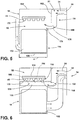
FIG. 5 is a side schematic view of the ice-making compartment including the inlet duct having the second branch, according to at least one example; -
FIG. 6 is a side schematic view of the ice-making compartment including the inlet duct having the second branch with left and right portions extending proximate left and right sides of an ice tray, according to at least one example; -
FIG. 7 is a side schematic view of the ice-making compartment including a deflector, according to at least one example; and -
FIG. 8 is a side schematic view of the ice-making compartment including staggered ice trays, according to at least one example. - For purposes of description herein the terms "upper," "lower," "right," "left," "rear," "front," "vertical," "horizontal," and derivatives thereof shall relate to the device as oriented in
FIG. 1 . However, it is to be understood that the device may assume various alternative orientations and step sequences, except where expressly specified to the contrary. It is also to be understood that the specific devices and processes illustrated in the attached drawings, and described in the following specification are simply exemplary embodiments of the inventive concepts defined in the appended claims. Hence, specific dimensions and other physical characteristics relating to the embodiments disclosed herein are not to be considered as limiting, unless the claims expressly state otherwise. - Referring to
FIGS. 1-8 ,reference numeral 10 generally designates a refrigerator including an ice-makingcompartment 14. The ice-makingcompartment 14 includes ahousing 18 defining aninlet aperture 22 and anoutlet aperture 26. Aninlet duct 30 is in fluid communication with theinlet aperture 22 to direct incomingair 34 into thehousing 18. Anoutlet duct 38 is in fluid communication with theoutlet aperture 26 to direct theoutgoing air 42 out of thehousing 18. Additionally, anice tray 46 may be positioned within aninterior 50 of thehousing 18. - Referring to
FIG. 1 , the illustratedrefrigerator 10 has acabinet 54. The refrigerator includes arefrigerator compartment 58 and/or afreezer compartment 62. Therefrigerator 10 includes arefrigerator compartment door 66 proximate therefrigerator compartment 58 and afreezer compartment door 70 proximate thefreezer compartment 62. Therefrigerator 10 depicted inFIG. 1 shows therefrigerator compartment 58 having left and rightrefrigerator compartment doors style refrigerator compartment 58. Additionally, therefrigerator 10 depicted inFIG. 1 shows thefreezer compartment 62 positioned below therefrigerator compartment 58. It will be contemplated that therefrigerator 10 may include other styles of refrigerators such as, for example, side-by-side refrigerators or single door refrigerator compartments. - With further reference to
FIG. 1 , therefrigerator 10 includes arefrigeration system 74. Therefrigeration system 74 may be positioned in therefrigerator compartment 58 or in thefreezer compartment 62. Therefrigeration system 74 may also be positioned proximate arear wall 78 of therefrigerator 10. Therefrigerator system 74 includes anevaporator 82, acondenser 86, and acompressor 90. The ice-makingcompartment 14 ofFIG. 1 is shown positioned within therefrigerator compartment door 66. The ice-makingcompartment 14 may be positioned within theinterior 98 of thecabinet 54, within therefrigerator compartment door 66, or thefreezer compartment door 70. However, it will be contemplated that the ice-makingcompartment 14 may be positioned in thefreezer compartment 62 or other locations within therefrigerator 10 without deviating from the teachings herein. - Referring now to
FIG. 2 , anice storage bin 102 may be positioned within thehousing 18 of the ice-makingcompartment 14. Theice storage bin 102 is shown positioned on abottom wall 106 of thehousing 18. Theice storage bin 102 may also include an ice grinder area. In various examples, theice storage bin 102 has a height hstorage in a range of from approximately 150 mm to approximately 200 mm. The width and depth of theice storage bin 102 may be substantially similar to the width w and depth d of thehousing 18. As illustrated, the ice-makingcompartment 14 includes anice tray 46 positioned in thehousing 18. Theice tray 46 defines more than oneice cube cavity 110. However, theice tray 46 may define multipleice cube cavities 110. In various examples, theice tray 46 is positioned in anupper portion 114 of thehousing 18 and positioned above theice storage bin 102. However, theice tray 46 may be positioned in other locations within thehousing 18. Theice tray 46 may be coupled to at least onesidewall 118 of thehousing 18. - In various examples, the
housing 18 has a height hhousing in a range of from approximately 250 mm to approximately 300 mm. Thehousing 18 has a depth d in a range of from approximately 130 mm to approximately 180 mm. Additionally, thehousing 18 has a width w (i.e., extend into the paper) in a range of from approximately 250 mm to approximately 300 mm. Thehousing 18 defines theinlet aperture 22 and theoutlet aperture 26. As illustrated, theinlet aperture 22 is positioned in theupper portion 114 of thehousing 18 and theoutlet aperture 26 is positioned in alower portion 116 of thehousing 18. In other words, theinlet aperture 22 may be positioned at a first height hinlet and theoutlet aperture 26 may be positioned at a second height houtlet where the first height hinlet may be above the second height houtlet. Theoutlet aperture 26 may also be positioned proximate theice storage bin 102. It may be advantageous to have theoutlet aperture 26 positioned proximate theice storage bin 102 to directincoming air 34 through theice storage bin 102 before theoutgoing air 42 exits thehousing 18 through theoutlet aperture 26. - Still referring to
FIG. 2 , theinlet duct 30 is in fluid communication with theinlet aperture 22 and configured to direct theincoming air 34 into thehousing 18 from the evaporator 82 (FIG. 1 ). Accordingly, theinlet duct 30 is positioned at the first height hinlet, which is illustrated as being within theupper portion 114 of thehousing 18. Theinlet duct 30 is coupled to afirst sidewall 122 of thehousing 18. Thefirst sidewall 122 may be, for example, a front side, a rear side, or a lateral side of thehousing 18. In the depicted example, thefirst sidewall 122 is illustrated as a rear side of the ice-makingcompartment 14. Theinlet aperture 22 andinlet duct 30 may be positioned to direct theincoming air 34 to theice tray 46 positioned within thehousing 18. - As illustrated, the
inlet duct 30 includes afirst branch 126 where thefirst branch 126 has aplurality channels 130, for example a plurality of first branch channels. Thechannels 130 assist in directing theincoming air 34 to a plurality of locations, such as, for example, a plurality of first branch locations, on afirst surface 134 of theice tray 46. Thefirst surface 134 of theice tray 46 may be a top surface, a bottom surface, or other side surface of theice tray 46. In the depicted example, thefirst surface 134 is shown as a top surface of theice tray 46. Thechannels 130 may be oriented within thehousing 18 to direct theincoming air 34 air from theinlet duct 30 to more than oneice cube cavity 110 within theice tray 46. Thechannels 130 may also direct theincoming air 34 to eachice cube cavity 110 within theice tray 46. It may be advantageous to include thechannels 130 to improve airflow distribution across theice tray 46 and thereby increase ice rates through more balanced distribution of theincoming air 34. - Referring still to
FIG. 2 , theoutlet duct 38 is in fluid communication with theoutlet aperture 26 and configured to directoutgoing air 42 from theinterior 50 of thehousing 18 to the evaporator 82 (FIG. 1 ). As illustrated, theoutlet aperture 26 and theoutlet duct 38 are positioned at the second height houtlet of thehousing 18. The second height houtlet is positioned closer to thebottom wall 106 of thehousing 18 compared to the first height hinlet of theinlet aperture 22 andinlet duct 30. In various examples, theinlet duct 30 may be coupled to thefirst sidewall 122 of thehousing 18 and theoutlet duct 38 may be coupled to asecond sidewall 138 of thehousing 18 where thesecond sidewall 138 opposes thefirst sidewall 122. Accordingly, the inlet andoutlet apertures second sidewalls housing 18. - As illustrated in
FIG. 2 , thehousing 18 includes a steppedtop wall 142. In such examples, aspace 146 between the steppedtop wall 142 and theice tray 46 decreases with eachstep 150. The steppedtop wall 142 includes more than onestep 150. The steppedtop wall 142 may also includemultiple steps 150. Thesteps 150 of the steppedtop wall 142 may correspond with and/or align with thechannels 130 of theinlet duct 30. For example, thespace 146 between the steppedtop wall 142 and theice tray 46 decreases with thestep 150 at a point where thechannel 130 directs theincoming air 34 towards theice tray 46. It may be advantageous to align thesteps 150 with thechannels 130 to improve airflow through thechannels 130 to theice tray 46. Further, a height hchannel of thechannels 130 may decrease with eachstep 150. As such, the height hchannel of proximate theinlet duct 30 is greater than the height hchannel proximate asidewall 118 positioned opposite theinlet duct 30. The decreasing height hchannel may be advantageous to improve airflow through thechannels 130 farther from theinlet duct 30 to provide more evenincoming air 34 across theice tray 46. - Referring now to
FIG. 3 , theinlet duct 30 is illustrated having more than onebranch 126 to directincoming air 34 to theice tray 46. For example, theinlet duct 30 includes thefirst branch 126 and asecond branch 158. In the depicted example, thefirst branch 126 is shown as an upper branch and thesecond branch 158 is shown as a lower branch. Thefirst branch 126 may extend along the steppedtop wall 142 of thehousing 18 and include thechannels 130. Thesecond branch 158 may extend downward from theinlet aperture 22. A dividingwall 162 is positioned within thehousing 18 to divide thefirst branch 126 from thesecond branch 158. In examples including the first andsecond branches inlet duct 30, theupper portion 114 of thehousing 18 may have a greater depth d than thelower portion 116 of thehousing 18 to accommodate thesecond branch 158. Thefirst branch 126 directsincoming air 34 to thefirst surface 134 of theice tray 46. Thesecond branch 158 directsincoming air 34 to asecond surface 170 of theice tray 46. In various examples, thefirst surface 134 of theice tray 46 may be the top surface and thesecond surface 170 may be the bottom surface of theice tray 46 such that thechannels 130 may direct theincoming air 34 to the plurality locations on the top surface of theice tray 46. It will also be contemplated that thefirst branch 126 may not include thechannels 130. - Referring now to
FIGS. 3 and 4 , theoutlet aperture 26 may be positioned onvarious sidewalls 118 of thehousing 18. As shown inFIG. 3 , theinlet aperture 22 and theoutlet aperture 26 are both defined by thefirst sidewall 122 of thehousing 18. Accordingly, theinlet duct 30 and theoutlet duct 38 are both coupled to thefirst sidewall 122. Alternatively, as shown inFIG. 4 , theinlet duct 30 is defined by thefirst sidewall 122 and theoutlet duct 38 is defined by the opposingsecond wall 174. The orientation of the inlet andoutlet apertures interior 50 of thehousing 18. It will be understood that theoutlet aperture 26 may be defined by thefirst sidewall 122 or thesecond sidewall 138 with each of theinlet duct 30 configurations without deviating from the teachings herein. - Referring now to
FIG. 5 , as illustrated, theinlet duct 30 includes thesecond branch 158 where thesecond branch 158 directsincoming air 34 to the second surface 170 (e.g., the bottom surface) of theice tray 46. In such examples, the ice-makingcompartment 14 does not include thefirst branch 126 to direct theincoming air 34 to the first surface 134 (e.g., the top surface) of the ice tray as shown inFIG.3 . Referring still toFIG. 5 , thesecond branch 158 may extend downwards towards thebottom wall 106 of thehousing 18 from theinlet aperture 22 and open towards the interior 50 of thehousing 18. In such examples, theupper portion 114 of thehousing 18 may have a greater depth d compared to thelower portion 116 of thehousing 18. As illustrated, abottom 176 of thesecond branch 158 is rounded such that theincoming air 34 is guided into the interior 50 of thehousing 18. Aninterior edge portion 178 of the bottom 176 of thesecond branch 158 extends upwards from the bottom 176 to assist in guiding theincoming air 34 to theice tray 46 instead of towards theice storage bin 102. The dividingwall 162 may also be included to separate thesecond branch 158 from theinterior 50 of thehousing 18 to direct theincoming air 34 downwards in thesecond branch 158. Additionally, as illustrated inFIG. 5 , thehousing 18 includes a flattop wall 182 such that the flattop wall 182 does not include thesteps 150 shown inFIG. 2 . Referring still toFIG. 5 , the flattop wall 182 may be advantageous for improved airflow and/or cross-airflow within theinterior 50 of thehousing 18 based on the configuration of theinlet duct 30. It will be understood that either the stepped top wall 142 (FIG. 2 ) or the flattop wall 182 may be utilized for each of theinlet duct 30 configurations without deviating from the teachings herein. - Referring now to
FIG. 6 , as illustrated, thesecond branch 158 included a plurality ofchannels 130, for example a plurality of second branch channels. Thesecond branch 158 extends under theice tray 46 and includes thechannels 130 to directincoming air 34 to a plurality locations, such as, for example, a plurality of second branch locations, on thesecond surface 170 of theice tray 46. Thechannels 130 may direct theincoming air 34 to the second surface 170 (e.g., the bottom surface) of eachice cube cavity 110 within theice tray 46. In various examples, thesecond branch 158 may divide into aleft section 186 and aright section 190. The left andright sections housing 18 proximate left and right side surfaces 194, 198 of theice tray 46, respectively. Each of the left andright sections channels 130 for directing theincoming air 34 towards theice tray 46. It may be advantageous to include the left andright sections entire ice tray 46 without substantially interfering with the ice-making process (i.e., ice cubes moving from theice tray 46 to the ice storage bin 102). - In various examples, the ice-making
compartment 14 may include thesecond branch 158 having the left andright sections channels 130 and the first branch 126 (FIG. 2 ). Theincoming air 34 may then be directed to both the first andsecond surfaces ice tray 46. For example, theincoming air 34 may be directed to a plurality of locations on thefirst surface 134 of theice tray 46, thesecond surface 170 of theice tray 46, or both the first andsecond surfaces ice tray 46 depending on the configuration of the first andsecond branches inlet duct 30. - Referring now to
FIG. 7 , as illustrated, the ice-makingcompartment 14 also includes adeflector 202 positioned within thehousing 18. Thedeflector 202 is shown positioned in theupper portion 114 of thehousing 18 opposing theinlet aperture 22 andinlet duct 30. The deflector may be coupled to thesecond sidewall 138 of thehousing 18. However, thedeflector 202 may be integrally formed with thehousing 18. Thedeflector 202 operates to redirect theincoming air 34 to thesecond surface 170 of theice tray 46. In other words, thedeflector 202 operates to redirect theincoming air 34 fromfirst surface 134 of theice tray 46 to thesecond surface 170 of theice tray 46. It will be understood that thedeflector 202 may redirect theincoming air 34 from the top surface to the bottom surface of theice tray 46 based on the configuration of theinlet duct 30. It will also be understood thatdeflector 202 may redirect theincoming air 34 from the bottom surface to the top surface of theice tray 46 based on the configuration of theinlet duct 30. In various examples, thedeflector 202 forms an arcuate shape. Thedeflector 202 may also form a hemispherical shape, a substantially symmetrical concave shape, or a C-shape. However, it will be contemplated that thedeflector 202 may form another shape such as, for example, a convex shape or an asymmetrical concave shape depending on the desired direction of the deflectedincoming air 34. - As illustrated, the
deflector 202 extends past at least one ice-cube cavity 110 of theice tray 46. However, thedefector 202 may not extend past anice cube cavity 110 or may extend past multipleice cube cavities 110 based on the desired path for redirecting theincoming air 34. Thedeflector 202 may also be adjustable to improve and/or maximize airflow to thesecond surface 170 of theice tray 46. Thedeflector 202 may be adjustable by, for example, changing the shape of thedeflector 202 and/or changing the angle of thedeflector 202 within thehousing 18. In operation, theincoming air 34 exits theinlet duct 30 through theinlet aperture 22 and flows over thefirst surface 134 of theice tray 46. Theincoming air 34 comes into contact with thedeflector 202 and then is redirected by thedeflector 202 to flow over thesecond surface 170 of theice tray 46. Theincoming air 34 may then travel through theice storage bin 102 and through theoutlet aperture 26. Use of thedeflector 202 may be advantageous to maximize the surface area of theice tray 46 exposed to theincoming air 34 and thereby maximize the efficiency of the use of theincoming air 34. - Referring now to
FIG. 8 , the ice-makingcompartment 14 is illustrated includingstaggered ice trays 206. Thestaggered ice trays 206 include more than oneice tray 46 positioned at varying heights within theinterior 50 of thehousing 18. Theice trays 46 are spaced apart such thatincoming air 34 may flow between theice trays 46. Theinlet duct 30 may direct theincoming air 34 to each of theice trays 46. In various examples, theinlet duct 30 may include more than onebranch 126 to direct theincoming air 34. For example, theinlet duct 30 includes thefirst branch 126, thesecond branch 158, and athird branch 210 directing theincoming air 34 into the interior 50 of thehousing 18. As illustrated, the first, second, andthird branches first branch 126 is higher than thesecond branch 158, which is higher than thethird branch 210. At least onedividing wall 162 is included to direct theincoming air 34 to the various locations of thestaggered ice trays 206. The varying heights of the first, second, andthird branches inlet duct 30 may correspond with and/or align with the varying heights of thestaggered ice trays 206. Accordingly, theinlet duct 30 directs theincoming air 34 to at least onesurface 214 of each of thestaggered ice trays 206. The first, second, andthird branches incoming air 34 to afirst ice tray 46A, asecond ice tray 46B, and athird ice tray 46C of thestaggered ice trays 206, respectively. The first, second, andthird ice trays 46A-C are shown as an upper ice tray, a middle ice tray, and a lower ice tray, respectively. The first, second, andthird branches ice trays 46. However, the first, second, andthird branches ice trays 46. In other words, theinlet duct 30 may direct air to at least one of the top and bottom surfaces of each of thestaggered ice trays 206. It will also be contemplated than fewer ormore ice trays 46 may be included within the staggeredice tray 206. - In various examples, the
staggered ice trays 206 includes at least twoice trays 46 spaced at different heights within thehousing 18 to have the first andsecond ice trays inlet duct 30 directs theincoming air 34 between theice trays 46 such that theincoming air 34 is directed at thesecond surface 170 of thefirst ice tray 46A and thefirst surface 134 of thesecond ice tray 46B. In other words, theincoming air 34 may be directed at the bottom surface of the upper ice tray and the top surface of the lower ice tray. Use of thestaggered ice trays 206 may be advantageous to improve airflow and/or cross airflow within thehousing 18 and across theice trays 46. - According to at least one aspect, a refrigerator includes a cabinet and a refrigeration system including an evaporator. An ice-making compartment may be positioned within the cabinet. The ice-making compartment includes a housing defining an inlet aperture and an upper portion of the housing and an outlet aperture. An ice storage bin may be positioned in a lower portion of the housing. An ice tray may be positioned above the ice storage bin. An inlet duct may be in fluid communication with the inlet aperture and may be configured to direct air into the housing from the evaporator. The inlet duct may include a first branch having a plurality of first branch channels to direct air to a plurality of first branch locations on a first surface of the ice tray and a second branch to direct air to a second surface of the ice tray. An outlet duct may be in fluid communication with the outlet aperture and may be configured to direct air from the housing to the evaporator.
- According to another aspect, the first surface of the ice tray may be a top surface and the second surface of the ice tray may be a bottom surface. The panels may direct air to the plurality of first branch locations on the top surface.
- According to another aspect, the first surface of the ice tray may be a bottom surface and the second surface of the ice tray may be a top surface. The plurality of first branch channels may direct air to the plurality of first branch locations on the bottom surface.
- According to still another aspect, the second branch of the inlet duct may include a plurality of second branch channels to direct air to a plurality of second branch locations on the second surface of the ice tray.
- According to another aspect, the inlet and outlet apertures may be defined by opposing sidewalls of the housing.
- According to yet another aspect, the plurality of first branch channels may be oriented within the housing to direct air from the inlet duct each ice cube cavity within the ice tray.
- According to another aspect, the housing may include a stepped top wall. A space between the stepped top wall and the ice bay may decrease with each step.
- According to another aspect, the steps of the stepped top wall may align with the plurality of first branch channels of the inlet duct.
- According to at least one aspect, and ice-making compartment for an appliance may include a housing defining an inlet aperture and an outlet aperture. An outlet duct may be in fluid communication with the outlet aperture and may be configured to direct air out of the housing. In inlet duct may be in fluid communication with the inlet aperture and may be configured to direct air into the housing. Staggered ice trays may be positioned at various heights within an interior of the housing. The inlet duct may direct air to each of the staggered ice trays.
- According to another aspect, the inlet duct may include more than one branch to direct air each of the staggered ice trays.
- According to another aspect, the branches of the inlet duct may be stacked vertically to align with the varying heights of the staggered ice trays.
- According to still another aspect, the inlet duct may direct air to at least one of a top and bottom surface of each of the staggered ice trays.
- According to another aspect, a deflector may be positioned in an upper portion of the housing opposing the inlet duct.
- According to yet another aspect, the staggered ice trays may include at least two ice trays. The inlet duct may direct air between the two ice trays such that the air may be directed at a bottom surface of the first ice tray and a top surface of the second ice tray.
- According to at least one aspect, and ice-making compartment for an appliance may include housing defining an inlet publisher and an outlet aperture. An ice tray may be positioned within the housing. The inlet duct may be in fluid communication with the inlet aperture. The inlet aperture may be positioned at a first height on a first surface of the housing direct air to the ice tray. An outlet duct may be in fluid communication with outlet aperture. The outlet aperture may be positioned on a second height on a second surface of the housing. An arcuate deflector may be positioned in an upper portion of the housing opposing the inlet duct. The arcuate deflector may direct air from a first surface is ice tray to a second surface of ice tray.
- According to another aspect, the second height may be lower than the first height and may be proximate an ice storage bin to direct air through the ice storage been before exiting housing through the outlet duct.
- According to another aspect, the housing may include a stepped top wall.
- According to still another aspect, the first surface may be a top surface of the ice tray and the second surface may be a bottom surface of ice tray.
- According to another aspect, the arcuate deflector may be adjustable to maximize airflow to the bottom surface of the ice tray.
- According to another aspect, the inlet duct may include more than one branch to direct air to the ice tray.
- For purposes of this disclosure, the term "coupled" (in all of its forms, couple, coupling, coupled, etc.) generally means the joining of two components (electrical or mechanical) directly or indirectly to one another. Such joining may be stationary in nature or movable in nature. Such joining may be achieved with the two components (electrical or mechanical) and any additional intermediate members being integrally formed as a single unitary body with one another or with the two components. Such joining may be permanent in nature or may be removable or releasable in nature unless otherwise stated.
Claims (15)
- A refrigerator (10), comprising:a cabinet (54);a refrigeration system (74) including an evaporator (82); andan ice-making compartment (14) within the cabinet (54), the ice-making compartment (14) comprising:a housing (18) defining an inlet aperture (22) on a top portion (114) of the housing (18) and an outlet aperture (26);an ice storage bin (102) positioned in a bottom portion (116) of the housing (18);at least one ice tray (46) positioned in the top portion (114) of the housing (18) and over the ice storage bin (102);an inlet duct (30) in fluid communication with the inlet aperture (22) and configured to direct air into the housing (18) from the evaporator (82), wherein the inlet duct (30) includes a first branch (126) having multiple channels (130) to direct air to multiple locations on a first surface (134) of the ice tray (46) and a second branch (158) to direct air to a second surface (170) of the ice tray (46); andan outlet duct (38) in fluid communication with the outlet aperture (26) and configured to direct air from the housing (18) to the evaporator (82).
- The refrigerator (10) of claim 1, wherein the first surface (134) of the at least one ice tray (46) is a top surface and the second surface (170) of the at least one ice tray (46) is a bottom surface, such that the channels (130) direct air to multiple locations on the top surface.
- The refrigerator (10) of claim 1, wherein the first surface (134) of the at least one ice tray (46) is a bottom surface and the second surface (170) of the at least one ice tray (46) is a top surface, such that the channels (130) direct air to multiple locations on the bottom surface.
- The refrigerator (10) of any one of claims 1-3, wherein the second branch (158) of the inlet duct (30) includes multiple channels (130) to direct air to multiple locations on the second surface (170) of the at least one ice tray (46).
- The refrigerator (10) of any one of claims 1-4, wherein the inlet and outlet apertures (22, 26) are defined by opposing sidewalls (118) of the housing (18).
- The refrigerator of any one of claims 1-5, wherein the channels (130) are oriented within the housing (18) to direct air from the inlet duct (30) to each ice cube cavity (110) of the at least one ice tray (46).
- The refrigerator (10) of any one of claims 1-6, wherein the housing (18) includes a stepped top wall (142), wherein a space (146) between the stepped top wall (142) and the at least one ice tray (46) decreases with each step (150).
- The refrigerator (10) of claim 7, wherein the steps (150) of the stepped top wall (142) align with the channels (130) of the inlet duct (30).
- The refrigerator (10) of any one of claims 1-8, wherein the inlet aperture (22) is positioned at a first height on a first sidewall (122) of the housing (18), and wherein the outlet aperture (26) is positioned at a second height on a second sidewall (138) of the housing (18).
- The refrigerator (10) of claim 9, wherein the second height is lower than the first height and proximate the ice storage bin (102) to direct air through the ice storage bin (102) before exiting the housing (18) through the outlet duct (38).
- The refrigerator (10) of any one of claims 1-10, further comprising:
an arcuate deflector (202) positioned in the top portion (114) of the housing (18) opposing the inlet duct (30). - The refrigerator (10) of claim 11, wherein the arcuate deflector (202) is adjustable to maximize airflow to a bottom surface of the at least one ice tray (46).
- The refrigerator (10) of any one of claims 1-12, wherein the at least one ice tray (46) includes staggered ice trays (206) positioned at varying heights within an interior (50) of the housing (18), wherein the inlet duct (30) directs air to each of the staggered ice trays (206).
- The refrigerator (10) of claim 13, wherein the staggered ice trays (206) includes at least two ice trays (46) and the inlet duct (30) directs air between the two ice trays (46) such that the air is directed at a bottom surface of a first ice tray (46A) and a top surface of a second ice tray (46B).
- The refrigerator (10) of claim 14, wherein the first and second branches (126, 158) of the inlet duct (30) are stacked vertically to align with the varying heights of the staggered ice trays (206).
Applications Claiming Priority (1)
| Application Number | Priority Date | Filing Date | Title |
|---|---|---|---|
| US16/251,141 US11112163B2 (en) | 2019-01-18 | 2019-01-18 | Ice-making compartment for an appliance |
Publications (3)
| Publication Number | Publication Date |
|---|---|
| EP3693688A2 true EP3693688A2 (en) | 2020-08-12 |
| EP3693688A3 EP3693688A3 (en) | 2020-09-16 |
| EP3693688B1 EP3693688B1 (en) | 2023-06-14 |
Family
ID=69157663
Family Applications (1)
| Application Number | Title | Priority Date | Filing Date |
|---|---|---|---|
| EP20151075.7A Active EP3693688B1 (en) | 2019-01-18 | 2020-01-09 | Ice-making compartment for an appliance |
Country Status (2)
| Country | Link |
|---|---|
| US (3) | US11112163B2 (en) |
| EP (1) | EP3693688B1 (en) |
Cited By (1)
| Publication number | Priority date | Publication date | Assignee | Title |
|---|---|---|---|---|
| CN116472431A (en) * | 2020-11-19 | 2023-07-21 | Lg电子株式会社 | refrigerator |
Families Citing this family (1)
| Publication number | Priority date | Publication date | Assignee | Title |
|---|---|---|---|---|
| US11112163B2 (en) * | 2019-01-18 | 2021-09-07 | Whirlpool Corporation | Ice-making compartment for an appliance |
Family Cites Families (31)
| Publication number | Priority date | Publication date | Assignee | Title |
|---|---|---|---|---|
| US3403533A (en) * | 1966-10-07 | 1968-10-01 | Gen Motors Corp | Refrigerator with upright dividing wall |
| NL7608165A (en) | 1976-07-23 | 1978-01-25 | Philips Nv | DEVICE FOR CONTROLLING INFORMATION FLOWS. |
| JPS5951435B2 (en) | 1977-10-21 | 1984-12-13 | イビデン株式会社 | Method for manufacturing decorative board with uneven wood grain pattern |
| JPS612461Y2 (en) * | 1979-09-05 | 1986-01-27 | ||
| JPS5640368A (en) | 1979-09-12 | 1981-04-16 | Sanyo Electric Co Ltd | Horizontal synchronizing signal detecting circuit |
| US5012655A (en) * | 1989-11-03 | 1991-05-07 | Philip Chatterton | Filling assembly for ice trays |
| MXPA04003411A (en) | 2004-04-07 | 2005-10-11 | Mabe De Mexico S De R L De C V | Device for making ice in refrigerated cabinets. |
| KR100705182B1 (en) * | 2006-05-29 | 2007-04-09 | 엘지전자 주식회사 | Ice Tray Assembly For Refrigerator |
| US20080034780A1 (en) * | 2006-08-11 | 2008-02-14 | Samsung Electronics Co., Ltd. | Ice making apparatus and refrigerator having the same |
| KR100809749B1 (en) | 2007-03-28 | 2008-03-04 | 엘지전자 주식회사 | Ice Maker Assembly In Refrigerator |
| KR101406187B1 (en) | 2007-06-04 | 2014-06-13 | 삼성전자주식회사 | Ice maker and refrigerator with it |
| KR20100133155A (en) * | 2009-06-11 | 2010-12-21 | 엘지전자 주식회사 | Refrigerator with ice maker |
| JP5586534B2 (en) | 2011-07-01 | 2014-09-10 | 三菱電機株式会社 | Freezer refrigerator |
| KR101957793B1 (en) | 2012-01-03 | 2019-03-13 | 엘지전자 주식회사 | Refrigerator |
| KR101962139B1 (en) | 2013-01-03 | 2019-03-26 | 엘지전자 주식회사 | Icemaker and controlling method of the same |
| DE102014008876A1 (en) | 2014-03-21 | 2015-09-24 | BSH Hausgeräte GmbH | Fridge and / or freezer |
| US20150276298A1 (en) * | 2014-03-25 | 2015-10-01 | Whirlpool Corporation | Apparatuses and methods to improve air flow in on-the-door icemakers |
| US10228179B2 (en) | 2014-10-23 | 2019-03-12 | Whirlpool Corporation | In door ice bin for an automatic ice maker |
| US9829235B2 (en) * | 2015-03-02 | 2017-11-28 | Whirlpool Corporation | Air flow diverter for equalizing air flow within an ice making appliance |
| EP3303952A1 (en) * | 2015-06-02 | 2018-04-11 | Arçelik Anonim Sirketi | A refrigerator wherein ice is obtained quickly |
| KR101715806B1 (en) * | 2015-06-16 | 2017-03-13 | 동부대우전자 주식회사 | Ice making system of refrigerator and ice making method thereof |
| KR101705655B1 (en) * | 2015-06-18 | 2017-02-10 | 동부대우전자 주식회사 | Ice maker for refrigerator and manufacturing method for the same |
| KR102712077B1 (en) | 2015-08-31 | 2024-10-02 | 엘지전자 주식회사 | refrigerator |
| US10101074B2 (en) * | 2016-04-21 | 2018-10-16 | Electrolux Home Products, Inc. | Ice maker air flow ribs |
| KR20170123513A (en) | 2016-04-29 | 2017-11-08 | 동부대우전자 주식회사 | Ice making apparatus and refrigerator including the same |
| US10156394B2 (en) * | 2016-11-18 | 2018-12-18 | Haier Us Appliance Solutions, Inc. | Air flow and drainage system for ice maker |
| US10883751B2 (en) * | 2017-09-28 | 2021-01-05 | Nidec Sankyo Corporation | Ice making machine |
| US10739053B2 (en) | 2017-11-13 | 2020-08-11 | Whirlpool Corporation | Ice-making appliance |
| KR102496329B1 (en) * | 2018-03-30 | 2023-02-07 | 삼성전자주식회사 | Refrigerator |
| US11112163B2 (en) * | 2019-01-18 | 2021-09-07 | Whirlpool Corporation | Ice-making compartment for an appliance |
| US11493252B2 (en) * | 2020-06-30 | 2022-11-08 | Electrolux Home Products, Inc. | Ice maker assembly for a cooling device |
-
2019
- 2019-01-18 US US16/251,141 patent/US11112163B2/en active Active
-
2020
- 2020-01-09 EP EP20151075.7A patent/EP3693688B1/en active Active
-
2021
- 2021-08-06 US US17/395,630 patent/US11879680B2/en active Active
-
2023
- 2023-12-05 US US18/529,177 patent/US12624883B2/en active Active
Cited By (4)
| Publication number | Priority date | Publication date | Assignee | Title |
|---|---|---|---|---|
| CN116472431A (en) * | 2020-11-19 | 2023-07-21 | Lg电子株式会社 | refrigerator |
| US20240003609A1 (en) * | 2020-11-19 | 2024-01-04 | Lg Electronics Inc. | Refrigerator |
| EP4249833A4 (en) * | 2020-11-19 | 2024-09-18 | LG Electronics Inc. | FRIDGE |
| US12584673B2 (en) * | 2020-11-19 | 2026-03-24 | Lg Electronics Inc. | Refrigerator |
Also Published As
| Publication number | Publication date |
|---|---|
| US20240118011A1 (en) | 2024-04-11 |
| EP3693688B1 (en) | 2023-06-14 |
| US20200232697A1 (en) | 2020-07-23 |
| US11112163B2 (en) | 2021-09-07 |
| US12624883B2 (en) | 2026-05-12 |
| EP3693688A3 (en) | 2020-09-16 |
| US20210364219A1 (en) | 2021-11-25 |
| US11879680B2 (en) | 2024-01-23 |
Similar Documents
| Publication | Publication Date | Title |
|---|---|---|
| US11686521B2 (en) | Refrigerator | |
| US11525610B2 (en) | Refrigerator | |
| US12624883B2 (en) | Ice-making compartment for an appliance | |
| KR970022103A (en) | Refrigerator | |
| CA2365751A1 (en) | Cooling air supplying device in refrigerator | |
| CN102853609B (en) | freezer | |
| KR102013589B1 (en) | Refrigerator | |
| KR20200095887A (en) | Refrigerator | |
| KR20180129472A (en) | Refrigerator | |
| US12320574B2 (en) | Refrigerator | |
| EP3916322B1 (en) | REFRIGERATOR | |
| KR101132455B1 (en) | A refrigerator | |
| EP4361536A1 (en) | Refrigerator | |
| KR100398497B1 (en) | Side by side type refrigerator | |
| KR200165703Y1 (en) | Shelf duct of a refrigerator | |
| KR200290391Y1 (en) | Refrigerator | |
| JP7148675B2 (en) | refrigerator | |
| CN222165337U (en) | Refrigerator | |
| CN221684883U (en) | refrigerator | |
| CN116481224A (en) | Refrigerating appliance | |
| CN220338778U (en) | Refrigeration equipment | |
| JP7129925B2 (en) | refrigerator | |
| KR20010047667A (en) | Refrigerator with multiple cooling system | |
| KR100859459B1 (en) | Ceiling type side by side refrigerator | |
| KR100206808B1 (en) | Cooling air circulating device of refrigerator |
Legal Events
| Date | Code | Title | Description |
|---|---|---|---|
| PUAI | Public reference made under article 153(3) epc to a published international application that has entered the european phase |
Free format text: ORIGINAL CODE: 0009012 |
|
| STAA | Information on the status of an ep patent application or granted ep patent |
Free format text: STATUS: THE APPLICATION HAS BEEN PUBLISHED |
|
| AK | Designated contracting states |
Kind code of ref document: A2 Designated state(s): AL AT BE BG CH CY CZ DE DK EE ES FI FR GB GR HR HU IE IS IT LI LT LU LV MC MK MT NL NO PL PT RO RS SE SI SK SM TR |
|
| AX | Request for extension of the european patent |
Extension state: BA ME |
|
| PUAL | Search report despatched |
Free format text: ORIGINAL CODE: 0009013 |
|
| AK | Designated contracting states |
Kind code of ref document: A3 Designated state(s): AL AT BE BG CH CY CZ DE DK EE ES FI FR GB GR HR HU IE IS IT LI LT LU LV MC MK MT NL NO PL PT RO RS SE SI SK SM TR |
|
| AX | Request for extension of the european patent |
Extension state: BA ME |
|
| RIC1 | Information provided on ipc code assigned before grant |
Ipc: F25C 5/20 20180101AFI20200810BHEP Ipc: F25D 17/06 20060101ALI20200810BHEP Ipc: F25D 23/04 20060101ALN20200810BHEP Ipc: F25C 1/04 20180101ALI20200810BHEP |
|
| STAA | Information on the status of an ep patent application or granted ep patent |
Free format text: STATUS: REQUEST FOR EXAMINATION WAS MADE |
|
| 17P | Request for examination filed |
Effective date: 20210312 |
|
| RBV | Designated contracting states (corrected) |
Designated state(s): AL AT BE BG CH CY CZ DE DK EE ES FI FR GB GR HR HU IE IS IT LI LT LU LV MC MK MT NL NO PL PT RO RS SE SI SK SM TR |
|
| RIC1 | Information provided on ipc code assigned before grant |
Ipc: F25D 23/04 20060101ALN20230203BHEP Ipc: F25C 1/04 20060101ALI20230203BHEP Ipc: F25D 17/06 20060101ALI20230203BHEP Ipc: F25C 5/20 20180101AFI20230203BHEP |
|
| GRAP | Despatch of communication of intention to grant a patent |
Free format text: ORIGINAL CODE: EPIDOSNIGR1 |
|
| STAA | Information on the status of an ep patent application or granted ep patent |
Free format text: STATUS: GRANT OF PATENT IS INTENDED |
|
| INTG | Intention to grant announced |
Effective date: 20230327 |
|
| GRAS | Grant fee paid |
Free format text: ORIGINAL CODE: EPIDOSNIGR3 |
|
| GRAA | (expected) grant |
Free format text: ORIGINAL CODE: 0009210 |
|
| STAA | Information on the status of an ep patent application or granted ep patent |
Free format text: STATUS: THE PATENT HAS BEEN GRANTED |
|
| AK | Designated contracting states |
Kind code of ref document: B1 Designated state(s): AL AT BE BG CH CY CZ DE DK EE ES FI FR GB GR HR HU IE IS IT LI LT LU LV MC MK MT NL NO PL PT RO RS SE SI SK SM TR |
|
| REG | Reference to a national code |
Ref country code: CH Ref legal event code: EP |
|
| REG | Reference to a national code |
Ref country code: DE Ref legal event code: R096 Ref document number: 602020012387 Country of ref document: DE |
|
| REG | Reference to a national code |
Ref country code: AT Ref legal event code: REF Ref document number: 1579489 Country of ref document: AT Kind code of ref document: T Effective date: 20230715 |
|
| REG | Reference to a national code |
Ref country code: LT Ref legal event code: MG9D |
|
| REG | Reference to a national code |
Ref country code: NL Ref legal event code: MP Effective date: 20230614 |
|
| PG25 | Lapsed in a contracting state [announced via postgrant information from national office to epo] |
Ref country code: SE Free format text: LAPSE BECAUSE OF FAILURE TO SUBMIT A TRANSLATION OF THE DESCRIPTION OR TO PAY THE FEE WITHIN THE PRESCRIBED TIME-LIMIT Effective date: 20230614 Ref country code: NO Free format text: LAPSE BECAUSE OF FAILURE TO SUBMIT A TRANSLATION OF THE DESCRIPTION OR TO PAY THE FEE WITHIN THE PRESCRIBED TIME-LIMIT Effective date: 20230914 Ref country code: ES Free format text: LAPSE BECAUSE OF FAILURE TO SUBMIT A TRANSLATION OF THE DESCRIPTION OR TO PAY THE FEE WITHIN THE PRESCRIBED TIME-LIMIT Effective date: 20230614 |
|
| REG | Reference to a national code |
Ref country code: AT Ref legal event code: MK05 Ref document number: 1579489 Country of ref document: AT Kind code of ref document: T Effective date: 20230614 |
|
| PG25 | Lapsed in a contracting state [announced via postgrant information from national office to epo] |
Ref country code: RS Free format text: LAPSE BECAUSE OF FAILURE TO SUBMIT A TRANSLATION OF THE DESCRIPTION OR TO PAY THE FEE WITHIN THE PRESCRIBED TIME-LIMIT Effective date: 20230614 Ref country code: NL Free format text: LAPSE BECAUSE OF FAILURE TO SUBMIT A TRANSLATION OF THE DESCRIPTION OR TO PAY THE FEE WITHIN THE PRESCRIBED TIME-LIMIT Effective date: 20230614 Ref country code: LV Free format text: LAPSE BECAUSE OF FAILURE TO SUBMIT A TRANSLATION OF THE DESCRIPTION OR TO PAY THE FEE WITHIN THE PRESCRIBED TIME-LIMIT Effective date: 20230614 Ref country code: LT Free format text: LAPSE BECAUSE OF FAILURE TO SUBMIT A TRANSLATION OF THE DESCRIPTION OR TO PAY THE FEE WITHIN THE PRESCRIBED TIME-LIMIT Effective date: 20230614 Ref country code: HR Free format text: LAPSE BECAUSE OF FAILURE TO SUBMIT A TRANSLATION OF THE DESCRIPTION OR TO PAY THE FEE WITHIN THE PRESCRIBED TIME-LIMIT Effective date: 20230614 Ref country code: GR Free format text: LAPSE BECAUSE OF FAILURE TO SUBMIT A TRANSLATION OF THE DESCRIPTION OR TO PAY THE FEE WITHIN THE PRESCRIBED TIME-LIMIT Effective date: 20230915 |
|
| PG25 | Lapsed in a contracting state [announced via postgrant information from national office to epo] |
Ref country code: FI Free format text: LAPSE BECAUSE OF FAILURE TO SUBMIT A TRANSLATION OF THE DESCRIPTION OR TO PAY THE FEE WITHIN THE PRESCRIBED TIME-LIMIT Effective date: 20230614 |
|
| PG25 | Lapsed in a contracting state [announced via postgrant information from national office to epo] |
Ref country code: SK Free format text: LAPSE BECAUSE OF FAILURE TO SUBMIT A TRANSLATION OF THE DESCRIPTION OR TO PAY THE FEE WITHIN THE PRESCRIBED TIME-LIMIT Effective date: 20230614 |
|
| PG25 | Lapsed in a contracting state [announced via postgrant information from national office to epo] |
Ref country code: IS Free format text: LAPSE BECAUSE OF FAILURE TO SUBMIT A TRANSLATION OF THE DESCRIPTION OR TO PAY THE FEE WITHIN THE PRESCRIBED TIME-LIMIT Effective date: 20231014 |
|
| PG25 | Lapsed in a contracting state [announced via postgrant information from national office to epo] |
Ref country code: SM Free format text: LAPSE BECAUSE OF FAILURE TO SUBMIT A TRANSLATION OF THE DESCRIPTION OR TO PAY THE FEE WITHIN THE PRESCRIBED TIME-LIMIT Effective date: 20230614 Ref country code: SK Free format text: LAPSE BECAUSE OF FAILURE TO SUBMIT A TRANSLATION OF THE DESCRIPTION OR TO PAY THE FEE WITHIN THE PRESCRIBED TIME-LIMIT Effective date: 20230614 Ref country code: RO Free format text: LAPSE BECAUSE OF FAILURE TO SUBMIT A TRANSLATION OF THE DESCRIPTION OR TO PAY THE FEE WITHIN THE PRESCRIBED TIME-LIMIT Effective date: 20230614 Ref country code: PT Free format text: LAPSE BECAUSE OF FAILURE TO SUBMIT A TRANSLATION OF THE DESCRIPTION OR TO PAY THE FEE WITHIN THE PRESCRIBED TIME-LIMIT Effective date: 20231016 Ref country code: IS Free format text: LAPSE BECAUSE OF FAILURE TO SUBMIT A TRANSLATION OF THE DESCRIPTION OR TO PAY THE FEE WITHIN THE PRESCRIBED TIME-LIMIT Effective date: 20231014 Ref country code: EE Free format text: LAPSE BECAUSE OF FAILURE TO SUBMIT A TRANSLATION OF THE DESCRIPTION OR TO PAY THE FEE WITHIN THE PRESCRIBED TIME-LIMIT Effective date: 20230614 Ref country code: CZ Free format text: LAPSE BECAUSE OF FAILURE TO SUBMIT A TRANSLATION OF THE DESCRIPTION OR TO PAY THE FEE WITHIN THE PRESCRIBED TIME-LIMIT Effective date: 20230614 Ref country code: AT Free format text: LAPSE BECAUSE OF FAILURE TO SUBMIT A TRANSLATION OF THE DESCRIPTION OR TO PAY THE FEE WITHIN THE PRESCRIBED TIME-LIMIT Effective date: 20230614 |
|
| PG25 | Lapsed in a contracting state [announced via postgrant information from national office to epo] |
Ref country code: PL Free format text: LAPSE BECAUSE OF FAILURE TO SUBMIT A TRANSLATION OF THE DESCRIPTION OR TO PAY THE FEE WITHIN THE PRESCRIBED TIME-LIMIT Effective date: 20230614 |
|
| REG | Reference to a national code |
Ref country code: DE Ref legal event code: R097 Ref document number: 602020012387 Country of ref document: DE |
|
| PLBE | No opposition filed within time limit |
Free format text: ORIGINAL CODE: 0009261 |
|
| STAA | Information on the status of an ep patent application or granted ep patent |
Free format text: STATUS: NO OPPOSITION FILED WITHIN TIME LIMIT |
|
| PG25 | Lapsed in a contracting state [announced via postgrant information from national office to epo] |
Ref country code: DK Free format text: LAPSE BECAUSE OF FAILURE TO SUBMIT A TRANSLATION OF THE DESCRIPTION OR TO PAY THE FEE WITHIN THE PRESCRIBED TIME-LIMIT Effective date: 20230614 |
|
| PG25 | Lapsed in a contracting state [announced via postgrant information from national office to epo] |
Ref country code: SI Free format text: LAPSE BECAUSE OF FAILURE TO SUBMIT A TRANSLATION OF THE DESCRIPTION OR TO PAY THE FEE WITHIN THE PRESCRIBED TIME-LIMIT Effective date: 20230614 |
|
| 26N | No opposition filed |
Effective date: 20240315 |
|
| PG25 | Lapsed in a contracting state [announced via postgrant information from national office to epo] |
Ref country code: SI Free format text: LAPSE BECAUSE OF FAILURE TO SUBMIT A TRANSLATION OF THE DESCRIPTION OR TO PAY THE FEE WITHIN THE PRESCRIBED TIME-LIMIT Effective date: 20230614 |
|
| PG25 | Lapsed in a contracting state [announced via postgrant information from national office to epo] |
Ref country code: MC Free format text: LAPSE BECAUSE OF FAILURE TO SUBMIT A TRANSLATION OF THE DESCRIPTION OR TO PAY THE FEE WITHIN THE PRESCRIBED TIME-LIMIT Effective date: 20230614 |
|
| PG25 | Lapsed in a contracting state [announced via postgrant information from national office to epo] |
Ref country code: MC Free format text: LAPSE BECAUSE OF FAILURE TO SUBMIT A TRANSLATION OF THE DESCRIPTION OR TO PAY THE FEE WITHIN THE PRESCRIBED TIME-LIMIT Effective date: 20230614 |
|
| REG | Reference to a national code |
Ref country code: CH Ref legal event code: PL |
|
| PG25 | Lapsed in a contracting state [announced via postgrant information from national office to epo] |
Ref country code: LU Free format text: LAPSE BECAUSE OF NON-PAYMENT OF DUE FEES Effective date: 20240109 |
|
| PG25 | Lapsed in a contracting state [announced via postgrant information from national office to epo] |
Ref country code: LU Free format text: LAPSE BECAUSE OF NON-PAYMENT OF DUE FEES Effective date: 20240109 |
|
| PG25 | Lapsed in a contracting state [announced via postgrant information from national office to epo] |
Ref country code: BE Free format text: LAPSE BECAUSE OF NON-PAYMENT OF DUE FEES Effective date: 20240131 |
|
| PG25 | Lapsed in a contracting state [announced via postgrant information from national office to epo] |
Ref country code: CH Free format text: LAPSE BECAUSE OF NON-PAYMENT OF DUE FEES Effective date: 20240131 |
|
| PG25 | Lapsed in a contracting state [announced via postgrant information from national office to epo] |
Ref country code: CH Free format text: LAPSE BECAUSE OF NON-PAYMENT OF DUE FEES Effective date: 20240131 Ref country code: BE Free format text: LAPSE BECAUSE OF NON-PAYMENT OF DUE FEES Effective date: 20240131 |
|
| REG | Reference to a national code |
Ref country code: BE Ref legal event code: MM Effective date: 20240131 |
|
| PG25 | Lapsed in a contracting state [announced via postgrant information from national office to epo] |
Ref country code: BG Free format text: LAPSE BECAUSE OF FAILURE TO SUBMIT A TRANSLATION OF THE DESCRIPTION OR TO PAY THE FEE WITHIN THE PRESCRIBED TIME-LIMIT Effective date: 20230614 |
|
| PG25 | Lapsed in a contracting state [announced via postgrant information from national office to epo] |
Ref country code: BG Free format text: LAPSE BECAUSE OF FAILURE TO SUBMIT A TRANSLATION OF THE DESCRIPTION OR TO PAY THE FEE WITHIN THE PRESCRIBED TIME-LIMIT Effective date: 20230614 |
|
| PG25 | Lapsed in a contracting state [announced via postgrant information from national office to epo] |
Ref country code: IE Free format text: LAPSE BECAUSE OF NON-PAYMENT OF DUE FEES Effective date: 20240109 |
|
| PG25 | Lapsed in a contracting state [announced via postgrant information from national office to epo] |
Ref country code: IE Free format text: LAPSE BECAUSE OF NON-PAYMENT OF DUE FEES Effective date: 20240109 |
|
| PGFP | Annual fee paid to national office [announced via postgrant information from national office to epo] |
Ref country code: DE Payment date: 20250129 Year of fee payment: 6 |
|
| PGFP | Annual fee paid to national office [announced via postgrant information from national office to epo] |
Ref country code: FR Payment date: 20250127 Year of fee payment: 6 |
|
| PGFP | Annual fee paid to national office [announced via postgrant information from national office to epo] |
Ref country code: IT Payment date: 20250122 Year of fee payment: 6 Ref country code: GB Payment date: 20250121 Year of fee payment: 6 |
|
| PG25 | Lapsed in a contracting state [announced via postgrant information from national office to epo] |
Ref country code: CY Free format text: LAPSE BECAUSE OF FAILURE TO SUBMIT A TRANSLATION OF THE DESCRIPTION OR TO PAY THE FEE WITHIN THE PRESCRIBED TIME-LIMIT; INVALID AB INITIO Effective date: 20200109 |
|
| PG25 | Lapsed in a contracting state [announced via postgrant information from national office to epo] |
Ref country code: HU Free format text: LAPSE BECAUSE OF FAILURE TO SUBMIT A TRANSLATION OF THE DESCRIPTION OR TO PAY THE FEE WITHIN THE PRESCRIBED TIME-LIMIT; INVALID AB INITIO Effective date: 20200109 |
|
| PG25 | Lapsed in a contracting state [announced via postgrant information from national office to epo] |
Ref country code: TR Free format text: LAPSE BECAUSE OF FAILURE TO SUBMIT A TRANSLATION OF THE DESCRIPTION OR TO PAY THE FEE WITHIN THE PRESCRIBED TIME-LIMIT Effective date: 20230614 |