EP3693631A1 - Damper device - Google Patents
Damper device Download PDFInfo
- Publication number
- EP3693631A1 EP3693631A1 EP20153503.6A EP20153503A EP3693631A1 EP 3693631 A1 EP3693631 A1 EP 3693631A1 EP 20153503 A EP20153503 A EP 20153503A EP 3693631 A1 EP3693631 A1 EP 3693631A1
- Authority
- EP
- European Patent Office
- Prior art keywords
- torsion angle
- friction
- relative rotation
- neutral position
- torque
- Prior art date
- Legal status (The legal status is an assumption and is not a legal conclusion. Google has not performed a legal analysis and makes no representation as to the accuracy of the status listed.)
- Granted
Links
Images





Classifications
-
- F—MECHANICAL ENGINEERING; LIGHTING; HEATING; WEAPONS; BLASTING
- F16—ENGINEERING ELEMENTS AND UNITS; GENERAL MEASURES FOR PRODUCING AND MAINTAINING EFFECTIVE FUNCTIONING OF MACHINES OR INSTALLATIONS; THERMAL INSULATION IN GENERAL
- F16F—SPRINGS; SHOCK-ABSORBERS; MEANS FOR DAMPING VIBRATION
- F16F15/00—Suppression of vibrations in systems; Means or arrangements for avoiding or reducing out-of-balance forces, e.g. due to motion
- F16F15/32—Correcting- or balancing-weights or equivalent means for balancing rotating bodies, e.g. vehicle wheels
- F16F15/36—Correcting- or balancing-weights or equivalent means for balancing rotating bodies, e.g. vehicle wheels operating automatically, i.e. where, for a given amount of imbalance, there is movement of masses until balance is achieved
-
- F—MECHANICAL ENGINEERING; LIGHTING; HEATING; WEAPONS; BLASTING
- F16—ENGINEERING ELEMENTS AND UNITS; GENERAL MEASURES FOR PRODUCING AND MAINTAINING EFFECTIVE FUNCTIONING OF MACHINES OR INSTALLATIONS; THERMAL INSULATION IN GENERAL
- F16D—COUPLINGS FOR TRANSMITTING ROTATION; CLUTCHES; BRAKES
- F16D13/00—Friction clutches
- F16D13/22—Friction clutches with axially-movable clutching members
- F16D13/38—Friction clutches with axially-movable clutching members with flat clutching surfaces, e.g. discs
-
- F—MECHANICAL ENGINEERING; LIGHTING; HEATING; WEAPONS; BLASTING
- F16—ENGINEERING ELEMENTS AND UNITS; GENERAL MEASURES FOR PRODUCING AND MAINTAINING EFFECTIVE FUNCTIONING OF MACHINES OR INSTALLATIONS; THERMAL INSULATION IN GENERAL
- F16F—SPRINGS; SHOCK-ABSORBERS; MEANS FOR DAMPING VIBRATION
- F16F15/00—Suppression of vibrations in systems; Means or arrangements for avoiding or reducing out-of-balance forces, e.g. due to motion
- F16F15/10—Suppression of vibrations in rotating systems by making use of members moving with the system
- F16F15/12—Suppression of vibrations in rotating systems by making use of members moving with the system using elastic members or friction-damping members, e.g. between a rotating shaft and a gyratory mass mounted thereon
- F16F15/121—Suppression of vibrations in rotating systems by making use of members moving with the system using elastic members or friction-damping members, e.g. between a rotating shaft and a gyratory mass mounted thereon using springs as elastic members, e.g. metallic springs
- F16F15/123—Wound springs
-
- F—MECHANICAL ENGINEERING; LIGHTING; HEATING; WEAPONS; BLASTING
- F16—ENGINEERING ELEMENTS AND UNITS; GENERAL MEASURES FOR PRODUCING AND MAINTAINING EFFECTIVE FUNCTIONING OF MACHINES OR INSTALLATIONS; THERMAL INSULATION IN GENERAL
- F16F—SPRINGS; SHOCK-ABSORBERS; MEANS FOR DAMPING VIBRATION
- F16F15/00—Suppression of vibrations in systems; Means or arrangements for avoiding or reducing out-of-balance forces, e.g. due to motion
- F16F15/10—Suppression of vibrations in rotating systems by making use of members moving with the system
- F16F15/12—Suppression of vibrations in rotating systems by making use of members moving with the system using elastic members or friction-damping members, e.g. between a rotating shaft and a gyratory mass mounted thereon
- F16F15/129—Suppression of vibrations in rotating systems by making use of members moving with the system using elastic members or friction-damping members, e.g. between a rotating shaft and a gyratory mass mounted thereon characterised by friction-damping means
- F16F15/1292—Suppression of vibrations in rotating systems by making use of members moving with the system using elastic members or friction-damping members, e.g. between a rotating shaft and a gyratory mass mounted thereon characterised by friction-damping means characterised by arrangements for axially clamping or positioning or otherwise influencing the frictional plates
-
- F—MECHANICAL ENGINEERING; LIGHTING; HEATING; WEAPONS; BLASTING
- F16—ENGINEERING ELEMENTS AND UNITS; GENERAL MEASURES FOR PRODUCING AND MAINTAINING EFFECTIVE FUNCTIONING OF MACHINES OR INSTALLATIONS; THERMAL INSULATION IN GENERAL
- F16F—SPRINGS; SHOCK-ABSORBERS; MEANS FOR DAMPING VIBRATION
- F16F15/00—Suppression of vibrations in systems; Means or arrangements for avoiding or reducing out-of-balance forces, e.g. due to motion
- F16F15/10—Suppression of vibrations in rotating systems by making use of members moving with the system
- F16F15/12—Suppression of vibrations in rotating systems by making use of members moving with the system using elastic members or friction-damping members, e.g. between a rotating shaft and a gyratory mass mounted thereon
- F16F15/129—Suppression of vibrations in rotating systems by making use of members moving with the system using elastic members or friction-damping members, e.g. between a rotating shaft and a gyratory mass mounted thereon characterised by friction-damping means
- F16F15/1295—Suppression of vibrations in rotating systems by making use of members moving with the system using elastic members or friction-damping members, e.g. between a rotating shaft and a gyratory mass mounted thereon characterised by friction-damping means characterised by means for interconnecting driven plates and retainer, cover plates
-
- F—MECHANICAL ENGINEERING; LIGHTING; HEATING; WEAPONS; BLASTING
- F16—ENGINEERING ELEMENTS AND UNITS; GENERAL MEASURES FOR PRODUCING AND MAINTAINING EFFECTIVE FUNCTIONING OF MACHINES OR INSTALLATIONS; THERMAL INSULATION IN GENERAL
- F16F—SPRINGS; SHOCK-ABSORBERS; MEANS FOR DAMPING VIBRATION
- F16F15/00—Suppression of vibrations in systems; Means or arrangements for avoiding or reducing out-of-balance forces, e.g. due to motion
- F16F15/10—Suppression of vibrations in rotating systems by making use of members moving with the system
- F16F15/12—Suppression of vibrations in rotating systems by making use of members moving with the system using elastic members or friction-damping members, e.g. between a rotating shaft and a gyratory mass mounted thereon
- F16F15/131—Suppression of vibrations in rotating systems by making use of members moving with the system using elastic members or friction-damping members, e.g. between a rotating shaft and a gyratory mass mounted thereon the rotating system comprising two or more gyratory masses
- F16F15/139—Suppression of vibrations in rotating systems by making use of members moving with the system using elastic members or friction-damping members, e.g. between a rotating shaft and a gyratory mass mounted thereon the rotating system comprising two or more gyratory masses characterised by friction-damping means
-
- F—MECHANICAL ENGINEERING; LIGHTING; HEATING; WEAPONS; BLASTING
- F16—ENGINEERING ELEMENTS AND UNITS; GENERAL MEASURES FOR PRODUCING AND MAINTAINING EFFECTIVE FUNCTIONING OF MACHINES OR INSTALLATIONS; THERMAL INSULATION IN GENERAL
- F16F—SPRINGS; SHOCK-ABSORBERS; MEANS FOR DAMPING VIBRATION
- F16F15/00—Suppression of vibrations in systems; Means or arrangements for avoiding or reducing out-of-balance forces, e.g. due to motion
- F16F15/30—Flywheels
- F16F15/31—Flywheels characterised by means for varying the moment of inertia
-
- F—MECHANICAL ENGINEERING; LIGHTING; HEATING; WEAPONS; BLASTING
- F16—ENGINEERING ELEMENTS AND UNITS; GENERAL MEASURES FOR PRODUCING AND MAINTAINING EFFECTIVE FUNCTIONING OF MACHINES OR INSTALLATIONS; THERMAL INSULATION IN GENERAL
- F16F—SPRINGS; SHOCK-ABSORBERS; MEANS FOR DAMPING VIBRATION
- F16F15/00—Suppression of vibrations in systems; Means or arrangements for avoiding or reducing out-of-balance forces, e.g. due to motion
- F16F15/10—Suppression of vibrations in rotating systems by making use of members moving with the system
- F16F15/12—Suppression of vibrations in rotating systems by making use of members moving with the system using elastic members or friction-damping members, e.g. between a rotating shaft and a gyratory mass mounted thereon
- F16F15/121—Suppression of vibrations in rotating systems by making use of members moving with the system using elastic members or friction-damping members, e.g. between a rotating shaft and a gyratory mass mounted thereon using springs as elastic members, e.g. metallic springs
- F16F15/1213—Spiral springs, e.g. lying in one plane, around axis of rotation
-
- F—MECHANICAL ENGINEERING; LIGHTING; HEATING; WEAPONS; BLASTING
- F16—ENGINEERING ELEMENTS AND UNITS; GENERAL MEASURES FOR PRODUCING AND MAINTAINING EFFECTIVE FUNCTIONING OF MACHINES OR INSTALLATIONS; THERMAL INSULATION IN GENERAL
- F16F—SPRINGS; SHOCK-ABSORBERS; MEANS FOR DAMPING VIBRATION
- F16F15/00—Suppression of vibrations in systems; Means or arrangements for avoiding or reducing out-of-balance forces, e.g. due to motion
- F16F15/10—Suppression of vibrations in rotating systems by making use of members moving with the system
- F16F15/12—Suppression of vibrations in rotating systems by making use of members moving with the system using elastic members or friction-damping members, e.g. between a rotating shaft and a gyratory mass mounted thereon
- F16F15/131—Suppression of vibrations in rotating systems by making use of members moving with the system using elastic members or friction-damping members, e.g. between a rotating shaft and a gyratory mass mounted thereon the rotating system comprising two or more gyratory masses
- F16F15/133—Suppression of vibrations in rotating systems by making use of members moving with the system using elastic members or friction-damping members, e.g. between a rotating shaft and a gyratory mass mounted thereon the rotating system comprising two or more gyratory masses using springs as elastic members, e.g. metallic springs
- F16F15/134—Wound springs
- F16F15/1343—Wound springs characterised by the spring mounting
-
- F—MECHANICAL ENGINEERING; LIGHTING; HEATING; WEAPONS; BLASTING
- F16—ENGINEERING ELEMENTS AND UNITS; GENERAL MEASURES FOR PRODUCING AND MAINTAINING EFFECTIVE FUNCTIONING OF MACHINES OR INSTALLATIONS; THERMAL INSULATION IN GENERAL
- F16F—SPRINGS; SHOCK-ABSORBERS; MEANS FOR DAMPING VIBRATION
- F16F2230/00—Purpose; Design features
- F16F2230/0052—Physically guiding or influencing
-
- Y—GENERAL TAGGING OF NEW TECHNOLOGICAL DEVELOPMENTS; GENERAL TAGGING OF CROSS-SECTIONAL TECHNOLOGIES SPANNING OVER SEVERAL SECTIONS OF THE IPC; TECHNICAL SUBJECTS COVERED BY FORMER USPC CROSS-REFERENCE ART COLLECTIONS [XRACs] AND DIGESTS
- Y02—TECHNOLOGIES OR APPLICATIONS FOR MITIGATION OR ADAPTATION AGAINST CLIMATE CHANGE
- Y02T—CLIMATE CHANGE MITIGATION TECHNOLOGIES RELATED TO TRANSPORTATION
- Y02T10/00—Road transport of goods or passengers
- Y02T10/60—Other road transportation technologies with climate change mitigation effect
- Y02T10/62—Hybrid vehicles
Definitions
- the present invention relates to a damper device for a vehicle.
- a damper device described in Japan Laid-open Patent Application Publication No. 2014-70713 has been proposed as a damper device used for a hybrid vehicle.
- the damper device is disposed between an engine and a drive unit in which an electric motor is installed, and includes a small hysteresis mechanism and a large hysteresis mechanism.
- a small hysteresis torque is constantly generated in a positive-side torsional region in which a torque is transmitted from the engine side. Because of this, during idling of the engine, for instance, the small hysteresis torque is not switched to a large hysteresis torque, whereby small-amplitude torsional vibration, produced during idling of the engine, can be effectively attenuated by the small hysteresis torque.
- a hybrid vehicle using the engine and the electric motor in combination, is configured to start the engine after increasing the rotational speed of the drive unit by the electric motor.
- a torque greatly fluctuates, whereby relative rotation (displacement) occurs between an input-side rotor and an output-side rotor in an angular range between the positive-side maximum torsion angle and the negative-side maximum torsion angle.
- FIG. 1 is a block diagram of a vehicle in which a damper device according to a preferred embodiment of the present invention is installed.
- FIGS. 2 and 3 are a cross-sectional view and a front view of the damper device, respectively.
- the present damper device 1 is disposed between an engine 2 provided as a drive source and a power transmission device 4 including an electric motor 3.
- a torque, transmitted from the engine 2 is transmitted to the power transmission device 4 through the damper device 1, and is further transmitted to a wheel.
- line O-O indicates the rotational axis of the damper device 1.
- the damper device 1 includes an input-side rotor 10, a spline hub 20 (exemplary output-side rotor), a plurality of torsion springs 30 (exemplary damper part), a small hysteresis mechanism 40 (exemplary second friction mechanism), a large hysteresis mechanism 50 (exemplary first friction mechanism) and a hysteresis inhibiting mechanism 60 (exemplary friction control mechanism).
- the input-side rotor 10 includes a drive plate 11, a clutch plate 12 and a retaining plate 13. These plates 11, 12 and 13 will be hereinafter collectively referred to as "input-side plate 10" on an as-needed basis.
- the drive plate 11 has an annular disc shape, and is fixed at the outer peripheral part thereof to an engine-side member (not shown in the drawings).
- the drive plate 11 is provided with four fixation portions 11a on the inner peripheral edge thereof.
- the fixation portions 11a are shaped to extend from the inner peripheral edge of the drive plate 11 further radially inward, and each have a predetermined circumferential width. Additionally, the fixation portions 11a are fixed to the clutch plate 12 and the retaining plate 13 (this structure will be described in detail).
- the clutch plate 12 and the retaining plate 13, each having an annular disc shape, are disposed in axial opposition to each other.
- the outer peripheral part of the clutch plate 12 and that of the retaining plate 13 are processed by stamping so as to approach to each other, whereby each plate 12, 13 is provided with four coupling portions 12a, 13a.
- the coupling portions 12a, 13a are provided in corresponding positions to the fixation portions 11a of the drive plate 11.
- the circumferential width of each coupling portion 12a, 13a is wider than that of each fixation portion 11a.
- the fixation portions 11a are interposed between pairs of coupling portions 12a and 13a of the clutch plate 12 and the retaining plate 13, respectively, and each triad of portions 11a, 12a and 13a is fixed by rivets 14. Therefore, the clutch plate 12 and the retaining plate 13 are axially immovable relative to each other and are also non-rotatable relative to each other.
- Each of the clutch plate 12 and the retaining plate 13 includes four window portions 12b, 13b.
- the window portions 12b and the window portions 13b are provided in opposed positions.
- Each window portion 12b, 13b is composed of an axial through hole and a raised portion raised axially outward from the edge of the axial through hole.
- the retaining plate 13 is provided with four engaging holes 13c in the inner peripheral part thereof.
- a first bushing 15 is disposed on the clutch plate 12 side of the inner peripheral part of the retaining plate 13.
- the first bushing 15 is an annular member made of resin, and is provided with four engaging protrusions 15a axially protruding from the retaining plate 13-side surface thereof.
- the engaging protrusions 15a are engaged with the engaging holes 13c of the retaining plate 13, whereby the first bushing 15 is rotated together with the retaining plate 13.
- the spline hub 20 includes a boss 21 having a tubular shape and a flange 22 extending radially outward from the outer peripheral surface of the boss 21.
- the boss 21 is inserted into a center hole of the clutch plate 12 and that of the retaining plate 13.
- the boss 21 is provided with a spline hole 21a, to which a shaft (not shown in the drawings) of the power transmission device 4 is spline-coupled, in the center part thereof.
- the flange 22 is disposed axially between the clutch plate 12 and the retaining plate 13.
- the flange 22 is provided with four window holes 22b in corresponding positions of pairs of window portions 12b and 13b of the clutch plate 12 and the retaining plate 13.
- the flange 22 is provided with four stopper pawls 23 protruding radially outward from the outer peripheral edge thereof.
- Each stopper pawl 23 is located in the middle of each window hole 22b in the width direction of each window hole 22b.
- each stopper pawl 23 is located between adjacent two of the fixation portions 11a of the drive plate 11 in the circumferential direction.
- the stopper pawls 23 make contact with the pairs of coupling portions 12a and 13a of the clutch plate 12 and the retaining plate 13, respectively. Accordingly, relative rotation between the both members 10 and 20 is stopped.
- the coupling portions 12a and 13a and the stopper pawls 23 compose a stopper mechanism that restricts the input-side plate 10 and the spline hub 20 from being rotated relative to each other within a predetermined range.
- each window hole 22b is provided with a cutout 24, having a predetermined width in the circumferential direction, on the inner peripheral edge thereof.
- the cutout 24 is disposed on the further inner peripheral side of each torsion spring 30 accommodated in each window hole 22b.
- the cutout 24 is shaped to extend from radially inside to outside.
- the torsion springs 30 are accommodated in the window holes 22b of the spline hub 20, respectively, while being supported by pairs of the window portions 12b and 13b of the clutch plate 12 and the retaining plate 13, respectively.
- Each torsion spring 30 is accommodated without any gaps in each window hole 22b and each pair of window portions 12b and 13b in a free state without being compressed. In other words, each torsion spring 30 makes contact at the both ends thereof with the both wall surfaces of each window hole 22b and those of each pair of window portions 12b and 13b.
- the small hysteresis mechanism 40 generates a small hysteresis torque (exemplary second hysteresis torque), the magnitude of which is relatively small, in the entire region of torsion angle that the input-side plate 10 and the spline hub 20 are rotated relative to each other.
- a small hysteresis torque exemplary second hysteresis torque
- the small hysteresis mechanism 40 includes a first intermediate member 41, a second bushing 42 and a first cone spring 43.
- the first intermediate member 41 is a disc-shaped member and includes a tubular portion 41a, a disc portion 41b, four contact portions 41c and four engaging protrusions 41d.
- the tubular portion 41a is disposed on the outer peripheral surface of the boss 21 of the spline hub 20.
- the inner peripheral surface of the tubular portion 41a is disposed on the outer peripheral surface of a clutch plate 12-side part of the boss 21.
- the disc portion 41b is shaped to radially extend from one end of the tubular portion 41a.
- the disc portion 41b is disposed axially between the inner peripheral part of the clutch plate 12 and the flange 22 of the spline hub 20.
- Each contact portion 41c is shaped to protrude toward the retaining plate 13 from the outer peripheral part of the disc portion 41b.
- the contact portions 41c have the same shape. As seen in the front view, each contact portion 41c is made in the shape of a triangle having the apex thereof on the inner peripheral side. The four contact portions 41c are disposed at equal intervals in the circumferential direction.
- Each engaging protrusion 41d is shaped to protrude further toward the retaining plate 13 from the middle of each contact portion 41c.
- the second bushing 42 is disposed on the outer peripheral surface of a retaining plate 13-side part of the boss 21 of the spline hub 20.
- the second bushing 42 is provided with a friction portion 42a, having a disc shape, on a one-side end thereof.
- the friction portion 42a is shaped to radially extend from the one-side end of the second bushing 42.
- the friction portion 42a makes contact at the lateral surface thereof with the flange 22 of the spline hub 20.
- the first cone spring 43 is disposed axially between the other-side end of the second bushing 42 and the inner peripheral part of the retaining plate 13.
- the friction portion 42a of the second bushing 42 is pressed in contact with the flange 22 of the spline hub 20 by the first cone spring 43.
- the lateral surface of the disc portion 41b of the first intermediate member 41 and that of the flange 22 make contact by friction with each other, whereby a hysteresis torque is generated.
- the friction portion 42a of the second bushing 42 and the lateral surface of the flange 22 make contact by friction with each other, whereby a hysteresis torque is generated.
- the small hysteresis torque is obtained by the hysteresis torques described above.
- the large hysteresis mechanism 50 generates a large hysteresis torque (exemplary first hysteresis torque), the magnitude of which is greater than that of the small hysteresis torque, in the following torsional regions.
- the positive-side torsional region is a region in which the input-side plate 10 and the spline hub 20 are displaced relative to each other when a torque is transmitted from the engine.
- the negative-side torsional region is a region in which the input-side plate 10 and the spline hub 20 are displaced relative to each other in a reverse direction to the displacement in the positive-side torsional region when a torque is transmitted from an output side.
- the large hysteresis mechanism 50 includes a second intermediate member 51 and a second cone spring 52.
- the second intermediate member 51 includes a disc portion 51a having an annular shape and four support portions 51b protruding radially outward from the disc portion 51a.
- the disc portion 51a is attached to the contact portions 41c of the first intermediate member 41.
- the disc portion 51a is attached to the distal end surfaces of the contact portions 41c, while four holes 51c, provided in the disc portion 51a, are fitted onto the engaging protrusions 41d provided on the distal ends of the contact portions 41c, respectively.
- the second intermediate member 51 is unitarily activated with the first intermediate member 41.
- first intermediate member 41 and the second intermediate member 51 will be hereinafter referred to as "intermediate member 41, 51" on an as-needed basis.
- each torsion spring 30 is accommodated circumferentially between adjacent two of the four support portions 51b.
- Each torsion spring 30 herein makes contact at the both ends thereof with the adjacent two of the support portions 51b.
- the second cone spring 52 is disposed axially between the first bushing 15 and the inner peripheral part of the retaining plate 13.
- the second cone spring 52 causes the first bushing 15 to be pressed in contact with the second intermediate member 51, and causes the clutch plate 12 to be pressed in contact with the disc portion 41b of the first intermediate member 41 through the retaining plate 13.
- the hysteresis inhibiting mechanism 60 deactivates the large hysteresis mechanism 50 in the following torsional regions.
- the hysteresis inhibiting mechanism 60 is composed of circumferential gaps, each of which is produced between each contact portion 41c of the first intermediate member 41 and each cutout 24 of the spline hub 20. Specifically as shown in FIG. 9 , in the neutral position, a positive-side gap of angle ⁇ 1 is produced between each contact portion 41c and one end surface of each cutout 24, whereas a negative-side gap of angle ⁇ 2 is produced between each contact portion 41c and the other end surface of each cutout 24.
- the large hysteresis mechanism 50 is not activated until either the gap of angle ⁇ 1 or that of angle ⁇ 2 becomes "0". In other words, until each contact portion 41c of the first intermediate member 41 makes contact with corresponding one of the end surfaces of each cutout 24 of the spline hub 20, relative rotation is not made not only between the second intermediate member 51 and the first bushing 15 but also between the clutch plate 12 and the first intermediate member 41. Therefore, the large hysteresis torque is not generated.
- the torque inputted thereto from the engine is transmitted from the input-side plate 10 to the spline hub 20 through the torsion springs 30, and is outputted to the shaft of the power transmission device 4 that is spline-coupled to the spline hub 20.
- the input-side plate 10 and the spline hub 20 are rotated relative to each other, and the torsion springs 30 are repeatedly compressed.
- the small hysteresis torque and the large hysteresis torque are generated by the small hysteresis mechanism 40 and the large hysteresis mechanism 50, respectively (this will be described below in detail).
- torsional vibration is absorbed and attenuated in the damper device 1.
- each stopper pawl 23 of the spline hub 20 collides against each pair of coupling portions 12a and 13a of the clutch plate 12 and the retaining plate 13 in due course. Accordingly, relative rotation between the both members 10 and 20 is stopped.
- both the clutch plate 12 and the retaining plate 13 and the intermediate members 41 and 51 are not rotated relative to each other. Therefore, the disc portion 41b of the first intermediate member 41 and the flange 22 make contact by friction with each other, while the second bushing 42 and the flange 22 make contact by friction with each other. Accordingly, the small hysteresis torque is obtained.
- the disc portion 51a of the second intermediate member 51 and the first bushing 15 make contact by friction with each other, while the clutch plate 12 and the disc portion 41b of the first intermediate member 41 make contact by friction with each other. Accordingly, the large hysteresis torque greater than the small hysteresis torque is obtained.
- each torsion spring 30, restored to the pre-compressed state thereof makes contact at the end surface thereof with each support portion 51b of the second intermediate member 51. Because of this, in the torsional region from the second torsion angle (10 degrees) to the neutral position, the intermediate members 41 and 51 are rotated together with the spline hub 20. In other words, the spline hub 20 and the intermediate members 41 and 51 are rotated relative to the clutch plate 12 and the retaining plate 13. Therefore, the large hysteresis torque is obtained.
- each angular range ⁇ 1 in which the small hysteresis torque is obtained, is wider than an angular range (10 degrees) in which the large hysteresis torque us obtained. Because of this, small-amplitude vibration can be effectively inhibited in normal operation, and simultaneously, drivability can be enhanced.
- the large hysteresis torque is obtained before the relative rotation reaches the maximum torsion angle and in the vicinity of the neutral position. Because of this, relatively large-amplitude vibration can be effectively inhibited when the engine is started by the electric motor, when the engine is stopped, or when such vibration is inputted from the output side. Furthermore, shock can be inhibited from being applied to the stopper mechanism composed of the constituent elements 12a, 13a and 23. Yet further, when the relative rotation (displacement) is performed across the neutral position from the positive-side torsional region to the negative-side torsional region or vice versa, a portion contacted by relevant either of the end surfaces of each torsion spring 30 is configured to be switched between the both plates 12 and 13 and the flange 22. In this case, the large hysteresis torque is generated, whereby it is possible to inhibit shock occurring in switching of the contacted portions.
- Actuation made in characteristics exerted in the negative-side torsional region is basically the same as that made in the characteristics exerted in the positive-side torsional region, although angular settings for the characteristics exerted in the negative-side torsional region are only different from those for the characteristics exerted in the positive-side torsional region.
- the small hysteresis torque is obtained in a torsional region from the neutral position to the third torsion angle (4 degrees) and a torsional region from the maximum torsion angle (25 degrees) to the fourth torsion angle (21 degrees).
- the large hysteresis torque is obtained in a torsional region from the third torsion angle (4 degrees) to the maximum torsion angle (25 degrees) and a torsional region from the fourth torsion angle (21 degrees) to the neutral position.
- the angular range (17 degrees), in which the large hysteresis torque is generated is wider than the angular range ⁇ 2 (4 degrees) in which the small hysteresis torque is generated. Because of this, it is possible to effectively inhibit large-amplitude vibration inputted from the output side such as the wheel. Additionally, vibration inputted from a vibration source disposed on the output side and resonance attributed to an electric motor having a large amount of inertia can be set outside a rotational speed range normally used. Because of this, excessive torque can be inhibited from being transmitted to the input side in an operating condition normally used. Therefore, the entire drivetrain can be protected, and besides, compactness in component is enabled. Also, resonance attributed to vibration applied from the output side can be inhibited.
Landscapes
- Engineering & Computer Science (AREA)
- General Engineering & Computer Science (AREA)
- Mechanical Engineering (AREA)
- Physics & Mathematics (AREA)
- Acoustics & Sound (AREA)
- Aviation & Aerospace Engineering (AREA)
- Mechanical Operated Clutches (AREA)
Abstract
Description
- The present invention relates to a damper device for a vehicle.
- A damper device described in Japan Laid-open Patent Application Publication No.
2014-70713 - Additionally, in the damper device, a small hysteresis torque is constantly generated in a positive-side torsional region in which a torque is transmitted from the engine side. Because of this, during idling of the engine, for instance, the small hysteresis torque is not switched to a large hysteresis torque, whereby small-amplitude torsional vibration, produced during idling of the engine, can be effectively attenuated by the small hysteresis torque.
- A hybrid vehicle, using the engine and the electric motor in combination, is configured to start the engine after increasing the rotational speed of the drive unit by the electric motor. In this engine starting, a torque greatly fluctuates, whereby relative rotation (displacement) occurs between an input-side rotor and an output-side rotor in an angular range between the positive-side maximum torsion angle and the negative-side maximum torsion angle.
- In such a situation, in the damper device described in Japan Laid-open Patent Application Publication No.
2014-70713 - Moreover, when relative rotation is performed between the input-side rotor and the output-side rotor across a neutral position from the positive-side torsional region to the negative-side torsional region or vice versa, the relative rotation between the both rotors is changed in direction. At this time, in the relative rotation from the positive-side torsional region to the negative-side torsional region or vice versa, a portion contacted by a portion of a given component (e.g., relevant either of end surfaces of a torsion spring) is configured to be switched between a portion (a window portion) of one rotor and that of the other rotor. In such a situation, when only the small hysteresis torque is generated in the positive-side torsional region as described in Japan Laid-open Patent Application Publication No.
2014-70713 - It is an object of the present invention to enable inhibition of damage or breakage of respective portions without impairing drivability, even when large-amplitude torsional vibration is inputted in a positive-side torsional region.
- (1) A damper device according to the present invention is a device installed in a vehicle, and transmits a torque from a drive source to an output side therethrough. The damper device includes an input-side rotor, an output-side rotor, a damper part, a first friction mechanism and a friction control mechanism. The output-side rotor is rotatable relative to the input-side rotor. The damper part elastically couples the input-side rotor and the output-side rotor in a rotational direction. The first friction mechanism generates a first hysteresis torque in relative rotation between the input-side rotor and the output-side rotor. The friction control mechanism controls actuation of the first friction mechanism.
Additionally, in a positive-side torsional region in which the torque is transmitted from the drive source, the friction control mechanism actuates the first friction mechanism as follows.- When the relative rotation is performed until reaching a maximum torsion angle from a neutral position without the relative rotation, the friction control mechanism deactivates the first friction mechanism until the relative rotation reaches a first torsion angle from the neutral position, but the friction control mechanism activates the first friction mechanism until the relative rotation reaches the maximum torsion angle from the first torsion angle.
- When the relative rotation is performed until reaching the neutral position from the maximum torsion angle, the friction control mechanism deactivates the first friction mechanism until the relative rotation reaches a second torsion angle less than the first torsion angle from the maximum torsion angle, but the friction control mechanism activates the first friction mechanism until the relative rotation reaches the neutral position from the second torsion angle.
Moreover, when relative rotation (displacement) between the input-side rotor and the output-side rotor is performed until reaching the neutral position from the maximum torsion angle, the first friction mechanism is activated until the relative rotation reaches the neutral position from the second torsion angle. In other words, in this angular region, the first hysteresis torque is generated. Because of this, when the relative rotation is performed from the positive side to a negative side, friction resistance is generated in the vicinity of the neutral position. In other words, shock can be inhibited from being applied to contacted portions of the respective members in switching of the relative rotation from the positive-side torsional region to the negative-side torsional region. - (2) Preferably, a deactivation angular range from the neutral position to the first torsion angle and a deactivation angular range from the maximum torsion angle to the second torsion angle are equal in magnitude. In this case, the configuration of the damper device is made simpler than when two deactivation angular ranges are different in magnitude.
- (3) Preferably, each of the deactivation angular ranges is wider than each of an activation angular range from the first torsion angle to the maximum torsion angle and an activation angular range from the second torsion angle to the neutral position. Here, in the positive-side torsional region, the first hysteresis torque is not generated in a wide region. Hence, drivability is further enhanced.
- (4) Preferably, the friction control mechanism deactivates the first friction mechanism within a range that fluctuations in the torque transmitted from the drive source correspond to the deactivation angular ranges in an entire angular range between the neutral position and the maximum torsion angle.
- (5) Preferably, the damper device further includes a second friction mechanism that generates a second hysteresis torque less than the first hysteresis torque in an entire angular range in which the relative rotation between the input-side rotor and the output-side rotor is performed.
Here, the second hysteresis torque having lesser magnitude is generated in the entirety of the positive-side and negative side torsional regions of the relative rotation between the both rotors. Hence, small-amplitude vibration can be effectively attenuated. - (6) Preferably, in a negative-side torsional region in which a torque is transmitted from the output side, the friction control mechanism actuates the first friction mechanism as follows.
- When the relative rotation is performed until reaching a maximum torsion angle from the neutral position, the friction control mechanism deactivates the first friction mechanism until the relative rotation reaches a third torsion angle from the neutral position, but the friction control mechanism activates the first friction mechanism until the relative rotation reaches the maximum torsion angle from the third torsion angle.
- When the relative rotation is performed until reaching the neutral position from the maximum torsion angle, the friction control mechanism deactivates the first friction mechanism until the relative rotation reaches a fourth torsion angle greater than the third torsion angle from the maximum torsion angle, but the friction control mechanism activates the first friction mechanism until the relative rotation reaches the neutral position from the fourth torsion angle.
In other words, in the negative-side torsional region, overlapping occurs between a region that the first hysteresis torque is generated when the relative rotation is performed until reaching the maximum torsion angle from the neutral position and a region that the first hysteresis torque is generated when the relative rotation is performed to the opposite side. Because of this, the first hysteresis torque is generated in a wide angular range, and large-magnitude vibration inputted from the output side can be effectively attenuated. - (7) Preferably, the drive source is an engine, and an electric motor for starting the engine and driving the vehicle is disposed on the output side.
- (8) Preferably, the input-side rotor includes a first plate and a second plate. The first and second plates are disposed in axial opposition to each other at a predetermined interval. The first and second plates are fixed to each other so as to be axially immovable from each other and be non-rotatable relative to each other. Additionally, the output-side rotor includes a flange. The flange is disposed to be interposed between the first and second plates. Moreover, the first friction mechanism is disposed axially between the flange and at least one of the first and second plates.
- (9) Preferably, the first friction mechanism includes a friction plate and an urging member. The friction plate is rotated together with the output-side rotor within a predetermined angular range, and is capable of making contact by friction with the input-side rotor. The urging member causes the friction plate and the input-side rotor to be pressed in contact with each other.
- (10) Preferably, the friction control mechanism includes a cutout and a contact portion. The cutout is provided in one of the output-side rotor and the friction plate, and extends within a predetermined angular range in a circumferential direction. The contact portion is provided in the other of the output-side rotor and the friction plate, and is disposed in the cutout at a predetermined gap therefrom. Additionally, the friction plate is rotatable relative to the output-side rotor within a range of the predetermined gap.
- (11) A damper device according to another aspect of the present invention is installed in a vehicle, and transmits a torque from a drive source to an output side therethrough. The present damper device includes an input-side rotor, an output-side rotor, a damper part and a friction mechanism. The output-side rotor is rotatable relative to the input-side rotor. The damper part elastically couples the input-side rotor and the output-side rotor in a rotational direction. The friction mechanism generates a hysteresis torque in relative rotation between the input-side rotor and the output-side rotor.
Additionally, the friction mechanism includes a small friction mechanism and a large friction mechanism. The small friction mechanism generates a small hysteresis torque. The large friction mechanism generates a large hysteresis torque greater than the small hysteresis torque. In a positive-side torsional region in which the torque is transmitted from the drive source, the small friction mechanism generates the small hysteresis torque within a first angular range in which the relative rotation is performed until reaching a first torsion angle from a neutral position without the relative rotation. In the positive-side torsional region, the large friction mechanism generates the large hysteresis torque greater than the small hysteresis torque within a second angular range, which is narrower than the first angular range and in which the relative rotation is performed until reaching a maximum torsion angle from the first torsion angle. - (12) Preferably, in a negative-side torsional region in which a torque is transmitted from the output side, the small friction mechanism generates the small hysteresis torque within a third angular range in which the relative rotation is performed until reaching a third torsion angle from the neutral position. In the negative-side torsional region in which the torque is transmitted from the output side, the large friction mechanism also generates the large hysteresis torque greater than the small hysteresis torque within a fourth angular range, which is wider than the third angular range and in which the relative rotation is performed until reaching a maximum torsion angle from the third torsion angle.
- Overall, according to the present invention described above, damage or breakage of respective portions can be inhibited without impairing drivability, even when large-amplitude torsional vibration is inputted in a positive-side torsional region.
-
-
FIG. 1 is a block diagram of a vehicle in which a damper device according to a preferred embodiment of the present invention is installed. -
FIG. 2 is a cross-sectional view of the damper device. -
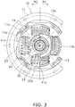
FIG. 3 is a front view of the damper device. -
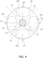
FIG. 4 is a front view of a spline hub. -
FIG. 5 is a partial enlarged view ofFIG. 2 . -
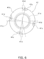
FIG. 6 is a front view of a first intermediate member. -
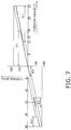
FIG. 7 is a chart showing torsional characteristics of the damper device. -
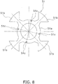
FIG. 8 is a front view of a second intermediate member. -
FIG. 9 is a partial enlarged view ofFIG. 3 . -
FIG. 10 is a schematic diagram for explaining actuation of the damper device. -
FIG. 1 is a block diagram of a vehicle in which a damper device according to a preferred embodiment of the present invention is installed. On the other hand,FIGS. 2 and3 are a cross-sectional view and a front view of the damper device, respectively. Thepresent damper device 1 is disposed between anengine 2 provided as a drive source and a power transmission device 4 including anelectric motor 3. A torque, transmitted from theengine 2, is transmitted to the power transmission device 4 through thedamper device 1, and is further transmitted to a wheel. InFIG. 2 , line O-O indicates the rotational axis of thedamper device 1. - The
damper device 1 includes an input-side rotor 10, a spline hub 20 (exemplary output-side rotor), a plurality of torsion springs 30 (exemplary damper part), a small hysteresis mechanism 40 (exemplary second friction mechanism), a large hysteresis mechanism 50 (exemplary first friction mechanism) and a hysteresis inhibiting mechanism 60 (exemplary friction control mechanism). - The input-
side rotor 10 includes adrive plate 11, aclutch plate 12 and a retainingplate 13. Theseplates side plate 10" on an as-needed basis. - The
drive plate 11 has an annular disc shape, and is fixed at the outer peripheral part thereof to an engine-side member (not shown in the drawings). Thedrive plate 11 is provided with fourfixation portions 11a on the inner peripheral edge thereof. Thefixation portions 11a are shaped to extend from the inner peripheral edge of thedrive plate 11 further radially inward, and each have a predetermined circumferential width. Additionally, thefixation portions 11a are fixed to theclutch plate 12 and the retaining plate 13 (this structure will be described in detail). - The
clutch plate 12 and the retainingplate 13, each having an annular disc shape, are disposed in axial opposition to each other. The outer peripheral part of theclutch plate 12 and that of the retainingplate 13 are processed by stamping so as to approach to each other, whereby eachplate coupling portions coupling portions fixation portions 11a of thedrive plate 11. The circumferential width of eachcoupling portion fixation portion 11a. Additionally, thefixation portions 11a are interposed between pairs ofcoupling portions clutch plate 12 and the retainingplate 13, respectively, and each triad ofportions rivets 14. Therefore, theclutch plate 12 and the retainingplate 13 are axially immovable relative to each other and are also non-rotatable relative to each other. - Each of the
clutch plate 12 and the retainingplate 13 includes fourwindow portions window portions 12b and thewindow portions 13b are provided in opposed positions. Eachwindow portion plate 13 is provided with fourengaging holes 13c in the inner peripheral part thereof. - A
first bushing 15 is disposed on theclutch plate 12 side of the inner peripheral part of the retainingplate 13. Thefirst bushing 15 is an annular member made of resin, and is provided with fourengaging protrusions 15a axially protruding from the retaining plate 13-side surface thereof. The engagingprotrusions 15a are engaged with the engagingholes 13c of the retainingplate 13, whereby thefirst bushing 15 is rotated together with the retainingplate 13. - The
spline hub 20 includes aboss 21 having a tubular shape and aflange 22 extending radially outward from the outer peripheral surface of theboss 21. Theboss 21 is inserted into a center hole of theclutch plate 12 and that of the retainingplate 13. Theboss 21 is provided with aspline hole 21a, to which a shaft (not shown in the drawings) of the power transmission device 4 is spline-coupled, in the center part thereof. Theflange 22 is disposed axially between theclutch plate 12 and the retainingplate 13. Theflange 22 is provided with fourwindow holes 22b in corresponding positions of pairs ofwindow portions clutch plate 12 and the retainingplate 13. - As shown in
FIGS. 3 and4 , theflange 22 is provided with fourstopper pawls 23 protruding radially outward from the outer peripheral edge thereof. Eachstopper pawl 23 is located in the middle of eachwindow hole 22b in the width direction of eachwindow hole 22b. Moreover, eachstopper pawl 23 is located between adjacent two of thefixation portions 11a of thedrive plate 11 in the circumferential direction. Furthermore, when thespline hub 20 is rotated relative to the input-side plate 10 at a predetermined angle, thestopper pawls 23 make contact with the pairs ofcoupling portions clutch plate 12 and the retainingplate 13, respectively. Accordingly, relative rotation between the bothmembers coupling portions stopper pawls 23 compose a stopper mechanism that restricts the input-side plate 10 and thespline hub 20 from being rotated relative to each other within a predetermined range. - Besides, each
window hole 22b is provided with acutout 24, having a predetermined width in the circumferential direction, on the inner peripheral edge thereof. Thecutout 24 is disposed on the further inner peripheral side of eachtorsion spring 30 accommodated in eachwindow hole 22b. Thecutout 24 is shaped to extend from radially inside to outside. - The torsion springs 30 are accommodated in the window holes 22b of the
spline hub 20, respectively, while being supported by pairs of thewindow portions clutch plate 12 and the retainingplate 13, respectively. Eachtorsion spring 30 is accommodated without any gaps in eachwindow hole 22b and each pair ofwindow portions torsion spring 30 makes contact at the both ends thereof with the both wall surfaces of eachwindow hole 22b and those of each pair ofwindow portions - The
small hysteresis mechanism 40 generates a small hysteresis torque (exemplary second hysteresis torque), the magnitude of which is relatively small, in the entire region of torsion angle that the input-side plate 10 and thespline hub 20 are rotated relative to each other. As shown close-up inFIG. 5 , thesmall hysteresis mechanism 40 includes a firstintermediate member 41, asecond bushing 42 and afirst cone spring 43. - As shown in
FIGS. 5 and6 , the firstintermediate member 41 is a disc-shaped member and includes atubular portion 41a, adisc portion 41b, fourcontact portions 41c and fourengaging protrusions 41d. Thetubular portion 41a is disposed on the outer peripheral surface of theboss 21 of thespline hub 20. Specifically, the inner peripheral surface of thetubular portion 41a is disposed on the outer peripheral surface of a clutch plate 12-side part of theboss 21. Thedisc portion 41b is shaped to radially extend from one end of thetubular portion 41a. Thedisc portion 41b is disposed axially between the inner peripheral part of theclutch plate 12 and theflange 22 of thespline hub 20. Eachcontact portion 41c is shaped to protrude toward the retainingplate 13 from the outer peripheral part of thedisc portion 41b. Thecontact portions 41c have the same shape. As seen in the front view, eachcontact portion 41c is made in the shape of a triangle having the apex thereof on the inner peripheral side. The fourcontact portions 41c are disposed at equal intervals in the circumferential direction. Each engagingprotrusion 41d is shaped to protrude further toward the retainingplate 13 from the middle of eachcontact portion 41c. - The
second bushing 42 is disposed on the outer peripheral surface of a retaining plate 13-side part of theboss 21 of thespline hub 20. Thesecond bushing 42 is provided with afriction portion 42a, having a disc shape, on a one-side end thereof. Thefriction portion 42a is shaped to radially extend from the one-side end of thesecond bushing 42. Thefriction portion 42a makes contact at the lateral surface thereof with theflange 22 of thespline hub 20. - The
first cone spring 43 is disposed axially between the other-side end of thesecond bushing 42 and the inner peripheral part of the retainingplate 13. Thefriction portion 42a of thesecond bushing 42 is pressed in contact with theflange 22 of thespline hub 20 by thefirst cone spring 43. - In the configuration described above, the lateral surface of the
disc portion 41b of the firstintermediate member 41 and that of theflange 22 make contact by friction with each other, whereby a hysteresis torque is generated. On the other hand, thefriction portion 42a of thesecond bushing 42 and the lateral surface of theflange 22 make contact by friction with each other, whereby a hysteresis torque is generated. The small hysteresis torque is obtained by the hysteresis torques described above. - As shown in
FIG. 7 , thelarge hysteresis mechanism 50 generates a large hysteresis torque (exemplary first hysteresis torque), the magnitude of which is greater than that of the small hysteresis torque, in the following torsional regions. - (1) When relative rotation is performed between the input-
side plate 10 and thespline hub 20 until reaching a maximum torsion angle (25 degrees) from a neutral position (0 degrees) without the relative rotation in a positive-side torsional region, the large hysteresis torque is generated in a torsional region from a first torsion angle (15 degrees) to the maximum torsion angle. - (2) When the relative rotation is performed until reaching the neutral position from the maximum torsion angle in the positive-side torsional region, the large hysteresis torque is generated in a torsional region from a second torsion angle (10 degrees) less than the first torsion angle (15 degrees) to the neutral position.
- (3) When the relative rotation is performed until reaching a maximum torsion angle (25 degrees) from the neutral position in a negative-side torsional region, the large hysteresis torque is generated in a torsional region from a third torsion angle (4 degrees) to the maximum torsion angle.
- (4) When the relative rotation is performed until reaching the neutral position from the maximum torsion angle in the negative-side torsional region, the large hysteresis torque is generated in a torsional region from a fourth torsion angle (21 degrees) greater than the third torsion angle (4 degrees) to the neutral position.
- It should be noted that "the positive-side torsional region" is a region in which the input-
side plate 10 and thespline hub 20 are displaced relative to each other when a torque is transmitted from the engine. On the other hand, "the negative-side torsional region" is a region in which the input-side plate 10 and thespline hub 20 are displaced relative to each other in a reverse direction to the displacement in the positive-side torsional region when a torque is transmitted from an output side. - The
large hysteresis mechanism 50 includes a secondintermediate member 51 and asecond cone spring 52. - As shown in
FIGS. 5 and8 , the secondintermediate member 51 includes adisc portion 51a having an annular shape and foursupport portions 51b protruding radially outward from thedisc portion 51a. Thedisc portion 51a is attached to thecontact portions 41c of the firstintermediate member 41. In more detail, thedisc portion 51a is attached to the distal end surfaces of thecontact portions 41c, while fourholes 51c, provided in thedisc portion 51a, are fitted onto the engagingprotrusions 41d provided on the distal ends of thecontact portions 41c, respectively. In other words, the secondintermediate member 51 is unitarily activated with the firstintermediate member 41. Therefore, the firstintermediate member 41 and the secondintermediate member 51 will be hereinafter referred to as "intermediate member torsion spring 30 is accommodated circumferentially between adjacent two of the foursupport portions 51b. Eachtorsion spring 30 herein makes contact at the both ends thereof with the adjacent two of thesupport portions 51b. - The
second cone spring 52 is disposed axially between thefirst bushing 15 and the inner peripheral part of the retainingplate 13. Thesecond cone spring 52 causes thefirst bushing 15 to be pressed in contact with the secondintermediate member 51, and causes theclutch plate 12 to be pressed in contact with thedisc portion 41b of the firstintermediate member 41 through the retainingplate 13. - In the configuration described above, the lateral surface of the
disc portion 51a of the secondintermediate member 51 and that of thefirst bushing 15 make contact by friction with each other, whereby a hysteresis torque is generated. On the other hand, the lateral surface of theclutch plate 12 and that of thedisc portion 41b of the firstintermediate member 41 make contact by friction with each other, whereby a hysteresis torque is generated. Here, a friction force (hysteresis torque), generated between thedisc portion 41b of the firstintermediate member 41 and theclutch plate 12, is configured to be greater than a friction force (part of the small hysteresis torque) generated between thedisc portion 41b and theflange 22. The large hysteresis torque, the magnitude of which is greater than that of the small hysteresis torque, is obtained by the hysteresis torques described above. - The
hysteresis inhibiting mechanism 60 deactivates thelarge hysteresis mechanism 50 in the following torsional regions. - (1) When the relative rotation is performed until reaching the maximum torsion angle (25 degrees) from the neutral position (0 degrees) in the positive-side torsional region, the
large hysteresis mechanism 50 is deactivated in a torsional region from the neutral position to the first torsion angle (15 degrees). - (2) When the relative rotation is performed until reaching the neutral position from the maximum torsion angle in the positive-side torsional region, the
large hysteresis mechanism 50 is deactivated in a torsional region from the maximum torsion angle to the second torsion angle (10 degrees). - (3) When the relative rotation is performed until reaching the maximum torsion angle (25 degrees) from the neutral position in the negative-side torsional region, the
large hysteresis mechanism 50 is deactivated in a torsional region from the neutral position to the third torsion angle (4 degrees). - (4) When the relative rotation is performed until reaching the neutral position from the maximum torsion angle in the negative-side torsional region, the
large hysteresis mechanism 50 is deactivated in a torsional region from the maximum torsion angle to the fourth torsion angle (21 degrees). - The
hysteresis inhibiting mechanism 60 is composed of circumferential gaps, each of which is produced between eachcontact portion 41c of the firstintermediate member 41 and eachcutout 24 of thespline hub 20. Specifically as shown inFIG. 9 , in the neutral position, a positive-side gap of angle θ1 is produced between eachcontact portion 41c and one end surface of eachcutout 24, whereas a negative-side gap of angle θ2 is produced between eachcontact portion 41c and the other end surface of eachcutout 24. - When the
spline hub 20 is rotated relative to the input-side plate 10, thelarge hysteresis mechanism 50 is not activated until either the gap of angle θ1 or that of angle θ2 becomes "0". In other words, until eachcontact portion 41c of the firstintermediate member 41 makes contact with corresponding one of the end surfaces of eachcutout 24 of thespline hub 20, relative rotation is not made not only between the secondintermediate member 51 and thefirst bushing 15 but also between theclutch plate 12 and the firstintermediate member 41. Therefore, the large hysteresis torque is not generated. - A torque, outputted from the engine, is transmitted to the power transmission device 4 including the
electric motor 3 through thedamper device 1, and is then transmitted to the wheel. In thedamper device 1, the torque inputted thereto from the engine is transmitted from the input-side plate 10 to thespline hub 20 through the torsion springs 30, and is outputted to the shaft of the power transmission device 4 that is spline-coupled to thespline hub 20. - In this torque transmission, the input-
side plate 10 and thespline hub 20 are rotated relative to each other, and the torsion springs 30 are repeatedly compressed. On the other hand, simultaneously at this time, the small hysteresis torque and the large hysteresis torque are generated by thesmall hysteresis mechanism 40 and thelarge hysteresis mechanism 50, respectively (this will be described below in detail). As a result, torsional vibration is absorbed and attenuated in thedamper device 1. - Furthermore, when the torsion angle between the input-
side plate 10 and thespline hub 20 gets larger, eachstopper pawl 23 of thespline hub 20 collides against each pair ofcoupling portions clutch plate 12 and the retainingplate 13 in due course. Accordingly, relative rotation between the bothmembers - In the positive-side torsional region corresponding to a condition that a torque is inputted from the engine, the
spline hub 20 is rotated relative to the input-side plate 10 to an R1 side (seeFIG. 3 ). Torsional characteristics will be hereinafter explained with reference to the schematic diagram ofFIG. 10 and a torsional characteristic diagram ofFIG. 7 . - As shown in
FIG. 7 and stages (a), (b) and (a-b) ofFIG. 10 , in a torsional region corresponding to an angular range θ1 from the neutral position (0 degrees) to the first torsion angle (15 degrees), only thesmall hysteresis mechanism 40 is activated, whereby only the small hysteresis torque is generated. Specifically, until the end surface of eachcutout 24 of thespline hub 20 makes contact with eachcontact portion 41c of the firstintermediate member 41, thespline hub 20 is rotated relative to not only theclutch plate 12 and the retainingplate 13 but also theintermediate members clutch plate 12 and the retainingplate 13 and theintermediate members disc portion 41b of the firstintermediate member 41 and theflange 22 make contact by friction with each other, while thesecond bushing 42 and theflange 22 make contact by friction with each other. Accordingly, the small hysteresis torque is obtained. - As shown in
FIG. 7 and stages (b), (c) and (b-c) ofFIG. 10 , when the torsion angle reaches the first torsion angle (15 degrees), the end surface of eachcutout 24 of thespline hub 20 makes contact with eachcontact portion 41c of the firstintermediate member 41. Because of this, in the torsional region from the first torsion angle (15 degrees) to the maximum torsion angle (25 degrees), theintermediate members spline hub 20. In other words, thespline hub 20 and theintermediate members clutch plate 12 and the retainingplate 13. Here, thelarge hysteresis mechanism 50 is activated together with thesmall hysteresis mechanism 40. In thelarge hysteresis mechanism 50, thedisc portion 51a of the secondintermediate member 51 and thefirst bushing 15 make contact by friction with each other, while theclutch plate 12 and thedisc portion 41b of the firstintermediate member 41 make contact by friction with each other. Accordingly, the large hysteresis torque greater than the small hysteresis torque is obtained. - As shown in
FIG. 7 and stages (c), (d) and (c-d) ofFIG. 10 , in a torsional region corresponding to an angular range θ1 from the maximum torsion angle (25 degrees) to the second torsion angle (10 degrees), only the small hysteresis torque is generated. Specifically, the end surface of eachcutout 24 of thespline hub 20 is separated from eachcontact portion 41c of the firstintermediate member 41, and hence, thespline hub 20 is rotated relative to not only theclutch plate 12 and the retainingplate 13 but also theintermediate members intermediate members - As shown in
FIG. 7 and stages (d), (e) and (d-e) ofFIG. 10 , when the torsion angle reaches the second torsion angle (10 degrees), eachtorsion spring 30, restored to the pre-compressed state thereof, makes contact at the end surface thereof with eachsupport portion 51b of the secondintermediate member 51. Because of this, in the torsional region from the second torsion angle (10 degrees) to the neutral position, theintermediate members spline hub 20. In other words, thespline hub 20 and theintermediate members clutch plate 12 and the retainingplate 13. Therefore, the large hysteresis torque is obtained. - According to the
damper device 1 having the torsional characteristics described above, in the positive-side torsional region, only the small hysteresis torque is constantly obtained in any of the angular ranges θ1 (15 degrees). In other words, thelarge hysteresis mechanism 50 is not activated unless fluctuations in the torque exceed a range corresponding to a torsion angle θ1 (the deactivation angular range.) Besides, each angular range θ1, in which the small hysteresis torque is obtained, is wider than an angular range (10 degrees) in which the large hysteresis torque us obtained. Because of this, small-amplitude vibration can be effectively inhibited in normal operation, and simultaneously, drivability can be enhanced. Moreover, the large hysteresis torque is obtained before the relative rotation reaches the maximum torsion angle and in the vicinity of the neutral position. Because of this, relatively large-amplitude vibration can be effectively inhibited when the engine is started by the electric motor, when the engine is stopped, or when such vibration is inputted from the output side. Furthermore, shock can be inhibited from being applied to the stopper mechanism composed of theconstituent elements torsion spring 30 is configured to be switched between the bothplates flange 22. In this case, the large hysteresis torque is generated, whereby it is possible to inhibit shock occurring in switching of the contacted portions. - Actuation made in characteristics exerted in the negative-side torsional region is basically the same as that made in the characteristics exerted in the positive-side torsional region, although angular settings for the characteristics exerted in the negative-side torsional region are only different from those for the characteristics exerted in the positive-side torsional region. Specifically, in the negative-side torsional region, the small hysteresis torque is obtained in a torsional region from the neutral position to the third torsion angle (4 degrees) and a torsional region from the maximum torsion angle (25 degrees) to the fourth torsion angle (21 degrees). On the other hand, the large hysteresis torque is obtained in a torsional region from the third torsion angle (4 degrees) to the maximum torsion angle (25 degrees) and a torsional region from the fourth torsion angle (21 degrees) to the neutral position.
- Here, contrarily to the positive-side torsional region, the angular range (17 degrees), in which the large hysteresis torque is generated, is wider than the angular range θ2 (4 degrees) in which the small hysteresis torque is generated. Because of this, it is possible to effectively inhibit large-amplitude vibration inputted from the output side such as the wheel. Additionally, vibration inputted from a vibration source disposed on the output side and resonance attributed to an electric motor having a large amount of inertia can be set outside a rotational speed range normally used. Because of this, excessive torque can be inhibited from being transmitted to the input side in an operating condition normally used. Therefore, the entire drivetrain can be protected, and besides, compactness in component is enabled. Also, resonance attributed to vibration applied from the output side can be inhibited.
- The present invention is not limited to the preferred embodiment described above, and a variety of changes or modifications can be made without departing from the scope of the present invention.
- (a) In the aforementioned preferred embodiment, the first and second
intermediate members - (b) In the aforementioned preferred embodiment, the first
intermediate member 41 is provided with thecontact portions 41c, whereas theflange 22 is provided with thecutouts 24. However, the first intermediate member may be provided with cutouts, whereas the flange may be provided with contact portions that are inserted into the cutouts of the first intermediate member, respectively. - (c) In the aforementioned preferred embodiment, the first intermediate member and the clutch plate are configured to directly make contact by friction with each other. However, the first intermediate member may be provided with a friction member fixed thereto, and may be configured to make contact at the friction member with the clutch plate.
- (d) The magnitudes of hysteresis torques obtained by the small hysteresis mechanism and the large hysteresis mechanisms and the angular ranges in which the respective hysteresis torques are generated are exemplary only.
-
- 1
- Damper device
- 2
- Engine
- 3
- Electric motor
- 12
- Clutch plate (first plate, input-side rotor)
- 13
- Retaining plate (second plate, input-side rotor)
- 20
- Spline Hub (output-side rotor)
- 22
- Flange
- 24
- Cutout
- 30
- Torsion Spring (damper part)
- 40
- Small hysteresis mechanism (second friction mechanism)
- 41
- First intermediate member
- 41b
- Disc portion
- 41c
- Contact portion
- 50
- Large hysteresis mechanism (first friction mechanism)
- 51
- Second intermediate member
- 51a
- Disc portion
- 52
- Second cone spring
- 60
- Hysteresis inhibiting mechanism (friction control mechanism)
Claims (11)
- A damper device for a vehicle transmitting a torque from a drive source to an output side therethrough, the damper device comprising:an input-side rotor;an output-side rotor rotatable relative to the input-side rotor; anda damper part adapted to elastically couple the input-side rotor and the output-side rotor in a rotational direction;characterized by1.1 a first friction mechanism adapted to generate a first hysteresis torque in relative rotation between the input-side rotor and the output-side rotor; and
a friction control mechanism adapted to control actuation of the first friction mechanism, wherein
in a positive-side torsional region in which the torque is transmitted from the drive source, when the relative rotation is performed until reaching a maximum torsion angle from a neutral position without the relative rotation, the friction control mechanism deactivates the first friction mechanism until the relative rotation reaches a first torsion angle from the neutral position, the friction control mechanism activating the first friction mechanism until the relative rotation reaches the maximum torsion angle from the first torsion angle, and when the relative rotation is performed until reaching the neutral position from the maximum torsion angle, the friction control mechanism deactivates the first friction mechanism until the relative rotation reaches a second torsion angle less than the first torsion angle from the maximum torsion angle, the friction control mechanism activating the first friction mechanism until the relative rotation reaches the neutral position from the second torsion angle;
and/or1.2 a friction mechanism adapted to generate a hysteresis torque in relative rotation between the input-side rotor and the output-side rotor, wherein
the friction mechanism includes a small friction mechanism and a large friction mechanism, the small friction mechanism adapted to generate a small hysteresis torque, the large friction mechanism generating a large hysteresis torque greater than the small hysteresis torque,
in a positive-side torsional region in which the torque is transmitted from the drive source, the small friction mechanism generates the small hysteresis torque within a first angular range in which the relative rotation is performed until reaching a first torsion angle from a neutral position without the relative rotation, and
in the positive-side torsional region, the large friction mechanism generates the large hysteresis torque greater than the small hysteresis torque within a second angular range in which the relative rotation is performed until reaching a maximum torsion angle from the first torsion angle, the second angular range narrower than the first angular range. - The damper device according to claim 1, wherein a deactivation angular range from the neutral position to the first torsion angle and a deactivation angular range from the maximum torsion angle to the second torsion angle are equal in magnitude.
- The damper device according to claim 2, wherein each of the deactivation angular ranges is wider than each of an activation angular range from the first torsion angle to the maximum torsion angle and an activation angular range from the second torsion angle to the neutral position.
- The damper device according to claim 2 or 3, wherein the friction control mechanism deactivates the first friction mechanism within a range that fluctuations in the torque transmitted from the drive source correspond to the deactivation angular ranges in an entire angular range between the neutral position and the maximum torsion angle.
- The damper device according to any of claims 1 to 4, further comprising:
a second friction mechanism adapted to generate a second hysteresis torque less than the first hysteresis torque in an entire angular range in which the relative rotation between the input-side rotor and the output-side rotor is performed. - The damper device according to any of claims 1 to 5, wherein in a negative-side torsional region in which a torque is transmitted from the output side,when the relative rotation is performed until reaching a maximum torsion angle from the neutral position, the friction control mechanism deactivates the first friction mechanism until the relative rotation reaches a third torsion angle from the neutral position, the friction control mechanism activating the first friction mechanism until the relative rotation reaches the maximum torsion angle from the third torsion angle, andwhen the relative rotation is performed until reaching the neutral position from the maximum torsion angle, the friction control mechanism deactivates the first friction mechanism until the relative rotation reaches a fourth torsion angle greater than the third torsion angle from the maximum torsion angle, the friction control mechanism activating the first friction mechanism until the relative rotation reaches the neutral position from the fourth torsion angle.
- The damper device according to any of claims 1 to 6, whereinthe drive source is an engine, andan electric motor for starting the engine and driving the vehicle is disposed on the output side.
- The damper device according to any of claims 1 to 7, whereinthe input-side rotor includes a first plate and a second plate, the first and second plates disposed in axial opposition to each other at a predetermined interval, the first and second plates fixed to each other so as to be axially immovable from each other and be non-rotatable relative to each other,the output-side rotor includes a flange, the flange being disposed to be interposed between the first and second plates, andthe first friction mechanism is disposed axially between the flange and at least one of the first and second plates.
- The damper device according to any of claims 1 to 8, wherein the first friction mechanism includesa friction plate rotated together with the output-side rotor within a predetermined angular range, the friction plate capable of making contact by friction with the input-side rotor, andan urging member adapted to cause the friction plate and the input-side rotor to be pressed in contact with each other.
- The damper device according to claim 9, wherein
the friction control mechanism includesa cutout provided in one of the output-side rotor and the friction plate, the cutout extending within a predetermined angular range in a circumferential direction, anda contact portion provided in the other of the output-side rotor and the friction plate, the contact portion disposed in the cutout at a predetermined gap therefrom, andthe friction plate is rotatable relative to the output-side rotor within a range of the predetermined gap. - The damper device according to any of the claims 1 to 10, wherein
in a negative-side torsional region in which a torque is transmitted from the output side, the small friction mechanism generates the small hysteresis torque within a third angular range in which the relative rotation is performed until reaching a third torsion angle from the neutral position, and
in the negative-side torsional region in which the torque is transmitted from the output side, the large friction mechanism generates the large hysteresis torque to be greater than the small hysteresis torque within a fourth angular range in which the relative rotation is performed until reaching a maximum torsion angle from the third torsion angle, the fourth angular range wider than the third angular range.
Applications Claiming Priority (1)
| Application Number | Priority Date | Filing Date | Title |
|---|---|---|---|
| JP2019018510A JP7198103B2 (en) | 2019-02-05 | 2019-02-05 | damper device |
Publications (2)
| Publication Number | Publication Date |
|---|---|
| EP3693631A1 true EP3693631A1 (en) | 2020-08-12 |
| EP3693631B1 EP3693631B1 (en) | 2026-04-15 |
Family
ID=69191908
Family Applications (1)
| Application Number | Title | Priority Date | Filing Date |
|---|---|---|---|
| EP20153503.6A Active EP3693631B1 (en) | 2019-02-05 | 2020-01-24 | Damper device |
Country Status (4)
| Country | Link |
|---|---|
| US (1) | US10968978B2 (en) |
| EP (1) | EP3693631B1 (en) |
| JP (1) | JP7198103B2 (en) |
| CN (1) | CN111520436A (en) |
Families Citing this family (5)
| Publication number | Priority date | Publication date | Assignee | Title |
|---|---|---|---|---|
| FR3094432B1 (en) * | 2019-03-29 | 2022-06-03 | Valeo Embrayages | Torsion damper and clutch disc. |
| JP7473420B2 (en) * | 2020-08-20 | 2024-04-23 | 株式会社エクセディ | Damper Device |
| JP7473419B2 (en) * | 2020-08-20 | 2024-04-23 | 株式会社エクセディ | Damper Device |
| JP7797195B2 (en) * | 2021-12-27 | 2026-01-13 | 株式会社エクセディ | Damper Device |
| JP2024029797A (en) * | 2022-08-23 | 2024-03-07 | ヤマハ発動機株式会社 | Electric power unit and straddle-type vehicle equipped with it |
Citations (5)
| Publication number | Priority date | Publication date | Assignee | Title |
|---|---|---|---|---|
| US4645053A (en) * | 1984-07-05 | 1987-02-24 | Kabushiki Kaisha Daikin Seisakusho | Damper disc |
| US5205389A (en) * | 1990-10-06 | 1993-04-27 | Fichtel & Sachs Ag | Clutch disk |
| US20070191120A1 (en) * | 2006-02-16 | 2007-08-16 | Aisin Seiki Kabushiki Kaisha | Torque fluctuation absorber |
| JP2014070713A (en) | 2012-10-01 | 2014-04-21 | Toyota Motor Corp | Damper device of vehicle |
| US20170363150A1 (en) * | 2016-06-16 | 2017-12-21 | Zf Friedrichshafen Ag | Torsional Damper With Angular-Dependent Friction Damping Device |
Family Cites Families (14)
| Publication number | Priority date | Publication date | Assignee | Title |
|---|---|---|---|---|
| JPS56113845A (en) * | 1980-02-06 | 1981-09-08 | Daikin Mfg Co Ltd | Damper disk |
| JPS59194637U (en) * | 1983-06-09 | 1984-12-24 | 株式会社 大金製作所 | damper disc |
| JPS60172728A (en) * | 1984-02-17 | 1985-09-06 | Daikin Mfg Co Ltd | Assembly of damper disc |
| JPH11270629A (en) * | 1998-03-20 | 1999-10-05 | Unisia Jecs Corp | Torsion damper |
| DE19920397A1 (en) * | 1998-05-07 | 1999-11-11 | Luk Lamellen & Kupplungsbau | Automotive clutch plate torsion damper has reduced stiffness in one sector |
| US6270417B1 (en) * | 1998-07-17 | 2001-08-07 | Exedy Corporation | Damper mechanism |
| JP3943849B2 (en) * | 2001-03-09 | 2007-07-11 | 株式会社エクセディ | Damper mechanism |
| JP4298992B2 (en) * | 2002-06-07 | 2009-07-22 | 株式会社エクセディ | Damper disk assembly |
| JP2005207553A (en) * | 2004-01-26 | 2005-08-04 | Exedy Corp | Flywheel assembly unit |
| JP4013259B2 (en) * | 2004-07-12 | 2007-11-28 | アイシン・エィ・ダブリュ株式会社 | Power transmission device for hybrid type vehicle |
| EP2672141A4 (en) * | 2011-02-04 | 2014-12-17 | Toyota Motor Co Ltd | TORSION VIBRATION DAMPING DEVICE |
| EP3124827B1 (en) * | 2014-03-24 | 2020-01-15 | Aisin Seiki Kabushiki Kaisha | Damper device |
| FR3039235B1 (en) * | 2015-07-24 | 2019-04-12 | Valeo Embrayages | VIBRATION DAMPING DEVICE |
| EP3336380B1 (en) * | 2016-12-14 | 2020-04-15 | Aisin Seiki Kabushiki Kaisha | Torque fluctuation absorbing apparatus |
-
2019
- 2019-02-05 JP JP2019018510A patent/JP7198103B2/en active Active
- 2019-12-04 US US16/703,217 patent/US10968978B2/en active Active
-
2020
- 2020-01-24 EP EP20153503.6A patent/EP3693631B1/en active Active
- 2020-02-03 CN CN202010079163.9A patent/CN111520436A/en active Pending
Patent Citations (5)
| Publication number | Priority date | Publication date | Assignee | Title |
|---|---|---|---|---|
| US4645053A (en) * | 1984-07-05 | 1987-02-24 | Kabushiki Kaisha Daikin Seisakusho | Damper disc |
| US5205389A (en) * | 1990-10-06 | 1993-04-27 | Fichtel & Sachs Ag | Clutch disk |
| US20070191120A1 (en) * | 2006-02-16 | 2007-08-16 | Aisin Seiki Kabushiki Kaisha | Torque fluctuation absorber |
| JP2014070713A (en) | 2012-10-01 | 2014-04-21 | Toyota Motor Corp | Damper device of vehicle |
| US20170363150A1 (en) * | 2016-06-16 | 2017-12-21 | Zf Friedrichshafen Ag | Torsional Damper With Angular-Dependent Friction Damping Device |
Also Published As
| Publication number | Publication date |
|---|---|
| US10968978B2 (en) | 2021-04-06 |
| CN111520436A (en) | 2020-08-11 |
| EP3693631B1 (en) | 2026-04-15 |
| JP2020125806A (en) | 2020-08-20 |
| US20200248779A1 (en) | 2020-08-06 |
| JP7198103B2 (en) | 2022-12-28 |
Similar Documents
| Publication | Publication Date | Title |
|---|---|---|
| EP3693631B1 (en) | Damper device | |
| US9964158B2 (en) | Damper disk assembly | |
| US11841061B2 (en) | Damper device | |
| US10161459B2 (en) | Damper disc assembly | |
| US12049937B2 (en) | Damper device | |
| JP2012127410A (en) | Damper device with torque limiter | |
| US11965576B2 (en) | Damper device | |
| JP3943850B2 (en) | Damper mechanism | |
| EP3699453B1 (en) | Damper disc assembly | |
| CN114060462B (en) | Vibration damping device | |
| US20230243389A1 (en) | Damper device | |
| JP4015774B2 (en) | Damper mechanism and damper disk assembly | |
| CN113309817B (en) | Vibration damper | |
| JP4109787B2 (en) | Damper mechanism | |
| US12392380B2 (en) | Damper device | |
| JP3675644B2 (en) | Damper mechanism | |
| US20260126084A1 (en) | Power transmission device | |
| US12422002B2 (en) | Damper device | |
| JP2001173720A (en) | Damper mechanism and damper disc assembly | |
| JP2021134834A (en) | Spring seat and damper device | |
| JPH11280785A (en) | Damper mechanism |
Legal Events
| Date | Code | Title | Description |
|---|---|---|---|
| PUAI | Public reference made under article 153(3) epc to a published international application that has entered the european phase |
Free format text: ORIGINAL CODE: 0009012 |
|
| STAA | Information on the status of an ep patent application or granted ep patent |
Free format text: STATUS: THE APPLICATION HAS BEEN PUBLISHED |
|
| AK | Designated contracting states |
Kind code of ref document: A1 Designated state(s): AL AT BE BG CH CY CZ DE DK EE ES FI FR GB GR HR HU IE IS IT LI LT LU LV MC MK MT NL NO PL PT RO RS SE SI SK SM TR |
|
| AX | Request for extension of the european patent |
Extension state: BA ME |
|
| STAA | Information on the status of an ep patent application or granted ep patent |
Free format text: STATUS: REQUEST FOR EXAMINATION WAS MADE |
|
| 17P | Request for examination filed |
Effective date: 20201218 |
|
| RBV | Designated contracting states (corrected) |
Designated state(s): AL AT BE BG CH CY CZ DE DK EE ES FI FR GB GR HR HU IE IS IT LI LT LU LV MC MK MT NL NO PL PT RO RS SE SI SK SM TR |
|
| STAA | Information on the status of an ep patent application or granted ep patent |
Free format text: STATUS: EXAMINATION IS IN PROGRESS |
|
| 17Q | First examination report despatched |
Effective date: 20220926 |
|
| GRAP | Despatch of communication of intention to grant a patent |
Free format text: ORIGINAL CODE: EPIDOSNIGR1 |
|
| STAA | Information on the status of an ep patent application or granted ep patent |
Free format text: STATUS: GRANT OF PATENT IS INTENDED |
|
| INTG | Intention to grant announced |
Effective date: 20251110 |
|
| GRAS | Grant fee paid |
Free format text: ORIGINAL CODE: EPIDOSNIGR3 |
|
| GRAA | (expected) grant |
Free format text: ORIGINAL CODE: 0009210 |
|
| STAA | Information on the status of an ep patent application or granted ep patent |
Free format text: STATUS: THE PATENT HAS BEEN GRANTED |
|
| AK | Designated contracting states |
Kind code of ref document: B1 Designated state(s): AL AT BE BG CH CY CZ DE DK EE ES FI FR GB GR HR HU IE IS IT LI LT LU LV MC MK MT NL NO PL PT RO RS SE SI SK SM TR |
|
| REG | Reference to a national code |
Ref country code: CH Ref legal event code: F10 Free format text: ST27 STATUS EVENT CODE: U-0-0-F10-F00 (AS PROVIDED BY THE NATIONAL OFFICE) Effective date: 20260415 |