EP3693599A1 - Fuel pump and inlet valve assembly thereof - Google Patents
Fuel pump and inlet valve assembly thereof Download PDFInfo
- Publication number
- EP3693599A1 EP3693599A1 EP20155561.2A EP20155561A EP3693599A1 EP 3693599 A1 EP3693599 A1 EP 3693599A1 EP 20155561 A EP20155561 A EP 20155561A EP 3693599 A1 EP3693599 A1 EP 3693599A1
- Authority
- EP
- European Patent Office
- Prior art keywords
- inlet valve
- bore
- fuel pump
- pumping chamber
- fuel
- Prior art date
- Legal status (The legal status is an assumption and is not a legal conclusion. Google has not performed a legal analysis and makes no representation as to the accuracy of the status listed.)
- Granted
Links
Images



Classifications
-
- F—MECHANICAL ENGINEERING; LIGHTING; HEATING; WEAPONS; BLASTING
- F02—COMBUSTION ENGINES; HOT-GAS OR COMBUSTION-PRODUCT ENGINE PLANTS
- F02M—SUPPLYING COMBUSTION ENGINES IN GENERAL WITH COMBUSTIBLE MIXTURES OR CONSTITUENTS THEREOF
- F02M59/00—Pumps specially adapted for fuel-injection and not provided for in groups F02M39/00 -F02M57/00, e.g. rotary cylinder-block type of pumps
- F02M59/20—Varying fuel delivery in quantity or timing
- F02M59/34—Varying fuel delivery in quantity or timing by throttling of passages to pumping elements or of overflow passages, e.g. throttling by means of a pressure-controlled sliding valve having liquid stop or abutment
-
- F—MECHANICAL ENGINEERING; LIGHTING; HEATING; WEAPONS; BLASTING
- F02—COMBUSTION ENGINES; HOT-GAS OR COMBUSTION-PRODUCT ENGINE PLANTS
- F02M—SUPPLYING COMBUSTION ENGINES IN GENERAL WITH COMBUSTIBLE MIXTURES OR CONSTITUENTS THEREOF
- F02M59/00—Pumps specially adapted for fuel-injection and not provided for in groups F02M39/00 -F02M57/00, e.g. rotary cylinder-block type of pumps
- F02M59/44—Details, components parts, or accessories not provided for in, or of interest apart from, the apparatus of groups F02M59/02 - F02M59/42; Pumps having transducers, e.g. to measure displacement of pump rack or piston
- F02M59/46—Valves
-
- F—MECHANICAL ENGINEERING; LIGHTING; HEATING; WEAPONS; BLASTING
- F02—COMBUSTION ENGINES; HOT-GAS OR COMBUSTION-PRODUCT ENGINE PLANTS
- F02M—SUPPLYING COMBUSTION ENGINES IN GENERAL WITH COMBUSTIBLE MIXTURES OR CONSTITUENTS THEREOF
- F02M59/00—Pumps specially adapted for fuel-injection and not provided for in groups F02M39/00 -F02M57/00, e.g. rotary cylinder-block type of pumps
- F02M59/02—Pumps specially adapted for fuel-injection and not provided for in groups F02M39/00 -F02M57/00, e.g. rotary cylinder-block type of pumps of reciprocating-piston or reciprocating-cylinder type
- F02M59/025—Pumps specially adapted for fuel-injection and not provided for in groups F02M39/00 -F02M57/00, e.g. rotary cylinder-block type of pumps of reciprocating-piston or reciprocating-cylinder type characterised by a single piston
-
- F—MECHANICAL ENGINEERING; LIGHTING; HEATING; WEAPONS; BLASTING
- F02—COMBUSTION ENGINES; HOT-GAS OR COMBUSTION-PRODUCT ENGINE PLANTS
- F02M—SUPPLYING COMBUSTION ENGINES IN GENERAL WITH COMBUSTIBLE MIXTURES OR CONSTITUENTS THEREOF
- F02M59/00—Pumps specially adapted for fuel-injection and not provided for in groups F02M39/00 -F02M57/00, e.g. rotary cylinder-block type of pumps
- F02M59/20—Varying fuel delivery in quantity or timing
- F02M59/36—Varying fuel delivery in quantity or timing by variably-timed valves controlling fuel passages to pumping elements or overflow passages
- F02M59/366—Valves being actuated electrically
-
- F—MECHANICAL ENGINEERING; LIGHTING; HEATING; WEAPONS; BLASTING
- F02—COMBUSTION ENGINES; HOT-GAS OR COMBUSTION-PRODUCT ENGINE PLANTS
- F02M—SUPPLYING COMBUSTION ENGINES IN GENERAL WITH COMBUSTIBLE MIXTURES OR CONSTITUENTS THEREOF
- F02M59/00—Pumps specially adapted for fuel-injection and not provided for in groups F02M39/00 -F02M57/00, e.g. rotary cylinder-block type of pumps
- F02M59/20—Varying fuel delivery in quantity or timing
- F02M59/36—Varying fuel delivery in quantity or timing by variably-timed valves controlling fuel passages to pumping elements or overflow passages
- F02M59/366—Valves being actuated electrically
- F02M59/368—Pump inlet valves being closed when actuated
-
- F—MECHANICAL ENGINEERING; LIGHTING; HEATING; WEAPONS; BLASTING
- F02—COMBUSTION ENGINES; HOT-GAS OR COMBUSTION-PRODUCT ENGINE PLANTS
- F02M—SUPPLYING COMBUSTION ENGINES IN GENERAL WITH COMBUSTIBLE MIXTURES OR CONSTITUENTS THEREOF
- F02M59/00—Pumps specially adapted for fuel-injection and not provided for in groups F02M39/00 -F02M57/00, e.g. rotary cylinder-block type of pumps
- F02M59/44—Details, components parts, or accessories not provided for in, or of interest apart from, the apparatus of groups F02M59/02 - F02M59/42; Pumps having transducers, e.g. to measure displacement of pump rack or piston
- F02M59/46—Valves
- F02M59/464—Inlet valves of the check valve type
-
- F—MECHANICAL ENGINEERING; LIGHTING; HEATING; WEAPONS; BLASTING
- F02—COMBUSTION ENGINES; HOT-GAS OR COMBUSTION-PRODUCT ENGINE PLANTS
- F02M—SUPPLYING COMBUSTION ENGINES IN GENERAL WITH COMBUSTIBLE MIXTURES OR CONSTITUENTS THEREOF
- F02M63/00—Other fuel-injection apparatus having pertinent characteristics not provided for in groups F02M39/00 - F02M57/00 or F02M67/00; Details, component parts, or accessories of fuel-injection apparatus, not provided for in, or of interest apart from, the apparatus of groups F02M39/00 - F02M61/00 or F02M67/00; Combination of fuel pump with other devices, e.g. lubricating oil pump
- F02M63/0012—Valves
- F02M63/0031—Valves characterized by the type of valves, e.g. special valve member details, valve seat details, valve housing details
- F02M63/0056—Throttling valves, e.g. having variable opening positions throttling the flow
-
- F—MECHANICAL ENGINEERING; LIGHTING; HEATING; WEAPONS; BLASTING
- F04—POSITIVE - DISPLACEMENT MACHINES FOR LIQUIDS; PUMPS FOR LIQUIDS OR ELASTIC FLUIDS
- F04B—POSITIVE-DISPLACEMENT MACHINES FOR LIQUIDS; PUMPS
- F04B1/00—Multi-cylinder machines or pumps characterised by number or arrangement of cylinders
- F04B1/04—Multi-cylinder machines or pumps characterised by number or arrangement of cylinders having cylinders in star- or fan-arrangement
- F04B1/0404—Details or component parts
- F04B1/0452—Distribution members, e.g. valves
-
- F—MECHANICAL ENGINEERING; LIGHTING; HEATING; WEAPONS; BLASTING
- F04—POSITIVE - DISPLACEMENT MACHINES FOR LIQUIDS; PUMPS FOR LIQUIDS OR ELASTIC FLUIDS
- F04B—POSITIVE-DISPLACEMENT MACHINES FOR LIQUIDS; PUMPS
- F04B17/00—Pumps characterised by combination with, or adaptation to, specific driving engines or motors
- F04B17/05—Pumps characterised by combination with, or adaptation to, specific driving engines or motors driven by internal-combustion engines
-
- F—MECHANICAL ENGINEERING; LIGHTING; HEATING; WEAPONS; BLASTING
- F16—ENGINEERING ELEMENTS AND UNITS; GENERAL MEASURES FOR PRODUCING AND MAINTAINING EFFECTIVE FUNCTIONING OF MACHINES OR INSTALLATIONS; THERMAL INSULATION IN GENERAL
- F16K—VALVES; TAPS; COCKS; ACTUATING-FLOATS; DEVICES FOR VENTING OR AERATING
- F16K15/00—Check valves
- F16K15/02—Check valves with guided rigid valve members
- F16K15/025—Check valves with guided rigid valve members the valve being loaded by a spring
- F16K15/026—Check valves with guided rigid valve members the valve being loaded by a spring the valve member being a movable body around which the medium flows when the valve is open
- F16K15/028—Check valves with guided rigid valve members the valve being loaded by a spring the valve member being a movable body around which the medium flows when the valve is open the valve member consisting only of a predominantly disc-shaped flat element
-
- F—MECHANICAL ENGINEERING; LIGHTING; HEATING; WEAPONS; BLASTING
- F04—POSITIVE - DISPLACEMENT MACHINES FOR LIQUIDS; PUMPS FOR LIQUIDS OR ELASTIC FLUIDS
- F04B—POSITIVE-DISPLACEMENT MACHINES FOR LIQUIDS; PUMPS
- F04B2201/00—Pump parameters
- F04B2201/06—Valve parameters
Definitions
- the present invention relates a fuel pump which supplies fuel to an internal combustion engine, and more particularly to such a fuel pump which includes an inlet valve assembly.
- GDi gasoline direct injection
- fuel from a fuel tank is supplied under relatively low pressure by a low-pressure fuel pump which is typically an electric fuel pump located within the fuel tank.
- the low-pressure fuel pump supplies the fuel to a high-pressure fuel pump which typically includes a pumping plunger which is reciprocated by a camshaft of the internal combustion engine. Reciprocation of the pumping plunger further pressurizes the fuel in order to be supplied to fuel injectors which inject the fuel directly into the combustion chambers of the internal combustion engine.
- the internal combustion is subject to varying demands for output torque.
- the mass of fuel delivered by each stroke of the pumping plunger must also be varied.
- One strategy to vary the delivery of fuel by the high-pressure fuel pump is to use a digital inlet valve which allows a full charge of fuel to enter the pumping chamber during each intake stroke, however, the digital inlet valve may be allowed to remain open during a portion of a compression stroke of the pumping plunger to allow some fuel to spill back toward the source.
- the digital inlet valve is closed during the remainder of the compression stroke, the fuel is pressurized and the pressurized fuel is supplied to the fuel injectors. Examples of such an arrangement are disclosed in United States Patent No.
- a fuel pump includes a fuel pump housing with a pumping chamber defined therein, the fuel pump housing having an inlet valve bore which is connectable to a source of fuel via a pump housing inlet passage, the inlet valve bore extending along an inlet valve bore axis and being stepped such that the inlet valve bore includes a shoulder which is traverse to the inlet valve bore axis; a pumping plunger which reciprocates within a plunger bore along a plunger bore axis such that an intake stroke of the pumping plunger increases volume of the pumping chamber and a compression stroke of the pumping plunger decreases volume of the pumping chamber; and an inlet valve assembly.
- the inlet valve assembly includes a valve seat with a valve seat flow passage extending therethrough, the valve seat being located within the inlet valve bore such that the valve seat abuts the shoulder and is urged toward the shoulder by pressure within the pumping chamber during the compression stroke; and a valve member which is moveable between 1) an unseated position which provides fluid communication through the valve seat flow passage and 2) a seated position which prevents fluid communication through the valve seat flow passage.
- the shoulder may face toward the pumping chamber.
- the inlet valve bore may include an inlet valve bore first portion which is proximal to the pumping chamber and which has a first diameter; the inlet valve bore may include an inlet valve bore second portion which is distal from the pumping chamber and which has a second diameter that is less than the first diameter.
- the shoulder may join the inlet valve bore first portion and the inlet valve bore second portion.
- the fuel pump housing may include a second bore extending therethrough from the pumping chamber such that the second bore is sized to allow passage of the valve seat therethrough to accommodate installation of the valve seat into the inlet valve bore first portion through the second bore.
- the second bore may be diametrically opposed to the inlet valve bore.
- the inlet valve bore may be centered about the inlet valve bore axis; and the second bore may be centered about the inlet valve bore axis.
- the fuel pump may further comprise an outlet valve assembly which is located within the second bore, the outlet valve assembly allowing pressurized fuel to flow out of the pumping chamber and preventing fuel from flowing back into the pumping chamber.
- the inlet valve bore may be centered about the inlet valve bore axis; and the second bore may be centered about the inlet valve bore axis.
- the valve seat may be fixed within the inlet valve bore first portion by interference fit such that an outer periphery of the valve seat is sealed to an inner periphery of the inlet valve bore first portion.
- the shoulder may face toward the pumping chamber.
- valve seat supported by the shoulder of the fuel pump housing
- the high cyclic load resulting from the pressurization of fuel in the pumping chamber is carried directly by the fuel pump housing rather than by secondary means such as interference fit, threaded connections, welding, and threaded fasteners as is currently used in the prior art. In this way, the number of components and processes is reduced, thereby reducing cost and providing a more robust connection.
- Fuel system 10 for an internal combustion engine 12 is shown in schematic form.
- Fuel system 10 generally includes a fuel tank 14 which holds a volume of fuel to be supplied to internal combustion engine 12 for operation thereof; a plurality of fuel injectors 16 which inject fuel directly into respective combustion chambers (not shown) of internal combustion engine 12; a low-pressure fuel pump 18; and a high-pressure fuel pump 20 where the low-pressure fuel pump 18 draws fuel from fuel tank 14 and elevates the pressure of the fuel for delivery to high-pressure fuel pump 20 where the high-pressure fuel pump 20 further elevates the pressure of the fuel for delivery to fuel injectors 16.
- low-pressure fuel pump 18 may elevate the pressure of the fuel to about 500 kPa or less and high-pressure fuel pump 20 may elevate the pressure of the fuel to above about 14 MPa and may be about 35MPa depending on the operational needs of internal combustion engine 12. While four fuel injectors 16 have been illustrated, it should be understood that a lesser or greater number of fuel injectors 16 may be provided.
- low-pressure fuel pump 18 may be provided within fuel tank 14, however low-pressure fuel pump 18 may alternatively be provided outside of fuel tank 14.
- Low-pressure fuel pump 18 may be an electric fuel pump as are well known to a practitioner of ordinary skill in the art.
- a low-pressure fuel supply passage 22 provides fluid communication from low-pressure fuel pump 18 to high-pressure fuel pump 20.
- a fuel pressure regulator 24 may be provided such that fuel pressure regulator 24 maintains a substantially uniform pressure within low-pressure fuel supply passage 22 by returning a portion of the fuel supplied by low-pressure fuel pump 18 to fuel tank 14 through a fuel return passage 26. While fuel pressure regulator 24 has been illustrated in low-pressure fuel supply passage 22 outside of fuel tank 14, it should be understood that fuel pressure regulator 24 may be located within fuel tank 14 and may be integrated with low-pressure fuel pump 18.
- high-pressure fuel pump 20 includes a fuel pump housing 28 which includes a plunger bore 30 which extends along, and is centered about, a plunger bore axis 32.
- plunger bore 30 may be defined by a combination of an insert and directly by fuel pump housing 28 but may alternatively be formed only, and directly by, fuel pump housing 28.
- High-pressure fuel pump 20 also includes a pumping plunger 34 which is located within plunger bore 30 and reciprocates within plunger bore 30 along plunger bore axis 32 based on input from a rotating camshaft 36 of internal combustion engine 12 (shown only in FIG. 1 ).
- a pumping chamber 38 is defined within fuel pump housing 28, and more specifically, pumping chamber 38 is defined by plunger bore 30 and pumping plunger 34.
- An inlet valve assembly 40 of high-pressure fuel pump 20 is located within a pump housing inlet passage 41 of fuel pump housing 28 and selectively allows fuel from low-pressure fuel pump 18 to enter pumping chamber 38 while an outlet valve assembly 42 is located within an outlet valve bore 43 of fuel pump housing 28 and selectively allows fuel to be communicated from pumping chamber 38 to fuel injectors 16 via a fuel rail 44 to which each fuel injector 16 is in fluid communication.
- reciprocation of pumping plunger 34 causes the volume of pumping chamber 38 to increase during an intake stroke of pumping plunger 34 (downward as oriented in FIG.
- High-pressure fuel pump 20 also includes a pressure relief valve assembly 48 which is arranged downstream of outlet valve assembly 42 in order to provide a fluid path back to pumping chamber 38 if the pressure downstream of outlet valve assembly 42 reaches a predetermined limit which may pose an unsafe operating condition if left unmitigated.
- Outlet valve assembly 42 generally includes an outlet valve member 42a, an outlet valve seat 42b, and an outlet valve spring 42c where outlet valve seat 42b may be formed in an outlet valve body 42d.
- the outer periphery of outlet valve seat 42b may be stepped as shown and fit within outlet valve bore 43 which is shaped in complementary fashion.
- Outlet valve body 42d may be fixed within outlet valve bore 43 by way of non-limiting example only, by interference fit, welding, complementary threads, threaded fasteners, combinations of two or more of the foregoing, and the like.
- Outlet valve member 42a illustrated by way of non-limiting example only as a ball, is biased toward outlet valve seat 42b by outlet valve spring 42c where outlet valve spring 42c is selected to allow outlet valve member 42a to open when a predetermined pressure differential between pumping chamber 38 and fuel rail 44 is achieved.
- Outlet valve assembly 42 is oriented such that fuel is allowed to flow out of pumping chamber 38 through outlet valve assembly 42, however, fuel is not allowed to flow into pumping chamber 38 through outlet valve assembly 42.
- Pressure relief valve assembly 48 generally includes a pressure relief valve member 48a, a pressure relief valve seat 48b, and a pressure relief valve spring 48c where pressure relief valve seat 48b may be formed in an outlet valve body 42d.
- Pressure relief valve member 48a illustrated by way of non-limiting example only as a ball, is biased toward pressure relief valve seat 48b by pressure relief valve spring 48c where pressure relief valve spring 48c is selected to allow pressure relief valve member 48a to open when a predetermined pressure differential between pumping chamber 38 and fuel rail 44 is achieved.
- Pressure relief valve assembly 48 is oriented such that fuel is allowed to flow into pumping chamber 38 through pressure relief valve assembly 48, however, fuel is not allowed to flow out of pumping chamber 38 through pressure relief valve assembly 48. While pressure relief valve assembly 48 has been illustrated herein as being commonly housed, and integrated with, outlet valve assembly 42, it should be understood that pressure relief valve assembly 48 may be formed entirely separate from outlet valve assembly 42.
- Inlet valve assembly 40 will now be described with continued reference to FIGS. 1 and 2 and additionally with particular reference to FIGS. 3-6 .
- Inlet valve assembly 40 includes a valve seat 50, a check valve 52, and a solenoid assembly 54. The various elements of inlet valve assembly 40 will be described in greater detail in the paragraphs that follow.
- Valve seat 50 is centered about, and extends along, an inlet valve bore axis 56 such that valve seat 50 extends from a valve seat first end 50a to a valve seat second end 50b where valve seat first end 50a is distal from pumping chamber 38 and valve seat second end 50b is proximal to pumping chamber 38.
- a valve seat central passage 66 extends through valve seat 50 such that valve seat central passage 66 connects valve seat first end 50a with valve seat second end 50b and such that valve seat central passage 66 is centered about, and extends along, inlet valve bore axis 56.
- valve seat flow passages 68 is provided in valve seat 50 such that each valve seat flow passage 68 extends through valve seat 50 and such that each valve seat flow passage 68 connects valve seat first end 50a with valve seat second end 50b.
- Each valve seat flow passage 68 is laterally offset from valve seat central passage 66 and extends through valve seat 50 in a direction parallel to inlet valve bore axis 56.
- Valve seat 50 is located within an inlet valve bore 70 of fuel pump housing 28 such that inlet valve bore 70 is located between pump housing inlet passage 41 and pumping chamber 38 and such that inlet valve bore 70 extends along, and is centered about inlet valve bore axis 56.
- Inlet valve bore 70 is stepped such that inlet valve bore 70 includes a shoulder 70a which is traverse to inlet valve bore axis 56. Shoulder 70a faces toward pumping chamber 38.
- Inlet valve bore 70 includes an inlet valve bore first portion 70b which is proximal to pumping chamber 38 and also includes an inlet valve bore second portion 70c which is distal from pumping chamber 38.
- Inlet valve bore first portion 70b has a first diameter 70d while inlet valve second portion has a second diameter 70e which is less than first diameter 70d, and in this way, the difference between first diameter 70d and second diameter 70e forms shoulder 70a such that shoulder 70a joins inlet valve bore first portion 70b and inlet valve bore second portion 70c.
- Valve seat 50 and more particularly valve seat first end 50a, abuts shoulder 70a such that valve seat 50, due to the orientation of shoulder 70a being toward pumping chamber 38, is urged toward shoulder 70a when pressure is generated within pumping chamber 38.
- Valve seat 50 is fixed within inlet valve bore first portion 70b by interference fit which also provides sealing to prevent fuel from passing between the interface between the outer periphery of valve seat 50 and the inner periphery of inlet valve bore first portion 70b. Consequently, while valve seat 50 may be fixed within inlet valve bore 70, by way of non-limiting example only, by an interference fit, the interference fit is not relied upon to resist the forces generated during the pumping stroke.
- shoulder 70a which is formed by the geometry of fuel pump housing 20, provides the support necessary to hold the axial position of valve seat 50 and resist the pressure generated within pumping chamber 38, unlike the prior art which relies on one or more of interference fit, threaded connections, threaded fasteners, and welding to provide retention and resist the pressure generated within the pumping chamber.
- outlet valve bore 43 is sized to allow passage of valve seat 50 therethrough. In other words, the smallest portion of outlet valve bore 43 is greater than or equal to the largest portion of valve seat 50. As illustrated in the figures, outlet valve bore 43 may preferably be centered about inlet valve bore axis 56 such that outlet valve bore 43 extends from pumping chamber 38 in a diametrically opposed relationship to inlet valve bore 70. In this way, prior to assembly of outlet valve assembly 42 into outlet valve bore 43, valve seat 50 can be inserted through outlet valve bore 43 and pressed into inlet valve bore 70.
- Check valve 52 includes a valve member 78 and a travel limiter 80.
- Check valve 52 is arranged at valve seat second end 50b such that valve member 78 is moved between a seated position which blocks valve seat flow passages 68 (shown in FIG. 5 ) and an open position which unblocks valve seat flow passages 68 (shown in FIGS. 4 and 6 ) as will be described in greater detail later.
- Valve member 78 includes a valve member central portion 78a which is a flat plate with valve member passages 78b extending therethrough where it is noted that only select valve member passages 78b have been labeled in FIG. 3 for clarity.
- Valve member passages 78b are arranged through valve member central portion 78a such that valve member passages 78b are not axially aligned with valve seat flow passages 68.
- a plurality of valve member legs 78c extend from valve member central portion 78a such that valve member legs 78c are resilient and compliant. Free ends of valve member legs 78c are fixed to valve seat second end 50b, for example, by welding. Consequently, when the pressure differential between pump housing inlet passage 41 and pumping chamber 38 is sufficiently high, valve member central portion 78a is allowed to unseat from valve seat second end 50b due to elastic deformation of valve member legs 78c, thereby opening valve seat flow passages 68.
- Travel limiter 80 includes a travel limiter ring 80a which is axially spaced apart from valve seat second end 50b to provide the allowable amount of displacement of valve member 78. Travel limiter 80 also includes a plurality of travel limiter legs 80b which provide the axial spacing between travel limiter ring 80a and valve seat second end 50b. Travel limiter legs 80b are integrally formed with travel limiter ring 80a and are fixed to valve seat second end 50b, for example by welding.
- Solenoid assembly 54 includes an inner housing 82, a pole piece 84 located within inner housing 82, an armature 85 located within inner housing 82, a return spring 86 which biases armature 83 away from pole piece 84, a control rod 87, a spool 88, a coil 90, an overmold 92, and an outer housing 94.
- the various elements of solenoid assembly 54 will be described in greater detail in the paragraphs that follow.
- Inner housing 82 is hollow and is centered about, and extends along, inlet valve bore axis 56.
- the outer periphery of inner housing 82 engages the inner periphery of a solenoid bore 95 of fuel pump housing 28 where solenoid bore 95 is centered about, and extends along inlet valve bore axis 56.
- Inner housing 82 is welded to fuel pump housing 28, thereby fixing solenoid assembly 54 to fuel pump housing 28.
- Pole piece 84 is made of a magnetically permeable material and is received within inner housing 82 in fixed relationship to inner housing 82, for example by interference fit or welding, such that pole piece 84 is centered about, and extends along, inlet valve bore axis 56.
- a pole piece first end 84a of pole piece 84 includes a pole piece spring pocket 84b extending thereinto from pole piece first end 84a to a pole piece spring pocket bottom surface 84c such that pole piece spring pocket 84b may be cylindrical and centered about inlet valve bore axis 56 and such that a portion of return spring 86 is located within pole piece spring pocket 84b in abutment with pole piece spring pocket bottom surface 84c.
- Armature 85 is made of a material which is attracted by a magnet and is received within inner housing 82 in a slidable relationship to inner housing 82 along inlet valve bore axis 56 such that armature 85 is centered about, and extends along, inlet valve bore axis 56.
- Armature 85 may be of two-piece construction as shown which includes an armature first portion 85a which is proximal to pole piece 84 and an armature second portion 85b which is fixed to armature first portion 85a, for example, by welding or mechanical fasteners and which is distal from pole piece 84.
- Armature first portion 85a includes an armature spring bore 85c extending thereinto from an armature first end 85d which is proximal to pole piece 84 and which is centered about, and extends along, inlet valve bore axis 56.
- a portion of return spring 86 is located within armature spring bore 85c and abuts against armature second portion 85b such that return spring 86 is held in compression between armature second portion 85b and pole piece spring pocket bottom surface 84c, thereby biasing armature 85 in a direction away from pole piece 84.
- Armature second portion 85b includes an armature control rod bore 85e extending axially therethrough such that armature control rod bore 85e is centered about, and extends along, inlet valve bore axis 56.
- Control rod 87 extends from a control rod first end 87a which is proximal to armature 85 to a control rod second end 87b which is proximal to valve member 78 such that control rod 87 is centered about, and extends along, inlet valve bore axis 56.
- Control rod 87 includes a control rod first shoulder 87c which is annular in shape and faces toward armature 85, and as shown, is transverse to inlet valve bore axis 56.
- a control rod first surface 87d extends from control rod first end 87a to control rod first shoulder 87c such that control rod first surface 87d is located at least partially within armature control rod bore 85e in a close sliding interface which allows control rod first surface 87d to freely move axially, i.e. along inlet valve bore axis 56, within armature control rod bore 85e while preventing radial movement, i.e. transverse to inlet valve bore axis 56, of control rod first surface 87d within armature control rod bore 85e. It is important to note that the close sliding interface between control rod first surface 87d and armature control rod bore 85e allows control rod 87 to move along inlet valve bore axis 56 independently of armature 85.
- Control rod first shoulder 87c limits the extent to which control rod first surface 87d is inserted into armature control rod bore 85e and control rod first shoulder 87c also provides a surface for armature 85 to react against in order to move control rod 87 toward valve member 78 as will be described in greater detail later.
- Control rod 87 includes a control rod second shoulder 87e which is annular in shape and faces toward valve seat 50, and as shown, is transverse to inlet valve bore axis 56.
- a control rod second surface 87f extends from control rod second end 87b to control rod second shoulder 87e such that control rod second surface 87f is located at least partially within valve seat central passage 66 in a close sliding interface which allows control rod second surface 87f to freely move axially, i.e.
- control rod second end 87b is used to interface with check valve 52, and more particularly valve member 78, as will be described in greater detail later.
- control rod 87 may be of multi-piece construction which includes a control rod central portion 87g, a control rod first bushing 87h which is tubular and fixed to control rod central portion 87g, and a control rod second bushing 87i which is tubular and fixed to control rod central portion 87g.
- Control rod central portion 87g is preferably cylindrical and is centered about inlet valve bore axis 56 such that control rod central portion 87g extends from control rod first end 87a to control rod second end 87b.
- control rod central portion 87g may be a roller bearing which is commercially available.
- Control rod first bushing 87h is preferably cylindrical on its outer periphery which is centered about, and extends along inlet valve bore axis 56 such that control rod first shoulder 87c is defined by one axial end of control rod first bushing 87h.
- Control rod first bushing 87h includes a control rod first bushing bore 87j extending axially therethrough such that control rod first bushing bore 87j is preferably cylindrical.
- control rod first bushing 87h is fixed to control rod central portion 87g, for example, by one or more of interference fit between control rod first bushing bore 87j and control rod central portion 87g and welding.
- control rod second bushing 87i is preferably cylindrical on its outer periphery which is centered about, and extends along, inlet valve bore axis 56 such that control rod second shoulder 87e is defined by one axial end of control rod second bushing 87i.
- Control rod second bushing 87i includes a control rod second bushing bore 87k extending axially therethrough such that control rod second bushing bore 87k is preferably cylindrical.
- control rod second bushing 87i is fixed to control rod central portion 87g, for example, by one or more of interference fit between control rod second bushing bore 87k and control rod central portion 87g and welding.
- control rod central portion 87g may be provided as a roller bearing which is commercially available in high volumes at low cost with surface finishes and tolerances which are important to the close sliding fit needed between control rod 87 and valve seat central passage 66 and between control rod 87 and armature control rod bore 85e.
- control rod first bushing 87h and control rod second bushing 87i may be combined to be a single bushing which minimizes the number of components, but has the drawback of increasing mass.
- control rod 87 may be formed as a single piece of material in a turning operation.
- control rod 87 has been illustrated herein as being decoupled from armature 85, i.e. control rod 87 is able to move independently of armature 85, it should be understood that control rod 87 may be rigidly fixed to armature 85 such that control rod 87 always moves together with armature 85.
- Spool 88 is made of an electrically insulative material, for example plastic, and is centered about, and extends along, inlet valve bore axis 56 such that spool 88 circumferentially surrounds inner housing 82 in a close-fitting relationship.
- Coil 90 is a winding of electrically conductive wire which is wound about the outer periphery of spool 88 such that coil 90 circumferentially surrounds a portion of pole piece 84. Consequently, when coil 90 is energized with an electric current, armature 85 is magnetically attracted to, and moved toward, pole piece 84, and when coil 90 is not energized with an electric current, armature 85 is moved away from pole piece 84 by return spring 86. A more detailed description of operation will be provided later.
- Outer housing 94 circumferentially surrounds inner housing 82, spool 88, and coil 90 such that spool 88 and coil 90 are located radially between inner housing 82 and outer housing 94.
- Overmold 92 is an electrically insulative material, for example plastic, which fills the void between spool 88/coil 90 and outer housing 94 such that overmold 92 extends axially from outer housing 94 to define an electrical connector 96 which includes terminals (not shown) that are connected to opposite ends of coil 90.
- Electrical connector 96 is configured to mate with a complementary electrical connector (not show) for supplying electric current to coil 90 in use.
- a coil washer 98 may be provided within outer housing 94 axially between coil 90 and overmold 92 in order to complete the magnetic circuit of solenoid assembly 54.
- FIG. 4 shows armature 85 in a first position which results from no electric current being supplied to coil 90 of solenoid assembly 54.
- return spring 86 urges armature 85 away from pole piece 84.
- valve member 78 As armature 85 is urged away from pole piece 84, armature second portion 85b comes into contact with control rod first shoulder 87c and control rod 87 is urged toward valve member 78 until control rod second shoulder 87e abuts valve seat first end 54a which allows control rod second end 87b to protrude beyond valve seat second end 50b such that control rod second end 87b moves valve member 78 to, and holds valve member 78 in, an unseated position which permits flow through valve seat flow passages 68 and such that valve seat flow passages 68 are in fluid communication with pumping chamber 38.
- FIG. 6 shows a transient position where control rod second shoulder 87e has impacted valve seat first end 50a, however, armature 85 has not yet regained contact with control rod first shoulder 87c. Without being bound by theory, this may result from armature 85 impacting control rod first shoulder 87c and propelling control rod 87 ahead of armature 85.
- Holding open valve member 78 open may be utilized to allow fuel to spill back toward pump housing inlet passage 41 during a portion of the compression stroke of pumping plunger 34 based on the mass of fuel that is needed to be delivered to fuel injectors 16, i.e. different operating conditions of internal combustion engine 12 require different fuel masses to be delivered to fuel injectors 16 for each pumping cycle of pumping plunger 34 and the mass of fuel delivered to fuel injectors 16 can be adjusted by allowing a portion of the fuel involved in a compression stroke to be spilled back to pump housing inlet passage 41.
- An electronic control unit 100 may be used to time the supply of electric current to coil 90 during the compression stroke, thereby varying the proportion of fuel from the compression stroke that is supplied to fuel injectors 16 and the proportion of fuel from the compression stroke that is spilled back to pump housing inlet passage 41.
- Electronic control unit 100 may receive input from a pressure sensor 102 which senses the pressure within fuel rail 44 in order to provide proper timing of the supply electric current to coil 90 in order to maintain a desired pressure in fuel rail 44 which may vary based on the commanded torque desired to be produced by internal combustion engine 12.
- armature 85 is shown in a second position which results from electric current being supplied to coil 90 of solenoid assembly 54.
- armature 85 When electric current is supplied to coil 90, armature 85 is attracted to, and moves toward, pole piece 84 until armature first end 85d abuts pole piece first end 84a.
- fuel pressure within pumping chamber 38 acts on valve member 78, and since armature 85 is no longer acting upon control rod 87, valve member 78 urges control rod 87 toward armature 85 until valve member 78 blocks valve seat flow passages 68.
- control rod 87 and armature 85 are allowed to move independently of each other along inlet valve bore axis 56, armature 85 separates from control rod first shoulder 87c. As a result, an impact resulting only from the mass of armature 85 coming into abutment with pole piece 84 occurs. Furthermore, since this impact does not include the mass of control rod 87, a smaller sound intensity is produced compared to prior art inlet control valves. It should also be noted that the position of armature 85 illustrated in FIG. 5 does not require valve member 78 to be in the seated position, but rather, the state of valve member 78 is determined by the differential pressure across valve member 78. In this way, valve member 78 is opened during the intake stroke to allow fuel to flow into pumping chamber 38.
- inlet valve assembly 40 may alternatively be arranged to be coaxial with plunger bore 30, thereby placing the shoulder which supports valve seat 50 above (as oriented in the figures) pumping plunger 34.
- Such an arrangement would allow insertion of valve seat 50 through the bore of fuel pump housing 28 which receives the insert within which pumping plunger 34 reciprocates where it is noted that valve seat 50 would positioned prior to the insert being placed within the housing.
- High-pressure fuel pump 20 with valve seat 50 supported by shoulder 70a of fuel pump housing 28 as described herein allows the high cyclic load generated by the pressurization of fuel within pumping chamber 38 to be carried directly by fuel pump housing 28 rather than by secondary means such as interference fit, threaded connections, welding, and threaded fasteners as is currently used in the prior art. In this way, the number of components and processes is reduced, thereby reducing cost and providing a more robust connection.
Landscapes
- Engineering & Computer Science (AREA)
- General Engineering & Computer Science (AREA)
- Mechanical Engineering (AREA)
- Chemical & Material Sciences (AREA)
- Combustion & Propulsion (AREA)
- Fuel-Injection Apparatus (AREA)
Abstract
Description
- The present invention relates a fuel pump which supplies fuel to an internal combustion engine, and more particularly to such a fuel pump which includes an inlet valve assembly.
- Fuel systems in modern internal combustion engines fueled by gasoline, particularly for use in the automotive market, employ gasoline direct injection (GDi) where fuel injectors are provided which inject fuel directly into combustion chambers of the internal combustion engine. In such systems employing GDi, fuel from a fuel tank is supplied under relatively low pressure by a low-pressure fuel pump which is typically an electric fuel pump located within the fuel tank. The low-pressure fuel pump supplies the fuel to a high-pressure fuel pump which typically includes a pumping plunger which is reciprocated by a camshaft of the internal combustion engine. Reciprocation of the pumping plunger further pressurizes the fuel in order to be supplied to fuel injectors which inject the fuel directly into the combustion chambers of the internal combustion engine. During operation, the internal combustion is subject to varying demands for output torque. In order to accommodate the varying output torque demands, the mass of fuel delivered by each stroke of the pumping plunger must also be varied. One strategy to vary the delivery of fuel by the high-pressure fuel pump is to use a digital inlet valve which allows a full charge of fuel to enter the pumping chamber during each intake stroke, however, the digital inlet valve may be allowed to remain open during a portion of a compression stroke of the pumping plunger to allow some fuel to spill back toward the source. When the digital inlet valve is closed during the remainder of the compression stroke, the fuel is pressurized and the pressurized fuel is supplied to the fuel injectors. Examples of such an arrangement are disclosed in United States Patent No.
7,401,594 to Usui et al. and in United States Patent No.7,707,996 to Yamada et al. Prior art inlet valves such as those disclosed by Usui et al. and Yamada et al. suffer from the shortfall of the inlet valve being retained within a housing of the high-pressure fuel pump by a secondary means such as one or more of interference fit, threaded connection, welding, and threaded fasteners. Not only do these secondary means increase cost and complexity, but robustness of the connection may be reduced. - What is needed is a fuel pump and inlet valve which minimizes or eliminates one or more of the shortcomings as set forth above.
- Briefly described, a fuel pump includes a fuel pump housing with a pumping chamber defined therein, the fuel pump housing having an inlet valve bore which is connectable to a source of fuel via a pump housing inlet passage, the inlet valve bore extending along an inlet valve bore axis and being stepped such that the inlet valve bore includes a shoulder which is traverse to the inlet valve bore axis; a pumping plunger which reciprocates within a plunger bore along a plunger bore axis such that an intake stroke of the pumping plunger increases volume of the pumping chamber and a compression stroke of the pumping plunger decreases volume of the pumping chamber; and an inlet valve assembly. The inlet valve assembly includes a valve seat with a valve seat flow passage extending therethrough, the valve seat being located within the inlet valve bore such that the valve seat abuts the shoulder and is urged toward the shoulder by pressure within the pumping chamber during the compression stroke; and a valve member which is moveable between 1) an unseated position which provides fluid communication through the valve seat flow passage and 2) a seated position which prevents fluid communication through the valve seat flow passage.
- Within the fuel pump, the shoulder may face toward the pumping chamber.
Also within the fuel pump: the inlet valve bore may include an inlet valve bore first portion which is proximal to the pumping chamber and which has a first diameter; the inlet valve bore may include an inlet valve bore second portion which is distal from the pumping chamber and which has a second diameter that is less than the first diameter.
The shoulder may join the inlet valve bore first portion and the inlet valve bore second portion.
Within the fuel pump, the fuel pump housing may include a second bore extending therethrough from the pumping chamber such that the second bore is sized to allow passage of the valve seat therethrough to accommodate installation of the valve seat into the inlet valve bore first portion through the second bore.
The second bore may be diametrically opposed to the inlet valve bore.
Also within the fuel pump: the inlet valve bore may be centered about the inlet valve bore axis; and the second bore may be centered about the inlet valve bore axis.
The fuel pump may further comprise an outlet valve assembly which is located within the second bore, the outlet valve assembly allowing pressurized fuel to flow out of the pumping chamber and preventing fuel from flowing back into the pumping chamber.
In the fuel pump: the inlet valve bore may be centered about the inlet valve bore axis; and the second bore may be centered about the inlet valve bore axis.
The valve seat may be fixed within the inlet valve bore first portion by interference fit such that an outer periphery of the valve seat is sealed to an inner periphery of the inlet valve bore first portion.
The shoulder may face toward the pumping chamber. - By having the valve seat supported by the shoulder of the fuel pump housing, the high cyclic load resulting from the pressurization of fuel in the pumping chamber is carried directly by the fuel pump housing rather than by secondary means such as interference fit, threaded connections, welding, and threaded fasteners as is currently used in the prior art. In this way, the number of components and processes is reduced, thereby reducing cost and providing a more robust connection.
- Further features and advantages of the invention will appear more clearly on a reading of the following detailed description of the preferred embodiment of the invention, which is given by way of non-limiting example only and with reference to the accompanying drawings.
- This invention will be further described with reference to the accompanying drawings in which:
-
FIG. 1 is a schematic view of a fuel system including a fuel pump in accordance with the present invention; -
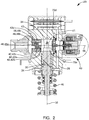
FIG. 2 is a cross-sectional view of the fuel pump ofFIG. 1 ; -
FIG. 3 is an exploded isometric view of an inlet valve assembly of the fuel pump ofFIGS. 1 and2 ; -
FIG. 4 is an enlargement of a portion ofFIG. 2 showing the inlet valve assembly of the fuel pump in a first position; -
FIG. 5 is the view ofFIG. 4 , now showing the inlet valve assembly in a second position; and -
FIG. 6 is the view ofFIGS. 4 and5 , now showing the inlet valve assembly in a transient position when moving from the position ofFIG. 5 to the position ofFIG. 4 . - In accordance with a preferred embodiment of this invention and referring initially to
FIG. 1 , afuel system 10 for aninternal combustion engine 12 is shown in schematic form.Fuel system 10 generally includes afuel tank 14 which holds a volume of fuel to be supplied tointernal combustion engine 12 for operation thereof; a plurality offuel injectors 16 which inject fuel directly into respective combustion chambers (not shown) ofinternal combustion engine 12; a low-pressure fuel pump 18; and a high-pressure fuel pump 20 where the low-pressure fuel pump 18 draws fuel fromfuel tank 14 and elevates the pressure of the fuel for delivery to high-pressure fuel pump 20 where the high-pressure fuel pump 20 further elevates the pressure of the fuel for delivery tofuel injectors 16. By way of non-limiting example only, low-pressure fuel pump 18 may elevate the pressure of the fuel to about 500 kPa or less and high-pressure fuel pump 20 may elevate the pressure of the fuel to above about 14 MPa and may be about 35MPa depending on the operational needs ofinternal combustion engine 12. While fourfuel injectors 16 have been illustrated, it should be understood that a lesser or greater number offuel injectors 16 may be provided. - As shown, low-
pressure fuel pump 18 may be provided withinfuel tank 14, however low-pressure fuel pump 18 may alternatively be provided outside offuel tank 14. Low-pressure fuel pump 18 may be an electric fuel pump as are well known to a practitioner of ordinary skill in the art. A low-pressurefuel supply passage 22 provides fluid communication from low-pressure fuel pump 18 to high-pressure fuel pump 20. Afuel pressure regulator 24 may be provided such thatfuel pressure regulator 24 maintains a substantially uniform pressure within low-pressurefuel supply passage 22 by returning a portion of the fuel supplied by low-pressure fuel pump 18 tofuel tank 14 through afuel return passage 26. Whilefuel pressure regulator 24 has been illustrated in low-pressurefuel supply passage 22 outside offuel tank 14, it should be understood thatfuel pressure regulator 24 may be located withinfuel tank 14 and may be integrated with low-pressure fuel pump 18. - Now with additional reference to
FIG. 2 , high-pressure fuel pump 20 includes afuel pump housing 28 which includes aplunger bore 30 which extends along, and is centered about, aplunger bore axis 32. As shown,plunger bore 30 may be defined by a combination of an insert and directly byfuel pump housing 28 but may alternatively be formed only, and directly by,fuel pump housing 28. High-pressure fuel pump 20 also includes apumping plunger 34 which is located withinplunger bore 30 and reciprocates within plunger bore 30 alongplunger bore axis 32 based on input from a rotatingcamshaft 36 of internal combustion engine 12 (shown only inFIG. 1 ). Apumping chamber 38 is defined withinfuel pump housing 28, and more specifically,pumping chamber 38 is defined byplunger bore 30 and pumpingplunger 34. Aninlet valve assembly 40 of high-pressure fuel pump 20 is located within a pumphousing inlet passage 41 offuel pump housing 28 and selectively allows fuel from low-pressure fuel pump 18 to enterpumping chamber 38 while an outlet valve assembly 42 is located within anoutlet valve bore 43 offuel pump housing 28 and selectively allows fuel to be communicated frompumping chamber 38 tofuel injectors 16 via afuel rail 44 to which eachfuel injector 16 is in fluid communication. In operation, reciprocation ofpumping plunger 34 causes the volume ofpumping chamber 38 to increase during an intake stroke of pumping plunger 34 (downward as oriented inFIG. 2 ) in which a plunger returnspring 46 causespumping plunger 34 to move downward, and conversely, the volume ofpumping chamber 38 decreases during a compression stroke (upward as oriented inFIG. 2 ) in whichcamshaft 36 causespumping plunger 34 to move upward against the force ofplunger return spring 46. In this way, fuel is drawn intopumping chamber 38 during the intake stroke, and conversely, fuel is pressurized withinpumping chamber 38 bypumping plunger 34 during the compression stroke, depending on the state of operation ofinlet valve assembly 40 as will be described in greater detail later, and discharged through outlet valve assembly 42 under pressure tofuel rail 44 andfuel injectors 16. For clarity,pumping plunger 34 is shown in solid lines inFIG. 2 to represent the intake stroke and pumpingplunger 34 is shown in phantom lines inFIG. 2 to represent the compression stroke. High-pressure fuel pump 20 also includes a pressure relief valve assembly 48 which is arranged downstream of outlet valve assembly 42 in order to provide a fluid path back topumping chamber 38 if the pressure downstream of outlet valve assembly 42 reaches a predetermined limit which may pose an unsafe operating condition if left unmitigated. - Outlet valve assembly 42 generally includes an outlet valve member 42a, an outlet valve seat 42b, and an outlet valve spring 42c where outlet valve seat 42b may be formed in an
outlet valve body 42d. The outer periphery of outlet valve seat 42b may be stepped as shown and fit withinoutlet valve bore 43 which is shaped in complementary fashion.Outlet valve body 42d may be fixed within outlet valve bore 43 by way of non-limiting example only, by interference fit, welding, complementary threads, threaded fasteners, combinations of two or more of the foregoing, and the like. Outlet valve member 42a, illustrated by way of non-limiting example only as a ball, is biased toward outlet valve seat 42b by outlet valve spring 42c where outlet valve spring 42c is selected to allow outlet valve member 42a to open when a predetermined pressure differential betweenpumping chamber 38 andfuel rail 44 is achieved. Outlet valve assembly 42 is oriented such that fuel is allowed to flow out ofpumping chamber 38 through outlet valve assembly 42, however, fuel is not allowed to flow intopumping chamber 38 through outlet valve assembly 42. - Pressure relief valve assembly 48 generally includes a pressure relief valve member 48a, a pressure relief valve seat 48b, and a pressure relief valve spring 48c where pressure relief valve seat 48b may be formed in an
outlet valve body 42d. Pressure relief valve member 48a, illustrated by way of non-limiting example only as a ball, is biased toward pressure relief valve seat 48b by pressure relief valve spring 48c where pressure relief valve spring 48c is selected to allow pressure relief valve member 48a to open when a predetermined pressure differential betweenpumping chamber 38 andfuel rail 44 is achieved. Pressure relief valve assembly 48 is oriented such that fuel is allowed to flow intopumping chamber 38 through pressure relief valve assembly 48, however, fuel is not allowed to flow out ofpumping chamber 38 through pressure relief valve assembly 48. While pressure relief valve assembly 48 has been illustrated herein as being commonly housed, and integrated with, outlet valve assembly 42, it should be understood that pressure relief valve assembly 48 may be formed entirely separate from outlet valve assembly 42. -
Inlet valve assembly 40 will now be described with continued reference toFIGS. 1 and2 and additionally with particular reference toFIGS. 3-6 .Inlet valve assembly 40 includes avalve seat 50, acheck valve 52, and asolenoid assembly 54. The various elements ofinlet valve assembly 40 will be described in greater detail in the paragraphs that follow. -
Valve seat 50 is centered about, and extends along, an inlet valve boreaxis 56 such thatvalve seat 50 extends from a valve seatfirst end 50a to a valve seatsecond end 50b where valve seatfirst end 50a is distal from pumpingchamber 38 and valve seatsecond end 50b is proximal to pumpingchamber 38. A valve seatcentral passage 66 extends throughvalve seat 50 such that valve seatcentral passage 66 connects valve seatfirst end 50a with valve seatsecond end 50b and such that valve seatcentral passage 66 is centered about, and extends along, inlet valve boreaxis 56. A plurality of valveseat flow passages 68 is provided invalve seat 50 such that each valveseat flow passage 68 extends throughvalve seat 50 and such that each valveseat flow passage 68 connects valve seatfirst end 50a with valve seatsecond end 50b. Each valveseat flow passage 68 is laterally offset from valve seatcentral passage 66 and extends throughvalve seat 50 in a direction parallel to inlet valve boreaxis 56. -
Valve seat 50 is located within an inlet valve bore 70 offuel pump housing 28 such that inlet valve bore 70 is located between pumphousing inlet passage 41 and pumpingchamber 38 and such that inlet valve bore 70 extends along, and is centered about inlet valve boreaxis 56. Inlet valve bore 70 is stepped such that inlet valve bore 70 includes ashoulder 70a which is traverse to inlet valve boreaxis 56.Shoulder 70a faces toward pumpingchamber 38. Inlet valve bore 70 includes an inlet valve bore first portion 70b which is proximal to pumpingchamber 38 and also includes an inlet valve bore second portion 70c which is distal from pumpingchamber 38. Inlet valve bore first portion 70b has afirst diameter 70d while inlet valve second portion has asecond diameter 70e which is less thanfirst diameter 70d, and in this way, the difference betweenfirst diameter 70d andsecond diameter 70e formsshoulder 70a such thatshoulder 70a joins inlet valve bore first portion 70b and inlet valve bore second portion 70c.Valve seat 50, and more particularly valve seatfirst end 50a, abutsshoulder 70a such thatvalve seat 50, due to the orientation ofshoulder 70a being toward pumpingchamber 38, is urged towardshoulder 70a when pressure is generated within pumpingchamber 38.Valve seat 50 is fixed within inlet valve bore first portion 70b by interference fit which also provides sealing to prevent fuel from passing between the interface between the outer periphery ofvalve seat 50 and the inner periphery of inlet valve bore first portion 70b. Consequently, whilevalve seat 50 may be fixed within inlet valve bore 70, by way of non-limiting example only, by an interference fit, the interference fit is not relied upon to resist the forces generated during the pumping stroke. Instead,shoulder 70a, which is formed by the geometry offuel pump housing 20, provides the support necessary to hold the axial position ofvalve seat 50 and resist the pressure generated within pumpingchamber 38, unlike the prior art which relies on one or more of interference fit, threaded connections, threaded fasteners, and welding to provide retention and resist the pressure generated within the pumping chamber. - Due to the stepped nature of inlet valve bore 70 with
shoulder 70a facing toward pumpingchamber 38,valve seat 50 must be installed from the direction of pumpingchamber 38. In order to allow installation ofvalve seat 50 from the direction of pumpingchamber 38, outlet valve bore 43 is sized to allow passage ofvalve seat 50 therethrough. In other words, the smallest portion of outlet valve bore 43 is greater than or equal to the largest portion ofvalve seat 50. As illustrated in the figures, outlet valve bore 43 may preferably be centered about inlet valve boreaxis 56 such that outlet valve bore 43 extends from pumpingchamber 38 in a diametrically opposed relationship to inlet valve bore 70. In this way, prior to assembly of outlet valve assembly 42 into outlet valve bore 43,valve seat 50 can be inserted through outlet valve bore 43 and pressed into inlet valve bore 70. - Check
valve 52 includes avalve member 78 and atravel limiter 80. Checkvalve 52 is arranged at valve seatsecond end 50b such thatvalve member 78 is moved between a seated position which blocks valve seat flow passages 68 (shown inFIG. 5 ) and an open position which unblocks valve seat flow passages 68 (shown inFIGS. 4 and6 ) as will be described in greater detail later.Valve member 78 includes a valve membercentral portion 78a which is a flat plate withvalve member passages 78b extending therethrough where it is noted that only selectvalve member passages 78b have been labeled inFIG. 3 for clarity.Valve member passages 78b are arranged through valve membercentral portion 78a such thatvalve member passages 78b are not axially aligned with valveseat flow passages 68. A plurality ofvalve member legs 78c extend from valve membercentral portion 78a such thatvalve member legs 78c are resilient and compliant. Free ends ofvalve member legs 78c are fixed to valve seatsecond end 50b, for example, by welding. Consequently, when the pressure differential between pumphousing inlet passage 41 and pumpingchamber 38 is sufficiently high, valve membercentral portion 78a is allowed to unseat from valve seatsecond end 50b due to elastic deformation ofvalve member legs 78c, thereby opening valveseat flow passages 68.Travel limiter 80 includes atravel limiter ring 80a which is axially spaced apart from valve seatsecond end 50b to provide the allowable amount of displacement ofvalve member 78.Travel limiter 80 also includes a plurality oftravel limiter legs 80b which provide the axial spacing betweentravel limiter ring 80a and valve seatsecond end 50b.Travel limiter legs 80b are integrally formed withtravel limiter ring 80a and are fixed to valve seatsecond end 50b, for example by welding. -
Solenoid assembly 54 includes aninner housing 82, apole piece 84 located withininner housing 82, an armature 85 located withininner housing 82, areturn spring 86 which biases armature 83 away frompole piece 84, acontrol rod 87, aspool 88, acoil 90, anovermold 92, and anouter housing 94. The various elements ofsolenoid assembly 54 will be described in greater detail in the paragraphs that follow. -
Inner housing 82 is hollow and is centered about, and extends along, inlet valve boreaxis 56. The outer periphery ofinner housing 82 engages the inner periphery of a solenoid bore 95 offuel pump housing 28 where solenoid bore 95 is centered about, and extends along inlet valve boreaxis 56.Inner housing 82 is welded tofuel pump housing 28, thereby fixingsolenoid assembly 54 tofuel pump housing 28. -
Pole piece 84 is made of a magnetically permeable material and is received withininner housing 82 in fixed relationship toinner housing 82, for example by interference fit or welding, such thatpole piece 84 is centered about, and extends along, inlet valve boreaxis 56. A pole piecefirst end 84a ofpole piece 84 includes a polepiece spring pocket 84b extending thereinto from pole piecefirst end 84a to a pole piece springpocket bottom surface 84c such that polepiece spring pocket 84b may be cylindrical and centered about inlet valve boreaxis 56 and such that a portion ofreturn spring 86 is located within polepiece spring pocket 84b in abutment with pole piece springpocket bottom surface 84c. - Armature 85 is made of a material which is attracted by a magnet and is received within
inner housing 82 in a slidable relationship toinner housing 82 along inlet valve boreaxis 56 such that armature 85 is centered about, and extends along, inlet valve boreaxis 56. Armature 85 may be of two-piece construction as shown which includes an armature first portion 85a which is proximal topole piece 84 and an armature second portion 85b which is fixed to armature first portion 85a, for example, by welding or mechanical fasteners and which is distal frompole piece 84. Armature first portion 85a includes anarmature spring bore 85c extending thereinto from an armature first end 85d which is proximal topole piece 84 and which is centered about, and extends along, inlet valve boreaxis 56. A portion ofreturn spring 86 is located withinarmature spring bore 85c and abuts against armature second portion 85b such thatreturn spring 86 is held in compression between armature second portion 85b and pole piece springpocket bottom surface 84c, thereby biasing armature 85 in a direction away frompole piece 84. Armature second portion 85b includes an armature control rod bore 85e extending axially therethrough such that armaturecontrol rod bore 85e is centered about, and extends along, inlet valve boreaxis 56. -
Control rod 87 extends from a control rodfirst end 87a which is proximal to armature 85 to a control rodsecond end 87b which is proximal tovalve member 78 such thatcontrol rod 87 is centered about, and extends along, inlet valve boreaxis 56.Control rod 87 includes a control rodfirst shoulder 87c which is annular in shape and faces toward armature 85, and as shown, is transverse to inlet valve boreaxis 56. A control rodfirst surface 87d extends from control rodfirst end 87a to control rodfirst shoulder 87c such that control rodfirst surface 87d is located at least partially within armature control rod bore 85e in a close sliding interface which allows control rodfirst surface 87d to freely move axially, i.e. along inlet valve boreaxis 56, within armature control rod bore 85e while preventing radial movement, i.e. transverse to inlet valve boreaxis 56, of control rodfirst surface 87d within armaturecontrol rod bore 85e. It is important to note that the close sliding interface between control rodfirst surface 87d and armaturecontrol rod bore 85e allowscontrol rod 87 to move along inlet valve boreaxis 56 independently of armature 85. Control rodfirst shoulder 87c limits the extent to which control rodfirst surface 87d is inserted into armature control rod bore 85e and control rodfirst shoulder 87c also provides a surface for armature 85 to react against in order to movecontrol rod 87 towardvalve member 78 as will be described in greater detail later.Control rod 87 includes a control rodsecond shoulder 87e which is annular in shape and faces towardvalve seat 50, and as shown, is transverse to inlet valve boreaxis 56. A control rodsecond surface 87f extends from control rodsecond end 87b to control rodsecond shoulder 87e such that control rodsecond surface 87f is located at least partially within valve seatcentral passage 66 in a close sliding interface which allows control rodsecond surface 87f to freely move axially, i.e. along inlet valve boreaxis 56, within valve seatcentral passage 66 while preventing radial movement, i.e. transverse to inlet valve boreaxis 56, of control rodsecond surface 87f within valve seatcentral passage 66. In use, control rodsecond end 87b is used to interface withcheck valve 52, and more particularlyvalve member 78, as will be described in greater detail later. - As illustrated herein,
control rod 87 may be of multi-piece construction which includes a control rodcentral portion 87g, a control rodfirst bushing 87h which is tubular and fixed to control rodcentral portion 87g, and a control rodsecond bushing 87i which is tubular and fixed to control rodcentral portion 87g. Control rodcentral portion 87g is preferably cylindrical and is centered about inlet valve boreaxis 56 such that control rodcentral portion 87g extends from control rodfirst end 87a to control rodsecond end 87b. By way of non-limiting example only, control rodcentral portion 87g may be a roller bearing which is commercially available. Control rodfirst bushing 87h is preferably cylindrical on its outer periphery which is centered about, and extends along inlet valve boreaxis 56 such that control rodfirst shoulder 87c is defined by one axial end of control rodfirst bushing 87h. Control rodfirst bushing 87h includes a control rod first bushing bore 87j extending axially therethrough such that control rod first bushing bore 87j is preferably cylindrical. In order to prevent relative movement between control rodfirst bushing 87h and control rodcentral portion 87g, control rodfirst bushing 87h is fixed to control rodcentral portion 87g, for example, by one or more of interference fit between control rod first bushing bore 87j and control rodcentral portion 87g and welding. Similarly, control rodsecond bushing 87i is preferably cylindrical on its outer periphery which is centered about, and extends along, inlet valve boreaxis 56 such that control rodsecond shoulder 87e is defined by one axial end of control rodsecond bushing 87i. Control rodsecond bushing 87i includes a control rod second bushing bore 87k extending axially therethrough such that control rodsecond bushing bore 87k is preferably cylindrical. In order to prevent relative movement between control rodsecond bushing 87i and control rodcentral portion 87g, control rodsecond bushing 87i is fixed to control rodcentral portion 87g, for example, by one or more of interference fit between control rod second bushing bore 87k and control rodcentral portion 87g and welding. By makingcontrol rod 87 a multi-piece component, control rodcentral portion 87g may be provided as a roller bearing which is commercially available in high volumes at low cost with surface finishes and tolerances which are important to the close sliding fit needed betweencontrol rod 87 and valve seatcentral passage 66 and betweencontrol rod 87 and armaturecontrol rod bore 85e. In an alternative arrangement, control rodfirst bushing 87h and control rodsecond bushing 87i may be combined to be a single bushing which minimizes the number of components, but has the drawback of increasing mass. In a further alternative,control rod 87 may be formed as a single piece of material in a turning operation. - While
control rod 87 has been illustrated herein as being decoupled from armature 85, i.e.control rod 87 is able to move independently of armature 85, it should be understood thatcontrol rod 87 may be rigidly fixed to armature 85 such thatcontrol rod 87 always moves together with armature 85. -
Spool 88 is made of an electrically insulative material, for example plastic, and is centered about, and extends along, inlet valve boreaxis 56 such thatspool 88 circumferentially surroundsinner housing 82 in a close-fitting relationship.Coil 90 is a winding of electrically conductive wire which is wound about the outer periphery ofspool 88 such thatcoil 90 circumferentially surrounds a portion ofpole piece 84. Consequently, whencoil 90 is energized with an electric current, armature 85 is magnetically attracted to, and moved toward,pole piece 84, and whencoil 90 is not energized with an electric current, armature 85 is moved away frompole piece 84 byreturn spring 86. A more detailed description of operation will be provided later. -
Outer housing 94 circumferentially surroundsinner housing 82,spool 88, andcoil 90 such thatspool 88 andcoil 90 are located radially betweeninner housing 82 andouter housing 94.Overmold 92 is an electrically insulative material, for example plastic, which fills the void betweenspool 88/coil 90 andouter housing 94 such thatovermold 92 extends axially fromouter housing 94 to define anelectrical connector 96 which includes terminals (not shown) that are connected to opposite ends ofcoil 90.Electrical connector 96 is configured to mate with a complementary electrical connector (not show) for supplying electric current tocoil 90 in use. As shown, acoil washer 98 may be provided withinouter housing 94 axially betweencoil 90 andovermold 92 in order to complete the magnetic circuit ofsolenoid assembly 54. - Operation of high-
pressure fuel pump 20, and in particular,inlet valve assembly 40, will now be described with particular reference toFIG. 4 which shows armature 85 in a first position which results from no electric current being supplied tocoil 90 ofsolenoid assembly 54. When no electric current is supplied tocoil 90,return spring 86 urges armature 85 away frompole piece 84. As armature 85 is urged away frompole piece 84, armature second portion 85b comes into contact with control rodfirst shoulder 87c andcontrol rod 87 is urged towardvalve member 78 until control rodsecond shoulder 87e abuts valve seat first end 54a which allows control rodsecond end 87b to protrude beyond valve seatsecond end 50b such that control rodsecond end 87b movesvalve member 78 to, and holdsvalve member 78 in, an unseated position which permits flow through valveseat flow passages 68 and such that valveseat flow passages 68 are in fluid communication with pumpingchamber 38. However, it is important to note that armature 85 may not remain in contact with control rodfirst shoulder 87c for the entire duration of travel, thereby allowing control rodsecond shoulder 87e to abut valve seatfirst end 50a before armature 85 again comes into contact with control rodfirst shoulder 87c. Consequently, two smaller, individual impacts may result which helps to minimize noise. To illustrate this phenomenon,FIG. 6 shows a transient position where control rodsecond shoulder 87e has impacted valve seatfirst end 50a, however, armature 85 has not yet regained contact with control rodfirst shoulder 87c. Without being bound by theory, this may result from armature 85 impacting control rodfirst shoulder 87c and propellingcontrol rod 87 ahead of armature 85. Holdingopen valve member 78 open may be utilized to allow fuel to spill back toward pumphousing inlet passage 41 during a portion of the compression stroke of pumpingplunger 34 based on the mass of fuel that is needed to be delivered tofuel injectors 16, i.e. different operating conditions ofinternal combustion engine 12 require different fuel masses to be delivered tofuel injectors 16 for each pumping cycle of pumpingplunger 34 and the mass of fuel delivered tofuel injectors 16 can be adjusted by allowing a portion of the fuel involved in a compression stroke to be spilled back to pumphousing inlet passage 41. Anelectronic control unit 100 may be used to time the supply of electric current tocoil 90 during the compression stroke, thereby varying the proportion of fuel from the compression stroke that is supplied tofuel injectors 16 and the proportion of fuel from the compression stroke that is spilled back to pumphousing inlet passage 41.Electronic control unit 100 may receive input from apressure sensor 102 which senses the pressure withinfuel rail 44 in order to provide proper timing of the supply electric current tocoil 90 in order to maintain a desired pressure infuel rail 44 which may vary based on the commanded torque desired to be produced byinternal combustion engine 12. - Now with particular reference to
FIG. 5 , armature 85 is shown in a second position which results from electric current being supplied tocoil 90 ofsolenoid assembly 54. When electric current is supplied tocoil 90, armature 85 is attracted to, and moves toward,pole piece 84 until armature first end 85d abuts pole piecefirst end 84a. When electric current is supplied tocoil 90 during the compression stroke of pumpingplunger 34, fuel pressure within pumpingchamber 38 acts onvalve member 78, and since armature 85 is no longer acting uponcontrol rod 87,valve member 78 urgescontrol rod 87 toward armature 85 untilvalve member 78 blocks valveseat flow passages 68. It should be noted that sincecontrol rod 87 and armature 85 are allowed to move independently of each other along inlet valve boreaxis 56, armature 85 separates from control rodfirst shoulder 87c. As a result, an impact resulting only from the mass of armature 85 coming into abutment withpole piece 84 occurs. Furthermore, since this impact does not include the mass ofcontrol rod 87, a smaller sound intensity is produced compared to prior art inlet control valves. It should also be noted that the position of armature 85 illustrated inFIG. 5 does not requirevalve member 78 to be in the seated position, but rather, the state ofvalve member 78 is determined by the differential pressure acrossvalve member 78. In this way,valve member 78 is opened during the intake stroke to allow fuel to flow into pumpingchamber 38. - In an alternative which is not shown,
inlet valve assembly 40 may alternatively be arranged to be coaxial with plunger bore 30, thereby placing the shoulder which supportsvalve seat 50 above (as oriented in the figures) pumpingplunger 34. Such an arrangement would allow insertion ofvalve seat 50 through the bore offuel pump housing 28 which receives the insert within which pumpingplunger 34 reciprocates where it is noted thatvalve seat 50 would positioned prior to the insert being placed within the housing. - High-
pressure fuel pump 20 withvalve seat 50 supported byshoulder 70a offuel pump housing 28 as described herein allows the high cyclic load generated by the pressurization of fuel within pumpingchamber 38 to be carried directly byfuel pump housing 28 rather than by secondary means such as interference fit, threaded connections, welding, and threaded fasteners as is currently used in the prior art. In this way, the number of components and processes is reduced, thereby reducing cost and providing a more robust connection. - While this invention has been described in terms of preferred embodiments thereof, it is not intended to be so limited, but rather only to the extent set forth in the claims that follow.
Claims (11)
- A fuel pump (20) comprising:a fuel pump housing (28) with a pumping chamber (38) defined therein, said fuel pump housing (28) having an inlet valve bore (70) which is connectable to a source of fuel via a pump housing inlet passage (41), said inlet valve bore (70) extending along an inlet valve bore axis (56) and being stepped such that said inlet valve bore (70) includes a shoulder (70a) which is traverse to said inlet valve bore axis (56);a pumping plunger (34) which reciprocates within a plunger bore (30) along a plunger bore axis (32) such that an intake stroke of said pumping plunger (34) increases volume of said pumping chamber (38) and a compression stroke of said pumping plunger (34) decreases volume of said pumping chamber (38); andan inlet valve assembly (40) comprising:a valve seat (50) with a valve seat flow passage (68) extending therethrough, said valve seat (50) being located within said inlet valve bore (70) such that said valve seat (50) abuts said shoulder (70a) and is urged toward said shoulder (70a) by pressure within said pumping chamber (38) during said compression stroke;a valve member (78) which is moveable between 1) an unseated position which provides fluid communication through said valve seat flow passage (68) and 2) a seated position which prevents fluid communication through said valve seat flow passage (68).
- A fuel pump (20) as in claim 1, wherein said shoulder (70a) faces toward said pumping chamber (38).
- A fuel pump (20) as in claim 1, wherein:said inlet valve bore (70) includes an inlet valve bore first portion (70b) which is proximal to said pumping chamber (38) and which has a first diameter (70d);said inlet valve bore (70) includes an inlet valve bore second portion (70c) which is distal from said pumping chamber (38) and which has a second diameter (70e) that is less than said first diameter (70d).
- A fuel pump (20) as in claim 3, wherein said shoulder (70a) joins said inlet valve bore first portion (70b) and said inlet valve bore second portion (70c).
- A fuel pump (20) as in claim 3, wherein said fuel pump housing (28) includes a second bore (43) extending therethrough from said pumping chamber (38) such that said second bore (43) is sized to allow passage of said valve seat (50) therethrough to accommodate installation of said valve seat (50) into said inlet valve bore first portion (70b) through said second bore (43).
- A fuel pump (20) as in claim 5, wherein said second bore (43) is diametrically opposed to said inlet valve bore (70).
- A fuel pump (20) as in claim 5, wherein:said inlet valve bore (70) is centered about said inlet valve bore axis (56); andsaid second bore (43) is centered about said inlet valve bore axis (56).
- A fuel pump (20) as in claim 5, wherein said fuel pump (20) further comprises an outlet valve assembly (42) which is located within said second bore (43), said outlet valve assembly (42) allowing pressurized fuel to flow out of said pumping chamber (38) and preventing fuel from flowing back into said pumping chamber (38).
- A fuel pump (20) as in claim 8, wherein:said inlet valve bore (70) is centered about said inlet valve bore axis (56); andsaid second bore (43) is centered about said inlet valve bore axis (56).
- A fuel pump (20) as in claim 3, wherein said valve seat (50) is fixed within said inlet valve bore first portion (70b) by interference fit such that an outer periphery of said valve seat (50) is sealed to an inner periphery of said inlet valve bore first portion (70a).
- A fuel pump (20) as in claim 3, wherein said shoulder (70a) faces toward said pumping chamber (38).
Applications Claiming Priority (1)
| Application Number | Priority Date | Filing Date | Title |
|---|---|---|---|
| US16/270,883 US11499515B2 (en) | 2019-02-08 | 2019-02-08 | Fuel pump and inlet valve assembly thereof |
Publications (2)
| Publication Number | Publication Date |
|---|---|
| EP3693599A1 true EP3693599A1 (en) | 2020-08-12 |
| EP3693599B1 EP3693599B1 (en) | 2021-11-03 |
Family
ID=69500563
Family Applications (1)
| Application Number | Title | Priority Date | Filing Date |
|---|---|---|---|
| EP20155561.2A Active EP3693599B1 (en) | 2019-02-08 | 2020-02-05 | Fuel pump and inlet valve assembly thereof |
Country Status (2)
| Country | Link |
|---|---|
| US (1) | US11499515B2 (en) |
| EP (1) | EP3693599B1 (en) |
Cited By (1)
| Publication number | Priority date | Publication date | Assignee | Title |
|---|---|---|---|---|
| FR3158984A1 (en) * | 2024-02-06 | 2025-08-08 | Phinia Delphi Luxembourg Sarl | Fuel pump and its assembly method |
Families Citing this family (3)
| Publication number | Priority date | Publication date | Assignee | Title |
|---|---|---|---|---|
| GB2553484A (en) * | 2016-04-26 | 2018-03-14 | Delphi Int Operations Luxembourg Sarl | High pressure diesel pump |
| CN116292004A (en) * | 2021-12-21 | 2023-06-23 | 马瑞利欧洲公司 | Fuel pump for direct injection system |
| GB2620930B (en) * | 2022-07-25 | 2024-12-25 | Phinia Delphi Luxembourg Sarl | Pump |
Citations (4)
| Publication number | Priority date | Publication date | Assignee | Title |
|---|---|---|---|---|
| US20060239846A1 (en) * | 2005-04-26 | 2006-10-26 | Denso Corporation | High pressure pump having solenoid actuator |
| US7401594B2 (en) | 2003-07-22 | 2008-07-22 | Hitachi, Ltd. | Damper mechanism and high pressure fuel pump |
| US7707996B2 (en) | 1999-02-09 | 2010-05-04 | Hitachi, Ltd. | High pressure fuel supply pump for internal combustion engine |
| US20170248110A1 (en) * | 2014-08-28 | 2017-08-31 | Hitachi Automotive Systems, Ltd. | High pressure fuel supply pump |
Family Cites Families (3)
| Publication number | Priority date | Publication date | Assignee | Title |
|---|---|---|---|---|
| JP5002523B2 (en) * | 2008-04-25 | 2012-08-15 | 日立オートモティブシステムズ株式会社 | Fuel pressure pulsation reduction mechanism and high-pressure fuel supply pump for internal combustion engine equipped with the same |
| JP5501272B2 (en) * | 2011-03-08 | 2014-05-21 | 日立オートモティブシステムズ株式会社 | High pressure fuel supply pump |
| US20140190441A1 (en) * | 2013-01-04 | 2014-07-10 | Ford Global Technologies, Llc | Valve seat insert |
-
2019
- 2019-02-08 US US16/270,883 patent/US11499515B2/en active Active
-
2020
- 2020-02-05 EP EP20155561.2A patent/EP3693599B1/en active Active
Patent Citations (4)
| Publication number | Priority date | Publication date | Assignee | Title |
|---|---|---|---|---|
| US7707996B2 (en) | 1999-02-09 | 2010-05-04 | Hitachi, Ltd. | High pressure fuel supply pump for internal combustion engine |
| US7401594B2 (en) | 2003-07-22 | 2008-07-22 | Hitachi, Ltd. | Damper mechanism and high pressure fuel pump |
| US20060239846A1 (en) * | 2005-04-26 | 2006-10-26 | Denso Corporation | High pressure pump having solenoid actuator |
| US20170248110A1 (en) * | 2014-08-28 | 2017-08-31 | Hitachi Automotive Systems, Ltd. | High pressure fuel supply pump |
Cited By (1)
| Publication number | Priority date | Publication date | Assignee | Title |
|---|---|---|---|---|
| FR3158984A1 (en) * | 2024-02-06 | 2025-08-08 | Phinia Delphi Luxembourg Sarl | Fuel pump and its assembly method |
Also Published As
| Publication number | Publication date |
|---|---|
| US20200256300A1 (en) | 2020-08-13 |
| EP3693599B1 (en) | 2021-11-03 |
| US11499515B2 (en) | 2022-11-15 |
Similar Documents
| Publication | Publication Date | Title |
|---|---|---|
| EP3839240B1 (en) | Fuel pump and outlet valve seat thereof | |
| EP3663571B1 (en) | Fuel pump and inlet valve assembly thereof | |
| EP3693599B1 (en) | Fuel pump and inlet valve assembly thereof | |
| EP3696400B1 (en) | Combination outlet valve and pressure relief valve and fuel pump using the same | |
| EP3715619B1 (en) | Fuel pump for gasoline direct injection | |
| JP4413260B2 (en) | High pressure fuel pump | |
| EP3628857B1 (en) | Fuel pump and outlet valve thereof | |
| EP3591214B1 (en) | Fuel pump and inlet valve assembly thereof | |
| EP4341548B1 (en) | Fuel pump with inlet valve assembly | |
| CN114787497A (en) | Discharge valve mechanism and high-pressure fuel supply pump provided with same | |
| JP5789954B2 (en) | solenoid valve | |
| JP2020084896A (en) | High-pressure fuel pump | |
| JP2019100310A (en) | High-pressure fuel pump |
Legal Events
| Date | Code | Title | Description |
|---|---|---|---|
| PUAI | Public reference made under article 153(3) epc to a published international application that has entered the european phase |
Free format text: ORIGINAL CODE: 0009012 |
|
| STAA | Information on the status of an ep patent application or granted ep patent |
Free format text: STATUS: THE APPLICATION HAS BEEN PUBLISHED |
|
| AK | Designated contracting states |
Kind code of ref document: A1 Designated state(s): AL AT BE BG CH CY CZ DE DK EE ES FI FR GB GR HR HU IE IS IT LI LT LU LV MC MK MT NL NO PL PT RO RS SE SI SK SM TR |
|
| AX | Request for extension of the european patent |
Extension state: BA ME |
|
| STAA | Information on the status of an ep patent application or granted ep patent |
Free format text: STATUS: REQUEST FOR EXAMINATION WAS MADE |
|
| 17P | Request for examination filed |
Effective date: 20210212 |
|
| RBV | Designated contracting states (corrected) |
Designated state(s): AL AT BE BG CH CY CZ DE DK EE ES FI FR GB GR HR HU IE IS IT LI LT LU LV MC MK MT NL NO PL PT RO RS SE SI SK SM TR |
|
| GRAP | Despatch of communication of intention to grant a patent |
Free format text: ORIGINAL CODE: EPIDOSNIGR1 |
|
| STAA | Information on the status of an ep patent application or granted ep patent |
Free format text: STATUS: GRANT OF PATENT IS INTENDED |
|
| INTG | Intention to grant announced |
Effective date: 20210615 |
|
| GRAS | Grant fee paid |
Free format text: ORIGINAL CODE: EPIDOSNIGR3 |
|
| GRAA | (expected) grant |
Free format text: ORIGINAL CODE: 0009210 |
|
| STAA | Information on the status of an ep patent application or granted ep patent |
Free format text: STATUS: THE PATENT HAS BEEN GRANTED |
|
| AK | Designated contracting states |
Kind code of ref document: B1 Designated state(s): AL AT BE BG CH CY CZ DE DK EE ES FI FR GB GR HR HU IE IS IT LI LT LU LV MC MK MT NL NO PL PT RO RS SE SI SK SM TR |
|
| REG | Reference to a national code |
Ref country code: GB Ref legal event code: FG4D |
|
| REG | Reference to a national code |
Ref country code: AT Ref legal event code: REF Ref document number: 1444160 Country of ref document: AT Kind code of ref document: T Effective date: 20211115 Ref country code: CH Ref legal event code: EP |
|
| REG | Reference to a national code |
Ref country code: DE Ref legal event code: R096 Ref document number: 602020000872 Country of ref document: DE |
|
| REG | Reference to a national code |
Ref country code: IE Ref legal event code: FG4D |
|
| REG | Reference to a national code |
Ref country code: LT Ref legal event code: MG9D |
|
| REG | Reference to a national code |
Ref country code: NL Ref legal event code: MP Effective date: 20211103 |
|
| REG | Reference to a national code |
Ref country code: AT Ref legal event code: MK05 Ref document number: 1444160 Country of ref document: AT Kind code of ref document: T Effective date: 20211103 |
|
| RAP4 | Party data changed (patent owner data changed or rights of a patent transferred) |
Owner name: DELPHI TECHNOLOGIES IP LIMITED |
|
| PG25 | Lapsed in a contracting state [announced via postgrant information from national office to epo] |
Ref country code: RS Free format text: LAPSE BECAUSE OF FAILURE TO SUBMIT A TRANSLATION OF THE DESCRIPTION OR TO PAY THE FEE WITHIN THE PRESCRIBED TIME-LIMIT Effective date: 20211103 Ref country code: LT Free format text: LAPSE BECAUSE OF FAILURE TO SUBMIT A TRANSLATION OF THE DESCRIPTION OR TO PAY THE FEE WITHIN THE PRESCRIBED TIME-LIMIT Effective date: 20211103 Ref country code: FI Free format text: LAPSE BECAUSE OF FAILURE TO SUBMIT A TRANSLATION OF THE DESCRIPTION OR TO PAY THE FEE WITHIN THE PRESCRIBED TIME-LIMIT Effective date: 20211103 Ref country code: BG Free format text: LAPSE BECAUSE OF FAILURE TO SUBMIT A TRANSLATION OF THE DESCRIPTION OR TO PAY THE FEE WITHIN THE PRESCRIBED TIME-LIMIT Effective date: 20220203 Ref country code: AT Free format text: LAPSE BECAUSE OF FAILURE TO SUBMIT A TRANSLATION OF THE DESCRIPTION OR TO PAY THE FEE WITHIN THE PRESCRIBED TIME-LIMIT Effective date: 20211103 |
|
| REG | Reference to a national code |
Ref country code: DE Ref legal event code: R081 Ref document number: 602020000872 Country of ref document: DE Owner name: DELPHI TECHNOLOGIES IP LIMITED, BB Free format text: FORMER OWNER: DELPHI TECHNOLOGIES IP LIMITED, SAINT MICHAEL, BB Ref country code: DE Ref legal event code: R081 Ref document number: 602020000872 Country of ref document: DE Owner name: PHINIA DELPHI LUXEMBOURG SARL, LU Free format text: FORMER OWNER: DELPHI TECHNOLOGIES IP LIMITED, SAINT MICHAEL, BB |
|
| PG25 | Lapsed in a contracting state [announced via postgrant information from national office to epo] |
Ref country code: IS Free format text: LAPSE BECAUSE OF FAILURE TO SUBMIT A TRANSLATION OF THE DESCRIPTION OR TO PAY THE FEE WITHIN THE PRESCRIBED TIME-LIMIT Effective date: 20220303 Ref country code: SE Free format text: LAPSE BECAUSE OF FAILURE TO SUBMIT A TRANSLATION OF THE DESCRIPTION OR TO PAY THE FEE WITHIN THE PRESCRIBED TIME-LIMIT Effective date: 20211103 Ref country code: PT Free format text: LAPSE BECAUSE OF FAILURE TO SUBMIT A TRANSLATION OF THE DESCRIPTION OR TO PAY THE FEE WITHIN THE PRESCRIBED TIME-LIMIT Effective date: 20220303 Ref country code: PL Free format text: LAPSE BECAUSE OF FAILURE TO SUBMIT A TRANSLATION OF THE DESCRIPTION OR TO PAY THE FEE WITHIN THE PRESCRIBED TIME-LIMIT Effective date: 20211103 Ref country code: NO Free format text: LAPSE BECAUSE OF FAILURE TO SUBMIT A TRANSLATION OF THE DESCRIPTION OR TO PAY THE FEE WITHIN THE PRESCRIBED TIME-LIMIT Effective date: 20220203 Ref country code: NL Free format text: LAPSE BECAUSE OF FAILURE TO SUBMIT A TRANSLATION OF THE DESCRIPTION OR TO PAY THE FEE WITHIN THE PRESCRIBED TIME-LIMIT Effective date: 20211103 Ref country code: LV Free format text: LAPSE BECAUSE OF FAILURE TO SUBMIT A TRANSLATION OF THE DESCRIPTION OR TO PAY THE FEE WITHIN THE PRESCRIBED TIME-LIMIT Effective date: 20211103 Ref country code: HR Free format text: LAPSE BECAUSE OF FAILURE TO SUBMIT A TRANSLATION OF THE DESCRIPTION OR TO PAY THE FEE WITHIN THE PRESCRIBED TIME-LIMIT Effective date: 20211103 Ref country code: GR Free format text: LAPSE BECAUSE OF FAILURE TO SUBMIT A TRANSLATION OF THE DESCRIPTION OR TO PAY THE FEE WITHIN THE PRESCRIBED TIME-LIMIT Effective date: 20220204 Ref country code: ES Free format text: LAPSE BECAUSE OF FAILURE TO SUBMIT A TRANSLATION OF THE DESCRIPTION OR TO PAY THE FEE WITHIN THE PRESCRIBED TIME-LIMIT Effective date: 20211103 |
|
| PG25 | Lapsed in a contracting state [announced via postgrant information from national office to epo] |
Ref country code: SM Free format text: LAPSE BECAUSE OF FAILURE TO SUBMIT A TRANSLATION OF THE DESCRIPTION OR TO PAY THE FEE WITHIN THE PRESCRIBED TIME-LIMIT Effective date: 20211103 Ref country code: SK Free format text: LAPSE BECAUSE OF FAILURE TO SUBMIT A TRANSLATION OF THE DESCRIPTION OR TO PAY THE FEE WITHIN THE PRESCRIBED TIME-LIMIT Effective date: 20211103 Ref country code: RO Free format text: LAPSE BECAUSE OF FAILURE TO SUBMIT A TRANSLATION OF THE DESCRIPTION OR TO PAY THE FEE WITHIN THE PRESCRIBED TIME-LIMIT Effective date: 20211103 Ref country code: EE Free format text: LAPSE BECAUSE OF FAILURE TO SUBMIT A TRANSLATION OF THE DESCRIPTION OR TO PAY THE FEE WITHIN THE PRESCRIBED TIME-LIMIT Effective date: 20211103 Ref country code: DK Free format text: LAPSE BECAUSE OF FAILURE TO SUBMIT A TRANSLATION OF THE DESCRIPTION OR TO PAY THE FEE WITHIN THE PRESCRIBED TIME-LIMIT Effective date: 20211103 Ref country code: CZ Free format text: LAPSE BECAUSE OF FAILURE TO SUBMIT A TRANSLATION OF THE DESCRIPTION OR TO PAY THE FEE WITHIN THE PRESCRIBED TIME-LIMIT Effective date: 20211103 |
|
| REG | Reference to a national code |
Ref country code: DE Ref legal event code: R097 Ref document number: 602020000872 Country of ref document: DE |
|
| PLBE | No opposition filed within time limit |
Free format text: ORIGINAL CODE: 0009261 |
|
| STAA | Information on the status of an ep patent application or granted ep patent |
Free format text: STATUS: NO OPPOSITION FILED WITHIN TIME LIMIT |
|
| PG25 | Lapsed in a contracting state [announced via postgrant information from national office to epo] |
Ref country code: MC Free format text: LAPSE BECAUSE OF FAILURE TO SUBMIT A TRANSLATION OF THE DESCRIPTION OR TO PAY THE FEE WITHIN THE PRESCRIBED TIME-LIMIT Effective date: 20211103 |
|
| 26N | No opposition filed |
Effective date: 20220804 |
|
| REG | Reference to a national code |
Ref country code: BE Ref legal event code: MM Effective date: 20220228 |
|
| PG25 | Lapsed in a contracting state [announced via postgrant information from national office to epo] |
Ref country code: LU Free format text: LAPSE BECAUSE OF NON-PAYMENT OF DUE FEES Effective date: 20220205 Ref country code: AL Free format text: LAPSE BECAUSE OF FAILURE TO SUBMIT A TRANSLATION OF THE DESCRIPTION OR TO PAY THE FEE WITHIN THE PRESCRIBED TIME-LIMIT Effective date: 20211103 |
|
| PG25 | Lapsed in a contracting state [announced via postgrant information from national office to epo] |
Ref country code: SI Free format text: LAPSE BECAUSE OF FAILURE TO SUBMIT A TRANSLATION OF THE DESCRIPTION OR TO PAY THE FEE WITHIN THE PRESCRIBED TIME-LIMIT Effective date: 20211103 |
|
| PG25 | Lapsed in a contracting state [announced via postgrant information from national office to epo] |
Ref country code: IE Free format text: LAPSE BECAUSE OF NON-PAYMENT OF DUE FEES Effective date: 20220205 |
|
| PG25 | Lapsed in a contracting state [announced via postgrant information from national office to epo] |
Ref country code: BE Free format text: LAPSE BECAUSE OF NON-PAYMENT OF DUE FEES Effective date: 20220228 |
|
| PG25 | Lapsed in a contracting state [announced via postgrant information from national office to epo] |
Ref country code: IT Free format text: LAPSE BECAUSE OF FAILURE TO SUBMIT A TRANSLATION OF THE DESCRIPTION OR TO PAY THE FEE WITHIN THE PRESCRIBED TIME-LIMIT Effective date: 20211103 |
|
| P01 | Opt-out of the competence of the unified patent court (upc) registered |
Effective date: 20230327 |
|
| REG | Reference to a national code |
Ref country code: CH Ref legal event code: PL |
|
| PG25 | Lapsed in a contracting state [announced via postgrant information from national office to epo] |
Ref country code: LI Free format text: LAPSE BECAUSE OF NON-PAYMENT OF DUE FEES Effective date: 20230228 Ref country code: CH Free format text: LAPSE BECAUSE OF NON-PAYMENT OF DUE FEES Effective date: 20230228 |
|
| REG | Reference to a national code |
Ref country code: DE Ref legal event code: R081 Ref document number: 602020000872 Country of ref document: DE Owner name: PHINIA DELPHI LUXEMBOURG SARL, LU Free format text: FORMER OWNER: DELPHI TECHNOLOGIES IP LIMITED, ST. MICHAEL, BB |
|
| PG25 | Lapsed in a contracting state [announced via postgrant information from national office to epo] |
Ref country code: MK Free format text: LAPSE BECAUSE OF FAILURE TO SUBMIT A TRANSLATION OF THE DESCRIPTION OR TO PAY THE FEE WITHIN THE PRESCRIBED TIME-LIMIT Effective date: 20211103 Ref country code: CY Free format text: LAPSE BECAUSE OF FAILURE TO SUBMIT A TRANSLATION OF THE DESCRIPTION OR TO PAY THE FEE WITHIN THE PRESCRIBED TIME-LIMIT Effective date: 20211103 |
|
| PG25 | Lapsed in a contracting state [announced via postgrant information from national office to epo] |
Ref country code: HU Free format text: LAPSE BECAUSE OF FAILURE TO SUBMIT A TRANSLATION OF THE DESCRIPTION OR TO PAY THE FEE WITHIN THE PRESCRIBED TIME-LIMIT; INVALID AB INITIO Effective date: 20200205 |
|
| REG | Reference to a national code |
Ref country code: GB Ref legal event code: 732E Free format text: REGISTERED BETWEEN 20240725 AND 20240731 |
|
| PG25 | Lapsed in a contracting state [announced via postgrant information from national office to epo] |
Ref country code: MT Free format text: LAPSE BECAUSE OF FAILURE TO SUBMIT A TRANSLATION OF THE DESCRIPTION OR TO PAY THE FEE WITHIN THE PRESCRIBED TIME-LIMIT Effective date: 20211103 |
|
| PG25 | Lapsed in a contracting state [announced via postgrant information from national office to epo] |
Ref country code: TR Free format text: LAPSE BECAUSE OF FAILURE TO SUBMIT A TRANSLATION OF THE DESCRIPTION OR TO PAY THE FEE WITHIN THE PRESCRIBED TIME-LIMIT Effective date: 20211103 |
|
| PGFP | Annual fee paid to national office [announced via postgrant information from national office to epo] |
Ref country code: GB Payment date: 20260113 Year of fee payment: 7 |
|
| PGFP | Annual fee paid to national office [announced via postgrant information from national office to epo] |
Ref country code: DE Payment date: 20260115 Year of fee payment: 7 |
|
| PGFP | Annual fee paid to national office [announced via postgrant information from national office to epo] |
Ref country code: FR Payment date: 20260109 Year of fee payment: 7 |