EP3693572B1 - Power assisted engine start bleed system - Google Patents
Power assisted engine start bleed system Download PDFInfo
- Publication number
- EP3693572B1 EP3693572B1 EP20152032.7A EP20152032A EP3693572B1 EP 3693572 B1 EP3693572 B1 EP 3693572B1 EP 20152032 A EP20152032 A EP 20152032A EP 3693572 B1 EP3693572 B1 EP 3693572B1
- Authority
- EP
- European Patent Office
- Prior art keywords
- air
- section
- air motor
- flow path
- core flow
- Prior art date
- Legal status (The legal status is an assumption and is not a legal conclusion. Google has not performed a legal analysis and makes no representation as to the accuracy of the status listed.)
- Active
Links
Images
Classifications
-
- F—MECHANICAL ENGINEERING; LIGHTING; HEATING; WEAPONS; BLASTING
- F02—COMBUSTION ENGINES; HOT-GAS OR COMBUSTION-PRODUCT ENGINE PLANTS
- F02C—GAS-TURBINE PLANTS; AIR INTAKES FOR JET-PROPULSION PLANTS; CONTROLLING FUEL SUPPLY IN AIR-BREATHING JET-PROPULSION PLANTS
- F02C9/00—Controlling gas-turbine plants; Controlling fuel supply in air- breathing jet-propulsion plants
- F02C9/16—Control of working fluid flow
- F02C9/18—Control of working fluid flow by bleeding, bypassing or acting on variable working fluid interconnections between turbines or compressors or their stages
-
- F—MECHANICAL ENGINEERING; LIGHTING; HEATING; WEAPONS; BLASTING
- F02—COMBUSTION ENGINES; HOT-GAS OR COMBUSTION-PRODUCT ENGINE PLANTS
- F02C—GAS-TURBINE PLANTS; AIR INTAKES FOR JET-PROPULSION PLANTS; CONTROLLING FUEL SUPPLY IN AIR-BREATHING JET-PROPULSION PLANTS
- F02C3/00—Gas-turbine plants characterised by the use of combustion products as the working fluid
- F02C3/04—Gas-turbine plants characterised by the use of combustion products as the working fluid having a turbine driving a compressor
- F02C3/13—Gas-turbine plants characterised by the use of combustion products as the working fluid having a turbine driving a compressor having variable working fluid interconnections between turbines or compressors or stages of different rotors
-
- F—MECHANICAL ENGINEERING; LIGHTING; HEATING; WEAPONS; BLASTING
- F02—COMBUSTION ENGINES; HOT-GAS OR COMBUSTION-PRODUCT ENGINE PLANTS
- F02C—GAS-TURBINE PLANTS; AIR INTAKES FOR JET-PROPULSION PLANTS; CONTROLLING FUEL SUPPLY IN AIR-BREATHING JET-PROPULSION PLANTS
- F02C7/00—Features, components parts, details or accessories, not provided for in, or of interest apart form groups F02C1/00 - F02C6/00; Air intakes for jet-propulsion plants
- F02C7/26—Starting; Ignition
-
- F—MECHANICAL ENGINEERING; LIGHTING; HEATING; WEAPONS; BLASTING
- F04—POSITIVE - DISPLACEMENT MACHINES FOR LIQUIDS; PUMPS FOR LIQUIDS OR ELASTIC FLUIDS
- F04D—NON-POSITIVE-DISPLACEMENT PUMPS
- F04D25/00—Pumping installations or systems
- F04D25/16—Combinations of two or more pumps ; Producing two or more separate gas flows
-
- F—MECHANICAL ENGINEERING; LIGHTING; HEATING; WEAPONS; BLASTING
- F04—POSITIVE - DISPLACEMENT MACHINES FOR LIQUIDS; PUMPS FOR LIQUIDS OR ELASTIC FLUIDS
- F04D—NON-POSITIVE-DISPLACEMENT PUMPS
- F04D27/00—Control, e.g. regulation, of pumps, pumping installations or pumping systems specially adapted for elastic fluids
- F04D27/02—Surge control
- F04D27/0207—Surge control by bleeding, bypassing or recycling fluids
-
- F—MECHANICAL ENGINEERING; LIGHTING; HEATING; WEAPONS; BLASTING
- F04—POSITIVE - DISPLACEMENT MACHINES FOR LIQUIDS; PUMPS FOR LIQUIDS OR ELASTIC FLUIDS
- F04D—NON-POSITIVE-DISPLACEMENT PUMPS
- F04D27/00—Control, e.g. regulation, of pumps, pumping installations or pumping systems specially adapted for elastic fluids
- F04D27/02—Surge control
- F04D27/0207—Surge control by bleeding, bypassing or recycling fluids
- F04D27/0215—Arrangements therefor, e.g. bleed or by-pass valves
-
- F—MECHANICAL ENGINEERING; LIGHTING; HEATING; WEAPONS; BLASTING
- F04—POSITIVE - DISPLACEMENT MACHINES FOR LIQUIDS; PUMPS FOR LIQUIDS OR ELASTIC FLUIDS
- F04D—NON-POSITIVE-DISPLACEMENT PUMPS
- F04D27/00—Control, e.g. regulation, of pumps, pumping installations or pumping systems specially adapted for elastic fluids
- F04D27/02—Surge control
- F04D27/0207—Surge control by bleeding, bypassing or recycling fluids
- F04D27/0223—Control schemes therefor
-
- F—MECHANICAL ENGINEERING; LIGHTING; HEATING; WEAPONS; BLASTING
- F04—POSITIVE - DISPLACEMENT MACHINES FOR LIQUIDS; PUMPS FOR LIQUIDS OR ELASTIC FLUIDS
- F04D—NON-POSITIVE-DISPLACEMENT PUMPS
- F04D27/00—Control, e.g. regulation, of pumps, pumping installations or pumping systems specially adapted for elastic fluids
- F04D27/02—Surge control
- F04D27/0207—Surge control by bleeding, bypassing or recycling fluids
- F04D27/023—Details or means for fluid extraction
-
- F—MECHANICAL ENGINEERING; LIGHTING; HEATING; WEAPONS; BLASTING
- F02—COMBUSTION ENGINES; HOT-GAS OR COMBUSTION-PRODUCT ENGINE PLANTS
- F02C—GAS-TURBINE PLANTS; AIR INTAKES FOR JET-PROPULSION PLANTS; CONTROLLING FUEL SUPPLY IN AIR-BREATHING JET-PROPULSION PLANTS
- F02C6/00—Plural gas-turbine plants; Combinations of gas-turbine plants with other apparatus; Adaptations of gas-turbine plants for special use
- F02C6/04—Gas-turbine plants providing heated or pressurised working fluid for other apparatus, e.g. without mechanical power output
- F02C6/06—Gas-turbine plants providing heated or pressurised working fluid for other apparatus, e.g. without mechanical power output providing compressed gas
- F02C6/08—Gas-turbine plants providing heated or pressurised working fluid for other apparatus, e.g. without mechanical power output providing compressed gas the gas being bled from the gas-turbine compressor
-
- F—MECHANICAL ENGINEERING; LIGHTING; HEATING; WEAPONS; BLASTING
- F02—COMBUSTION ENGINES; HOT-GAS OR COMBUSTION-PRODUCT ENGINE PLANTS
- F02C—GAS-TURBINE PLANTS; AIR INTAKES FOR JET-PROPULSION PLANTS; CONTROLLING FUEL SUPPLY IN AIR-BREATHING JET-PROPULSION PLANTS
- F02C7/00—Features, components parts, details or accessories, not provided for in, or of interest apart form groups F02C1/00 - F02C6/00; Air intakes for jet-propulsion plants
- F02C7/26—Starting; Ignition
- F02C7/268—Starting drives for the rotor, acting directly on the rotor of the gas turbine to be started
- F02C7/27—Fluid drives
-
- F—MECHANICAL ENGINEERING; LIGHTING; HEATING; WEAPONS; BLASTING
- F02—COMBUSTION ENGINES; HOT-GAS OR COMBUSTION-PRODUCT ENGINE PLANTS
- F02K—JET-PROPULSION PLANTS
- F02K3/00—Plants including a gas turbine driving a compressor or a ducted fan
- F02K3/02—Plants including a gas turbine driving a compressor or a ducted fan in which part of the working fluid by-passes the turbine and combustion chamber
- F02K3/04—Plants including a gas turbine driving a compressor or a ducted fan in which part of the working fluid by-passes the turbine and combustion chamber the plant including ducted fans, i.e. fans with high volume, low pressure outputs, for augmenting the jet thrust, e.g. of double-flow type
- F02K3/075—Plants including a gas turbine driving a compressor or a ducted fan in which part of the working fluid by-passes the turbine and combustion chamber the plant including ducted fans, i.e. fans with high volume, low pressure outputs, for augmenting the jet thrust, e.g. of double-flow type controlling flow ratio between flows
-
- F—MECHANICAL ENGINEERING; LIGHTING; HEATING; WEAPONS; BLASTING
- F05—INDEXING SCHEMES RELATING TO ENGINES OR PUMPS IN VARIOUS SUBCLASSES OF CLASSES F01-F04
- F05D—INDEXING SCHEME FOR ASPECTS RELATING TO NON-POSITIVE-DISPLACEMENT MACHINES OR ENGINES, GAS-TURBINES OR JET-PROPULSION PLANTS
- F05D2260/00—Function
- F05D2260/85—Starting
-
- F—MECHANICAL ENGINEERING; LIGHTING; HEATING; WEAPONS; BLASTING
- F05—INDEXING SCHEMES RELATING TO ENGINES OR PUMPS IN VARIOUS SUBCLASSES OF CLASSES F01-F04
- F05D—INDEXING SCHEME FOR ASPECTS RELATING TO NON-POSITIVE-DISPLACEMENT MACHINES OR ENGINES, GAS-TURBINES OR JET-PROPULSION PLANTS
- F05D2270/00—Control
- F05D2270/01—Purpose of the control system
- F05D2270/10—Purpose of the control system to cope with, or avoid, compressor flow instabilities
- F05D2270/101—Compressor surge or stall
Definitions
- the present disclosure relates generally to gas turbine engines and, more particularly, to apparatus and methods used to assist start-up of gas turbine engines.
- Gas turbine engines such as those used to power modern commercial and military aircraft, typically include a fan section, a compressor section, a combustor section and a turbine section.
- air is pressurized in the compressor section and mixed with fuel and burned in the combustor section to generate hot combustion gases.
- the hot combustion gases are then communicated through the turbine section, which extracts energy from the gases to power the compressor section, the fan section and various other loads occurring within or proximate the gas turbine engine.
- Many engine configurations split the compressor section and the turbine section into high pressure and speed sections and low pressure and speed sections, each having blades mounted on respective high speed and low speed spools.
- a typical engine core flow path extends sequentially through the low compressor section, the high compressor section, the combustor section, the high turbine section and the low turbine section.
- gas turbine engines may include one or more bleed valves to bleed air away from the core flow path at the compressor section during start-up and thereby reduce the load required to drive the compressor.
- US 2017/268423 A1 describes a bleed control system for a gas turbine engine of an aircraft.
- the compressor section includes a high pressure section and a low pressure section and the first access point to the core flow path is positioned proximate the high pressure section. In various embodiments, the first access point to the core flow path is positioned proximate a first downstream stage of the high pressure section.
- the first air motor outlet is configured to exhaust the bleed air to a bypass flow path of the gas turbine engine.
- the second air motor outlet is configured to exhaust the pressurized air to the bypass flow path of the gas turbine engine.
- the air motor includes an air motor compressor section and an air motor turbine section.
- the first air motor inlet is configured to deliver the bleed air to the air motor compressor section and the second air motor inlet is configured to deliver the pressurized air to the air motor turbine section.
- the first access point to the core flow path is positioned proximate a core flow path compressor section of the gas turbine engine. In various embodiments, the first access point to the core flow path is positioned proximate a first downstream stage of a high pressure section of the core flow path compressor section. In various embodiments, the air motor is driven by a pressurized air source or an electric motor.
- the gas turbine engine includes a compressor section, a combustor section and a turbine section configured to provide for a core flow path extending through the gas turbine engine; a bleed valve having a bleed valve inlet configured to receive a bleed air from a first access point to the core flow path and a bleed valve outlet; and an air motor having a first air motor inlet configured to receive the bleed air from the bleed valve outlet and a first air motor outlet configured to exhaust the bleed air, the air motor configured to pump the bleed air from the core flow path of the gas turbine engine.
- a second air motor inlet is configured to receive a pressurized air from a pressurized air source and a second air motor outlet is configured to exhaust the pressurized air
- the compressor section includes a high pressure section and a low pressure section and the first access point to the core flow path is positioned proximate a first downstream stage of the high pressure section.
- the air motor includes an air motor compressor section and an air motor turbine section, wherein the first air motor inlet is configured to deliver the bleed air to the air motor compressor section and the second air motor inlet is configured to deliver the pressurized air to the air motor turbine section, and wherein the first air motor outlet is configured to exhaust the bleed air to a bypass flow path of the gas turbine engine and the second air motor outlet is configured to exhaust the pressurized air to the bypass flow path.
- a method of starting a gas turbine engine having a core flow path compressor section, a combustor section and a core flow path turbine section configured to provide for a core flow path extending through the gas turbine engine includes the steps of rotating the core flow path compressor section and the core flow path turbine section; opening a first access point to the core flow path to direct a bleed air from the core flow compressor section to an air motor compressor section of an air motor; directing a pressurized air from a pressurized air source to an air motor turbine section of the air motor; driving the air motor turbine section using the pressurized air to drive the air motor compressor section to pump the bleed air from the first access point; and igniting the combustor section.
- references to "a,” “an” or “the” may include one or more than one and that reference to an item in the singular may also include the item in the plural. Further, all ranges may include upper and lower values and all ranges and ratio limits disclosed herein may be combined.
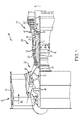
- FIG. 1 schematically illustrates a gas turbine engine 20.
- the gas turbine engine 20 is disclosed herein as a two-spool turbofan that generally incorporates a fan section 22, a compressor section 24, a combustor section 26 and a turbine section 28.
- the fan section 22 drives air along a bypass flow path B in a bypass duct defined within a nacelle 15, while the compressor section 24 drives air along a core or primary flow path C for compression and communication into the combustor section 26 and then expansion through the turbine section 28.
- FIG. 1 schematically illustrates a gas turbine engine 20.
- the gas turbine engine 20 is disclosed herein as a two-spool turbofan that generally incorporates a fan section 22, a compressor section 24, a combustor section 26 and a turbine section 28.
- the fan section 22 drives air along a bypass flow path B in a bypass duct defined within a nacelle 15, while the compressor section 24 drives air along a core or primary flow path C for compression and communication into the combustor section 26 and then expansion
- the gas turbine engine 20 generally includes a low speed spool 30 and a high speed spool 32 mounted for rotation about an engine central longitudinal axis A relative to an engine static structure 36 via several bearing systems 38. It should be understood that various bearing systems at various locations may alternatively or additionally be provided and the location of the several bearing systems 38 may be varied as appropriate to the application.
- the low speed spool 30 generally includes an inner shaft 40 that interconnects a fan 42, a low pressure compressor 44 and a low pressure turbine 46.
- the inner shaft 40 is connected to the fan 42 through a speed change mechanism, which in this gas turbine engine 20 is illustrated as a fan drive gear system 48 configured to drive the fan 42 at a lower speed than the low speed spool 30.
- the high speed spool 32 includes an outer shaft 50 that interconnects a high pressure compressor 52 and a high pressure turbine 54.
- a combustor 56 is arranged in the gas turbine engine 20 between the high pressure compressor 52 and the high pressure turbine 54.
- a mid-turbine frame 57 of the engine static structure 36 is arranged generally between the high pressure turbine 54 and the low pressure turbine 46 and may include airfoils 59 in the core flow path C for guiding the flow into the low pressure turbine 46.
- the mid-turbine frame 57 further supports the several bearing systems 38 in the turbine section 28.
- the inner shaft 40 and the outer shaft 50 are concentric and rotate via the several bearing systems 38 about the engine central longitudinal axis A, which is collinear with longitudinal axes of the inner shaft 40 and the outer shaft 50.
- the air in the core flow path C is compressed by the low pressure compressor 44 and then the high pressure compressor 52, mixed and burned with fuel in the combustor 56, and then expanded over the high pressure turbine 54 and low pressure turbine 46.
- the low pressure turbine 46 and the high pressure turbine 54 rotationally drive the respective low speed spool 30 and the high speed spool 32 in response to the expansion.
- each of the positions of the fan section 22, the compressor section 24, the combustor section 26, the turbine section 28, and the fan drive gear system 48 may be varied.
- the fan drive gear system 48 may be located aft of the combustor section 26 or even aft of the turbine section 28, and the fan section 22 may be positioned forward or aft of the location of the fan drive gear system 48.
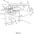
- the system 200 includes a bleed valve 202 having a bleed valve inlet 204 and a bleed valve outlet 206.
- the bleed valve inlet 204 is configured to receive a bleed air from a first access point 208 to the core flow path C.
- the system 200 further includes an air motor 210.
- the air motor 210 includes a first air motor inlet 212 configured to receive the bleed air from the bleed valve outlet 206 and a first air motor outlet 214 configured to exhaust the bleed air.
- the air motor 210 may further include a second air motor inlet 216 configured to receive a pressurized air from a pressurized air source 218 and a second air motor outlet 220 configured to exhaust the pressurized air. While the air motor 210 and the bleed valve 202 are described herein as comprising separate components, the disclosure contemplates incorporation of both components into a single unit.
- the air motor 210 includes an air motor compressor section 222 and an air motor turbine section 224.
- the first air motor inlet 212 is configured to deliver the bleed air to the air motor compressor section 222 and the second air motor inlet 216 is configured to deliver the pressurized air to the air motor turbine section 224.
- the pressurized air may be used to drive the air motor turbine section 224 which, in turn, drives the air motor compressor section 222.
- driving the air motor compressor section 222 serves to pump the bleed air from the first air motor inlet 212 (or from the first access point 208 to the core flow path C) to the first air motor outlet 214.
- the first access point 208 to the core flow path is positioned proximate a core flow path compressor section 230 of the gas turbine engine.
- the core flow path compressor section 230 includes a low pressure section 232 and a high pressure section 234 positioned downstream of the low pressure section 232. Schematically, the low pressure section 232 and the high pressure section 234 may be separated by a dividing line 236 and are each connected, respectively, to corresponding low and high pressure sections of a core air flow path turbine section 238 via corresponding low and high speed spools.
- the core flow path compressor section 230 may include one or more compressor stages 240 (each stage including a rotor section and a stator section).
- the first access point 208 to the core flow path C is positioned proximate a first downstream stage 242 of the high pressure section 234 of the core flow path compressor section 230.
- the pressurized air source 218 is configured to receive the pressurized air from a second access point 244 to the core flow path C positioned proximate a second downstream stage 246 of the high pressure section 234 of the core flow path compressor section 230.
- the second downstream stage 246 is located downstream of the first downstream stage 242 and, thus, contains pressurized air at a higher pressure than is the first downstream stage 242 of the high pressure section 234.
- the first air motor outlet 214 is configured to exhaust the bleed air to a bypass flow path B of the gas turbine engine.
- the second air motor outlet 220 may be configured to exhaust the pressurized air to the bypass flow path B of the gas turbine engine.
- the bleed air may be exhausted to the bypass flow path B via a first conduit 250 configured to expel a bleed air stream 252 and the pressurized air may be exhausted to the bypass flow path B via a second conduit 254 configured to expel a pressurized air stream 256.
- the pressurized air source 218 is configured to receive the pressurized air from a second access point 244 to the core flow path C
- the disclosure is directed to the pressurized air source 218 being configured to receive the pressurized air from an external pneumatic source 260.
- the external pneumatic source comprises one or more of an auxiliary power unit 262 (e.g., an APU positioned on an aircraft) and a ground power unit 264, which may also comprise an auxiliary power unit.
- the disclosure contemplates driving the air motor 210 using an electric motor 290 which, in various embodiments, may be coupled to the air motor compressor section 222 either directly or via a shaft 292. Stated otherwise, the air motor turbine section 224 may be replaced by the electric motor 290.
- use of the electric motor 290 to drive the air motor compressor section 222 may obviate the need for the pressurized air source 218, the second air motor inlet 216, the second air motor outlet 220 and the accompanying conduits for transporting the pressurized air to drive the air motor 210 (the air motor compressor section 222).
- the electric motor 290 and the pressurized air source 218 may be used in conjunction with one another to drive the air motor 210, thereby driving the air motor compressor section 222 to pump bleed air from the compressor section during start-up of the engine.
- the system 200 may include a controller 270, such as, for example, a full authority digital engine control (FADEC).
- the FADEC may be configured, for example, to control opening and closing of the bleed valve 202 and to control opening and closing of a pressurized air valve 272.
- the FADEC may control opening and closing of the pressurized air valve 272, whereby the pressurized air may be conveyed to the bleed valve 202 via a conduit 274 and then used to activate a pressure sensor 276 that is used to control opening and closing of the bleed valve 202.
- the conduit 274 may be replaced by an electrical line configured to carry a charge or data used to trigger a solenoid configured to open and close the bleed valve 202.
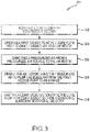
- the gas turbine engine has a core flow path compressor section, a combustor section and a core flow path turbine section configured to provide for a core flow path C extending through the gas turbine engine.
- the method 300 includes a first step 302 of rotating the core flow path compressor section and the core flow path turbine section. The rotation may be accomplished, in various embodiments, by a starter motor or the like.
- a second step 304 includes opening a first access point to the core flow path C to direct a bleed air from the core flow compressor section to an air motor compressor section of an air motor.
- a third step 306 includes directing a pressurized air from a pressurized air source to an air motor turbine section of the air motor.
- a fourth step 308 includes driving the air motor turbine section using the pressurized air to drive the air motor compressor section to pump the bleed air from the first access point to an exhaust.
- a fifth step 310 includes igniting the combustor section once the core flow path compressor section and the core flow path turbine section have reached sufficient rotational velocity.
- references to “one embodiment,” “an embodiment,” “various embodiments,” etc. indicate that the embodiment described may include a particular feature, structure, or characteristic, but every embodiment may not necessarily include the particular feature, structure, or characteristic. Moreover, such phrases are not necessarily referring to the same embodiment.
- the terms “comprises,” “comprising,” or any other variation thereof are intended to cover a non-exclusive inclusion, such that a process, method, article, or apparatus that comprises a list of elements does not include only those elements but may include other elements not expressly listed or inherent to such process, method, article, or apparatus.
Landscapes
- Engineering & Computer Science (AREA)
- Mechanical Engineering (AREA)
- General Engineering & Computer Science (AREA)
- Chemical & Material Sciences (AREA)
- Combustion & Propulsion (AREA)
- Life Sciences & Earth Sciences (AREA)
- Sustainable Development (AREA)
- Physics & Mathematics (AREA)
- Fluid Mechanics (AREA)
- Structures Of Non-Positive Displacement Pumps (AREA)
Description
- The present disclosure relates generally to gas turbine engines and, more particularly, to apparatus and methods used to assist start-up of gas turbine engines.
- Gas turbine engines, such as those used to power modern commercial and military aircraft, typically include a fan section, a compressor section, a combustor section and a turbine section. During operation, air is pressurized in the compressor section and mixed with fuel and burned in the combustor section to generate hot combustion gases. The hot combustion gases are then communicated through the turbine section, which extracts energy from the gases to power the compressor section, the fan section and various other loads occurring within or proximate the gas turbine engine. Many engine configurations split the compressor section and the turbine section into high pressure and speed sections and low pressure and speed sections, each having blades mounted on respective high speed and low speed spools. A typical engine core flow path extends sequentially through the low compressor section, the high compressor section, the combustor section, the high turbine section and the low turbine section.
- At start-up, the turbine section of the gas turbine engine has not begun to fully provide power. Thus, driving the compressor section may be more challenging than it will generally be at steady state or design conditions. Accordingly, gas turbine engines may include one or more bleed valves to bleed air away from the core flow path at the compressor section during start-up and thereby reduce the load required to drive the compressor.
-
US 2017/268423 A1 describes a bleed control system for a gas turbine engine of an aircraft. -
US 2018/163627 A1 describes an engine driven environmental control system air circuit. -
US 2014/250898 A1 describes bleed air systems for use with aircrafts and related methods. - From a first aspect of the invention, there is provided a system for bleeding air from a core flow path of a gas turbine engine as recited in claim 1.
- In various embodiments, the compressor section includes a high pressure section and a low pressure section and the first access point to the core flow path is positioned proximate the high pressure section. In various embodiments, the first access point to the core flow path is positioned proximate a first downstream stage of the high pressure section.
- In various embodiments, the first air motor outlet is configured to exhaust the bleed air to a bypass flow path of the gas turbine engine. In various embodiments, the second air motor outlet is configured to exhaust the pressurized air to the bypass flow path of the gas turbine engine.
- In various embodiments, the air motor includes an air motor compressor section and an air motor turbine section. In various embodiments, the first air motor inlet is configured to deliver the bleed air to the air motor compressor section and the second air motor inlet is configured to deliver the pressurized air to the air motor turbine section.
- In various embodiments, the first access point to the core flow path is positioned proximate a core flow path compressor section of the gas turbine engine. In various embodiments, the first access point to the core flow path is positioned proximate a first downstream stage of a high pressure section of the core flow path compressor section. In various embodiments, the air motor is driven by a pressurized air source or an electric motor.
- A gas turbine engine is disclosed. In various embodiments, the gas turbine engine includes a compressor section, a combustor section and a turbine section configured to provide for a core flow path extending through the gas turbine engine; a bleed valve having a bleed valve inlet configured to receive a bleed air from a first access point to the core flow path and a bleed valve outlet; and an air motor having a first air motor inlet configured to receive the bleed air from the bleed valve outlet and a first air motor outlet configured to exhaust the bleed air, the air motor configured to pump the bleed air from the core flow path of the gas turbine engine.
- In various embodiments, a second air motor inlet is configured to receive a pressurized air from a pressurized air source and a second air motor outlet is configured to exhaust the pressurized air, the compressor section includes a high pressure section and a low pressure section and the first access point to the core flow path is positioned proximate a first downstream stage of the high pressure section.
- In various embodiments, the air motor includes an air motor compressor section and an air motor turbine section, wherein the first air motor inlet is configured to deliver the bleed air to the air motor compressor section and the second air motor inlet is configured to deliver the pressurized air to the air motor turbine section, and wherein the first air motor outlet is configured to exhaust the bleed air to a bypass flow path of the gas turbine engine and the second air motor outlet is configured to exhaust the pressurized air to the bypass flow path.
- A method of starting a gas turbine engine having a core flow path compressor section, a combustor section and a core flow path turbine section configured to provide for a core flow path extending through the gas turbine engine is disclosed. In various embodiments, the method includes the steps of rotating the core flow path compressor section and the core flow path turbine section; opening a first access point to the core flow path to direct a bleed air from the core flow compressor section to an air motor compressor section of an air motor; directing a pressurized air from a pressurized air source to an air motor turbine section of the air motor; driving the air motor turbine section using the pressurized air to drive the air motor compressor section to pump the bleed air from the first access point; and igniting the combustor section.
- The subject matter of the present disclosure is particularly pointed out and distinctly claimed in the concluding portion of the specification. A more complete understanding of the present disclosure, however, may best be obtained by referring to the following detailed description and claims in connection with the following drawings. While the drawings illustrate various embodiments employing the principles described herein, the drawings do not limit the scope of the claims.
-
FIG. 1 is a schematic view of a gas turbine engine, in accordance with various embodiments; -
FIG. 2 is a schematic view of a power assisted bleed system, in accordance with various embodiments; and -
FIG. 3 described a method of starting a gas turbine engine, in accordance with various embodiments. - The following detailed description of various embodiments herein makes reference to the accompanying drawings, which show various embodiments by way of illustration. While these various embodiments are described in sufficient detail to enable those skilled in the art to practice the disclosure, it should be understood that other embodiments may be realized and that changes may be made without departing from the scope of the disclosure. Thus, the detailed description herein is presented for purposes of illustration only and not of limitation. Furthermore, any reference to singular includes plural embodiments, and any reference to more than one component or step may include a singular embodiment or step. Also, any reference to attached, fixed, connected, or the like may include permanent, removable, temporary, partial, full or any other possible attachment option. Additionally, any reference to without contact (or similar phrases) may also include reduced contact or minimal contact. It should also be understood that unless specifically stated otherwise, references to "a," "an" or "the" may include one or more than one and that reference to an item in the singular may also include the item in the plural. Further, all ranges may include upper and lower values and all ranges and ratio limits disclosed herein may be combined.
- Referring now to the drawings,
FIG. 1 schematically illustrates agas turbine engine 20. Thegas turbine engine 20 is disclosed herein as a two-spool turbofan that generally incorporates afan section 22, acompressor section 24, acombustor section 26 and aturbine section 28. Thefan section 22 drives air along a bypass flow path B in a bypass duct defined within anacelle 15, while thecompressor section 24 drives air along a core or primary flow path C for compression and communication into thecombustor section 26 and then expansion through theturbine section 28. Although depicted as a two-spool turbofan gas turbine engine in the disclosed non-limiting embodiment, it should be understood that the concepts described herein are not limited to use with two-spool turbofans as the teachings may be applied to other types of turbine engines. - The
gas turbine engine 20 generally includes alow speed spool 30 and ahigh speed spool 32 mounted for rotation about an engine central longitudinal axis A relative to an enginestatic structure 36 viaseveral bearing systems 38. It should be understood that various bearing systems at various locations may alternatively or additionally be provided and the location of theseveral bearing systems 38 may be varied as appropriate to the application. Thelow speed spool 30 generally includes aninner shaft 40 that interconnects afan 42, alow pressure compressor 44 and alow pressure turbine 46. Theinner shaft 40 is connected to thefan 42 through a speed change mechanism, which in thisgas turbine engine 20 is illustrated as a fan drive gear system 48 configured to drive thefan 42 at a lower speed than thelow speed spool 30. Thehigh speed spool 32 includes anouter shaft 50 that interconnects ahigh pressure compressor 52 and ahigh pressure turbine 54. Acombustor 56 is arranged in thegas turbine engine 20 between thehigh pressure compressor 52 and thehigh pressure turbine 54. A mid-turbine frame 57 of the enginestatic structure 36 is arranged generally between thehigh pressure turbine 54 and thelow pressure turbine 46 and may includeairfoils 59 in the core flow path C for guiding the flow into thelow pressure turbine 46. The mid-turbine frame 57 further supports theseveral bearing systems 38 in theturbine section 28. Theinner shaft 40 and theouter shaft 50 are concentric and rotate via theseveral bearing systems 38 about the engine central longitudinal axis A, which is collinear with longitudinal axes of theinner shaft 40 and theouter shaft 50. - The air in the core flow path C is compressed by the
low pressure compressor 44 and then thehigh pressure compressor 52, mixed and burned with fuel in thecombustor 56, and then expanded over thehigh pressure turbine 54 andlow pressure turbine 46. Thelow pressure turbine 46 and thehigh pressure turbine 54 rotationally drive the respectivelow speed spool 30 and thehigh speed spool 32 in response to the expansion. It will be appreciated that each of the positions of thefan section 22, thecompressor section 24, thecombustor section 26, theturbine section 28, and the fan drive gear system 48 may be varied. For example, the fan drive gear system 48 may be located aft of thecombustor section 26 or even aft of theturbine section 28, and thefan section 22 may be positioned forward or aft of the location of the fan drive gear system 48. - Referring now to
FIG. 2 , a schematic view of asystem 200 for bleeding air from a core flow path C of a gas turbine engine, such as, for example, thegas turbine engine 20 described above with reference toFIG. 1 , is provided. In various embodiments, thesystem 200 includes ableed valve 202 having ableed valve inlet 204 and ableed valve outlet 206. Thebleed valve inlet 204 is configured to receive a bleed air from afirst access point 208 to the core flow path C. Thesystem 200 further includes anair motor 210. In various embodiments, theair motor 210 includes a firstair motor inlet 212 configured to receive the bleed air from thebleed valve outlet 206 and a first air motor outlet 214 configured to exhaust the bleed air. Theair motor 210 may further include a secondair motor inlet 216 configured to receive a pressurized air from apressurized air source 218 and a secondair motor outlet 220 configured to exhaust the pressurized air. While theair motor 210 and thebleed valve 202 are described herein as comprising separate components, the disclosure contemplates incorporation of both components into a single unit. - In various embodiments, the
air motor 210 includes an airmotor compressor section 222 and an airmotor turbine section 224. In various embodiments, the firstair motor inlet 212 is configured to deliver the bleed air to the airmotor compressor section 222 and the secondair motor inlet 216 is configured to deliver the pressurized air to the airmotor turbine section 224. With such an arrangement, the pressurized air may be used to drive the airmotor turbine section 224 which, in turn, drives the airmotor compressor section 222. In various embodiments, driving the airmotor compressor section 222 serves to pump the bleed air from the first air motor inlet 212 (or from thefirst access point 208 to the core flow path C) to the first air motor outlet 214. - In various embodiments, the
first access point 208 to the core flow path is positioned proximate a core flowpath compressor section 230 of the gas turbine engine. In various embodiments, the core flowpath compressor section 230 includes a low pressure section 232 and ahigh pressure section 234 positioned downstream of the low pressure section 232. Schematically, the low pressure section 232 and thehigh pressure section 234 may be separated by adividing line 236 and are each connected, respectively, to corresponding low and high pressure sections of a core air flowpath turbine section 238 via corresponding low and high speed spools. In various embodiments, the core flowpath compressor section 230 may include one or more compressor stages 240 (each stage including a rotor section and a stator section). - In various embodiments, the
first access point 208 to the core flow path C is positioned proximate a firstdownstream stage 242 of thehigh pressure section 234 of the core flowpath compressor section 230. In various embodiments that fall outside the scope of the present invention, thepressurized air source 218 is configured to receive the pressurized air from asecond access point 244 to the core flow path C positioned proximate a seconddownstream stage 246 of thehigh pressure section 234 of the core flowpath compressor section 230. In various embodiments, the seconddownstream stage 246 is located downstream of the firstdownstream stage 242 and, thus, contains pressurized air at a higher pressure than is the firstdownstream stage 242 of thehigh pressure section 234. - In various embodiments, the first air motor outlet 214 is configured to exhaust the bleed air to a bypass flow path B of the gas turbine engine. In similar fashion, the second
air motor outlet 220 may be configured to exhaust the pressurized air to the bypass flow path B of the gas turbine engine. In various embodiments, the bleed air may be exhausted to the bypass flow path B via afirst conduit 250 configured to expel ableed air stream 252 and the pressurized air may be exhausted to the bypass flow path B via asecond conduit 254 configured to expel apressurized air stream 256. - While the foregoing describes the
pressurized air source 218 as being configured to receive the pressurized air from asecond access point 244 to the core flow path C, the disclosure is directed to thepressurized air source 218 being configured to receive the pressurized air from an externalpneumatic source 260. The external pneumatic source comprises one or more of an auxiliary power unit 262 (e.g., an APU positioned on an aircraft) and aground power unit 264, which may also comprise an auxiliary power unit. In addition, while the foregoing describes use of a pressurized air to drive theair motor 210, thereby pumping the bleed air from the first air motor inlet 212 (or from thefirst access point 208 to the core flow path C) to the first air motor outlet 214, the disclosure contemplates driving theair motor 210 using anelectric motor 290 which, in various embodiments, may be coupled to the airmotor compressor section 222 either directly or via ashaft 292. Stated otherwise, the airmotor turbine section 224 may be replaced by theelectric motor 290. Further, in various embodiments, use of theelectric motor 290 to drive the airmotor compressor section 222 may obviate the need for thepressurized air source 218, the secondair motor inlet 216, the secondair motor outlet 220 and the accompanying conduits for transporting the pressurized air to drive the air motor 210 (the air motor compressor section 222). Alternatively, in various embodiments, theelectric motor 290 and thepressurized air source 218 may be used in conjunction with one another to drive theair motor 210, thereby driving the airmotor compressor section 222 to pump bleed air from the compressor section during start-up of the engine. - In various embodiments, the
system 200 may include acontroller 270, such as, for example, a full authority digital engine control (FADEC). The FADEC may be configured, for example, to control opening and closing of thebleed valve 202 and to control opening and closing of apressurized air valve 272. In various embodiments, the FADEC may control opening and closing of thepressurized air valve 272, whereby the pressurized air may be conveyed to thebleed valve 202 via aconduit 274 and then used to activate apressure sensor 276 that is used to control opening and closing of thebleed valve 202. In various embodiments, theconduit 274 may be replaced by an electrical line configured to carry a charge or data used to trigger a solenoid configured to open and close thebleed valve 202. - Referring now to
FIG. 3 , amethod 300 of starting a gas turbine engine is disclosed. In various embodiments, the gas turbine engine has a core flow path compressor section, a combustor section and a core flow path turbine section configured to provide for a core flow path C extending through the gas turbine engine. In various embodiments, themethod 300 includes afirst step 302 of rotating the core flow path compressor section and the core flow path turbine section. The rotation may be accomplished, in various embodiments, by a starter motor or the like. Asecond step 304 includes opening a first access point to the core flow path C to direct a bleed air from the core flow compressor section to an air motor compressor section of an air motor. Athird step 306 includes directing a pressurized air from a pressurized air source to an air motor turbine section of the air motor. Afourth step 308 includes driving the air motor turbine section using the pressurized air to drive the air motor compressor section to pump the bleed air from the first access point to an exhaust. Afifth step 310 includes igniting the combustor section once the core flow path compressor section and the core flow path turbine section have reached sufficient rotational velocity. - Benefits, other advantages, and solutions to problems have been described herein with regard to specific embodiments. Furthermore, the connecting lines shown in the various figures contained herein are intended to represent exemplary functional relationships and/or physical couplings between the various elements. It should be noted that many alternative or additional functional relationships or physical connections may be present in a practical system. However, the benefits, advantages, solutions to problems, and any elements that may cause any benefit, advantage, or solution to occur or become more pronounced are not to be construed as critical, required, or essential features or elements of the disclosure. The scope of the disclosure is accordingly to be limited by nothing other than the appended claims, in which reference to an element in the singular is not intended to mean "one and only one" unless explicitly so stated, but rather "one or more." Moreover, where a phrase similar to "at least one of A, B, or C" is used in the claims, it is intended that the phrase be interpreted to mean that A alone may be present in an embodiment, B alone may be present in an embodiment, C alone may be present in an embodiment, or that any combination of the elements A, B and C may be present in a single embodiment; for example, A and B, A and C, B and C, or A and B and C. Different cross-hatching is used throughout the figures to denote different parts but not necessarily to denote the same or different materials.
- Systems, methods and apparatus are provided herein. In the detailed description herein, references to "one embodiment," "an embodiment," "various embodiments," etc., indicate that the embodiment described may include a particular feature, structure, or characteristic, but every embodiment may not necessarily include the particular feature, structure, or characteristic. Moreover, such phrases are not necessarily referring to the same embodiment. As used herein, the terms "comprises," "comprising," or any other variation thereof, are intended to cover a non-exclusive inclusion, such that a process, method, article, or apparatus that comprises a list of elements does not include only those elements but may include other elements not expressly listed or inherent to such process, method, article, or apparatus.
- Finally, it should be understood that any of the above described concepts can be used alone or in combination with any or all of the other above described concepts. Although various embodiments have been disclosed and described, one of ordinary skill in this art would recognize that certain modifications would come within the scope of the invention. Accordingly, the description is not intended to be exhaustive or to limit the principles described or illustrated herein to any precise form. Many modifications and variations falling within the scope of the claims are possible in light of the above teaching.
Claims (15)
- A system for bleeding air from a core flow path (C) of a gas turbine engine (20), comprising:a bleed valve (202) having a bleed valve inlet (204) configured to receive a bleed air from a first access point (208) to the core flow path (C) and a bleed valve outlet (206);an air motor (210) having a first air motor inlet (212) configured to receive the bleed air from the bleed valve outlet (206) and a first air motor outlet (214) configured to exhaust the bleed air, the air motor (210) configured to pump the bleed air from the core flow path (C) of the gas turbine engine (20),the system further comprising a pressurized air source (218),wherein the air motor (210) further comprises a second air motor inlet (216) configured to receive a pressurized air from said pressurized air source (218) and a second air motor outlet (220) configured to exhaust the pressurized air and wherein the first access point (208) to the core flow path (C) is positioned proximate a compressor section (24; 230) of the gas turbine engine (20), andcharacterised in that the pressurized air source (218) comprises an external pneumatic source (260) that includes at least one of an auxiliary power unit (262) and a ground power unit (264).
- The system of claim 1, wherein the compressor section (24; 230) includes a high pressure section (52; 234) and a low pressure section (44; 232) and wherein the first access point (208) to the core flow path (C) is positioned proximate the high pressure section (52; 234).
- The system of claim 2, wherein the first access point (208) to the core flow path (C) is positioned proximate a first downstream stage of the high pressure section (52; 234).
- The system of any preceding claim, wherein the first air motor outlet (214) is configured to exhaust the bleed air to a bypass flow path (B) of the gas turbine engine (20).
- The system of any preceding claim, wherein the second air motor outlet (220) is configured to exhaust the pressurized air to the bypass flow path (B) of the gas turbine engine (20).
- The system of any preceding claim, wherein the air motor (210) includes an air motor compressor section (222) and an air motor turbine section (224).
- The system of claim 6, wherein the first air motor inlet (212) is configured to deliver the bleed air to the air motor compressor section (222) and the second air motor inlet (216) is configured to deliver the pressurized air to the air motor turbine section (224).
- The system of claim 7, wherein the first access point (208) to the core flow path (C) is positioned proximate a core flow path compressor section of the gas turbine engine (20).
- The system of claim 8, wherein the first access point (208) to the core flow path (C) is positioned proximate a first downstream stage of a high pressure section (52; 234) of the core flow path compressor section.
- The system of any preceding claim, wherein the air motor (210) is driven by the pressurized air source (218).
- The system of any preceding claim, wherein the air motor (210) is driven by an electric motor.
- A gas turbine engine (20), comprising:a compressor section (24; 230), a combustor section (26) and a turbine section (28) configured to provide for a core flow path (C) extending through the gas turbine engine (20); anda system as claimed in claim 1.
- The gas turbine engine (20) of claim 12, wherein the compressor section (24; 230) includes a high pressure section (52; 234) and a low pressure section (44; 232) and wherein the first access point (208) to the core flow path (C) is positioned proximate a first downstream stage of the high pressure section (52; 234).
- The gas turbine engine (20) of claim 13, wherein the air motor (210) includes an air motor compressor section (222) and an air motor turbine section (224), wherein the first air motor inlet (212) is configured to deliver the bleed air to the air motor compressor section (222) and the second air motor inlet (216) is configured to deliver the pressurized air to the air motor turbine section (224), and wherein the first air motor outlet (214) is configured to exhaust the bleed air to a bypass flow path (B) of the gas turbine engine (20) and the second air motor outlet (220) is configured to exhaust the pressurized air to the bypass flow path (B).
- A method of starting a gas turbine engine (20) having a core flow path compressor section, a combustor section (26) and a core flow path turbine section configured to provide for a core flow path (C) extending through the gas turbine engine (20), comprising:rotating the core flow path compressor section and the core flow path turbine section;opening a first access point (208) to the core flow path (C) to direct a bleed air from the core flow compressor section to an air motor compressor section (222) of an air motor (210);directing a pressurized air from a pressurized air source (218) to an air motor turbine section (224) of the air motor (210);driving the air motor turbine section (224) using the pressurized air to drive the air motor compressor section (222) to pump the bleed air from the first access point (208); andigniting the combustor section (26).
Applications Claiming Priority (2)
| Application Number | Priority Date | Filing Date | Title |
|---|---|---|---|
| US201962801296P | 2019-02-05 | 2019-02-05 | |
| US16/654,202 US11454175B2 (en) | 2019-02-05 | 2019-10-16 | Power assisted engine start bleed system |
Publications (2)
| Publication Number | Publication Date |
|---|---|
| EP3693572A1 EP3693572A1 (en) | 2020-08-12 |
| EP3693572B1 true EP3693572B1 (en) | 2022-12-28 |
Family
ID=69172732
Family Applications (1)
| Application Number | Title | Priority Date | Filing Date |
|---|---|---|---|
| EP20152032.7A Active EP3693572B1 (en) | 2019-02-05 | 2020-01-15 | Power assisted engine start bleed system |
Country Status (2)
| Country | Link |
|---|---|
| US (2) | US11454175B2 (en) |
| EP (1) | EP3693572B1 (en) |
Cited By (1)
| Publication number | Priority date | Publication date | Assignee | Title |
|---|---|---|---|---|
| EP4495403A1 (en) * | 2023-07-21 | 2025-01-22 | RTX Corporation | Buffer air assembly for an aircraft engine |
Families Citing this family (10)
| Publication number | Priority date | Publication date | Assignee | Title |
|---|---|---|---|---|
| US11008949B2 (en) * | 2018-09-25 | 2021-05-18 | Pratt & Whitney Canada Corp. | Multi-source air system and switching valve assembly for a gas turbine engine |
| US11274599B2 (en) | 2019-03-27 | 2022-03-15 | Pratt & Whitney Canada Corp. | Air system switching system to allow aero-engines to operate in standby mode |
| US11391219B2 (en) | 2019-04-18 | 2022-07-19 | Pratt & Whitney Canada Corp. | Health monitor for air switching system |
| US11274611B2 (en) | 2019-05-31 | 2022-03-15 | Pratt & Whitney Canada Corp. | Control logic for gas turbine engine fuel economy |
| US11859563B2 (en) | 2019-05-31 | 2024-01-02 | Pratt & Whitney Canada Corp. | Air system of multi-engine aircraft |
| US11326525B2 (en) | 2019-10-11 | 2022-05-10 | Pratt & Whitney Canada Corp. | Aircraft bleed air systems and methods |
| US11939984B2 (en) * | 2021-04-29 | 2024-03-26 | The Boeing Company | Compressors having multi-speed gearboxes |
| US12104690B2 (en) | 2021-08-03 | 2024-10-01 | The Boeing Company | Epicyclic gear carrier assembly having an integrated lubrication pump |
| US11788465B2 (en) * | 2022-01-19 | 2023-10-17 | General Electric Company | Bleed flow assembly for a gas turbine engine |
| US12378893B2 (en) * | 2023-07-21 | 2025-08-05 | Rtx Corporation | Buffer air assembly for an aircraft engine |
Family Cites Families (13)
| Publication number | Priority date | Publication date | Assignee | Title |
|---|---|---|---|---|
| US5363641A (en) * | 1993-08-06 | 1994-11-15 | United Technologies Corporation | Integrated auxiliary power system |
| US6305156B1 (en) * | 1999-09-03 | 2001-10-23 | Alliedsignal Inc. | Integrated bleed air and engine starting system |
| US8955794B2 (en) | 2012-01-24 | 2015-02-17 | The Boeing Company | Bleed air systems for use with aircrafts and related methods |
| GB201319563D0 (en) * | 2013-11-06 | 2013-12-18 | Rolls Royce Plc | Pneumatic system for an aircraft |
| US9810158B2 (en) * | 2014-04-01 | 2017-11-07 | The Boeing Company | Bleed air systems for use with aircraft and related methods |
| US10077720B2 (en) | 2015-04-17 | 2018-09-18 | Honda Motor Co., Ltd. | Control apparatus for a gas-turbine aeroengine |
| US20170241340A1 (en) * | 2016-02-19 | 2017-08-24 | United Technologies Corporation | Turbocompressor for aircraft environmental control system |
| US11473497B2 (en) | 2016-03-15 | 2022-10-18 | Hamilton Sundstrand Corporation | Engine bleed system with motorized compressor |
| US10519963B2 (en) * | 2016-06-20 | 2019-12-31 | United Technologies Corporation | Engine bleed air system with waste gate valve for compressor surge management |
| US20180009536A1 (en) * | 2016-07-11 | 2018-01-11 | General Electric Company | Bleed flow extraction system for a gas turbine engine |
| US20180162537A1 (en) | 2016-12-09 | 2018-06-14 | United Technologies Corporation | Environmental control system air circuit |
| CN207161216U (en) | 2017-08-17 | 2018-03-30 | 俞平 | The gas compressor system of supercharger among a kind of band |
| US10954865B2 (en) * | 2018-06-19 | 2021-03-23 | The Boeing Company | Pressurized air systems for aircraft and related methods |
-
2019
- 2019-10-16 US US16/654,202 patent/US11454175B2/en active Active
-
2020
- 2020-01-15 EP EP20152032.7A patent/EP3693572B1/en active Active
-
2022
- 2022-08-23 US US17/893,640 patent/US11815029B2/en active Active
Cited By (1)
| Publication number | Priority date | Publication date | Assignee | Title |
|---|---|---|---|---|
| EP4495403A1 (en) * | 2023-07-21 | 2025-01-22 | RTX Corporation | Buffer air assembly for an aircraft engine |
Also Published As
| Publication number | Publication date |
|---|---|
| US11815029B2 (en) | 2023-11-14 |
| EP3693572A1 (en) | 2020-08-12 |
| US20200248627A1 (en) | 2020-08-06 |
| US20230148411A1 (en) | 2023-05-11 |
| US11454175B2 (en) | 2022-09-27 |
Similar Documents
| Publication | Publication Date | Title |
|---|---|---|
| EP3693572B1 (en) | Power assisted engine start bleed system | |
| US11585354B2 (en) | Engine having variable pitch outlet guide vanes | |
| EP3569842B1 (en) | Electrically driven cooled cooling air system | |
| US11952947B2 (en) | Hybrid electric fan with stall free low pressure compressor | |
| US11873766B2 (en) | Differential geared amplification of auxiliary power unit | |
| US8887485B2 (en) | Three spool gas turbine engine having a clutch and compressor bypass | |
| US9657643B2 (en) | Energy efficient pump system | |
| EP2932073B1 (en) | Turbo compressor for bleed air | |
| US10337405B2 (en) | Method and system for bowed rotor start mitigation using rotor cooling | |
| CN113153526A (en) | Mixed Flow Turbine Core | |
| EP4177449B1 (en) | Accessory gearbox with superposition gearbox | |
| EP3321490B1 (en) | Turbo-generator based bleed air system | |
| US10890115B2 (en) | Low torque engine starting with dual spool power extraction with superposition gearbox | |
| EP3056714B1 (en) | Intercooled cooling air system using cooling compressor as starter | |
| US12497918B2 (en) | Turbine engine with inverse Brayton cycle | |
| US12320299B2 (en) | Cooling air delivery system and methods thereof | |
| EP3524795A1 (en) | Axial compressor with inter-stage centrifugal compressor | |
| US12392296B2 (en) | Powerplant with multiple integrated gas turbine engines | |
| US20260063196A1 (en) | Gearbox assembly having a segmented scavenge gutter for a turbine engine |
Legal Events
| Date | Code | Title | Description |
|---|---|---|---|
| PUAI | Public reference made under article 153(3) epc to a published international application that has entered the european phase |
Free format text: ORIGINAL CODE: 0009012 |
|
| STAA | Information on the status of an ep patent application or granted ep patent |
Free format text: STATUS: THE APPLICATION HAS BEEN PUBLISHED |
|
| AK | Designated contracting states |
Kind code of ref document: A1 Designated state(s): AL AT BE BG CH CY CZ DE DK EE ES FI FR GB GR HR HU IE IS IT LI LT LU LV MC MK MT NL NO PL PT RO RS SE SI SK SM TR |
|
| AX | Request for extension of the european patent |
Extension state: BA ME |
|
| STAA | Information on the status of an ep patent application or granted ep patent |
Free format text: STATUS: REQUEST FOR EXAMINATION WAS MADE |
|
| 17P | Request for examination filed |
Effective date: 20210212 |
|
| RAP1 | Party data changed (applicant data changed or rights of an application transferred) |
Owner name: RAYTHEON TECHNOLOGIES CORPORATION |
|
| RBV | Designated contracting states (corrected) |
Designated state(s): AL AT BE BG CH CY CZ DE DK EE ES FI FR GB GR HR HU IE IS IT LI LT LU LV MC MK MT NL NO PL PT RO RS SE SI SK SM TR |
|
| GRAP | Despatch of communication of intention to grant a patent |
Free format text: ORIGINAL CODE: EPIDOSNIGR1 |
|
| STAA | Information on the status of an ep patent application or granted ep patent |
Free format text: STATUS: GRANT OF PATENT IS INTENDED |
|
| INTG | Intention to grant announced |
Effective date: 20220721 |
|
| GRAS | Grant fee paid |
Free format text: ORIGINAL CODE: EPIDOSNIGR3 |
|
| GRAA | (expected) grant |
Free format text: ORIGINAL CODE: 0009210 |
|
| STAA | Information on the status of an ep patent application or granted ep patent |
Free format text: STATUS: THE PATENT HAS BEEN GRANTED |
|
| AK | Designated contracting states |
Kind code of ref document: B1 Designated state(s): AL AT BE BG CH CY CZ DE DK EE ES FI FR GB GR HR HU IE IS IT LI LT LU LV MC MK MT NL NO PL PT RO RS SE SI SK SM TR |
|
| REG | Reference to a national code |
Ref country code: GB Ref legal event code: FG4D |
|
| REG | Reference to a national code |
Ref country code: CH Ref legal event code: EP |
|
| REG | Reference to a national code |
Ref country code: DE Ref legal event code: R096 Ref document number: 602020007125 Country of ref document: DE |
|
| REG | Reference to a national code |
Ref country code: AT Ref legal event code: REF Ref document number: 1540633 Country of ref document: AT Kind code of ref document: T Effective date: 20230115 |
|
| REG | Reference to a national code |
Ref country code: IE Ref legal event code: FG4D |
|
| REG | Reference to a national code |
Ref country code: LT Ref legal event code: MG9D |
|
| PG25 | Lapsed in a contracting state [announced via postgrant information from national office to epo] |
Ref country code: SE Free format text: LAPSE BECAUSE OF FAILURE TO SUBMIT A TRANSLATION OF THE DESCRIPTION OR TO PAY THE FEE WITHIN THE PRESCRIBED TIME-LIMIT Effective date: 20221228 Ref country code: NO Free format text: LAPSE BECAUSE OF FAILURE TO SUBMIT A TRANSLATION OF THE DESCRIPTION OR TO PAY THE FEE WITHIN THE PRESCRIBED TIME-LIMIT Effective date: 20230328 Ref country code: LT Free format text: LAPSE BECAUSE OF FAILURE TO SUBMIT A TRANSLATION OF THE DESCRIPTION OR TO PAY THE FEE WITHIN THE PRESCRIBED TIME-LIMIT Effective date: 20221228 Ref country code: FI Free format text: LAPSE BECAUSE OF FAILURE TO SUBMIT A TRANSLATION OF THE DESCRIPTION OR TO PAY THE FEE WITHIN THE PRESCRIBED TIME-LIMIT Effective date: 20221228 |
|
| REG | Reference to a national code |
Ref country code: NL Ref legal event code: MP Effective date: 20221228 |
|
| REG | Reference to a national code |
Ref country code: AT Ref legal event code: MK05 Ref document number: 1540633 Country of ref document: AT Kind code of ref document: T Effective date: 20221228 |
|
| PG25 | Lapsed in a contracting state [announced via postgrant information from national office to epo] |
Ref country code: RS Free format text: LAPSE BECAUSE OF FAILURE TO SUBMIT A TRANSLATION OF THE DESCRIPTION OR TO PAY THE FEE WITHIN THE PRESCRIBED TIME-LIMIT Effective date: 20221228 Ref country code: LV Free format text: LAPSE BECAUSE OF FAILURE TO SUBMIT A TRANSLATION OF THE DESCRIPTION OR TO PAY THE FEE WITHIN THE PRESCRIBED TIME-LIMIT Effective date: 20221228 Ref country code: HR Free format text: LAPSE BECAUSE OF FAILURE TO SUBMIT A TRANSLATION OF THE DESCRIPTION OR TO PAY THE FEE WITHIN THE PRESCRIBED TIME-LIMIT Effective date: 20221228 Ref country code: GR Free format text: LAPSE BECAUSE OF FAILURE TO SUBMIT A TRANSLATION OF THE DESCRIPTION OR TO PAY THE FEE WITHIN THE PRESCRIBED TIME-LIMIT Effective date: 20230329 |
|
| P01 | Opt-out of the competence of the unified patent court (upc) registered |
Effective date: 20230521 |
|
| PG25 | Lapsed in a contracting state [announced via postgrant information from national office to epo] |
Ref country code: NL Free format text: LAPSE BECAUSE OF FAILURE TO SUBMIT A TRANSLATION OF THE DESCRIPTION OR TO PAY THE FEE WITHIN THE PRESCRIBED TIME-LIMIT Effective date: 20221228 |
|
| PG25 | Lapsed in a contracting state [announced via postgrant information from national office to epo] |
Ref country code: SM Free format text: LAPSE BECAUSE OF FAILURE TO SUBMIT A TRANSLATION OF THE DESCRIPTION OR TO PAY THE FEE WITHIN THE PRESCRIBED TIME-LIMIT Effective date: 20221228 Ref country code: RO Free format text: LAPSE BECAUSE OF FAILURE TO SUBMIT A TRANSLATION OF THE DESCRIPTION OR TO PAY THE FEE WITHIN THE PRESCRIBED TIME-LIMIT Effective date: 20221228 Ref country code: PT Free format text: LAPSE BECAUSE OF FAILURE TO SUBMIT A TRANSLATION OF THE DESCRIPTION OR TO PAY THE FEE WITHIN THE PRESCRIBED TIME-LIMIT Effective date: 20230428 Ref country code: ES Free format text: LAPSE BECAUSE OF FAILURE TO SUBMIT A TRANSLATION OF THE DESCRIPTION OR TO PAY THE FEE WITHIN THE PRESCRIBED TIME-LIMIT Effective date: 20221228 Ref country code: EE Free format text: LAPSE BECAUSE OF FAILURE TO SUBMIT A TRANSLATION OF THE DESCRIPTION OR TO PAY THE FEE WITHIN THE PRESCRIBED TIME-LIMIT Effective date: 20221228 Ref country code: CZ Free format text: LAPSE BECAUSE OF FAILURE TO SUBMIT A TRANSLATION OF THE DESCRIPTION OR TO PAY THE FEE WITHIN THE PRESCRIBED TIME-LIMIT Effective date: 20221228 Ref country code: AT Free format text: LAPSE BECAUSE OF FAILURE TO SUBMIT A TRANSLATION OF THE DESCRIPTION OR TO PAY THE FEE WITHIN THE PRESCRIBED TIME-LIMIT Effective date: 20221228 |
|
| PG25 | Lapsed in a contracting state [announced via postgrant information from national office to epo] |
Ref country code: SK Free format text: LAPSE BECAUSE OF FAILURE TO SUBMIT A TRANSLATION OF THE DESCRIPTION OR TO PAY THE FEE WITHIN THE PRESCRIBED TIME-LIMIT Effective date: 20221228 Ref country code: PL Free format text: LAPSE BECAUSE OF FAILURE TO SUBMIT A TRANSLATION OF THE DESCRIPTION OR TO PAY THE FEE WITHIN THE PRESCRIBED TIME-LIMIT Effective date: 20221228 Ref country code: IS Free format text: LAPSE BECAUSE OF FAILURE TO SUBMIT A TRANSLATION OF THE DESCRIPTION OR TO PAY THE FEE WITHIN THE PRESCRIBED TIME-LIMIT Effective date: 20230428 Ref country code: AL Free format text: LAPSE BECAUSE OF FAILURE TO SUBMIT A TRANSLATION OF THE DESCRIPTION OR TO PAY THE FEE WITHIN THE PRESCRIBED TIME-LIMIT Effective date: 20221228 |
|
| REG | Reference to a national code |
Ref country code: CH Ref legal event code: PL |
|
| PG25 | Lapsed in a contracting state [announced via postgrant information from national office to epo] |
Ref country code: MC Free format text: LAPSE BECAUSE OF FAILURE TO SUBMIT A TRANSLATION OF THE DESCRIPTION OR TO PAY THE FEE WITHIN THE PRESCRIBED TIME-LIMIT Effective date: 20221228 Ref country code: LU Free format text: LAPSE BECAUSE OF NON-PAYMENT OF DUE FEES Effective date: 20230115 |
|
| REG | Reference to a national code |
Ref country code: DE Ref legal event code: R097 Ref document number: 602020007125 Country of ref document: DE |
|
| REG | Reference to a national code |
Ref country code: BE Ref legal event code: MM Effective date: 20230131 |
|
| PG25 | Lapsed in a contracting state [announced via postgrant information from national office to epo] |
Ref country code: LI Free format text: LAPSE BECAUSE OF NON-PAYMENT OF DUE FEES Effective date: 20230131 Ref country code: DK Free format text: LAPSE BECAUSE OF FAILURE TO SUBMIT A TRANSLATION OF THE DESCRIPTION OR TO PAY THE FEE WITHIN THE PRESCRIBED TIME-LIMIT Effective date: 20221228 Ref country code: CH Free format text: LAPSE BECAUSE OF NON-PAYMENT OF DUE FEES Effective date: 20230131 |
|
| RAP4 | Party data changed (patent owner data changed or rights of a patent transferred) |
Owner name: RTX CORPORATION |
|
| PLBE | No opposition filed within time limit |
Free format text: ORIGINAL CODE: 0009261 |
|
| STAA | Information on the status of an ep patent application or granted ep patent |
Free format text: STATUS: NO OPPOSITION FILED WITHIN TIME LIMIT |
|
| PG25 | Lapsed in a contracting state [announced via postgrant information from national office to epo] |
Ref country code: BE Free format text: LAPSE BECAUSE OF NON-PAYMENT OF DUE FEES Effective date: 20230131 |
|
| 26N | No opposition filed |
Effective date: 20230929 |
|
| PG25 | Lapsed in a contracting state [announced via postgrant information from national office to epo] |
Ref country code: SI Free format text: LAPSE BECAUSE OF FAILURE TO SUBMIT A TRANSLATION OF THE DESCRIPTION OR TO PAY THE FEE WITHIN THE PRESCRIBED TIME-LIMIT Effective date: 20221228 Ref country code: IE Free format text: LAPSE BECAUSE OF NON-PAYMENT OF DUE FEES Effective date: 20230115 |
|
| PG25 | Lapsed in a contracting state [announced via postgrant information from national office to epo] |
Ref country code: IT Free format text: LAPSE BECAUSE OF FAILURE TO SUBMIT A TRANSLATION OF THE DESCRIPTION OR TO PAY THE FEE WITHIN THE PRESCRIBED TIME-LIMIT Effective date: 20221228 |
|
| PG25 | Lapsed in a contracting state [announced via postgrant information from national office to epo] |
Ref country code: BG Free format text: LAPSE BECAUSE OF FAILURE TO SUBMIT A TRANSLATION OF THE DESCRIPTION OR TO PAY THE FEE WITHIN THE PRESCRIBED TIME-LIMIT Effective date: 20221228 |
|
| PG25 | Lapsed in a contracting state [announced via postgrant information from national office to epo] |
Ref country code: BG Free format text: LAPSE BECAUSE OF FAILURE TO SUBMIT A TRANSLATION OF THE DESCRIPTION OR TO PAY THE FEE WITHIN THE PRESCRIBED TIME-LIMIT Effective date: 20221228 |
|
| PG25 | Lapsed in a contracting state [announced via postgrant information from national office to epo] |
Ref country code: CY Free format text: LAPSE BECAUSE OF FAILURE TO SUBMIT A TRANSLATION OF THE DESCRIPTION OR TO PAY THE FEE WITHIN THE PRESCRIBED TIME-LIMIT; INVALID AB INITIO Effective date: 20200115 |
|
| PG25 | Lapsed in a contracting state [announced via postgrant information from national office to epo] |
Ref country code: HU Free format text: LAPSE BECAUSE OF FAILURE TO SUBMIT A TRANSLATION OF THE DESCRIPTION OR TO PAY THE FEE WITHIN THE PRESCRIBED TIME-LIMIT; INVALID AB INITIO Effective date: 20200115 |
|
| REG | Reference to a national code |
Ref country code: DE Ref legal event code: R081 Ref document number: 602020007125 Country of ref document: DE Owner name: RTX CORPORATION (N.D.GES.D. STAATES DELAWARE),, US Free format text: FORMER OWNER: RAYTHEON TECHNOLOGIES CORPORATION, FARMINGTON, CT, US |
|
| PG25 | Lapsed in a contracting state [announced via postgrant information from national office to epo] |
Ref country code: TR Free format text: LAPSE BECAUSE OF FAILURE TO SUBMIT A TRANSLATION OF THE DESCRIPTION OR TO PAY THE FEE WITHIN THE PRESCRIBED TIME-LIMIT Effective date: 20221228 |
|
| PGFP | Annual fee paid to national office [announced via postgrant information from national office to epo] |
Ref country code: GB Payment date: 20251220 Year of fee payment: 7 |
|
| PGFP | Annual fee paid to national office [announced via postgrant information from national office to epo] |
Ref country code: FR Payment date: 20251217 Year of fee payment: 7 |
|
| PGFP | Annual fee paid to national office [announced via postgrant information from national office to epo] |
Ref country code: DE Payment date: 20251217 Year of fee payment: 7 |