EP3693562A1 - Turbine engine tie rod systems - Google Patents
Turbine engine tie rod systems Download PDFInfo
- Publication number
- EP3693562A1 EP3693562A1 EP19213970.7A EP19213970A EP3693562A1 EP 3693562 A1 EP3693562 A1 EP 3693562A1 EP 19213970 A EP19213970 A EP 19213970A EP 3693562 A1 EP3693562 A1 EP 3693562A1
- Authority
- EP
- European Patent Office
- Prior art keywords
- inner diameter
- tie rod
- clevis
- spherical bearing
- outer diameter
- Prior art date
- Legal status (The legal status is an assumption and is not a legal conclusion. Google has not performed a legal analysis and makes no representation as to the accuracy of the status listed.)
- Granted
Links
Images


Classifications
-
- F—MECHANICAL ENGINEERING; LIGHTING; HEATING; WEAPONS; BLASTING
- F01—MACHINES OR ENGINES IN GENERAL; ENGINE PLANTS IN GENERAL; STEAM ENGINES
- F01D—NON-POSITIVE DISPLACEMENT MACHINES OR ENGINES, e.g. STEAM TURBINES
- F01D25/00—Component parts, details, or accessories, not provided for in, or of interest apart from, other groups
- F01D25/16—Arrangement of bearings; Supporting or mounting bearings in casings
- F01D25/162—Bearing supports
-
- F—MECHANICAL ENGINEERING; LIGHTING; HEATING; WEAPONS; BLASTING
- F01—MACHINES OR ENGINES IN GENERAL; ENGINE PLANTS IN GENERAL; STEAM ENGINES
- F01D—NON-POSITIVE DISPLACEMENT MACHINES OR ENGINES, e.g. STEAM TURBINES
- F01D25/00—Component parts, details, or accessories, not provided for in, or of interest apart from, other groups
- F01D25/24—Casings; Casing parts, e.g. diaphragms, casing fastenings
- F01D25/26—Double casings; Measures against temperature strain in casings
-
- F—MECHANICAL ENGINEERING; LIGHTING; HEATING; WEAPONS; BLASTING
- F01—MACHINES OR ENGINES IN GENERAL; ENGINE PLANTS IN GENERAL; STEAM ENGINES
- F01D—NON-POSITIVE DISPLACEMENT MACHINES OR ENGINES, e.g. STEAM TURBINES
- F01D11/00—Preventing or minimising internal leakage of working-fluid, e.g. between stages
- F01D11/005—Sealing means between non relatively rotating elements
-
- F—MECHANICAL ENGINEERING; LIGHTING; HEATING; WEAPONS; BLASTING
- F05—INDEXING SCHEMES RELATING TO ENGINES OR PUMPS IN VARIOUS SUBCLASSES OF CLASSES F01-F04
- F05D—INDEXING SCHEME FOR ASPECTS RELATING TO NON-POSITIVE-DISPLACEMENT MACHINES OR ENGINES, GAS-TURBINES OR JET-PROPULSION PLANTS
- F05D2220/00—Application
- F05D2220/30—Application in turbines
- F05D2220/32—Application in turbines in gas turbines
-
- F—MECHANICAL ENGINEERING; LIGHTING; HEATING; WEAPONS; BLASTING
- F05—INDEXING SCHEMES RELATING TO ENGINES OR PUMPS IN VARIOUS SUBCLASSES OF CLASSES F01-F04
- F05D—INDEXING SCHEME FOR ASPECTS RELATING TO NON-POSITIVE-DISPLACEMENT MACHINES OR ENGINES, GAS-TURBINES OR JET-PROPULSION PLANTS
- F05D2250/00—Geometry
- F05D2250/20—Three-dimensional
- F05D2250/24—Three-dimensional ellipsoidal
- F05D2250/241—Three-dimensional ellipsoidal spherical
-
- F—MECHANICAL ENGINEERING; LIGHTING; HEATING; WEAPONS; BLASTING
- F05—INDEXING SCHEMES RELATING TO ENGINES OR PUMPS IN VARIOUS SUBCLASSES OF CLASSES F01-F04
- F05D—INDEXING SCHEME FOR ASPECTS RELATING TO NON-POSITIVE-DISPLACEMENT MACHINES OR ENGINES, GAS-TURBINES OR JET-PROPULSION PLANTS
- F05D2250/00—Geometry
- F05D2250/40—Movement of components
- F05D2250/41—Movement of components with one degree of freedom
-
- F—MECHANICAL ENGINEERING; LIGHTING; HEATING; WEAPONS; BLASTING
- F05—INDEXING SCHEMES RELATING TO ENGINES OR PUMPS IN VARIOUS SUBCLASSES OF CLASSES F01-F04
- F05D—INDEXING SCHEME FOR ASPECTS RELATING TO NON-POSITIVE-DISPLACEMENT MACHINES OR ENGINES, GAS-TURBINES OR JET-PROPULSION PLANTS
- F05D2250/00—Geometry
- F05D2250/40—Movement of components
- F05D2250/42—Movement of components with two degrees of freedom
-
- F—MECHANICAL ENGINEERING; LIGHTING; HEATING; WEAPONS; BLASTING
- F05—INDEXING SCHEMES RELATING TO ENGINES OR PUMPS IN VARIOUS SUBCLASSES OF CLASSES F01-F04
- F05D—INDEXING SCHEME FOR ASPECTS RELATING TO NON-POSITIVE-DISPLACEMENT MACHINES OR ENGINES, GAS-TURBINES OR JET-PROPULSION PLANTS
- F05D2250/00—Geometry
- F05D2250/40—Movement of components
- F05D2250/43—Movement of components with three degrees of freedom
-
- F—MECHANICAL ENGINEERING; LIGHTING; HEATING; WEAPONS; BLASTING
- F05—INDEXING SCHEMES RELATING TO ENGINES OR PUMPS IN VARIOUS SUBCLASSES OF CLASSES F01-F04
- F05D—INDEXING SCHEME FOR ASPECTS RELATING TO NON-POSITIVE-DISPLACEMENT MACHINES OR ENGINES, GAS-TURBINES OR JET-PROPULSION PLANTS
- F05D2260/00—Function
- F05D2260/30—Retaining components in desired mutual position
- F05D2260/31—Retaining bolts or nuts
Definitions
- the disclosure relates to gas turbine engines. More particularly, the disclosure relates to turbine section tie rods radially connecting inner diameter structure to outer diameter structure across one or more paths.
- One aspect of the disclosure involves a gas turbine engine turbine section comprising: an inner diameter structure; a turbine exhaust case surrounding the inner diameter structure and having an outer ring and an inner ring in concentric and radially spaced relationship and a plurality of circumferentially spaced hollow struts interconnecting and supporting said inner ring and said outer ring to each other; an outer casing surrounding said outer ring; and a plurality of tie rod assemblies interconnecting said inner diameter structure and said outer casing.
- Each of said tie rod assemblies comprises: a tie rod; at least a first clevis; and a tensioning bolt.
- the tie rod has: an inner diameter end; an outer diameter end; and an eyelet of an outer diameter spherical bearing formed at the outer diameter end.
- the first clevis carries a spherical ball between arms of said clevis, said spherical ball captured by the outer diameter spherical bearing eyelet, a shank of said clevis extending to an outer diameter (OD) end.
- the tensioning bolt is mated to a threaded opening formed in said clevis OD end whereby tightening said bolt applies a tension to said rod relative to the outer casing.
- a radial span between a center of the outer diameter spherical bearing and an inner diameter surface of the outer casing is at least 50% greater than a radial span between an outer diameter (OD) surface of the outer ring and the center of the spherical bearing.
- a further embodiment of any of the foregoing embodiments may additionally and/or alternatively include the tie rod assemblies further comprising: a plurality of struts, each strut respectively associated with an associated one of the tie rods.
- the strut extends radially between the clevis OD end and the outer casing to transmit the tension from the associated rod to the outer casing.
- a further embodiment of any of the foregoing embodiments may additionally and/or alternatively include each strut having a hollow body extending between an outer diameter end an inner diameter end.
- the inner diameter end has a web.
- the associated tensioning bolt extends through the web.
- a further embodiment of any of the foregoing embodiments may additionally and/or alternatively include each strut outer diameter end having one or more laterally outwardly protruding mounting projections; and one or more fasteners secure the one or more mounting projections to the outer casing.
- a further embodiment of any of the foregoing embodiments may additionally and/or alternatively include each strut being formed of a wrought nickel-based alloy.
- a further embodiment of any of the foregoing embodiments may additionally and/or alternatively include a radial span between a center of the outer diameter spherical bearing and the clevis shank OD end being at least 50% greater than a radial span between an outer diameter (OD) surface of the outer ring and the center of the spherical bearing.
- a further embodiment of any of the foregoing embodiments may additionally and/or alternatively include said radial span between the center of the spherical bearing and the clevis shank OD end being at least 100% greater than the radial span between the outer diameter (OD) surface of the outer ring and the center of the spherical bearing.
- a further embodiment of any of the foregoing embodiments may additionally and/or alternatively include for each tie rod assembly: the tie rod having an inner diameter spherical bearing eyelet formed at the inner diameter end; and a second clevis being mounted to the inner diameter structure and carries a second spherical ball between arms of said second clevis, said second spherical ball captured by the inner diameter spherical bearing eyelet.
- a further embodiment of any of the foregoing embodiments may additionally and/or alternatively include for each tie rod assembly: a radial span between a center of the outer diameter spherical bearing and an inner diameter surface of the outer casing being 30% to 200% of a radial span between the center of the inner diameter spherical bearing and the center of the outer diameter spherical bearing.
- a gas turbine engine turbine section comprising: an inner diameter structure; a turbine exhaust case surrounding the inner diameter structure and having an outer ring and an inner ring in concentric and radially spaced relationship and a plurality of circumferentially spaced hollow struts interconnecting and supporting said inner ring and said outer ring to each other; an outer casing surrounding said outer ring; and a plurality of tie rod assemblies interconnecting said inner diameter structure and said outer casing.
- Each of said tie rod assemblies comprising: a tie rod having: an inner diameter end; an outer diameter end; an eyelet of an inner diameter spherical bearing formed at the inner diameter end; and an eyelet of an outer diameter spherical bearing formed at the outer diameter end; an inner diameter clevis mounted to the inner diameter structure and carrying a first spherical ball between arms of said second clevis, said first spherical ball captured by the inner diameter spherical bearing eyelet; and an outer diameter clevis carrying a second spherical ball between arms of said outer diameter clevis, said second spherical ball captured by the outer diameter spherical bearing eyelet, a shank of said clevis extending to an outer diameter (OD) end; and a tensioning bolt mated to a threaded opening formed in said clevis OD end whereby tightening said bolt applies a tension to said rod relative to the outer casing.
- a further embodiment of any of the foregoing embodiments may additionally and/or alternatively include for each tie rod assembly: the radial span between the center of the outer diameter spherical bearing and the inner diameter surface of the outer casing being 40% to 100% of the radial span between the center of the inner diameter spherical bearing and the center of the outer diameter spherical bearing.
- a further embodiment of any of the foregoing embodiments may additionally and/or alternatively include: each strut having a hollow body extending between an outer diameter end and an inner diameter end; the inner diameter end having a web; and the associated tensioning bolt extends through the web.
- a further embodiment of any of the foregoing embodiments may additionally and/or alternatively include: each strut outer diameter end having one or more laterally outwardly protruding mounting projections; and one or more fasteners securing the one or more mounting projections to the outer casing.
- a further embodiment of any of the foregoing embodiments may additionally and/or alternatively include each strut being formed of a wrought nickel-based alloy.
- a gas turbine engine turbine section comprising: an inner diameter structure; a turbine exhaust case surrounding the inner diameter structure and having an outer ring and an inner ring in concentric and radially spaced relationship and a plurality of circumferentially spaced hollow struts interconnecting and supporting said inner ring and said outer ring to each other; an outer casing surrounding said outer ring; a plurality of tie rod assemblies interconnecting said inner diameter structure and said outer casing.
- Each of said tie rod assemblies comprises: a tie rod having: an inner diameter end; an outer diameter end; and a spherical bearing eyelet formed at the outer diameter end; at least a first clevis carrying a spherical ball between arms of said clevis, said spherical ball captured by the spherical bearing eyelet, said first clevis comprising: a first shank having an outer diameter (OD) end; and a second shank having an outer diameter (OD) end; and a first bolt extending through an opening formed in said outer casing and mated to a threaded opening formed in said first shank OD end and a second bolt extending through an opening formed in said and mated to a threaded opening formed in said second shank OD end whereby tightening said first and second bolts applies a tension to said rod.
- a further embodiment of any of the foregoing embodiments may additionally and/or alternatively include each first clevis being formed of a wrought nickel-based alloy.
- a further embodiment of any of the foregoing embodiments may additionally and/or alternatively include the first and second shanks being at the same axial position along the engine.
- FIG. 1 shows a gas turbine engine 20 (having a centerline 500) based on the configuration of the '721 patent.
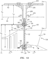
- FIG. 1A shows the addition of a first tie rod assembly 120 based upon the tie rod assembly of the '872 patent.
- the ID eyelet 128 and OD eyelet 130 respectively capture spheres or bearings 150 ( FIG. 1 ), 152 (also FIG. 2 ).
- the spheres are supported by shafts 154, 156.
- Exemplary shafts are separately formed from the bearings and pass through apertures in the bearings.
- Exemplary shafts are formed as bolts having heads 160, shanks 162, and distal threaded end portions 164 receiving nuts 166.
- the bolt shanks pass through arms of the respective ID and OD clevis 170, 172.
- the ID clevis 170 is mounted relative to engine static structure (e.g., snap engaged to a rear bearing hub 180).
- the exemplary OD clevis 172 extends to an OD end 190 ( FIG. 2 ).
- a threaded bore 192 extending inward from the OD end 190 receives the shank 194 of a tensioning bolt 196.
- the tensioning bolt is carried by a strut 200 extending radially inward from the outer case 62.
- the exemplary strut 200 is hollow with a centrally-apertured lower web 202 having an aperture passing the tensioning bolt shank 194.
- An OD surface of the web 202 surrounding the aperture (hole) compressively engages the underside of the tensioning bolt head to allow tension to be transmitted through the bolt.
- the strut 200 extends from an ID end 210 contacting or in close-facing spaced-apart relation to the clevis OD end 190 to an OD end 212 mounted to the outer case 62.
- An exemplary mounting is via a pair of mounting ears 220 ( FIG. 1A ) having threaded apertures receiving the shafts of mounting bolts 222 passing through the outer case 62.
- a hollow shank 204 of the strut 200 passes through an aperture in the inner case 64 and may be sealed to it via a seal structure 230 (e.g., a blade-type slider seal).
- FIG. 1A shows the OD bearing at a radial position R 2 and the ID bearing at a radial position R 1 .
- the effective length L 1 of the tie rod is R 2 -R 1 .
- the outer duct inner diameter (ID) surface is shown at a radius R 3 .
- the outer ring 140 outer diameter (OD) surface is shown at radius R 4 .
- a longer tie rod potentially involves problems as the engine encounters dynamic loads.
- a lengthened tie rod may be more subject to buckling.
- Geometric constraints may preclude making the tie rod more rigid and resistant to buckling. This is particularly relevant where an existing engine core configuration is applied to an application with larger radial span.
- L 2 the OD clevis 172 and the OD mounting portion (adjacent ears 220) of the strut will be relatively rigid leaving the strut hollow shank 204 to be optimized to provide desired compliance.
- exemplary L 2 is at least 30% of L 1 , more particularly, 30% to 200% or 40% to 100%.
- the radial span L 2 between the center of the OD spherical bearing and the clevis shank (or strut/clevis system) OD end may be at least 50% greater than a radial span L 3 (or R 2 -R 4 ) between an outer diameter (OD) surface of the outer ring 140 and the center of the OD spherical bearing. More particularly, exemplary L 2 may be 150% to 1000% of L 3 or 200% to 1000% or 300% to 800%.
- FIG. 1A first assembly 120 uses a relatively conventionally-dimensioned OD clevis 172 but adds a strut 200, other variations are possible.
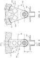
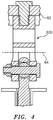
- FIGs. 3 and 4 show tie rod assembly 300 wherein, effectively, the OD clevis 320 is lengthened so as to engage the outer case 62 in a more conventional manner such as that of the '872 patent.
- the exemplary clevis shank 322 is shown with transverse apertures 324 reducing the spring constant to a desired tailored level.
- the revised situation may involve any of: a) modifying the baseline engine to outwardly shift a given case structure; b) modifying the baseline engine to add a different case structure outboard and shift from anchoring the OD end of the rod to said different case structure (e.g., shifting from 64 to 62 when 62 is added to an engine already having 64); or c) shifting from anchoring the OD end of the rod from one case structure of the baseline to a different case structure that is already in the baseline (e.g., shifting from 64 to 62 in an engine already having both).
- the strut may recapture compressive performance of the tie rod.
- other examples could change tie rod length such as by increasing it by only a portion of the added overall radial span change between mounting points from the baseline to the revised configuration.
- the strut reduces the required loads on the tie rod system.
- a lengthened rod would still need to handle the 1500 lb. (6.67 kN) tensile and 300 lb (1.33 kN). compressive load
- the strut allows these to be reduced to about 1300 lbs. (5.78 kN) and 260 lbs. (1.16 kN), respectively.
- the 260 lb. (1.16 kN) value is well within the buckling capability of the rod. In other cases, where this is not the case either a small amount of margin must be given up or a small further strengthening of the rod made if constraints allow.
- tie rod and clevis Conventional manufacturing materials and methods may be used for the tie rod and clevis.
- Typical tie rod and clevis materials are nickel-based superalloy (e.g., wrought and machined).
- the strut may be formed of similar materials and techniques.
- first, second, and the like in the following claims is for differentiation within the claim only and does not necessarily indicate relative or absolute importance or temporal order. Similarly, the identification in a claim of one element as “first” (or the like) does not preclude such "first” element from identifying an element that is referred to as “second” (or the like) in another claim or in the description.
Landscapes
- Engineering & Computer Science (AREA)
- Mechanical Engineering (AREA)
- General Engineering & Computer Science (AREA)
- Support Of The Bearing (AREA)
Abstract
Description
- The disclosure relates to gas turbine engines. More particularly, the disclosure relates to turbine section tie rods radially connecting inner diameter structure to outer diameter structure across one or more paths.
- United States Patent
4,979,872 (the '872 patent), of Myers et al., December 25, 1990, and entitled "Bearing compartment support", discloses tensioned tie rods connecting an inner diameter bearing compartment to an outer diameter structural case, spanning across a gaspath. The illustrated configuration has a circumferential array of hollow struts spanning the core flowpath between an inner ring and an outer ring. Outboard of the outer ring is a flowpath carrying bypass air from a fan or compressor for various cooling purposes. The tie rods pass radially through the hollow struts. Outer diameter (OD) ends of the tie rods form the eyelet portion of a spherical bearing system capturing the sphere (bearing) surface. The sphere is carried by a clevis extending radially outward. The outer diameter (OD) end of the clevis receives a tensioning bolt passing through the structural case. - One aspect of the disclosure involves a gas turbine engine turbine section comprising: an inner diameter structure; a turbine exhaust case surrounding the inner diameter structure and having an outer ring and an inner ring in concentric and radially spaced relationship and a plurality of circumferentially spaced hollow struts interconnecting and supporting said inner ring and said outer ring to each other; an outer casing surrounding said outer ring; and a plurality of tie rod assemblies interconnecting said inner diameter structure and said outer casing. Each of said tie rod assemblies comprises: a tie rod; at least a first clevis; and a tensioning bolt. The tie rod has: an inner diameter end; an outer diameter end; and an eyelet of an outer diameter spherical bearing formed at the outer diameter end. The first clevis carries a spherical ball between arms of said clevis, said spherical ball captured by the outer diameter spherical bearing eyelet, a shank of said clevis extending to an outer diameter (OD) end. The tensioning bolt is mated to a threaded opening formed in said clevis OD end whereby tightening said bolt applies a tension to said rod relative to the outer casing. A radial span between a center of the outer diameter spherical bearing and an inner diameter surface of the outer casing is at least 50% greater than a radial span between an outer diameter (OD) surface of the outer ring and the center of the spherical bearing.
- A further embodiment of any of the foregoing embodiments may additionally and/or alternatively include the tie rod assemblies further comprising: a plurality of struts, each strut respectively associated with an associated one of the tie rods. The strut extends radially between the clevis OD end and the outer casing to transmit the tension from the associated rod to the outer casing.
- A further embodiment of any of the foregoing embodiments may additionally and/or alternatively include each strut having a hollow body extending between an outer diameter end an inner diameter end. The inner diameter end has a web. The associated tensioning bolt extends through the web.
- A further embodiment of any of the foregoing embodiments may additionally and/or alternatively include each strut outer diameter end having one or more laterally outwardly protruding mounting projections; and one or more fasteners secure the one or more mounting projections to the outer casing.
- A further embodiment of any of the foregoing embodiments may additionally and/or alternatively include each strut being formed of a wrought nickel-based alloy.
- A further embodiment of any of the foregoing embodiments may additionally and/or alternatively include a radial span between a center of the outer diameter spherical bearing and the clevis shank OD end being at least 50% greater than a radial span between an outer diameter (OD) surface of the outer ring and the center of the spherical bearing.
- A further embodiment of any of the foregoing embodiments may additionally and/or alternatively include said radial span between the center of the spherical bearing and the clevis shank OD end being at least 100% greater than the radial span between the outer diameter (OD) surface of the outer ring and the center of the spherical bearing.
- A further embodiment of any of the foregoing embodiments may additionally and/or alternatively include the clevis shank comprising a plurality of transverse apertures.
- A further embodiment of any of the foregoing embodiments may additionally and/or alternatively include a spring rate of each tie rod assembly between the tie rod and the outer casing being greater than a spring rate of the associated tie rod.
- A further embodiment of any of the foregoing embodiments may additionally and/or alternatively include for each tie rod assembly: the tie rod having an inner diameter spherical bearing eyelet formed at the inner diameter end; and a second clevis being mounted to the inner diameter structure and carries a second spherical ball between arms of said second clevis, said second spherical ball captured by the inner diameter spherical bearing eyelet.
- A further embodiment of any of the foregoing embodiments may additionally and/or alternatively include for each tie rod assembly: a radial span between a center of the outer diameter spherical bearing and an inner diameter surface of the outer casing being 30% to 200% of a radial span between the center of the inner diameter spherical bearing and the center of the outer diameter spherical bearing.
- Another aspect of the disclosure involves a gas turbine engine turbine section comprising: an inner diameter structure; a turbine exhaust case surrounding the inner diameter structure and having an outer ring and an inner ring in concentric and radially spaced relationship and a plurality of circumferentially spaced hollow struts interconnecting and supporting said inner ring and said outer ring to each other; an outer casing surrounding said outer ring; and a plurality of tie rod assemblies interconnecting said inner diameter structure and said outer casing. Each of said tie rod assemblies comprising: a tie rod having: an inner diameter end; an outer diameter end; an eyelet of an inner diameter spherical bearing formed at the inner diameter end; and an eyelet of an outer diameter spherical bearing formed at the outer diameter end; an inner diameter clevis mounted to the inner diameter structure and carrying a first spherical ball between arms of said second clevis, said first spherical ball captured by the inner diameter spherical bearing eyelet; and an outer diameter clevis carrying a second spherical ball between arms of said outer diameter clevis, said second spherical ball captured by the outer diameter spherical bearing eyelet, a shank of said clevis extending to an outer diameter (OD) end; and a tensioning bolt mated to a threaded opening formed in said clevis OD end whereby tightening said bolt applies a tension to said rod relative to the outer casing. For each tie rod assembly: a radial span between a center of the outer diameter spherical bearing and an inner diameter surface of the outer casing is 30% to 200% of a radial span between the center of the inner diameter spherical bearing and the center of the outer diameter spherical bearing.
- A further embodiment of any of the foregoing embodiments may additionally and/or alternatively include for each tie rod assembly: the radial span between the center of the outer diameter spherical bearing and the inner diameter surface of the outer casing being 40% to 100% of the radial span between the center of the inner diameter spherical bearing and the center of the outer diameter spherical bearing.
- A further embodiment of any of the foregoing embodiments may additionally and/or alternatively include the tie rod assemblies each further comprising: a strut associated with the tie rod, wherein: the strut extends radially between the clevis OD end and the outer casing to transmit the tension from the associated rod to the outer casing.
- A further embodiment of any of the foregoing embodiments may additionally and/or alternatively include: each strut having a hollow body extending between an outer diameter end and an inner diameter end; the inner diameter end having a web; and the associated tensioning bolt extends through the web.
- A further embodiment of any of the foregoing embodiments may additionally and/or alternatively include: each strut outer diameter end having one or more laterally outwardly protruding mounting projections; and one or more fasteners securing the one or more mounting projections to the outer casing.
- A further embodiment of any of the foregoing embodiments may additionally and/or alternatively include each strut being formed of a wrought nickel-based alloy.
- Another aspect of the disclosure, which the Applicant expressly reserves the right to claim independently, involves a gas turbine engine turbine section comprising: an inner diameter structure; a turbine exhaust case surrounding the inner diameter structure and having an outer ring and an inner ring in concentric and radially spaced relationship and a plurality of circumferentially spaced hollow struts interconnecting and supporting said inner ring and said outer ring to each other; an outer casing surrounding said outer ring; a plurality of tie rod assemblies interconnecting said inner diameter structure and said outer casing. Each of said tie rod assemblies comprises: a tie rod having: an inner diameter end; an outer diameter end; and a spherical bearing eyelet formed at the outer diameter end; at least a first clevis carrying a spherical ball between arms of said clevis, said spherical ball captured by the spherical bearing eyelet, said first clevis comprising: a first shank having an outer diameter (OD) end; and a second shank having an outer diameter (OD) end; and a first bolt extending through an opening formed in said outer casing and mated to a threaded opening formed in said first shank OD end and a second bolt extending through an opening formed in said and mated to a threaded opening formed in said second shank OD end whereby tightening said first and second bolts applies a tension to said rod.
- A further embodiment of any of the foregoing embodiments may additionally and/or alternatively include each first clevis being formed of a wrought nickel-based alloy.
- A further embodiment of any of the foregoing embodiments may additionally and/or alternatively include the first and second shanks being at the same axial position along the engine.
- The details of one or more embodiments are set forth in the accompanying drawings and the description below. Other features, objects, and advantages will be apparent from the description and drawings, and from the claims.
-
-
FIG. 1 is a schematic central longitudinal sectional view of a gas turbine engine. -
FIG. 1A is an enlarged view of a turbine exhaust case area of the engine showing a tie rod assembly. -
FIG. 2 is a partial, partially schematic, transverse sectional view of the engine showing an outer diameter portion of the tie rod assembly. -
FIG. 3 is a transverse sectional view showing an alternate second tie rod assembly. -
FIG. 4 is a longitudinal sectional view of the second tie rod assembly along line 4-4 ofFIG. 3 . -
FIG. 5 is a transverse sectional view showing an alternate third tie rod assembly. - Like reference numbers and designations in the various drawings indicate like elements.
- Engine developments are placing increasing demands on tie rods. United States Patent
9,951,721 -
FIG. 1 shows a gas turbine engine 20 (having a centerline 500) based on the configuration of the '721 patent.FIG. 1A shows the addition of a firsttie rod assembly 120 based upon the tie rod assembly of the '872 patent. - The
assembly 120 includes arod 122 having an inner diameter end 124 and anouter diameter end 126. At the inner diameter end, aneyelet 128 is formed and, at theouter diameter end 126, aneyelet 130 is formed. Therod 122 has a main body orshank portion 132 passing through an associatedhollow strut 134 of theturbine exhaust case 136. The strut extends between an inner diameter (ID)ring 138 and an outer diameter (OD) ring 140 (alsoFIGs. 3 and 5 ). - The
ID eyelet 128 andOD eyelet 130 respectively capture spheres or bearings 150 (FIG. 1 ), 152 (alsoFIG. 2 ). The spheres are supported byshafts bolts having heads 160,shanks 162, and distal threadedend portions 164 receiving nuts 166. The bolt shanks pass through arms of the respective ID and ODclevis ID clevis 170 is mounted relative to engine static structure (e.g., snap engaged to a rear bearing hub 180). - The
exemplary OD clevis 172 extends to an OD end 190 (FIG. 2 ). A threadedbore 192 extending inward from theOD end 190 receives theshank 194 of atensioning bolt 196. The tensioning bolt is carried by astrut 200 extending radially inward from theouter case 62. Theexemplary strut 200 is hollow with a centrally-aperturedlower web 202 having an aperture passing thetensioning bolt shank 194. An OD surface of theweb 202 surrounding the aperture (hole) compressively engages the underside of the tensioning bolt head to allow tension to be transmitted through the bolt. - The
strut 200 extends from anID end 210 contacting or in close-facing spaced-apart relation to the clevis OD end 190 to anOD end 212 mounted to theouter case 62. An exemplary mounting is via a pair of mounting ears 220 (FIG. 1A ) having threaded apertures receiving the shafts of mountingbolts 222 passing through theouter case 62. Ahollow shank 204 of thestrut 200 passes through an aperture in theinner case 64 and may be sealed to it via a seal structure 230 (e.g., a blade-type slider seal). -
FIG. 1A shows the OD bearing at a radial position R2 and the ID bearing at a radial position R1. The effective length L1 of the tie rod is R2-R1. The outer duct inner diameter (ID) surface is shown at a radius R3. Theouter ring 140 outer diameter (OD) surface is shown at radius R4. - Use of the
strut 200 allows R2 (and thus L1) to be limited. - A longer tie rod (e.g., where the OD bearing was near the outer case) potentially involves problems as the engine encounters dynamic loads. For example, a lengthened tie rod may be more subject to buckling. Geometric constraints may preclude making the tie rod more rigid and resistant to buckling. This is particularly relevant where an existing engine core configuration is applied to an application with larger radial span. By tailoring the relative length of the
tie rod 122 and strut 200, as well as their relative tensile properties (e.g., spring constant (via geometry and material elastic modulus)) one can apportion the relative pre-tensioning strains on thestrut 200 and the tie rod. This can avoid failures under dynamic loads. For example, as discussed below, compressive buckling may be avoided. - The ability to tailor the tie rod to the strut (or strut/clevis system) will depend on the available length or radial span of the strut/clevis system. This length is shown as L2 in
FIG. 1A . Some portion of this length will be unusable due to mounting considerations. For example, in theFIG. 1A embodiment, theOD clevis 172 and the OD mounting portion (adjacent ears 220) of the strut will be relatively rigid leaving the struthollow shank 204 to be optimized to provide desired compliance. To provide sufficient radial span for optimizing the strut/OD clevis system, exemplary L2 is at least 30% of L1, more particularly, 30% to 200% or 40% to 100%. - An alternative measurement reflects the tie rod protruding from the
OD ring 140. In such a case, the radial span L2 between the center of the OD spherical bearing and the clevis shank (or strut/clevis system) OD end may be at least 50% greater than a radial span L3 (or R2-R4) between an outer diameter (OD) surface of theouter ring 140 and the center of the OD spherical bearing. More particularly, exemplary L2 may be 150% to 1000% of L3 or 200% to 1000% or 300% to 800%. - Whereas the
FIG. 1A first assembly 120 uses a relatively conventionally-dimensionedOD clevis 172 but adds astrut 200, other variations are possible. -
FIGs. 3 and4 showtie rod assembly 300 wherein, effectively, theOD clevis 320 is lengthened so as to engage theouter case 62 in a more conventional manner such as that of the '872 patent. Theexemplary clevis shank 322 is shown withtransverse apertures 324 reducing the spring constant to a desired tailored level. - Although no separate strut is involved, the increased clevis length can allow optimization of the clevis compliance in a portion of the clevis between the clevis arms and the threaded bore. For this embodiment, the analogous length to L2 alternatively be measured from the clevis's bearing center to its OD end or via the R3-R2 number used for the first embodiment. This length may have a similar relationship to the tie rod length as that of the first embodiment.
-
FIG. 5 shows an alternative thirdtie rod assembly 400 otherwise similar to the secondtie rod assembly 300 but wherein theOD clevis 420 has twoshanks - Tables I and II below illustrate an example where a baseline rod length L1 is ten inches (254 mm). A hypothetical revised rod length is fifteen inches (381 mm). For example, the revised situation may involve any of: a) modifying the baseline engine to outwardly shift a given case structure; b) modifying the baseline engine to add a different case structure outboard and shift from anchoring the OD end of the rod to said different case structure (e.g., shifting from 64 to 62 when 62 is added to an engine already having 64); or c) shifting from anchoring the OD end of the rod from one case structure of the baseline to a different case structure that is already in the baseline (e.g., shifting from 64 to 62 in an engine already having both).
- From Table I, if all other factors are held constant, the length increase from ten to fifteen inches (from 254 mm to 381 mm) reduces the threshold buckling compressive load from the baseline of over 550 lbs. (2.45 kN) to about 250 lbs (1.11 kN). The latter is below the target compressive load and thus the rod will likely buckle in service. Although compressive performance could be increased by increasing rod diameter, packaging or other constraints may preclude this.
- From Table II, it is seen how use of the strut may recapture compressive performance of the tie rod. Although the example preserves Tie rod length, other examples could change tie rod length such as by increasing it by only a portion of the added overall radial span change between mounting points from the baseline to the revised configuration. To accommodate a given deflection, the strut reduces the required loads on the tie rod system. Thus, whereas a lengthened rod would still need to handle the 1500 lb. (6.67 kN) tensile and 300 lb (1.33 kN). compressive load, the strut allows these to be reduced to about 1300 lbs. (5.78 kN) and 260 lbs. (1.16 kN), respectively. In the particular example, the 260 lb. (1.16 kN) value is well within the buckling capability of the rod. In other cases, where this is not the case either a small amount of margin must be given up or a small further strengthening of the rod made if constraints allow.
- In the following tables the following conversions apply:
- 1 In. = 25.4 mm
- 1 Lbs. = 4.45 N
- 1 Mpsi = 6.89 GPa
- 1 psi = 6.89 kPa
- 1 in. = 2.54 mm
- 1 in.2 = 645 mm2
- 1 in.4 = 416231 mm4
- 1 Lbs./in. = 5.71 N/mm
- Conventional manufacturing materials and methods may be used for the tie rod and clevis. Typical tie rod and clevis materials are nickel-based superalloy (e.g., wrought and machined). The strut may be formed of similar materials and techniques.
- The use of "first", "second", and the like in the following claims is for differentiation within the claim only and does not necessarily indicate relative or absolute importance or temporal order. Similarly, the identification in a claim of one element as "first" (or the like) does not preclude such "first" element from identifying an element that is referred to as "second" (or the like) in another claim or in the description.
- One or more embodiments have been described. Nevertheless, it will be understood that various modifications may be made. For example, when applied to an existing baseline configuration, details of such baseline may influence details of particular implementations. Accordingly, other embodiments are within the scope of the following claims.
| Desc. | Sym | Value | Value | Units | Formula | Comment | |
| Length of the rod | L or L1 | 10 | 15 | In. | - | ||
| Target tensile force through rod | PT | 1500 | 1500 | Lbs. | - | ||
| Target compression force through | P | C | 300 | 300 | Lbs. | - | |
| Modulus of elasticity | E | 30.0 | 30.0 | Mpsi | - | Exemplary material | |
| Yield capability of material | Sy | 40,000 | 40,000 | psi | - | Exemplary material | |
| Max rod diameter | d | 0.25 | 0.25 | in. | - | ||
| Rod cross-sectional area | A | 0.049 | 0.049 | in.2 |  | ||
| Area moment of inertia | I | 0.0002 | 0.0002 | in.4 |  | ||
| Buckling capability of the rod | Pcr | 567.7 | 252.33 | Lbs. |  | Assumes pin rod ends required for thermal compliance c=1 | |
| Tensile Stress in rod | σ | 30557.74 | 30557.74 | psi | P / A |
| Long Rod | Short Rod + Strut | |||||
| Desc. | Symbol | Formula | Units | Value | Value | Comment |
| Rod Length | L or L1 | - | in. | 15 | 10 | |
| Rod Cross Sectional Area | A | - | in.2 | 0.049 | ||
| Modulus of Elasticity | E | - | Mpsi | 30.0 | ||
| Rod Stiffness | KRod |  | Lbs. / in. | 98,174 | 147,262 | Shorter rod is stiffer |
| Strut Stiffness | KStrut | - | Lbs. / in. | N/A | 160,000 | |
| Rest of System Stiffness | KOther | - | Lbs. / in. | 90,000 | 90,000 | |
| Total System Stiffness | KSystem |  | Lbs. / in. | 46,954 | 38,116.94 | |
| Tensile Load | P | ksystemx | Lbs. | 1500 | 1322.7 | Given for Long Rod, calculated for Short Rod + Strut |
| Tensile Deflection | x | P/ kSystem | in. | 0.032 | 0.032 | Calculated for Long Rod, Given for Short Rod + Strut |
| Compressive Load | P | ksystemx | Lbs. | 300 | 264.5 | Given for Long Rod, calculated for Short Rod + Strut |
| Compressive Deflection | x | P/kSystem | in. | 0.006 | 0.006 | Calculated for Long Rod, Given for Short Rod + Strut |
Claims (14)
- A gas turbine engine turbine section comprising:an inner diameter structure;a turbine exhaust case (136) surrounding the inner diameter structure and having an outer ring (140) and an inner ring (138) in concentric and radially spaced relationship and a plurality of circumferentially spaced hollow struts (136) interconnecting and supporting said inner ring (138) and said outer ring (140) to each other;an outer casing (62) surrounding said outer ring (140); anda plurality of tie rod assemblies (120; 300; 400) interconnecting said inner diameter structure and said outer casing (62), each of said tie rod assemblies (120; 300; 400) comprising:
a tie rod (122) having:an inner diameter end (124);an outer diameter end (126); andan eyelet (130) of an outer diameter spherical bearing formed at the outer diameter end (126); andat least a first clevis (172; 320; 420) carrying a spherical ball (152) between arms of said clevis (172; 320; 420), said spherical ball (152) captured by the outer diameter spherical bearing eyelet (130), a shank (194; 322; 422A, 422B) of said clevis (172; 320; 420) extending to an outer diameter (OD) end (190) of said clevis (172; 320; 420); anda tensioning bolt (196) mated to a threaded opening (192) formed in said clevis OD end (190) whereby tightening said bolt (196) applies a tension to said tie rod (122) relative to the outer casing (62),
wherein:
a radial span (L2) between a center of the outer diameter spherical bearing and an inner diameter surface of the outer casing (62) is at least 50% greater than a radial span (L3) between an outer diameter (OD) surface of the outer ring (140) and the center of the spherical bearing. - The gas turbine engine turbine section of claim 1, wherein a radial span (L2) between a center of the outer diameter spherical bearing and the clevis shank OD end (190) is at least 50% greater than the radial span (L3) between the outer diameter (OD) surface of the outer ring (140) and the center of the spherical bearing.
- The gas turbine engine turbine section of claim 1 or 2, wherein said radial span between the center of the outer diameter spherical bearing and the clevis shank OD end (190) is at least 100% greater than the radial span (L3) between the outer diameter (OD) surface of the outer ring (140) and the center of the spherical bearing.
- The gas turbine engine turbine section of any preceding claim, wherein the clevis shank (194; 322; 422A, 422B) comprises a plurality of transverse apertures.
- The gas turbine engine turbine section of any preceding claim, wherein a spring rate of each tie rod assembly (120; 300; 400) between the tie rod (122) and the outer casing (62) is greater than a spring rate of the associated tie rod (122).
- The gas turbine engine turbine section of any preceding claim, wherein for each tie rod assembly (120; 300; 400):the tie rod (122) has an inner diameter spherical bearing eyelet (128) formed at the inner diameter end (124); anda second clevis (170) is mounted to the inner diameter structure and carries a second spherical ball (150) between arms of said second clevis (170), said second spherical ball (150) captured by the inner diameter spherical bearing eyelet (128) .
- The gas turbine engine turbine section of claim 6, wherein for each tie rod assembly (120; 300; 400):
the radial span (L2) between the center of the outer diameter spherical bearing and the inner diameter surface of the outer casing (62) is 30% to 200% of a radial span (L1) between the center of the inner diameter spherical bearing and the center of the outer diameter spherical bearing. - The gas turbine engine turbine section of any preceding claim, the tie rod assemblies (120) further comprising:
a plurality of struts (200), each strut (200) respectively associated with an associated one of the tie rods (122), wherein:
the strut (200) extends radially between the clevis OD end (190) and the outer casing (62) to transmit the tension from the associated tie rod (122) to the outer casing (62). - A gas turbine engine turbine section comprising:an inner diameter structure;a turbine exhaust case (136) surrounding the inner diameter structure and having an outer ring (140) and an inner ring (138) in concentric and radially spaced relationship and a plurality of circumferentially spaced hollow struts (136) interconnecting and supporting said inner ring (138) and said outer ring (140) to each other;an outer casing (62) surrounding said outer ring (140); anda plurality of tie rod assemblies (120; 300; 400) interconnecting said inner diameter structure and said outer casing (62), each of said tie rod assemblies (120; 300; 400) comprising:a tie rod (122)having:an inner diameter end (124);an outer diameter end (126);an eyelet (128) of an inner diameter spherical bearing formed at the inner diameter end (124); andan eyelet (130) of an outer diameter spherical bearing formed at the outer diameter end (126);an inner diameter clevis (170) mounted to the inner diameter structure and carrying a first spherical ball (150) between arms of said inner diameter clevis (170), said first spherical ball (150) captured by the inner diameter spherical bearing eyelet (128); andan outer diameter clevis (172; 320; 420) carrying a second spherical ball (152) between arms of said outer diameter clevis (172; 320; 420), said second spherical ball (152) captured by the outer diameter spherical bearing eyelet (130), a shank (194; 322; 422A, 422B) of said clevis (172; 320; 420) extending to an outer diameter (OD) end (190); anda tensioning bolt (196) mated to a threaded opening (192) formed in said clevis OD end (190) whereby tightening said bolt (196) applies a tension to said tie rod (122) relative to the outer casing (62),wherein for each tie rod assembly (120; 300; 400):
a radial (L2) span between a center of the outer diameter spherical bearing and an inner diameter surface of the outer casing (62) is 30% to 200% of a radial span (L1) between the center of the inner diameter spherical bearing and the center of the outer diameter spherical bearing. - The gas turbine engine turbine section of claim 9, wherein for each tie rod assembly (120; 300; 400):
the radial span (L2) between the center of the outer diameter spherical bearing and the inner diameter surface of the outer casing (62) is 40% to 100% of the radial span (L1) between the center of the inner diameter spherical bearing and the center of the outer diameter spherical bearing. - The gas turbine engine turbine section of claim 9 or 10, the tie rod assemblies (120; 300; 400) each further comprising:
a strut (200) respectively associated with the associated tie rod (122), wherein:
the strut (200) extends radially between the clevis OD end (190) and the outer casing (62) to transmit the tension from the associated tie rod (122) to the outer casing (62). - The gas turbine engine turbine section of claim 8 or 11, wherein:each strut (200) has a hollow body (204) extending between an outer diameter end (212) and an inner diameter end (210) ;the inner diameter end (210) has a web (202); andthe associated tensioning bolt (196) extends through the web (202).
- The gas turbine engine turbine section of claim 12, wherein:each strut outer diameter end (212) has one or more laterally outwardly protruding mounting projections (220); andone or more fasteners (222)secure the one or more mounting projections (220)to the outer casing (62).
- The gas turbine engine turbine section of any of claims 8, 11, 12 or 13, wherein each strut (200) is formed of a wrought nickel-based alloy.
Applications Claiming Priority (1)
| Application Number | Priority Date | Filing Date | Title |
|---|---|---|---|
| US16/270,102 US10823011B2 (en) | 2019-02-07 | 2019-02-07 | Turbine engine tie rod systems |
Publications (2)
| Publication Number | Publication Date |
|---|---|
| EP3693562A1 true EP3693562A1 (en) | 2020-08-12 |
| EP3693562B1 EP3693562B1 (en) | 2023-04-19 |
Family
ID=68808076
Family Applications (1)
| Application Number | Title | Priority Date | Filing Date |
|---|---|---|---|
| EP19213970.7A Active EP3693562B1 (en) | 2019-02-07 | 2019-12-05 | Turbine engine tie rod systems |
Country Status (2)
| Country | Link |
|---|---|
| US (1) | US10823011B2 (en) |
| EP (1) | EP3693562B1 (en) |
Citations (6)
| Publication number | Priority date | Publication date | Assignee | Title |
|---|---|---|---|---|
| US4979872A (en) | 1989-06-22 | 1990-12-25 | United Technologies Corporation | Bearing compartment support |
| EP1655457A1 (en) * | 2004-10-29 | 2006-05-10 | General Electric Company | Gas turbine engine and method of assembling same |
| GB2490781A (en) * | 2011-05-09 | 2012-11-14 | Snecma | Suspension rod for a turbojet with eccentric ball joint |
| DE102011077502A1 (en) * | 2011-06-14 | 2012-12-20 | Rolls-Royce Deutschland Ltd & Co Kg | Device for connecting inner wall and outer wall of bypass filter channel of turbojet engine unit, has two wall-like supporting elements, which are partially arranged in assembled state in direction of fluid flow in bypass filter channel |
| US9784129B2 (en) * | 2014-08-01 | 2017-10-10 | Pratt & Whitney Canada Corp. | Rear mount assembly for gas turbine engine |
| US9951721B2 (en) | 2014-10-21 | 2018-04-24 | United Technologies Corporation | Three-stream gas turbine engine architecture |
Family Cites Families (6)
| Publication number | Priority date | Publication date | Assignee | Title |
|---|---|---|---|---|
| US5076049A (en) * | 1990-04-02 | 1991-12-31 | General Electric Company | Pretensioned frame |
| DE59007880D1 (en) | 1990-12-10 | 1995-01-12 | Asea Brown Boveri | Storage of a thermal turbo machine. |
| US5160251A (en) * | 1991-05-13 | 1992-11-03 | General Electric Company | Lightweight engine turbine bearing support assembly for withstanding radial and axial loads |
| US5385015A (en) * | 1993-07-02 | 1995-01-31 | United Technologies Corporation | Augmentor burner |
| US9200536B2 (en) | 2011-10-17 | 2015-12-01 | United Technologies Corporation | Mid turbine frame (MTF) for a gas turbine engine |
| EP2946083B1 (en) | 2013-01-21 | 2023-07-19 | Raytheon Technologies Corporation | Turbine case adjustment using adjustable tie rods |
-
2019
- 2019-02-07 US US16/270,102 patent/US10823011B2/en active Active
- 2019-12-05 EP EP19213970.7A patent/EP3693562B1/en active Active
Patent Citations (6)
| Publication number | Priority date | Publication date | Assignee | Title |
|---|---|---|---|---|
| US4979872A (en) | 1989-06-22 | 1990-12-25 | United Technologies Corporation | Bearing compartment support |
| EP1655457A1 (en) * | 2004-10-29 | 2006-05-10 | General Electric Company | Gas turbine engine and method of assembling same |
| GB2490781A (en) * | 2011-05-09 | 2012-11-14 | Snecma | Suspension rod for a turbojet with eccentric ball joint |
| DE102011077502A1 (en) * | 2011-06-14 | 2012-12-20 | Rolls-Royce Deutschland Ltd & Co Kg | Device for connecting inner wall and outer wall of bypass filter channel of turbojet engine unit, has two wall-like supporting elements, which are partially arranged in assembled state in direction of fluid flow in bypass filter channel |
| US9784129B2 (en) * | 2014-08-01 | 2017-10-10 | Pratt & Whitney Canada Corp. | Rear mount assembly for gas turbine engine |
| US9951721B2 (en) | 2014-10-21 | 2018-04-24 | United Technologies Corporation | Three-stream gas turbine engine architecture |
Also Published As
| Publication number | Publication date |
|---|---|
| EP3693562B1 (en) | 2023-04-19 |
| US20200256216A1 (en) | 2020-08-13 |
| US10823011B2 (en) | 2020-11-03 |
Similar Documents
| Publication | Publication Date | Title |
|---|---|---|
| US8118251B2 (en) | Mounting system for a gas turbine engine | |
| EP2584152B1 (en) | Mid turbine frame (MTF) for a gas turbine engine | |
| EP2103516B1 (en) | Mounting system for a gas turbine engine | |
| US4979872A (en) | Bearing compartment support | |
| US9896966B2 (en) | Tie rod for a gas turbine engine | |
| US4944151A (en) | Segmented combustor panel | |
| US8215901B2 (en) | Gas turbine engines and related systems involving offset turbine frame struts | |
| US6443698B1 (en) | Method and apparatus for centering rotor assembly damper bearings | |
| US20050271505A1 (en) | Turbine engine shroud segment, hanger and assembly | |
| EP0805108A2 (en) | Aircraft engine thrust mount | |
| US8757579B2 (en) | Linking device for linking a first body to a second body, in particular for an aircraft engine assembly | |
| US20040062639A1 (en) | Turbine engine shroud assembly including axially floating shroud segment | |
| US20170260908A1 (en) | One degree-of-constraint semi-fusible gearbox mounting link | |
| US8051662B2 (en) | Transition duct assemblies and gas turbine engine systems involving such assemblies | |
| CN101999046A (en) | Fixed elements and exhaust gas turbocharger with variable turbine geometry | |
| US11898682B2 (en) | System for spacing and fastening tubular structures | |
| WO2007018627A1 (en) | Radially expanding turbine engine exhaust cylinder interface | |
| EP3693562A1 (en) | Turbine engine tie rod systems | |
| US10184511B2 (en) | Linkage with spherical or journal bearing assembly | |
| CN111703581B (en) | Aircraft rear engine fastener and aircraft | |
| EP0997653A2 (en) | Redundant clevis pin pair | |
| JPS60500762A (en) | laminated tubular links | |
| US20060120652A1 (en) | Roller bearing with cage fastener | |
| DE602005004005T2 (en) | Thrust bearing arrangement for gas turbines | |
| US20130042629A1 (en) | Turbomachine load management assembly |
Legal Events
| Date | Code | Title | Description |
|---|---|---|---|
| PUAI | Public reference made under article 153(3) epc to a published international application that has entered the european phase |
Free format text: ORIGINAL CODE: 0009012 |
|
| STAA | Information on the status of an ep patent application or granted ep patent |
Free format text: STATUS: THE APPLICATION HAS BEEN PUBLISHED |
|
| AK | Designated contracting states |
Kind code of ref document: A1 Designated state(s): AL AT BE BG CH CY CZ DE DK EE ES FI FR GB GR HR HU IE IS IT LI LT LU LV MC MK MT NL NO PL PT RO RS SE SI SK SM TR |
|
| AX | Request for extension of the european patent |
Extension state: BA ME |
|
| STAA | Information on the status of an ep patent application or granted ep patent |
Free format text: STATUS: REQUEST FOR EXAMINATION WAS MADE |
|
| 17P | Request for examination filed |
Effective date: 20210211 |
|
| RAP1 | Party data changed (applicant data changed or rights of an application transferred) |
Owner name: RAYTHEON TECHNOLOGIES CORPORATION |
|
| RBV | Designated contracting states (corrected) |
Designated state(s): AL AT BE BG CH CY CZ DE DK EE ES FI FR GB GR HR HU IE IS IT LI LT LU LV MC MK MT NL NO PL PT RO RS SE SI SK SM TR |
|
| GRAP | Despatch of communication of intention to grant a patent |
Free format text: ORIGINAL CODE: EPIDOSNIGR1 |
|
| STAA | Information on the status of an ep patent application or granted ep patent |
Free format text: STATUS: GRANT OF PATENT IS INTENDED |
|
| INTG | Intention to grant announced |
Effective date: 20221103 |
|
| GRAS | Grant fee paid |
Free format text: ORIGINAL CODE: EPIDOSNIGR3 |
|
| GRAA | (expected) grant |
Free format text: ORIGINAL CODE: 0009210 |
|
| STAA | Information on the status of an ep patent application or granted ep patent |
Free format text: STATUS: THE PATENT HAS BEEN GRANTED |
|
| AK | Designated contracting states |
Kind code of ref document: B1 Designated state(s): AL AT BE BG CH CY CZ DE DK EE ES FI FR GB GR HR HU IE IS IT LI LT LU LV MC MK MT NL NO PL PT RO RS SE SI SK SM TR |
|
| REG | Reference to a national code |
Ref country code: GB Ref legal event code: FG4D |
|
| REG | Reference to a national code |
Ref country code: CH Ref legal event code: EP |
|
| REG | Reference to a national code |
Ref country code: DE Ref legal event code: R096 Ref document number: 602019027693 Country of ref document: DE |
|
| REG | Reference to a national code |
Ref country code: IE Ref legal event code: FG4D |
|
| REG | Reference to a national code |
Ref country code: AT Ref legal event code: REF Ref document number: 1561317 Country of ref document: AT Kind code of ref document: T Effective date: 20230515 |
|
| P01 | Opt-out of the competence of the unified patent court (upc) registered |
Effective date: 20230521 |
|
| REG | Reference to a national code |
Ref country code: LT Ref legal event code: MG9D |
|
| REG | Reference to a national code |
Ref country code: NL Ref legal event code: MP Effective date: 20230419 |
|
| REG | Reference to a national code |
Ref country code: AT Ref legal event code: MK05 Ref document number: 1561317 Country of ref document: AT Kind code of ref document: T Effective date: 20230419 |
|
| PG25 | Lapsed in a contracting state [announced via postgrant information from national office to epo] |
Ref country code: NL Free format text: LAPSE BECAUSE OF FAILURE TO SUBMIT A TRANSLATION OF THE DESCRIPTION OR TO PAY THE FEE WITHIN THE PRESCRIBED TIME-LIMIT Effective date: 20230419 |
|
| PG25 | Lapsed in a contracting state [announced via postgrant information from national office to epo] |
Ref country code: SE Free format text: LAPSE BECAUSE OF FAILURE TO SUBMIT A TRANSLATION OF THE DESCRIPTION OR TO PAY THE FEE WITHIN THE PRESCRIBED TIME-LIMIT Effective date: 20230419 Ref country code: PT Free format text: LAPSE BECAUSE OF FAILURE TO SUBMIT A TRANSLATION OF THE DESCRIPTION OR TO PAY THE FEE WITHIN THE PRESCRIBED TIME-LIMIT Effective date: 20230821 Ref country code: NO Free format text: LAPSE BECAUSE OF FAILURE TO SUBMIT A TRANSLATION OF THE DESCRIPTION OR TO PAY THE FEE WITHIN THE PRESCRIBED TIME-LIMIT Effective date: 20230719 Ref country code: ES Free format text: LAPSE BECAUSE OF FAILURE TO SUBMIT A TRANSLATION OF THE DESCRIPTION OR TO PAY THE FEE WITHIN THE PRESCRIBED TIME-LIMIT Effective date: 20230419 Ref country code: AT Free format text: LAPSE BECAUSE OF FAILURE TO SUBMIT A TRANSLATION OF THE DESCRIPTION OR TO PAY THE FEE WITHIN THE PRESCRIBED TIME-LIMIT Effective date: 20230419 |
|
| RAP4 | Party data changed (patent owner data changed or rights of a patent transferred) |
Owner name: RTX CORPORATION |
|
| PG25 | Lapsed in a contracting state [announced via postgrant information from national office to epo] |
Ref country code: RS Free format text: LAPSE BECAUSE OF FAILURE TO SUBMIT A TRANSLATION OF THE DESCRIPTION OR TO PAY THE FEE WITHIN THE PRESCRIBED TIME-LIMIT Effective date: 20230419 Ref country code: PL Free format text: LAPSE BECAUSE OF FAILURE TO SUBMIT A TRANSLATION OF THE DESCRIPTION OR TO PAY THE FEE WITHIN THE PRESCRIBED TIME-LIMIT Effective date: 20230419 Ref country code: LV Free format text: LAPSE BECAUSE OF FAILURE TO SUBMIT A TRANSLATION OF THE DESCRIPTION OR TO PAY THE FEE WITHIN THE PRESCRIBED TIME-LIMIT Effective date: 20230419 Ref country code: LT Free format text: LAPSE BECAUSE OF FAILURE TO SUBMIT A TRANSLATION OF THE DESCRIPTION OR TO PAY THE FEE WITHIN THE PRESCRIBED TIME-LIMIT Effective date: 20230419 Ref country code: IS Free format text: LAPSE BECAUSE OF FAILURE TO SUBMIT A TRANSLATION OF THE DESCRIPTION OR TO PAY THE FEE WITHIN THE PRESCRIBED TIME-LIMIT Effective date: 20230819 Ref country code: HR Free format text: LAPSE BECAUSE OF FAILURE TO SUBMIT A TRANSLATION OF THE DESCRIPTION OR TO PAY THE FEE WITHIN THE PRESCRIBED TIME-LIMIT Effective date: 20230419 Ref country code: GR Free format text: LAPSE BECAUSE OF FAILURE TO SUBMIT A TRANSLATION OF THE DESCRIPTION OR TO PAY THE FEE WITHIN THE PRESCRIBED TIME-LIMIT Effective date: 20230720 Ref country code: AL Free format text: LAPSE BECAUSE OF FAILURE TO SUBMIT A TRANSLATION OF THE DESCRIPTION OR TO PAY THE FEE WITHIN THE PRESCRIBED TIME-LIMIT Effective date: 20230419 |
|
| PG25 | Lapsed in a contracting state [announced via postgrant information from national office to epo] |
Ref country code: FI Free format text: LAPSE BECAUSE OF FAILURE TO SUBMIT A TRANSLATION OF THE DESCRIPTION OR TO PAY THE FEE WITHIN THE PRESCRIBED TIME-LIMIT Effective date: 20230419 |
|
| PG25 | Lapsed in a contracting state [announced via postgrant information from national office to epo] |
Ref country code: SK Free format text: LAPSE BECAUSE OF FAILURE TO SUBMIT A TRANSLATION OF THE DESCRIPTION OR TO PAY THE FEE WITHIN THE PRESCRIBED TIME-LIMIT Effective date: 20230419 |
|
| REG | Reference to a national code |
Ref country code: DE Ref legal event code: R097 Ref document number: 602019027693 Country of ref document: DE |
|
| PG25 | Lapsed in a contracting state [announced via postgrant information from national office to epo] |
Ref country code: SM Free format text: LAPSE BECAUSE OF FAILURE TO SUBMIT A TRANSLATION OF THE DESCRIPTION OR TO PAY THE FEE WITHIN THE PRESCRIBED TIME-LIMIT Effective date: 20230419 Ref country code: SK Free format text: LAPSE BECAUSE OF FAILURE TO SUBMIT A TRANSLATION OF THE DESCRIPTION OR TO PAY THE FEE WITHIN THE PRESCRIBED TIME-LIMIT Effective date: 20230419 Ref country code: RO Free format text: LAPSE BECAUSE OF FAILURE TO SUBMIT A TRANSLATION OF THE DESCRIPTION OR TO PAY THE FEE WITHIN THE PRESCRIBED TIME-LIMIT Effective date: 20230419 Ref country code: EE Free format text: LAPSE BECAUSE OF FAILURE TO SUBMIT A TRANSLATION OF THE DESCRIPTION OR TO PAY THE FEE WITHIN THE PRESCRIBED TIME-LIMIT Effective date: 20230419 Ref country code: DK Free format text: LAPSE BECAUSE OF FAILURE TO SUBMIT A TRANSLATION OF THE DESCRIPTION OR TO PAY THE FEE WITHIN THE PRESCRIBED TIME-LIMIT Effective date: 20230419 Ref country code: CZ Free format text: LAPSE BECAUSE OF FAILURE TO SUBMIT A TRANSLATION OF THE DESCRIPTION OR TO PAY THE FEE WITHIN THE PRESCRIBED TIME-LIMIT Effective date: 20230419 |
|
| PLBE | No opposition filed within time limit |
Free format text: ORIGINAL CODE: 0009261 |
|
| STAA | Information on the status of an ep patent application or granted ep patent |
Free format text: STATUS: NO OPPOSITION FILED WITHIN TIME LIMIT |
|
| 26N | No opposition filed |
Effective date: 20240122 |
|
| PG25 | Lapsed in a contracting state [announced via postgrant information from national office to epo] |
Ref country code: SI Free format text: LAPSE BECAUSE OF FAILURE TO SUBMIT A TRANSLATION OF THE DESCRIPTION OR TO PAY THE FEE WITHIN THE PRESCRIBED TIME-LIMIT Effective date: 20230419 |
|
| PG25 | Lapsed in a contracting state [announced via postgrant information from national office to epo] |
Ref country code: SI Free format text: LAPSE BECAUSE OF FAILURE TO SUBMIT A TRANSLATION OF THE DESCRIPTION OR TO PAY THE FEE WITHIN THE PRESCRIBED TIME-LIMIT Effective date: 20230419 Ref country code: IT Free format text: LAPSE BECAUSE OF FAILURE TO SUBMIT A TRANSLATION OF THE DESCRIPTION OR TO PAY THE FEE WITHIN THE PRESCRIBED TIME-LIMIT Effective date: 20230419 |
|
| REG | Reference to a national code |
Ref country code: CH Ref legal event code: PL |
|
| PG25 | Lapsed in a contracting state [announced via postgrant information from national office to epo] |
Ref country code: LU Free format text: LAPSE BECAUSE OF NON-PAYMENT OF DUE FEES Effective date: 20231205 |
|
| PG25 | Lapsed in a contracting state [announced via postgrant information from national office to epo] |
Ref country code: MC Free format text: LAPSE BECAUSE OF FAILURE TO SUBMIT A TRANSLATION OF THE DESCRIPTION OR TO PAY THE FEE WITHIN THE PRESCRIBED TIME-LIMIT Effective date: 20230419 |
|
| REG | Reference to a national code |
Ref country code: BE Ref legal event code: MM Effective date: 20231231 |
|
| PG25 | Lapsed in a contracting state [announced via postgrant information from national office to epo] |
Ref country code: MC Free format text: LAPSE BECAUSE OF FAILURE TO SUBMIT A TRANSLATION OF THE DESCRIPTION OR TO PAY THE FEE WITHIN THE PRESCRIBED TIME-LIMIT Effective date: 20230419 Ref country code: LU Free format text: LAPSE BECAUSE OF NON-PAYMENT OF DUE FEES Effective date: 20231205 |
|
| REG | Reference to a national code |
Ref country code: IE Ref legal event code: MM4A |
|
| PG25 | Lapsed in a contracting state [announced via postgrant information from national office to epo] |
Ref country code: IE Free format text: LAPSE BECAUSE OF NON-PAYMENT OF DUE FEES Effective date: 20231205 |
|
| PG25 | Lapsed in a contracting state [announced via postgrant information from national office to epo] |
Ref country code: BE Free format text: LAPSE BECAUSE OF NON-PAYMENT OF DUE FEES Effective date: 20231231 |
|
| PG25 | Lapsed in a contracting state [announced via postgrant information from national office to epo] |
Ref country code: CH Free format text: LAPSE BECAUSE OF NON-PAYMENT OF DUE FEES Effective date: 20231231 |
|
| PG25 | Lapsed in a contracting state [announced via postgrant information from national office to epo] |
Ref country code: IE Free format text: LAPSE BECAUSE OF NON-PAYMENT OF DUE FEES Effective date: 20231205 Ref country code: CH Free format text: LAPSE BECAUSE OF NON-PAYMENT OF DUE FEES Effective date: 20231231 Ref country code: BE Free format text: LAPSE BECAUSE OF NON-PAYMENT OF DUE FEES Effective date: 20231231 |
|
| PG25 | Lapsed in a contracting state [announced via postgrant information from national office to epo] |
Ref country code: BG Free format text: LAPSE BECAUSE OF FAILURE TO SUBMIT A TRANSLATION OF THE DESCRIPTION OR TO PAY THE FEE WITHIN THE PRESCRIBED TIME-LIMIT Effective date: 20230419 |
|
| PG25 | Lapsed in a contracting state [announced via postgrant information from national office to epo] |
Ref country code: BG Free format text: LAPSE BECAUSE OF FAILURE TO SUBMIT A TRANSLATION OF THE DESCRIPTION OR TO PAY THE FEE WITHIN THE PRESCRIBED TIME-LIMIT Effective date: 20230419 |
|
| PG25 | Lapsed in a contracting state [announced via postgrant information from national office to epo] |
Ref country code: CY Free format text: LAPSE BECAUSE OF FAILURE TO SUBMIT A TRANSLATION OF THE DESCRIPTION OR TO PAY THE FEE WITHIN THE PRESCRIBED TIME-LIMIT; INVALID AB INITIO Effective date: 20191205 |
|
| PG25 | Lapsed in a contracting state [announced via postgrant information from national office to epo] |
Ref country code: HU Free format text: LAPSE BECAUSE OF FAILURE TO SUBMIT A TRANSLATION OF THE DESCRIPTION OR TO PAY THE FEE WITHIN THE PRESCRIBED TIME-LIMIT; INVALID AB INITIO Effective date: 20191205 |
|
| REG | Reference to a national code |
Ref country code: DE Ref legal event code: R081 Ref document number: 602019027693 Country of ref document: DE Owner name: RTX CORPORATION (N.D.GES.D. STAATES DELAWARE),, US Free format text: FORMER OWNER: RAYTHEON TECHNOLOGIES CORPORATION, FARMINGTON, CT, US |
|
| PG25 | Lapsed in a contracting state [announced via postgrant information from national office to epo] |
Ref country code: TR Free format text: LAPSE BECAUSE OF FAILURE TO SUBMIT A TRANSLATION OF THE DESCRIPTION OR TO PAY THE FEE WITHIN THE PRESCRIBED TIME-LIMIT Effective date: 20230419 |
|
| PGFP | Annual fee paid to national office [announced via postgrant information from national office to epo] |
Ref country code: DE Payment date: 20251126 Year of fee payment: 7 |
|
| PGFP | Annual fee paid to national office [announced via postgrant information from national office to epo] |
Ref country code: GB Payment date: 20251119 Year of fee payment: 7 |
|
| PGFP | Annual fee paid to national office [announced via postgrant information from national office to epo] |
Ref country code: FR Payment date: 20251120 Year of fee payment: 7 |