EP3693556A1 - High pressure compressor seal-ring with improved wear resistance - Google Patents
High pressure compressor seal-ring with improved wear resistance Download PDFInfo
- Publication number
- EP3693556A1 EP3693556A1 EP20156101.6A EP20156101A EP3693556A1 EP 3693556 A1 EP3693556 A1 EP 3693556A1 EP 20156101 A EP20156101 A EP 20156101A EP 3693556 A1 EP3693556 A1 EP 3693556A1
- Authority
- EP
- European Patent Office
- Prior art keywords
- seal
- counterface
- coating
- lubricant coating
- assembly
- Prior art date
- Legal status (The legal status is an assumption and is not a legal conclusion. Google has not performed a legal analysis and makes no representation as to the accuracy of the status listed.)
- Granted
Links
Images


Classifications
-
- F—MECHANICAL ENGINEERING; LIGHTING; HEATING; WEAPONS; BLASTING
- F01—MACHINES OR ENGINES IN GENERAL; ENGINE PLANTS IN GENERAL; STEAM ENGINES
- F01D—NON-POSITIVE DISPLACEMENT MACHINES OR ENGINES, e.g. STEAM TURBINES
- F01D11/00—Preventing or minimising internal leakage of working-fluid, e.g. between stages
- F01D11/005—Sealing means between non relatively rotating elements
-
- F—MECHANICAL ENGINEERING; LIGHTING; HEATING; WEAPONS; BLASTING
- F16—ENGINEERING ELEMENTS AND UNITS; GENERAL MEASURES FOR PRODUCING AND MAINTAINING EFFECTIVE FUNCTIONING OF MACHINES OR INSTALLATIONS; THERMAL INSULATION IN GENERAL
- F16J—PISTONS; CYLINDERS; SEALINGS
- F16J15/00—Sealings
- F16J15/16—Sealings between relatively-moving surfaces
- F16J15/162—Special parts or details relating to lubrication or cooling of the sealing itself
-
- C—CHEMISTRY; METALLURGY
- C23—COATING METALLIC MATERIAL; COATING MATERIAL WITH METALLIC MATERIAL; CHEMICAL SURFACE TREATMENT; DIFFUSION TREATMENT OF METALLIC MATERIAL; COATING BY VACUUM EVAPORATION, BY SPUTTERING, BY ION IMPLANTATION OR BY CHEMICAL VAPOUR DEPOSITION, IN GENERAL; INHIBITING CORROSION OF METALLIC MATERIAL OR INCRUSTATION IN GENERAL
- C23C—COATING METALLIC MATERIAL; COATING MATERIAL WITH METALLIC MATERIAL; SURFACE TREATMENT OF METALLIC MATERIAL BY DIFFUSION INTO THE SURFACE, BY CHEMICAL CONVERSION OR SUBSTITUTION; COATING BY VACUUM EVAPORATION, BY SPUTTERING, BY ION IMPLANTATION OR BY CHEMICAL VAPOUR DEPOSITION, IN GENERAL
- C23C28/00—Coating for obtaining at least two superposed coatings either by methods not provided for in a single one of groups C23C2/00 - C23C26/00 or by combinations of methods provided for in subclasses C23C and C25C or C25D
- C23C28/30—Coatings combining at least one metallic layer and at least one inorganic non-metallic layer
-
- C—CHEMISTRY; METALLURGY
- C23—COATING METALLIC MATERIAL; COATING MATERIAL WITH METALLIC MATERIAL; CHEMICAL SURFACE TREATMENT; DIFFUSION TREATMENT OF METALLIC MATERIAL; COATING BY VACUUM EVAPORATION, BY SPUTTERING, BY ION IMPLANTATION OR BY CHEMICAL VAPOUR DEPOSITION, IN GENERAL; INHIBITING CORROSION OF METALLIC MATERIAL OR INCRUSTATION IN GENERAL
- C23C—COATING METALLIC MATERIAL; COATING MATERIAL WITH METALLIC MATERIAL; SURFACE TREATMENT OF METALLIC MATERIAL BY DIFFUSION INTO THE SURFACE, BY CHEMICAL CONVERSION OR SUBSTITUTION; COATING BY VACUUM EVAPORATION, BY SPUTTERING, BY ION IMPLANTATION OR BY CHEMICAL VAPOUR DEPOSITION, IN GENERAL
- C23C28/00—Coating for obtaining at least two superposed coatings either by methods not provided for in a single one of groups C23C2/00 - C23C26/00 or by combinations of methods provided for in subclasses C23C and C25C or C25D
- C23C28/30—Coatings combining at least one metallic layer and at least one inorganic non-metallic layer
- C23C28/32—Coatings combining at least one metallic layer and at least one inorganic non-metallic layer including at least one pure metallic layer
- C23C28/321—Coatings combining at least one metallic layer and at least one inorganic non-metallic layer including at least one pure metallic layer with at least one metal alloy layer
- C23C28/3215—Coatings combining at least one metallic layer and at least one inorganic non-metallic layer including at least one pure metallic layer with at least one metal alloy layer at least one MCrAlX layer
-
- C—CHEMISTRY; METALLURGY
- C23—COATING METALLIC MATERIAL; COATING MATERIAL WITH METALLIC MATERIAL; CHEMICAL SURFACE TREATMENT; DIFFUSION TREATMENT OF METALLIC MATERIAL; COATING BY VACUUM EVAPORATION, BY SPUTTERING, BY ION IMPLANTATION OR BY CHEMICAL VAPOUR DEPOSITION, IN GENERAL; INHIBITING CORROSION OF METALLIC MATERIAL OR INCRUSTATION IN GENERAL
- C23C—COATING METALLIC MATERIAL; COATING MATERIAL WITH METALLIC MATERIAL; SURFACE TREATMENT OF METALLIC MATERIAL BY DIFFUSION INTO THE SURFACE, BY CHEMICAL CONVERSION OR SUBSTITUTION; COATING BY VACUUM EVAPORATION, BY SPUTTERING, BY ION IMPLANTATION OR BY CHEMICAL VAPOUR DEPOSITION, IN GENERAL
- C23C28/00—Coating for obtaining at least two superposed coatings either by methods not provided for in a single one of groups C23C2/00 - C23C26/00 or by combinations of methods provided for in subclasses C23C and C25C or C25D
- C23C28/30—Coatings combining at least one metallic layer and at least one inorganic non-metallic layer
- C23C28/34—Coatings combining at least one metallic layer and at least one inorganic non-metallic layer including at least one inorganic non-metallic material layer, e.g. metal carbide, nitride, boride, silicide layer and their mixtures, enamels, phosphates and sulphates
-
- C—CHEMISTRY; METALLURGY
- C23—COATING METALLIC MATERIAL; COATING MATERIAL WITH METALLIC MATERIAL; CHEMICAL SURFACE TREATMENT; DIFFUSION TREATMENT OF METALLIC MATERIAL; COATING BY VACUUM EVAPORATION, BY SPUTTERING, BY ION IMPLANTATION OR BY CHEMICAL VAPOUR DEPOSITION, IN GENERAL; INHIBITING CORROSION OF METALLIC MATERIAL OR INCRUSTATION IN GENERAL
- C23C—COATING METALLIC MATERIAL; COATING MATERIAL WITH METALLIC MATERIAL; SURFACE TREATMENT OF METALLIC MATERIAL BY DIFFUSION INTO THE SURFACE, BY CHEMICAL CONVERSION OR SUBSTITUTION; COATING BY VACUUM EVAPORATION, BY SPUTTERING, BY ION IMPLANTATION OR BY CHEMICAL VAPOUR DEPOSITION, IN GENERAL
- C23C4/00—Coating by spraying the coating material in the molten state, e.g. by flame, plasma or electric discharge
- C23C4/02—Pretreatment of the material to be coated, e.g. for coating on selected surface areas
-
- C—CHEMISTRY; METALLURGY
- C23—COATING METALLIC MATERIAL; COATING MATERIAL WITH METALLIC MATERIAL; CHEMICAL SURFACE TREATMENT; DIFFUSION TREATMENT OF METALLIC MATERIAL; COATING BY VACUUM EVAPORATION, BY SPUTTERING, BY ION IMPLANTATION OR BY CHEMICAL VAPOUR DEPOSITION, IN GENERAL; INHIBITING CORROSION OF METALLIC MATERIAL OR INCRUSTATION IN GENERAL
- C23C—COATING METALLIC MATERIAL; COATING MATERIAL WITH METALLIC MATERIAL; SURFACE TREATMENT OF METALLIC MATERIAL BY DIFFUSION INTO THE SURFACE, BY CHEMICAL CONVERSION OR SUBSTITUTION; COATING BY VACUUM EVAPORATION, BY SPUTTERING, BY ION IMPLANTATION OR BY CHEMICAL VAPOUR DEPOSITION, IN GENERAL
- C23C4/00—Coating by spraying the coating material in the molten state, e.g. by flame, plasma or electric discharge
- C23C4/04—Coating by spraying the coating material in the molten state, e.g. by flame, plasma or electric discharge characterised by the coating material
- C23C4/06—Metallic material
-
- C—CHEMISTRY; METALLURGY
- C23—COATING METALLIC MATERIAL; COATING MATERIAL WITH METALLIC MATERIAL; CHEMICAL SURFACE TREATMENT; DIFFUSION TREATMENT OF METALLIC MATERIAL; COATING BY VACUUM EVAPORATION, BY SPUTTERING, BY ION IMPLANTATION OR BY CHEMICAL VAPOUR DEPOSITION, IN GENERAL; INHIBITING CORROSION OF METALLIC MATERIAL OR INCRUSTATION IN GENERAL
- C23C—COATING METALLIC MATERIAL; COATING MATERIAL WITH METALLIC MATERIAL; SURFACE TREATMENT OF METALLIC MATERIAL BY DIFFUSION INTO THE SURFACE, BY CHEMICAL CONVERSION OR SUBSTITUTION; COATING BY VACUUM EVAPORATION, BY SPUTTERING, BY ION IMPLANTATION OR BY CHEMICAL VAPOUR DEPOSITION, IN GENERAL
- C23C4/00—Coating by spraying the coating material in the molten state, e.g. by flame, plasma or electric discharge
- C23C4/04—Coating by spraying the coating material in the molten state, e.g. by flame, plasma or electric discharge characterised by the coating material
- C23C4/06—Metallic material
- C23C4/073—Metallic material containing MCrAl or MCrAlY alloys, where M is nickel, cobalt or iron, with or without non-metal elements
-
- C—CHEMISTRY; METALLURGY
- C23—COATING METALLIC MATERIAL; COATING MATERIAL WITH METALLIC MATERIAL; CHEMICAL SURFACE TREATMENT; DIFFUSION TREATMENT OF METALLIC MATERIAL; COATING BY VACUUM EVAPORATION, BY SPUTTERING, BY ION IMPLANTATION OR BY CHEMICAL VAPOUR DEPOSITION, IN GENERAL; INHIBITING CORROSION OF METALLIC MATERIAL OR INCRUSTATION IN GENERAL
- C23C—COATING METALLIC MATERIAL; COATING MATERIAL WITH METALLIC MATERIAL; SURFACE TREATMENT OF METALLIC MATERIAL BY DIFFUSION INTO THE SURFACE, BY CHEMICAL CONVERSION OR SUBSTITUTION; COATING BY VACUUM EVAPORATION, BY SPUTTERING, BY ION IMPLANTATION OR BY CHEMICAL VAPOUR DEPOSITION, IN GENERAL
- C23C4/00—Coating by spraying the coating material in the molten state, e.g. by flame, plasma or electric discharge
- C23C4/04—Coating by spraying the coating material in the molten state, e.g. by flame, plasma or electric discharge characterised by the coating material
- C23C4/10—Oxides, borides, carbides, nitrides or silicides; Mixtures thereof
-
- C—CHEMISTRY; METALLURGY
- C23—COATING METALLIC MATERIAL; COATING MATERIAL WITH METALLIC MATERIAL; CHEMICAL SURFACE TREATMENT; DIFFUSION TREATMENT OF METALLIC MATERIAL; COATING BY VACUUM EVAPORATION, BY SPUTTERING, BY ION IMPLANTATION OR BY CHEMICAL VAPOUR DEPOSITION, IN GENERAL; INHIBITING CORROSION OF METALLIC MATERIAL OR INCRUSTATION IN GENERAL
- C23C—COATING METALLIC MATERIAL; COATING MATERIAL WITH METALLIC MATERIAL; SURFACE TREATMENT OF METALLIC MATERIAL BY DIFFUSION INTO THE SURFACE, BY CHEMICAL CONVERSION OR SUBSTITUTION; COATING BY VACUUM EVAPORATION, BY SPUTTERING, BY ION IMPLANTATION OR BY CHEMICAL VAPOUR DEPOSITION, IN GENERAL
- C23C4/00—Coating by spraying the coating material in the molten state, e.g. by flame, plasma or electric discharge
- C23C4/12—Coating by spraying the coating material in the molten state, e.g. by flame, plasma or electric discharge characterised by the method of spraying
- C23C4/134—Plasma spraying
-
- C—CHEMISTRY; METALLURGY
- C23—COATING METALLIC MATERIAL; COATING MATERIAL WITH METALLIC MATERIAL; CHEMICAL SURFACE TREATMENT; DIFFUSION TREATMENT OF METALLIC MATERIAL; COATING BY VACUUM EVAPORATION, BY SPUTTERING, BY ION IMPLANTATION OR BY CHEMICAL VAPOUR DEPOSITION, IN GENERAL; INHIBITING CORROSION OF METALLIC MATERIAL OR INCRUSTATION IN GENERAL
- C23C—COATING METALLIC MATERIAL; COATING MATERIAL WITH METALLIC MATERIAL; SURFACE TREATMENT OF METALLIC MATERIAL BY DIFFUSION INTO THE SURFACE, BY CHEMICAL CONVERSION OR SUBSTITUTION; COATING BY VACUUM EVAPORATION, BY SPUTTERING, BY ION IMPLANTATION OR BY CHEMICAL VAPOUR DEPOSITION, IN GENERAL
- C23C4/00—Coating by spraying the coating material in the molten state, e.g. by flame, plasma or electric discharge
- C23C4/18—After-treatment
-
- F—MECHANICAL ENGINEERING; LIGHTING; HEATING; WEAPONS; BLASTING
- F02—COMBUSTION ENGINES; HOT-GAS OR COMBUSTION-PRODUCT ENGINE PLANTS
- F02C—GAS-TURBINE PLANTS; AIR INTAKES FOR JET-PROPULSION PLANTS; CONTROLLING FUEL SUPPLY IN AIR-BREATHING JET-PROPULSION PLANTS
- F02C7/00—Features, components parts, details or accessories, not provided for in, or of interest apart form groups F02C1/00 - F02C6/00; Air intakes for jet-propulsion plants
- F02C7/28—Arrangement of seals
-
- F—MECHANICAL ENGINEERING; LIGHTING; HEATING; WEAPONS; BLASTING
- F16—ENGINEERING ELEMENTS AND UNITS; GENERAL MEASURES FOR PRODUCING AND MAINTAINING EFFECTIVE FUNCTIONING OF MACHINES OR INSTALLATIONS; THERMAL INSULATION IN GENERAL
- F16J—PISTONS; CYLINDERS; SEALINGS
- F16J15/00—Sealings
- F16J15/16—Sealings between relatively-moving surfaces
- F16J15/32—Sealings between relatively-moving surfaces with elastic sealings, e.g. O-rings
- F16J15/3284—Sealings between relatively-moving surfaces with elastic sealings, e.g. O-rings characterised by their structure; Selection of materials
-
- F—MECHANICAL ENGINEERING; LIGHTING; HEATING; WEAPONS; BLASTING
- F05—INDEXING SCHEMES RELATING TO ENGINES OR PUMPS IN VARIOUS SUBCLASSES OF CLASSES F01-F04
- F05D—INDEXING SCHEME FOR ASPECTS RELATING TO NON-POSITIVE-DISPLACEMENT MACHINES OR ENGINES, GAS-TURBINES OR JET-PROPULSION PLANTS
- F05D2220/00—Application
- F05D2220/30—Application in turbines
- F05D2220/32—Application in turbines in gas turbines
-
- F—MECHANICAL ENGINEERING; LIGHTING; HEATING; WEAPONS; BLASTING
- F05—INDEXING SCHEMES RELATING TO ENGINES OR PUMPS IN VARIOUS SUBCLASSES OF CLASSES F01-F04
- F05D—INDEXING SCHEME FOR ASPECTS RELATING TO NON-POSITIVE-DISPLACEMENT MACHINES OR ENGINES, GAS-TURBINES OR JET-PROPULSION PLANTS
- F05D2240/00—Components
- F05D2240/55—Seals
- F05D2240/59—Lamellar seals
Definitions
- the present disclosure relates to a compressor seal-ring assembly and, more particularly, to a high-pressure compressor seal-ring assembly with a coating system to improve wear resistance.
- Gas turbine engines typically include compressors having multiple rows, or stages, of rotating blades and multiple stages of stators. In some parts of the gas turbine engine, it is desirable to create a seal between two volumes.
- a first volume can define a portion of the gas path which receives relatively hot fluid. Fluid within a second volume can be used to cool components of the gas turbine engine and, thus, have a lower temperature than the fluid within the first volume.
- a seal can be used to seal the first volume from the second volume as some parts defining the first and/or second volume move and/or rotate with respect to other parts defining the first and/or second volume.
- One specific location of a seal in such an engine is between components of a high pressure compressor, for example between a rotor such as an integrated blade rotor (IBR) and a shaft on which the IBR is positioned.
- a rotor such as an integrated blade rotor (IBR)
- IBR integrated blade rotor
- Existing seal rings are typically manufactured from, or provided having outer surfaces of, a nickel superalloy such as IN718, which can typically be coated with a copper aluminum alloy.
- the corresponding surface of the IBR is typically fabricated from a nickel based superalloy such as DA718. Due to poor tribological behavior of these alloys in combination with the high temperature exposure and high vibratory energy in the system, these materials are not capable of effectively operating under the harsh conditions, continuously resulting in premature failure of the seal due to wear issues.
- the present disclosure is directed to addressing this issue.
- a compressor seal-ring assembly comprises a seal comprising a nickel, cobalt or iron-based superalloy; a counterface positioned for sealing interaction with the seal; and a lubricant coating on the seal, the lubricant coating comprising a CoCrAlY-containing material.
- the lubricant coating has a thickness of between 0.001 and 0.006 inches (0.0254 - 0.1524mm).
- the lubricant coating has a thickness of between 0.003 and 0.005 inches (0.0762 - 0.127mm) .
- the lubricant coating comprises between 75 and 98 % wt. of CoCrAlY and between 2 and 25 % wt. of hBN.
- the assembly further comprises an additional lubricant coating on the counterface.
- the additional lubricant coating comprises hBN.
- the additional lubricant coating has a thickness of between 0.0001 and 0.002 inches (0.00254 - 0.0508mm).
- the additional lubricant coating has a thickness of between 0.0005 and 0.001 inches (0.0127 - 0.0254mm).
- the additional lubricant coating is a solid lubricant paste.
- the solid lubricant paste contains ⁇ 10% wt. of binder constituents.
- the counterface is a surface of a rotor
- the seal is mounted between the rotor and an outer shaft on which the rotor is mounted.
- a method for improving wear resistance of a compressor seal-ring assembly comprises positioning a seal comprising a nickel, cobalt or iron-based superalloy for sealing interaction with a counterface, wherein the seal has a lubricant coating comprising a CoCrAlY material; and moving the counterface relative to the seal to deposit a transfer coating from the lubricant coating on the counterface.
- the transfer coating creates a Co-Co interface between the seal and the counterface.
- the counterface is a surface of a rotor.
- the method further comprises applying an additional lubricant coating to the counterface.
- the additional lubricant coating comprises hBN.
- the additional lubricant coating is applied as a solid lubricant paste, and the method further comprises curing the solid lubricant paste to produce the additional lubricant coating.
- the disclosure relates to a compressor seal-ring assembly and more particularly to a coating system for use with a seal ring and associated rotor such as an integrated blade rotor (IBR).
- IBR integrated blade rotor
- FIG. 1 shows high pressure compressor 10 which includes a plurality of integrally bladed rotors (IBR) including IBRs 12, 14, 16.
- IBR 12 includes a rotor disk portion 18 and a blade portion 20.
- Rotor disk portion 18 and blade portion 20 are portions of a single component. Similar components are present in the other IBRs as well.
- High pressure compressor 10 includes a hub rotor 22 having a radially inner arm 24 coupled to outer shaft 26 via an engine nut 28.
- a seal ring 30 is positioned between an outer arm 32 of hub rotor 22 and a portion of rotor disk portion 18 of IBR 12.
- a rotor stack 34 (including IBRs 12, 14 and 16 as well as other IBRs of high pressure compressor 10) of high pressure compressor 10 is coupled to outer shaft 26 at a location forward of IBR 16. In that regard, rotor stack 34 and seal ring 30 are held in place via compressive force applied via the coupling of rotor stack 34 to outer shaft 26 at the forward location and via the coupling of hub rotor 22 to outer shaft 26.
- Compressive force is defined as a force applied to an object from two sides that does not necessarily cause the object to reduce in size, quantity or volume.
- seal ring 30 is held in place by compressive force applied to seal ring 30 as a result of a forward force applied by hub rotor 22 and an aftward force applied by IBR 12.
- seal ring 30 can be press fit into place between outer arm 32 of hub rotor 22 and rotor disk portion 18 of IBR 12.
- IBR 16 is shown sealed against outer shaft 26 at the portion circled at A, which is enlarged in FIG. 2 .
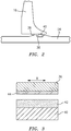
- FIG. 2 shows IBR 16, and specifically a counterface 36 of IBR 16, as well as a portion of outer shaft 26 against which a seal is needed.
- a radially outwardly facing groove 38 can be defined on outer shaft 26, and a seal 40 can be disposed in groove 38 for sealing against counterface 36.
- seal 40 is considered a high pressure compressor piston-seal. Lubrication of the interface between seal 40 and counterface 36 is the focus of the present disclosure.
- FIG. 3 is an enlarged view of the interface between seal 40 and counterface 36.
- a high energy vibratory motion is encountered by the seal and counterface, which is schematically represented by arrow B.
- This vibratory motion especially at the elevated temperatures to which this area is subjected, namely between about 350 and 900 °F (177 - 482 °C), can lead to rapid failure or at least wear of seal 40, which can in turn lead to damage to counterface 36 of the IBR, which leads to costly overhaul.
- Seal 40 is typically a ring seal which can be fabricated from a nickel, cobalt or iron superalloy.
- suitable material include IN 718 nickel superalloy, Haynes 25 cobalt alloy and A286 iron based superalloy, and numerous other examples of other suitable materials would be well known to a person having ordinary skill in the art.
- the counterface 36 of IBR 16 can typically be fabricated from a nickel based superalloy such as DA718. This material would typically be the material from which at least this portion of the IBR is fabricated.
- a coating 42 ( FIG. 3 ) can be applied to seal 40, wherein the coating 42 is a lubricant coating that reduces friction and wear between seal 40 and counterface 36 due to excessive heat and vibratory movement or fretting.
- This lubricant coating in the disclosed embodiment, is applied to an outer radius of the ring shaped seal so as to be positioned for sealing interaction with counterface 36.
- Lubricant coating 42 is advantageously provided from a CoCrAlY alloy, which can advantageously be blended with hBN.
- a specific example of a suitable blend of these materials is AMDRY-958 provided by Oerlikon Metco which is a particularly well-suited lubricant coating for use in the seal system of the present disclosure.
- the lubricant coating in this non-limiting embodiment can by provided as a mixture of between about 75 and 98% wt. CoCrAlY and between about 2 and 25% wt. hBN, although other ratios of components can also be utilized.
- One particularly suitable blend is 85% wt. CoCrAlY and 15% wt. hBN.
- lubricant coating 42 advantageously has a thickness of between about 0.001 and about 0.006 inches (0.0254 - 0.1524mm), preferably between about, more preferably between 0.003 and 0.005 inches (0.0762 - 0.127mm).
- Lubricant coating 42 can advantageously be produced on seal 40 in numerous different ways, but one particularly well suited but non-limiting example of application method is through plasma spray.
- counterface 36 can also be provided with an additional lubricant coating 44.
- Additional lubricant coating 44 can be hBN or an hBN-based solid lubricant paste, which can be applied to counterface 36. This additional lubricant coating helps to further reduce friction between counterface 36 and seal 40.
- the solid lubricant may suitably contain less than about 10% wt. of binder constituents.
- This coating can have a thickness of between about 0.0001 and about 0.002 (0.00254 - 0.0508mm), preferably between 0.0005 and 0.001 inches (0.0127 - 0.0254mm).
- the additional lubricant coating can be applied to IBR counterface 36 by brushing or swabbing, as non-limiting examples.
- the additional lubricant coating can be applied by spraying, or other suitable methods.
- the paste When applied as a solid lubricant paste, the paste can then suitable be cured at elevated temperature to produce the desired additional lubricant coating.
- Lubricant coating 42 alone produces an improved sliding regime between the seal ring 40 and counterface 36 as compared to the conventional structures mentioned above. This serves to reduce overall wear of the interface between the seal and counterface. Further, adding additional lubricant coating 44 to counterface 36 of the IBR even further reduces overall wear at the interface, and thereby can greatly reduce the cost and frequency of repair and overhaul of these components.
- Additional lubricant coating 44 can also reduce the breaking-in period between the surfaces. More specifically, upon initial motion, basal planes of the additional lubricant coating (hBN) become parallel to the sliding direction, thereby reducing the coefficient of friction.
- hBN additional lubricant coating
- FIG. 4 shows the results of this testing in terms of normalized wear volume for piston seal coating and counterface of the IBR.
- data on the left side of the drawing shows wear of the piston seal-coating at 50, and wear of the counterface of the IBR at 52. As shown, there was considerable wear to the IBR.
- wear on the piston seal-coating of the inventive coating system is shown at 54, and there was no measurable wear to the IBR counterface.
- Low friction and wear resistant piston seals or rings as disclosed herein are capable of operating efficiently in high pressure compressor static sealing applications and will significantly increase the endurance life of engine components.
- this technology may significantly reduce overhaul costs by reducing the number of parts (in particular the more-expensive counterparts) that are stripped due to wear and thermal damage issues (e.g. caused by frictional heating).
Landscapes
- Chemical & Material Sciences (AREA)
- Engineering & Computer Science (AREA)
- Mechanical Engineering (AREA)
- Organic Chemistry (AREA)
- Chemical Kinetics & Catalysis (AREA)
- Materials Engineering (AREA)
- Metallurgy (AREA)
- General Engineering & Computer Science (AREA)
- Plasma & Fusion (AREA)
- Physics & Mathematics (AREA)
- Inorganic Chemistry (AREA)
- Combustion & Propulsion (AREA)
- Structures Of Non-Positive Displacement Pumps (AREA)
Abstract
Description
- The present disclosure relates to a compressor seal-ring assembly and, more particularly, to a high-pressure compressor seal-ring assembly with a coating system to improve wear resistance.
- Gas turbine engines typically include compressors having multiple rows, or stages, of rotating blades and multiple stages of stators. In some parts of the gas turbine engine, it is desirable to create a seal between two volumes. For example, a first volume can define a portion of the gas path which receives relatively hot fluid. Fluid within a second volume can be used to cool components of the gas turbine engine and, thus, have a lower temperature than the fluid within the first volume. A seal can be used to seal the first volume from the second volume as some parts defining the first and/or second volume move and/or rotate with respect to other parts defining the first and/or second volume.
- One specific location of a seal in such an engine is between components of a high pressure compressor, for example between a rotor such as an integrated blade rotor (IBR) and a shaft on which the IBR is positioned.
- In some high pressure compressor piston-seals, operation is carried out at elevated temperatures and conditions of high vibratory motion. Existing seal rings are typically manufactured from, or provided having outer surfaces of, a nickel superalloy such as IN718, which can typically be coated with a copper aluminum alloy. The corresponding surface of the IBR is typically fabricated from a nickel based superalloy such as DA718. Due to poor tribological behavior of these alloys in combination with the high temperature exposure and high vibratory energy in the system, these materials are not capable of effectively operating under the harsh conditions, continuously resulting in premature failure of the seal due to wear issues.
- In addition to the need to constantly replace such seals after excessive wear, this situation can also frequently cause costly damage to other parts, such as to the counterface of the IBR, which is a critical and expensive part.
- The present disclosure is directed to addressing this issue.
- A compressor seal-ring assembly according to one embodiment of the present disclosure comprises a seal comprising a nickel, cobalt or iron-based superalloy; a counterface positioned for sealing interaction with the seal; and a lubricant coating on the seal, the lubricant coating comprising a CoCrAlY-containing material.
- In one non-limiting embodiment, the lubricant coating has a thickness of between 0.001 and 0.006 inches (0.0254 - 0.1524mm).
- In another non-limiting embodiment, the lubricant coating has a thickness of between 0.003 and 0.005 inches (0.0762 - 0.127mm) .
- In a further non-limiting embodiment, the lubricant coating comprises between 75 and 98 % wt. of CoCrAlY and between 2 and 25 % wt. of hBN.
- In still another non-limiting embodiment, the assembly further comprises an additional lubricant coating on the counterface.
- In a still further non-limiting embodiment, the additional lubricant coating comprises hBN.
- In another non-limiting embodiment, the additional lubricant coating has a thickness of between 0.0001 and 0.002 inches (0.00254 - 0.0508mm).
- In a further non-limiting embodiment, the additional lubricant coating has a thickness of between 0.0005 and 0.001 inches (0.0127 - 0.0254mm).
- In another non-limiting embodiment, the additional lubricant coating is a solid lubricant paste.
- In still another non-limiting embodiment, the solid lubricant paste contains < 10% wt. of binder constituents.
- In another non-limiting embodiment, the counterface is a surface of a rotor, and the seal is mounted between the rotor and an outer shaft on which the rotor is mounted.
- In a non-limiting embodiment, a method for improving wear resistance of a compressor seal-ring assembly comprises positioning a seal comprising a nickel, cobalt or iron-based superalloy for sealing interaction with a counterface, wherein the seal has a lubricant coating comprising a CoCrAlY material; and moving the counterface relative to the seal to deposit a transfer coating from the lubricant coating on the counterface.
- In another non-limiting embodiment, the transfer coating creates a Co-Co interface between the seal and the counterface.
- In a further non-limiting embodiment, the counterface is a surface of a rotor.
- In still another non-limiting embodiment, the method further comprises applying an additional lubricant coating to the counterface.
- In a still further non-limiting embodiment, the additional lubricant coating comprises hBN.
- In another non-limiting embodiment, the additional lubricant coating is applied as a solid lubricant paste, and the method further comprises curing the solid lubricant paste to produce the additional lubricant coating.
- The details of one or more embodiments of the invention are set forth in the accompanying drawings and the description below. Other features, objects, and advantages of the invention will be apparent from the description and drawings, and from the claims.
- A detailed description of preferred embodiments of the present disclosure follows, with referenced to the attached drawings, wherein:
-
FIG. 1 illustrates a portion of a gas turbine engine showing the environment surrounding a seal assembly of the present disclosure; -
FIG. 2 is an enlarged portion ofFIG. 1 showing a non-limiting embodiment of the disclosed seal assembly; -
FIG. 3 shows a cross-section taken through a seal and counterface of a compressor seal-ring assembly according to the present disclosure; and -
FIG. 4 illustrates the wear results of the presently disclosed system as compared to a prior art system as discussed above. - Like reference numbers and designations in the various drawings indicate like elements.
- The disclosure relates to a compressor seal-ring assembly and more particularly to a coating system for use with a seal ring and associated rotor such as an integrated blade rotor (IBR).
-
FIG. 1 showshigh pressure compressor 10 which includes a plurality of integrally bladed rotors (IBR) includingIBRs rotor disk portion 18 and ablade portion 20.Rotor disk portion 18 andblade portion 20 are portions of a single component. Similar components are present in the other IBRs as well. -
High pressure compressor 10 includes ahub rotor 22 having a radiallyinner arm 24 coupled toouter shaft 26 via anengine nut 28. Aseal ring 30 is positioned between anouter arm 32 ofhub rotor 22 and a portion ofrotor disk portion 18 of IBR 12. A rotor stack 34 (includingIBRs high pressure compressor 10 is coupled toouter shaft 26 at a location forward ofIBR 16. In that regard,rotor stack 34 andseal ring 30 are held in place via compressive force applied via the coupling ofrotor stack 34 toouter shaft 26 at the forward location and via the coupling ofhub rotor 22 toouter shaft 26. Compressive force is defined as a force applied to an object from two sides that does not necessarily cause the object to reduce in size, quantity or volume. Stated differently,seal ring 30 is held in place by compressive force applied toseal ring 30 as a result of a forward force applied byhub rotor 22 and an aftward force applied byIBR 12. In that regard,seal ring 30 can be press fit into place betweenouter arm 32 ofhub rotor 22 androtor disk portion 18 of IBR 12. - IBR 16 is shown sealed against
outer shaft 26 at the portion circled at A, which is enlarged inFIG. 2 . -
FIG. 2 shows IBR 16, and specifically acounterface 36 of IBR 16, as well as a portion ofouter shaft 26 against which a seal is needed. As shown, a radially outwardly facinggroove 38 can be defined onouter shaft 26, and aseal 40 can be disposed ingroove 38 for sealing againstcounterface 36. In this location,seal 40 is considered a high pressure compressor piston-seal. Lubrication of the interface betweenseal 40 andcounterface 36 is the focus of the present disclosure. -
FIG. 3 is an enlarged view of the interface betweenseal 40 andcounterface 36. At this location, a high energy vibratory motion is encountered by the seal and counterface, which is schematically represented by arrow B. This vibratory motion, especially at the elevated temperatures to which this area is subjected, namely between about 350 and 900 °F (177 - 482 °C), can lead to rapid failure or at least wear ofseal 40, which can in turn lead to damage to counterface 36 of the IBR, which leads to costly overhaul. - In high detail photography of a conventional seal and corresponding IBR surface after a certain amount of operation of these components at high temperatures and high conditions of vibratory energy, the surface of the seal is worn and damaged, and a corresponding portion of the surface of the IBR is also visibly pitted and worn in a manner which can require expensive and time-consuming repair and/or replacement. The lubricant system disclosed herein addresses this problem.
-
Seal 40 is typically a ring seal which can be fabricated from a nickel, cobalt or iron superalloy. Specific non-limiting examples of suitable material include IN 718 nickel superalloy, Haynes 25 cobalt alloy and A286 iron based superalloy, and numerous other examples of other suitable materials would be well known to a person having ordinary skill in the art. - The
counterface 36 ofIBR 16 can typically be fabricated from a nickel based superalloy such as DA718. This material would typically be the material from which at least this portion of the IBR is fabricated. - In conventional seals, a coating is produced on the seal, wherein the conventional coating is a copper aluminum alloy. This coating has been found to be insufficient, and results in the unacceptable wear discussed above. Therefore, as disclosed herein, a coating 42 (
FIG. 3 ) can be applied to seal 40, wherein thecoating 42 is a lubricant coating that reduces friction and wear betweenseal 40 andcounterface 36 due to excessive heat and vibratory movement or fretting. This lubricant coating, in the disclosed embodiment, is applied to an outer radius of the ring shaped seal so as to be positioned for sealing interaction withcounterface 36. -
Lubricant coating 42 is advantageously provided from a CoCrAlY alloy, which can advantageously be blended with hBN. A specific example of a suitable blend of these materials is AMDRY-958 provided by Oerlikon Metco which is a particularly well-suited lubricant coating for use in the seal system of the present disclosure. The lubricant coating in this non-limiting embodiment can by provided as a mixture of between about 75 and 98% wt. CoCrAlY and between about 2 and 25% wt. hBN, although other ratios of components can also be utilized. One particularly suitable blend is 85% wt. CoCrAlY and 15% wt. hBN. Further,lubricant coating 42 advantageously has a thickness of between about 0.001 and about 0.006 inches (0.0254 - 0.1524mm), preferably between about, more preferably between 0.003 and 0.005 inches (0.0762 - 0.127mm). -
Lubricant coating 42 can advantageously be produced onseal 40 in numerous different ways, but one particularly well suited but non-limiting example of application method is through plasma spray. - In a further non-limiting embodiment,
counterface 36 can also be provided with anadditional lubricant coating 44.Additional lubricant coating 44 can be hBN or an hBN-based solid lubricant paste, which can be applied tocounterface 36. This additional lubricant coating helps to further reduce friction betweencounterface 36 andseal 40. The solid lubricant may suitably contain less than about 10% wt. of binder constituents. This coating can have a thickness of between about 0.0001 and about 0.002 (0.00254 - 0.0508mm), preferably between 0.0005 and 0.001 inches (0.0127 - 0.0254mm). - The additional lubricant coating can be applied to
IBR counterface 36 by brushing or swabbing, as non-limiting examples. Alternatively, the additional lubricant coating can be applied by spraying, or other suitable methods. When applied as a solid lubricant paste, the paste can then suitable be cured at elevated temperature to produce the desired additional lubricant coating. -
Lubricant coating 42 alone produces an improved sliding regime between theseal ring 40 andcounterface 36 as compared to the conventional structures mentioned above. This serves to reduce overall wear of the interface between the seal and counterface. Further, addingadditional lubricant coating 44 to counterface 36 of the IBR even further reduces overall wear at the interface, and thereby can greatly reduce the cost and frequency of repair and overhaul of these components. -
Additional lubricant coating 44 can also reduce the breaking-in period between the surfaces. More specifically, upon initial motion, basal planes of the additional lubricant coating (hBN) become parallel to the sliding direction, thereby reducing the coefficient of friction. - Wear volume was measured for a prior art coating system having a copper aluminum alloy coating on the seal, and also for a coating system of the present disclosure including an 85%/15% lubricant coating of CoCrAlY and hBN as discussed above, applied to the seal with no additional coating on the IBR. These tests were conducted on a custom build rig with a pin-on-flat configuration.
FIG. 4 shows the results of this testing in terms of normalized wear volume for piston seal coating and counterface of the IBR. InFIG. 4 , data on the left side of the drawing shows wear of the piston seal-coating at 50, and wear of the counterface of the IBR at 52. As shown, there was considerable wear to the IBR. On the right side of the drawing, wear on the piston seal-coating of the inventive coating system is shown at 54, and there was no measurable wear to the IBR counterface. - In the left side of
FIG. 4 , using conventional seal and coating, significant wear volume is shown, for both components. In the right-side portion ofFIG. 4 , it can be seen that the wear volume is slightly higher on the piston seal/coating side, but is virtually eliminated on the counterface side. The slight increase in piston seal-coating wear is accounted for by creation of a transfer coating on the counterface surface of the IBR. This is desirable, as the transfer coating consists of cobalt from the CoCrAlY lubricant coating which is positioned on the seal, and this transfer coating creates a cobalt-cobalt sliding regime between the seal and counterface. This sliding regime is subject to extremely low friction and greatly reduces or eliminates wear problems due to the high vibratory energy encountered in this interface, as well as the high temperatures. Thus, the lubricant system of the present disclosure greatly reduces or eliminates wear to the expensive IBR component. - It should be noted that the testing conducted as represented in
FIG. 4 was conducted without utilizing the additional lubricant coating on the counterface or IBR side as discussed above. With this optional additional lubricant coating, the wear can be even more greatly reduced. - Low friction and wear resistant piston seals or rings as disclosed herein are capable of operating efficiently in high pressure compressor static sealing applications and will significantly increase the endurance life of engine components. In addition, this technology may significantly reduce overhaul costs by reducing the number of parts (in particular the more-expensive counterparts) that are stripped due to wear and thermal damage issues (e.g. caused by frictional heating).
- One or more embodiments of the present invention have been described. Nevertheless, it will be understood that various modifications may be made without departing from the spirit and scope of the invention. For example, the disclosed lubricant coatings can be applied at other similar locations within a gas turbine engine and produce benefits from such application as well. Further, the coating materials disclosed herein and their equivalents can be utilized with components of different underlying materials, all within the broad scope of the disclosure. Accordingly, other embodiments are within the scope of the following claims.
Claims (15)
- A compressor seal-ring assembly, comprising:a seal (40) comprising a nickel, cobalt or iron-based superalloy;a counterface (36) positioned for sealing interaction with the seal (40); anda lubricant coating (42) on the seal (40), the lubricant coating (42) comprising a CoCrAlY-containing material.
- The assembly of claim 1, wherein the lubricant coating (42) has a thickness of between 0.001 and 0.006 inches (0.0254 - 0.1524mm), wherein, optionally, the lubricant coating (42) has a thickness of between 0.003 and 0.005 inches (0.0762 - 0.127mm).
- The assembly of claim 1 or 2, wherein the lubricant coating (42) comprises between 75 and 98 % wt. of CoCrAlY and between 2 and 25 % wt. of hBN.
- The assembly of claim 1, 2 or 3, further comprising an additional lubricant (44) coating on the counterface (36).
- The assembly of claim 4, wherein the additional lubricant coating (44) comprises hBN.
- The assembly of claim 4 or 5, wherein the additional lubricant coating (44) has a thickness of between 0.0001 and 0.002 inches (0.00254 - 0.0508mm), wherein, optionally, the additional lubricant coating (44) has a thickness of between 0.0005 and 0.001 inches (0.0127-0.0254mm).
- The assembly of claim 4, 5 or 6, wherein the additional lubricant coating (44) is a solid lubricant paste, and wherein, optionally, the solid lubricant paste contains < 10% wt. of binder constituents.
- The assembly of any preceding claim, wherein the counterface (36) is a surface of a rotor (16), and the seal (40) is mounted between the rotor (16) and an outer shaft (26) on which the rotor (16) is mounted.
- The assembly of claim 8, wherein the rotor (16) is a component of a high pressure compressor (10) of a gas turbine engine.
- A method for improving wear resistance of a compressor seal-ring assembly, comprising:positioning a seal (40) comprising a nickel, cobalt or iron-based superalloy for sealing interaction with a counterface (36), wherein the seal has a lubricant coating (42) comprising a CoCrAlY material; andmoving the counterface relative to the seal (40) to deposit a transfer coating from the lubricant coating (42) on the counterface (36).
- The method of claim 10, wherein the transfer coating creates a Co-Co interface between the seal (40) and the counterface (36).
- The method of claim 10 or 11, wherein the counterface (36) is a surface of a rotor (16).
- The method of claim 10, 11 or 12, further comprising the step of applying an additional lubricant coating (44) to the counterface (36).
- The method of claim 13, wherein the additional lubricant coating (44) comprises hBN.
- The method of claim 13 or 14, wherein the additional lubricant coating (44) is applied as a solid lubricant paste, and further comprising curing the solid lubricant paste to produce the additional lubricant coating (44).
Applications Claiming Priority (1)
| Application Number | Priority Date | Filing Date | Title |
|---|---|---|---|
| US16/269,673 US11149854B2 (en) | 2019-02-07 | 2019-02-07 | High pressure compressor seal-ring with improved wear resistance |
Publications (2)
| Publication Number | Publication Date |
|---|---|
| EP3693556A1 true EP3693556A1 (en) | 2020-08-12 |
| EP3693556B1 EP3693556B1 (en) | 2023-09-06 |
Family
ID=69528569
Family Applications (1)
| Application Number | Title | Priority Date | Filing Date |
|---|---|---|---|
| EP20156101.6A Active EP3693556B1 (en) | 2019-02-07 | 2020-02-07 | High pressure compressor seal-ring with improved wear resistance |
Country Status (2)
| Country | Link |
|---|---|
| US (2) | US11149854B2 (en) |
| EP (1) | EP3693556B1 (en) |
Cited By (1)
| Publication number | Priority date | Publication date | Assignee | Title |
|---|---|---|---|---|
| WO2026064506A1 (en) * | 2024-09-18 | 2026-03-26 | Rtx Corporation | Turbine engine rotor piston seal ring contact hard coatings |
Families Citing this family (1)
| Publication number | Priority date | Publication date | Assignee | Title |
|---|---|---|---|---|
| US11542819B2 (en) * | 2021-02-17 | 2023-01-03 | Pratt & Whitney Canada Corp. | Split ring seal for gas turbine engine rotor |
Citations (3)
| Publication number | Priority date | Publication date | Assignee | Title |
|---|---|---|---|---|
| US4152223A (en) * | 1977-07-13 | 1979-05-01 | United Technologies Corporation | Plasma sprayed MCrAlY coating and coating method |
| US4750746A (en) * | 1986-09-17 | 1988-06-14 | Societe Nationale D'etude Et De Construction De Moteurs D'aviation (Snecma) | Device for attaching a seal member to a shaft |
| US20130051993A1 (en) * | 2011-08-24 | 2013-02-28 | Scot A. Webb | Rotating turbomachine seal |
Family Cites Families (8)
| Publication number | Priority date | Publication date | Assignee | Title |
|---|---|---|---|---|
| JP4921894B2 (en) * | 2006-08-30 | 2012-04-25 | 住鉱潤滑剤株式会社 | Multi-layer lubricating coating composition, multi-layer lubricating coating and piston having the coating |
| US20110027573A1 (en) * | 2009-08-03 | 2011-02-03 | United Technologies Corporation | Lubricated Abradable Coating |
| JP2012067878A (en) * | 2010-09-24 | 2012-04-05 | Mitsubishi Heavy Ind Ltd | Self-adjusting seal for turbo rotary machine |
| EP3027870B1 (en) * | 2013-08-02 | 2019-05-15 | United Technologies Corporation | Gas turbine engine non-rotating structure wedge seal |
| US20150093237A1 (en) * | 2013-09-30 | 2015-04-02 | General Electric Company | Ceramic matrix composite component, turbine system and fabrication process |
| US9957826B2 (en) * | 2014-06-09 | 2018-05-01 | United Technologies Corporation | Stiffness controlled abradeable seal system with max phase materials and methods of making same |
| US9995161B2 (en) * | 2014-11-12 | 2018-06-12 | Borgwarner Inc. | Modular turbocharger clearance seal |
| US20180291815A1 (en) * | 2017-04-10 | 2018-10-11 | Rolls-Royce Corporation | Reduced friction intershaft seal assembly |
-
2019
- 2019-02-07 US US16/269,673 patent/US11149854B2/en active Active
-
2020
- 2020-02-07 EP EP20156101.6A patent/EP3693556B1/en active Active
-
2021
- 2021-07-02 US US17/366,259 patent/US11739842B2/en active Active
Patent Citations (3)
| Publication number | Priority date | Publication date | Assignee | Title |
|---|---|---|---|---|
| US4152223A (en) * | 1977-07-13 | 1979-05-01 | United Technologies Corporation | Plasma sprayed MCrAlY coating and coating method |
| US4750746A (en) * | 1986-09-17 | 1988-06-14 | Societe Nationale D'etude Et De Construction De Moteurs D'aviation (Snecma) | Device for attaching a seal member to a shaft |
| US20130051993A1 (en) * | 2011-08-24 | 2013-02-28 | Scot A. Webb | Rotating turbomachine seal |
Cited By (1)
| Publication number | Priority date | Publication date | Assignee | Title |
|---|---|---|---|---|
| WO2026064506A1 (en) * | 2024-09-18 | 2026-03-26 | Rtx Corporation | Turbine engine rotor piston seal ring contact hard coatings |
Also Published As
| Publication number | Publication date |
|---|---|
| EP3693556B1 (en) | 2023-09-06 |
| US20210372525A1 (en) | 2021-12-02 |
| US20200256467A1 (en) | 2020-08-13 |
| US11739842B2 (en) | 2023-08-29 |
| US11149854B2 (en) | 2021-10-19 |
Similar Documents
| Publication | Publication Date | Title |
|---|---|---|
| EP3009612B1 (en) | Non-contacting seal | |
| US6533285B2 (en) | Abradable coating and method of production | |
| Delebarre et al. | An experimental study of the high speed interaction between a labyrinth seal and an abradable coating in a turbo-engine application | |
| EP2955331B1 (en) | Stiffness controlled abradeable seal system and method of making same | |
| Bill et al. | Wear of seal materials used in aircraft propulsion systems | |
| US10465536B2 (en) | Gas turbine engine component with an abrasive coating | |
| US11739842B2 (en) | High pressure compressor seal-ring with improved wear resistance | |
| JP2008063657A (en) | How to apply high temperature resistant fretting wear coatings | |
| Sporer et al. | On The Potential Of Metal And Ceramic Based Abradables In Turbine Seal Applications. | |
| Johnson et al. | Fretting in aircraft turbine engines | |
| CN103890320A (en) | High temperature sealing system | |
| JP4223935B2 (en) | Abrasive seal powder material | |
| EP3626851A1 (en) | Low friction, wear resistant dry face carbon seal - seal seat assembly | |
| JP7065715B2 (en) | Foil bearings, foil bearing units, turbomachinery, foil bearing manufacturing methods | |
| JPH07247804A (en) | Rotor and blade assemblies for gas turbine engines, and multilayer coated shims | |
| US11448082B2 (en) | Wear resistant, self-lubricating static seal | |
| US10794210B2 (en) | Stiffness controlled abradeable seal system and methods of making same | |
| CN113981356A (en) | Spraying powder particles for aeroengine sealing coating | |
| EP2969260B1 (en) | Anti-fret coating system | |
| Chupp et al. | Development of higher temperature abradable seals for gas turbine applications | |
| Chupp et al. | Advanced seals for industrial turbine applications | |
| EP3954869B1 (en) | Coating for a blade root/disk interface and coated blade root/disk interface | |
| Munz et al. | Numerical investigations on the rubbing process in labyrinth seals for full flight mission | |
| Belousov et al. | Research and Development of the Joint Seals for Gas Turbine Engine High-Temperature Turbine Stator Units | |
| Uihlein et al. | Airseals for Advanced Mititäry Jet Engines |
Legal Events
| Date | Code | Title | Description |
|---|---|---|---|
| PUAI | Public reference made under article 153(3) epc to a published international application that has entered the european phase |
Free format text: ORIGINAL CODE: 0009012 |
|
| STAA | Information on the status of an ep patent application or granted ep patent |
Free format text: STATUS: THE APPLICATION HAS BEEN PUBLISHED |
|
| AK | Designated contracting states |
Kind code of ref document: A1 Designated state(s): AL AT BE BG CH CY CZ DE DK EE ES FI FR GB GR HR HU IE IS IT LI LT LU LV MC MK MT NL NO PL PT RO RS SE SI SK SM TR |
|
| AX | Request for extension of the european patent |
Extension state: BA ME |
|
| STAA | Information on the status of an ep patent application or granted ep patent |
Free format text: STATUS: REQUEST FOR EXAMINATION WAS MADE |
|
| 17P | Request for examination filed |
Effective date: 20210212 |
|
| RAP1 | Party data changed (applicant data changed or rights of an application transferred) |
Owner name: RAYTHEON TECHNOLOGIES CORPORATION |
|
| RBV | Designated contracting states (corrected) |
Designated state(s): AL AT BE BG CH CY CZ DE DK EE ES FI FR GB GR HR HU IE IS IT LI LT LU LV MC MK MT NL NO PL PT RO RS SE SI SK SM TR |
|
| STAA | Information on the status of an ep patent application or granted ep patent |
Free format text: STATUS: EXAMINATION IS IN PROGRESS |
|
| 17Q | First examination report despatched |
Effective date: 20210610 |
|
| GRAP | Despatch of communication of intention to grant a patent |
Free format text: ORIGINAL CODE: EPIDOSNIGR1 |
|
| STAA | Information on the status of an ep patent application or granted ep patent |
Free format text: STATUS: GRANT OF PATENT IS INTENDED |
|
| INTG | Intention to grant announced |
Effective date: 20230324 |
|
| GRAS | Grant fee paid |
Free format text: ORIGINAL CODE: EPIDOSNIGR3 |
|
| GRAA | (expected) grant |
Free format text: ORIGINAL CODE: 0009210 |
|
| STAA | Information on the status of an ep patent application or granted ep patent |
Free format text: STATUS: THE PATENT HAS BEEN GRANTED |
|
| AK | Designated contracting states |
Kind code of ref document: B1 Designated state(s): AL AT BE BG CH CY CZ DE DK EE ES FI FR GB GR HR HU IE IS IT LI LT LU LV MC MK MT NL NO PL PT RO RS SE SI SK SM TR |
|
| REG | Reference to a national code |
Ref country code: GB Ref legal event code: FG4D |
|
| REG | Reference to a national code |
Ref country code: CH Ref legal event code: EP |
|
| REG | Reference to a national code |
Ref country code: IE Ref legal event code: FG4D |
|
| REG | Reference to a national code |
Ref country code: DE Ref legal event code: R096 Ref document number: 602020016990 Country of ref document: DE |
|
| RAP4 | Party data changed (patent owner data changed or rights of a patent transferred) |
Owner name: RTX CORPORATION |
|
| REG | Reference to a national code |
Ref country code: LT Ref legal event code: MG9D |
|
| REG | Reference to a national code |
Ref country code: NL Ref legal event code: MP Effective date: 20230906 |
|
| PG25 | Lapsed in a contracting state [announced via postgrant information from national office to epo] |
Ref country code: GR Free format text: LAPSE BECAUSE OF FAILURE TO SUBMIT A TRANSLATION OF THE DESCRIPTION OR TO PAY THE FEE WITHIN THE PRESCRIBED TIME-LIMIT Effective date: 20231207 |
|
| PG25 | Lapsed in a contracting state [announced via postgrant information from national office to epo] |
Ref country code: SE Free format text: LAPSE BECAUSE OF FAILURE TO SUBMIT A TRANSLATION OF THE DESCRIPTION OR TO PAY THE FEE WITHIN THE PRESCRIBED TIME-LIMIT Effective date: 20230906 Ref country code: RS Free format text: LAPSE BECAUSE OF FAILURE TO SUBMIT A TRANSLATION OF THE DESCRIPTION OR TO PAY THE FEE WITHIN THE PRESCRIBED TIME-LIMIT Effective date: 20230906 Ref country code: NO Free format text: LAPSE BECAUSE OF FAILURE TO SUBMIT A TRANSLATION OF THE DESCRIPTION OR TO PAY THE FEE WITHIN THE PRESCRIBED TIME-LIMIT Effective date: 20231206 Ref country code: LV Free format text: LAPSE BECAUSE OF FAILURE TO SUBMIT A TRANSLATION OF THE DESCRIPTION OR TO PAY THE FEE WITHIN THE PRESCRIBED TIME-LIMIT Effective date: 20230906 Ref country code: LT Free format text: LAPSE BECAUSE OF FAILURE TO SUBMIT A TRANSLATION OF THE DESCRIPTION OR TO PAY THE FEE WITHIN THE PRESCRIBED TIME-LIMIT Effective date: 20230906 Ref country code: HR Free format text: LAPSE BECAUSE OF FAILURE TO SUBMIT A TRANSLATION OF THE DESCRIPTION OR TO PAY THE FEE WITHIN THE PRESCRIBED TIME-LIMIT Effective date: 20230906 Ref country code: GR Free format text: LAPSE BECAUSE OF FAILURE TO SUBMIT A TRANSLATION OF THE DESCRIPTION OR TO PAY THE FEE WITHIN THE PRESCRIBED TIME-LIMIT Effective date: 20231207 Ref country code: FI Free format text: LAPSE BECAUSE OF FAILURE TO SUBMIT A TRANSLATION OF THE DESCRIPTION OR TO PAY THE FEE WITHIN THE PRESCRIBED TIME-LIMIT Effective date: 20230906 |
|
| REG | Reference to a national code |
Ref country code: AT Ref legal event code: MK05 Ref document number: 1608822 Country of ref document: AT Kind code of ref document: T Effective date: 20230906 |
|
| PG25 | Lapsed in a contracting state [announced via postgrant information from national office to epo] |
Ref country code: NL Free format text: LAPSE BECAUSE OF FAILURE TO SUBMIT A TRANSLATION OF THE DESCRIPTION OR TO PAY THE FEE WITHIN THE PRESCRIBED TIME-LIMIT Effective date: 20230906 |
|
| PG25 | Lapsed in a contracting state [announced via postgrant information from national office to epo] |
Ref country code: IS Free format text: LAPSE BECAUSE OF FAILURE TO SUBMIT A TRANSLATION OF THE DESCRIPTION OR TO PAY THE FEE WITHIN THE PRESCRIBED TIME-LIMIT Effective date: 20240106 |
|
| PG25 | Lapsed in a contracting state [announced via postgrant information from national office to epo] |
Ref country code: AT Free format text: LAPSE BECAUSE OF FAILURE TO SUBMIT A TRANSLATION OF THE DESCRIPTION OR TO PAY THE FEE WITHIN THE PRESCRIBED TIME-LIMIT Effective date: 20230906 |
|
| PG25 | Lapsed in a contracting state [announced via postgrant information from national office to epo] |
Ref country code: ES Free format text: LAPSE BECAUSE OF FAILURE TO SUBMIT A TRANSLATION OF THE DESCRIPTION OR TO PAY THE FEE WITHIN THE PRESCRIBED TIME-LIMIT Effective date: 20230906 |
|
| PG25 | Lapsed in a contracting state [announced via postgrant information from national office to epo] |
Ref country code: SM Free format text: LAPSE BECAUSE OF FAILURE TO SUBMIT A TRANSLATION OF THE DESCRIPTION OR TO PAY THE FEE WITHIN THE PRESCRIBED TIME-LIMIT Effective date: 20230906 Ref country code: RO Free format text: LAPSE BECAUSE OF FAILURE TO SUBMIT A TRANSLATION OF THE DESCRIPTION OR TO PAY THE FEE WITHIN THE PRESCRIBED TIME-LIMIT Effective date: 20230906 Ref country code: IS Free format text: LAPSE BECAUSE OF FAILURE TO SUBMIT A TRANSLATION OF THE DESCRIPTION OR TO PAY THE FEE WITHIN THE PRESCRIBED TIME-LIMIT Effective date: 20240106 Ref country code: ES Free format text: LAPSE BECAUSE OF FAILURE TO SUBMIT A TRANSLATION OF THE DESCRIPTION OR TO PAY THE FEE WITHIN THE PRESCRIBED TIME-LIMIT Effective date: 20230906 Ref country code: EE Free format text: LAPSE BECAUSE OF FAILURE TO SUBMIT A TRANSLATION OF THE DESCRIPTION OR TO PAY THE FEE WITHIN THE PRESCRIBED TIME-LIMIT Effective date: 20230906 Ref country code: CZ Free format text: LAPSE BECAUSE OF FAILURE TO SUBMIT A TRANSLATION OF THE DESCRIPTION OR TO PAY THE FEE WITHIN THE PRESCRIBED TIME-LIMIT Effective date: 20230906 Ref country code: AT Free format text: LAPSE BECAUSE OF FAILURE TO SUBMIT A TRANSLATION OF THE DESCRIPTION OR TO PAY THE FEE WITHIN THE PRESCRIBED TIME-LIMIT Effective date: 20230906 Ref country code: SK Free format text: LAPSE BECAUSE OF FAILURE TO SUBMIT A TRANSLATION OF THE DESCRIPTION OR TO PAY THE FEE WITHIN THE PRESCRIBED TIME-LIMIT Effective date: 20230906 Ref country code: PT Free format text: LAPSE BECAUSE OF FAILURE TO SUBMIT A TRANSLATION OF THE DESCRIPTION OR TO PAY THE FEE WITHIN THE PRESCRIBED TIME-LIMIT Effective date: 20240108 |
|
| PG25 | Lapsed in a contracting state [announced via postgrant information from national office to epo] |
Ref country code: PL Free format text: LAPSE BECAUSE OF FAILURE TO SUBMIT A TRANSLATION OF THE DESCRIPTION OR TO PAY THE FEE WITHIN THE PRESCRIBED TIME-LIMIT Effective date: 20230906 Ref country code: IT Free format text: LAPSE BECAUSE OF FAILURE TO SUBMIT A TRANSLATION OF THE DESCRIPTION OR TO PAY THE FEE WITHIN THE PRESCRIBED TIME-LIMIT Effective date: 20230906 |
|
| REG | Reference to a national code |
Ref country code: DE Ref legal event code: R097 Ref document number: 602020016990 Country of ref document: DE |
|
| PG25 | Lapsed in a contracting state [announced via postgrant information from national office to epo] |
Ref country code: DK Free format text: LAPSE BECAUSE OF FAILURE TO SUBMIT A TRANSLATION OF THE DESCRIPTION OR TO PAY THE FEE WITHIN THE PRESCRIBED TIME-LIMIT Effective date: 20230906 |
|
| PLBE | No opposition filed within time limit |
Free format text: ORIGINAL CODE: 0009261 |
|
| STAA | Information on the status of an ep patent application or granted ep patent |
Free format text: STATUS: NO OPPOSITION FILED WITHIN TIME LIMIT |
|
| PG25 | Lapsed in a contracting state [announced via postgrant information from national office to epo] |
Ref country code: DK Free format text: LAPSE BECAUSE OF FAILURE TO SUBMIT A TRANSLATION OF THE DESCRIPTION OR TO PAY THE FEE WITHIN THE PRESCRIBED TIME-LIMIT Effective date: 20230906 Ref country code: SI Free format text: LAPSE BECAUSE OF FAILURE TO SUBMIT A TRANSLATION OF THE DESCRIPTION OR TO PAY THE FEE WITHIN THE PRESCRIBED TIME-LIMIT Effective date: 20230906 |
|
| 26N | No opposition filed |
Effective date: 20240607 |
|
| PG25 | Lapsed in a contracting state [announced via postgrant information from national office to epo] |
Ref country code: MC Free format text: LAPSE BECAUSE OF FAILURE TO SUBMIT A TRANSLATION OF THE DESCRIPTION OR TO PAY THE FEE WITHIN THE PRESCRIBED TIME-LIMIT Effective date: 20230906 |
|
| REG | Reference to a national code |
Ref country code: CH Ref legal event code: PL |
|
| PG25 | Lapsed in a contracting state [announced via postgrant information from national office to epo] |
Ref country code: LU Free format text: LAPSE BECAUSE OF NON-PAYMENT OF DUE FEES Effective date: 20240207 |
|
| PG25 | Lapsed in a contracting state [announced via postgrant information from national office to epo] |
Ref country code: CH Free format text: LAPSE BECAUSE OF NON-PAYMENT OF DUE FEES Effective date: 20240229 |
|
| PG25 | Lapsed in a contracting state [announced via postgrant information from national office to epo] |
Ref country code: LU Free format text: LAPSE BECAUSE OF NON-PAYMENT OF DUE FEES Effective date: 20240207 Ref country code: CH Free format text: LAPSE BECAUSE OF NON-PAYMENT OF DUE FEES Effective date: 20240229 |
|
| PG25 | Lapsed in a contracting state [announced via postgrant information from national office to epo] |
Ref country code: BG Free format text: LAPSE BECAUSE OF FAILURE TO SUBMIT A TRANSLATION OF THE DESCRIPTION OR TO PAY THE FEE WITHIN THE PRESCRIBED TIME-LIMIT Effective date: 20230906 |
|
| PG25 | Lapsed in a contracting state [announced via postgrant information from national office to epo] |
Ref country code: BG Free format text: LAPSE BECAUSE OF FAILURE TO SUBMIT A TRANSLATION OF THE DESCRIPTION OR TO PAY THE FEE WITHIN THE PRESCRIBED TIME-LIMIT Effective date: 20230906 |
|
| REG | Reference to a national code |
Ref country code: BE Ref legal event code: MM Effective date: 20240229 |
|
| PG25 | Lapsed in a contracting state [announced via postgrant information from national office to epo] |
Ref country code: BE Free format text: LAPSE BECAUSE OF NON-PAYMENT OF DUE FEES Effective date: 20240229 |
|
| PG25 | Lapsed in a contracting state [announced via postgrant information from national office to epo] |
Ref country code: IE Free format text: LAPSE BECAUSE OF NON-PAYMENT OF DUE FEES Effective date: 20240207 |
|
| PG25 | Lapsed in a contracting state [announced via postgrant information from national office to epo] |
Ref country code: IE Free format text: LAPSE BECAUSE OF NON-PAYMENT OF DUE FEES Effective date: 20240207 Ref country code: BE Free format text: LAPSE BECAUSE OF NON-PAYMENT OF DUE FEES Effective date: 20240229 |
|
| PG25 | Lapsed in a contracting state [announced via postgrant information from national office to epo] |
Ref country code: CY Free format text: LAPSE BECAUSE OF FAILURE TO SUBMIT A TRANSLATION OF THE DESCRIPTION OR TO PAY THE FEE WITHIN THE PRESCRIBED TIME-LIMIT; INVALID AB INITIO Effective date: 20200207 |
|
| PG25 | Lapsed in a contracting state [announced via postgrant information from national office to epo] |
Ref country code: HU Free format text: LAPSE BECAUSE OF FAILURE TO SUBMIT A TRANSLATION OF THE DESCRIPTION OR TO PAY THE FEE WITHIN THE PRESCRIBED TIME-LIMIT; INVALID AB INITIO Effective date: 20200207 |
|
| REG | Reference to a national code |
Ref country code: DE Ref legal event code: R081 Ref document number: 602020016990 Country of ref document: DE Owner name: RTX CORPORATION (N.D.GES.D. STAATES DELAWARE),, US Free format text: FORMER OWNER: RAYTHEON TECHNOLOGIES CORPORATION, FARMINGTON, CT, US |
|
| PG25 | Lapsed in a contracting state [announced via postgrant information from national office to epo] |
Ref country code: TR Free format text: LAPSE BECAUSE OF FAILURE TO SUBMIT A TRANSLATION OF THE DESCRIPTION OR TO PAY THE FEE WITHIN THE PRESCRIBED TIME-LIMIT Effective date: 20230906 |
|
| P01 | Opt-out of the competence of the unified patent court (upc) registered |
Free format text: CASE NUMBER: UPC_APP_0019192_3693556/2025 Effective date: 20251223 |
|
| PGFP | Annual fee paid to national office [announced via postgrant information from national office to epo] |
Ref country code: GB Payment date: 20260121 Year of fee payment: 7 |
|
| PGFP | Annual fee paid to national office [announced via postgrant information from national office to epo] |
Ref country code: DE Payment date: 20260121 Year of fee payment: 7 |
|
| PGFP | Annual fee paid to national office [announced via postgrant information from national office to epo] |
Ref country code: FR Payment date: 20260121 Year of fee payment: 7 |