EP3693555B1 - Face seal with damper - Google Patents
Face seal with damper Download PDFInfo
- Publication number
- EP3693555B1 EP3693555B1 EP20155676.8A EP20155676A EP3693555B1 EP 3693555 B1 EP3693555 B1 EP 3693555B1 EP 20155676 A EP20155676 A EP 20155676A EP 3693555 B1 EP3693555 B1 EP 3693555B1
- Authority
- EP
- European Patent Office
- Prior art keywords
- seal
- seal body
- gas turbine
- radial
- carrier
- Prior art date
- Legal status (The legal status is an assumption and is not a legal conclusion. Google has not performed a legal analysis and makes no representation as to the accuracy of the status listed.)
- Active
Links
Images

Classifications
-
- F—MECHANICAL ENGINEERING; LIGHTING; HEATING; WEAPONS; BLASTING
- F01—MACHINES OR ENGINES IN GENERAL; ENGINE PLANTS IN GENERAL; STEAM ENGINES
- F01D—NON-POSITIVE DISPLACEMENT MACHINES OR ENGINES, e.g. STEAM TURBINES
- F01D25/00—Component parts, details, or accessories, not provided for in, or of interest apart from, other groups
- F01D25/18—Lubricating arrangements
- F01D25/183—Sealing means
-
- F—MECHANICAL ENGINEERING; LIGHTING; HEATING; WEAPONS; BLASTING
- F01—MACHINES OR ENGINES IN GENERAL; ENGINE PLANTS IN GENERAL; STEAM ENGINES
- F01D—NON-POSITIVE DISPLACEMENT MACHINES OR ENGINES, e.g. STEAM TURBINES
- F01D11/00—Preventing or minimising internal leakage of working-fluid, e.g. between stages
- F01D11/003—Preventing or minimising internal leakage of working-fluid, e.g. between stages by packing rings; Mechanical seals
-
- F—MECHANICAL ENGINEERING; LIGHTING; HEATING; WEAPONS; BLASTING
- F01—MACHINES OR ENGINES IN GENERAL; ENGINE PLANTS IN GENERAL; STEAM ENGINES
- F01D—NON-POSITIVE DISPLACEMENT MACHINES OR ENGINES, e.g. STEAM TURBINES
- F01D11/00—Preventing or minimising internal leakage of working-fluid, e.g. between stages
- F01D11/005—Sealing means between non relatively rotating elements
-
- F—MECHANICAL ENGINEERING; LIGHTING; HEATING; WEAPONS; BLASTING
- F01—MACHINES OR ENGINES IN GENERAL; ENGINE PLANTS IN GENERAL; STEAM ENGINES
- F01D—NON-POSITIVE DISPLACEMENT MACHINES OR ENGINES, e.g. STEAM TURBINES
- F01D25/00—Component parts, details, or accessories, not provided for in, or of interest apart from, other groups
- F01D25/04—Antivibration arrangements
-
- F—MECHANICAL ENGINEERING; LIGHTING; HEATING; WEAPONS; BLASTING
- F01—MACHINES OR ENGINES IN GENERAL; ENGINE PLANTS IN GENERAL; STEAM ENGINES
- F01D—NON-POSITIVE DISPLACEMENT MACHINES OR ENGINES, e.g. STEAM TURBINES
- F01D25/00—Component parts, details, or accessories, not provided for in, or of interest apart from, other groups
- F01D25/16—Arrangement of bearings; Supporting or mounting bearings in casings
- F01D25/162—Bearing supports
-
- F—MECHANICAL ENGINEERING; LIGHTING; HEATING; WEAPONS; BLASTING
- F02—COMBUSTION ENGINES; HOT-GAS OR COMBUSTION-PRODUCT ENGINE PLANTS
- F02C—GAS-TURBINE PLANTS; AIR INTAKES FOR JET-PROPULSION PLANTS; CONTROLLING FUEL SUPPLY IN AIR-BREATHING JET-PROPULSION PLANTS
- F02C7/00—Features, components parts, details or accessories, not provided for in, or of interest apart form groups F02C1/00 - F02C6/00; Air intakes for jet-propulsion plants
- F02C7/06—Arrangements of bearings; Lubricating
-
- F—MECHANICAL ENGINEERING; LIGHTING; HEATING; WEAPONS; BLASTING
- F16—ENGINEERING ELEMENTS AND UNITS; GENERAL MEASURES FOR PRODUCING AND MAINTAINING EFFECTIVE FUNCTIONING OF MACHINES OR INSTALLATIONS; THERMAL INSULATION IN GENERAL
- F16J—PISTONS; CYLINDERS; SEALINGS
- F16J15/00—Sealings
- F16J15/16—Sealings between relatively-moving surfaces
- F16J15/34—Sealings between relatively-moving surfaces with slip-ring pressed against a more or less radial face on one member
- F16J15/3464—Mounting of the seal
- F16J15/3476—Means for minimising vibrations of the slip-ring
-
- F—MECHANICAL ENGINEERING; LIGHTING; HEATING; WEAPONS; BLASTING
- F01—MACHINES OR ENGINES IN GENERAL; ENGINE PLANTS IN GENERAL; STEAM ENGINES
- F01D—NON-POSITIVE DISPLACEMENT MACHINES OR ENGINES, e.g. STEAM TURBINES
- F01D5/00—Blades; Blade-carrying members; Heating, heat-insulating, cooling or antivibration means on the blades or the members
- F01D5/12—Blades
- F01D5/22—Blade-to-blade connections, e.g. for damping vibrations
-
- F—MECHANICAL ENGINEERING; LIGHTING; HEATING; WEAPONS; BLASTING
- F01—MACHINES OR ENGINES IN GENERAL; ENGINE PLANTS IN GENERAL; STEAM ENGINES
- F01D—NON-POSITIVE DISPLACEMENT MACHINES OR ENGINES, e.g. STEAM TURBINES
- F01D9/00—Stators
- F01D9/02—Nozzles; Nozzle boxes; Stator blades; Guide conduits, e.g. individual nozzles
- F01D9/04—Nozzles; Nozzle boxes; Stator blades; Guide conduits, e.g. individual nozzles forming ring or sector
- F01D9/041—Nozzles; Nozzle boxes; Stator blades; Guide conduits, e.g. individual nozzles forming ring or sector using blades
-
- F—MECHANICAL ENGINEERING; LIGHTING; HEATING; WEAPONS; BLASTING
- F05—INDEXING SCHEMES RELATING TO ENGINES OR PUMPS IN VARIOUS SUBCLASSES OF CLASSES F01-F04
- F05D—INDEXING SCHEME FOR ASPECTS RELATING TO NON-POSITIVE-DISPLACEMENT MACHINES OR ENGINES, GAS-TURBINES OR JET-PROPULSION PLANTS
- F05D2220/00—Application
- F05D2220/30—Application in turbines
- F05D2220/32—Application in turbines in gas turbines
-
- F—MECHANICAL ENGINEERING; LIGHTING; HEATING; WEAPONS; BLASTING
- F05—INDEXING SCHEMES RELATING TO ENGINES OR PUMPS IN VARIOUS SUBCLASSES OF CLASSES F01-F04
- F05D—INDEXING SCHEME FOR ASPECTS RELATING TO NON-POSITIVE-DISPLACEMENT MACHINES OR ENGINES, GAS-TURBINES OR JET-PROPULSION PLANTS
- F05D2240/00—Components
- F05D2240/55—Seals
-
- F—MECHANICAL ENGINEERING; LIGHTING; HEATING; WEAPONS; BLASTING
- F05—INDEXING SCHEMES RELATING TO ENGINES OR PUMPS IN VARIOUS SUBCLASSES OF CLASSES F01-F04
- F05D—INDEXING SCHEME FOR ASPECTS RELATING TO NON-POSITIVE-DISPLACEMENT MACHINES OR ENGINES, GAS-TURBINES OR JET-PROPULSION PLANTS
- F05D2260/00—Function
- F05D2260/30—Retaining components in desired mutual position
- F05D2260/38—Retaining components in desired mutual position by a spring, i.e. spring loaded or biased towards a certain position
-
- F—MECHANICAL ENGINEERING; LIGHTING; HEATING; WEAPONS; BLASTING
- F05—INDEXING SCHEMES RELATING TO ENGINES OR PUMPS IN VARIOUS SUBCLASSES OF CLASSES F01-F04
- F05D—INDEXING SCHEME FOR ASPECTS RELATING TO NON-POSITIVE-DISPLACEMENT MACHINES OR ENGINES, GAS-TURBINES OR JET-PROPULSION PLANTS
- F05D2260/00—Function
- F05D2260/96—Preventing, counteracting or reducing vibration or noise
Definitions
- This invention relates to a gas turbine engine that includes a component comprising a face seal with a damper.
- Gas turbine engines typically include a fan delivering air into a bypass duct as bypass air and into a compressor as core air.
- the air is compressed and delivered into a combustor section where it is mixed with fuel and ignited. Products of the combustion pass downstream over turbine rotors, driving them to rotate.
- a seal for an engine bearing compartment is installed within a stationary seal carrier.
- the seal has an end face that contacts a rotating seal face plate or seat.
- the face plate is mounted for rotation with a rotor shaft that connects a turbine rotor to a compressor rotor.
- the seal should be able to accommodate axial and radial movement, however, excessive movement can be potentially damaging.
- the seal has a vibratory mode that results in a lower frequency precession, which can cause damage to the seal as a result of an impact between the stationary seal and the rotating seat. It has been proposed to control movement using an air or oil film damper but these systems can be overly complicated and expensive.
- EP 3009612 A1 An example of such a system is disclosed in EP 3009612 A1 in which a noncontacting dynamic seal having wave springs is disclosed.
- the seal has a shoe coupled to an outer ring by an inner and an outer beam.
- a wave spring is located between the inner and outer beams, between the shoe and the inner beam, or between the outer beam and the outer ring.
- the wave spring may damp vibrations in the inner and outer beams.
- EP 2740975 A1 discloses a rotary air-riding seal between a first structure and an adjacent second structure. At least one of the structures is rotatable relative to the other about an axis of rotation.
- a seal between the structures includes first and second seal members defining respective seal surfaces which are facing each other. The seals are mounted on the first and second structures in a fashion allowing axial oscillation of one of the seal members and to resiliently bias the seal member towards each other.
- EP 3012413 A1 discloses a seal support structure for a circumferential.
- the seal support structure includes an engine support structure, a seal support, and a shoulder joining the engine support and seal support.
- the shoulder offsets the engine support from the seal support, and the shoulder and the seal support structure are configured to dampen vibration for the circumferential seal.
- the seal support structure employs a dampening ring that interoperates with the seal support structure to dampen radial vibration of seal system.
- a gas turbine engine component comprising: a static component comprising a seal housing fixed to a non-rotating engine structure; a seal body associated with the static component, the seal body having an end face configured to face a rotating seal seat; a seal carrier fixed to the seal body; characterised in that the component further comprises at least one spring acting between the seal housing and the seal body to accommodate axial movement of the seal body relative to the rotating seal seat, a damper positioned radially outward of the seal body, wherein the damper comprises a plurality of fingers, each finger extending from the seal housing in an axial direction to a distal end that extends in a radial inward direction toward the seal carrier, and wherein each finger includes a contact that engages the seal body to dampen radial movement of the seal body while accommodating axial movement of the seal body.
- the static component comprises a seal housing fixed to a non-rotating engine structure.
- the component includes a seal carrier fixed to the seal body.
- the at least one spring has a first spring end fixed to the seal housing and a second spring end fixed to the seal carrier.
- the at least one finger includes a narrowing neck portion to adjust radial stiffness.
- the distal end includes the contact that directly engages a radially outer surface of the seal carrier.
- the contact comprises at least one bearing ball that maintains radial contact with the seal carrier while allowing axial movement of the seal carrier relative to the seal housing and seal seat.
- the seal body comprises a carbon face seal.
- a gas turbine engine comprising: at least one rotor shaft that interconnects a compressor and a turbine for rotation about an engine center axis; and a carbon face seal assembly including a gas turbine engine component of the first aspect of the disclosure, a seal seat mounted for rotation with the at least one rotor shaft, and the seal body is positioned axially between the seal housing and the seal seat.
- the distal end includes the contact, which comprises at least one bearing ball that maintains radial contact with the seal body while allowing axial movement of the seal body relative to the seal housing and seal seat.
- the seal body includes a first end face, a second end face axially spaced from the first end face, and radially inner and radially outer surfaces that extend between the first and the second end faces, and including a seal carrier fixed to the seal body at least at the radially outer surface, and wherein the distal end of the at least one finger extends in a radial inward direction to directly engage a radially outer surface of the seal carrier.
- the engine further includes at least one spring acting between the seal housing and the seal body to accommodate axial movement of the seal body relative to the seal seat, and wherein the at least one spring has a first spring end fixed to the seal housing and a second spring end fixed to the seal carrier.
- the at least one finger includes a narrowing neck portion to adjust radial stiffness.
- a method of operating a gas turbine comprising the steps of: driving at least one shaft with a turbine rotor to drive a compressor; holding a seal body in a non-rotating relationship relative to a rotating seal seat coupled to the at least one shaft in which the seal body has an end face configured to face the seal seat and which is associated with a static component comprising a seal housing fixed to a non-rotating engine structure; fixing a seal carrier to the seal body; and damping radial movement of the seal body with a damper positioned radially outward of the seal body while accommodating axial movement of the seal body relative to the rotating seal seat, wherein the damper comprises a plurality of fingers, each finger extending from the seal housing in an axial direction to a distal end that extends in a radial inward direction toward the seal carrier, and wherein each finger includes a contact that engages the seal body to dampen radial movement of the seal body while accommodating axial movement of the seal body.
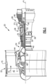
- FIG. 1 schematically illustrates a gas turbine engine 20.
- the gas turbine engine 20 is disclosed herein as a two-spool turbofan that generally incorporates a fan section 22, a compressor section 24, a combustor section 26 and a turbine section 28.
- the fan section 22 drives air along a bypass flow path B in a bypass duct defined within a nacelle 15, and also drives air along a core flow path C for compression and communication into the combustor section 26 then expansion through the turbine section 28.
- FIG. 1 schematically illustrates a gas turbine engine 20.
- the gas turbine engine 20 is disclosed herein as a two-spool turbofan that generally incorporates a fan section 22, a compressor section 24, a combustor section 26 and a turbine section 28.
- the fan section 22 drives air along a bypass flow path B in a bypass duct defined within a nacelle 15, and also drives air along a core flow path C for compression and communication into the combustor section 26 then expansion through the turbine section 28.
- FIG. 1 schematic
- the exemplary engine 20 generally includes a low speed spool 30 and a high speed spool 32 mounted for rotation about an engine central longitudinal axis A relative to an engine static structure 36 via several bearing systems 38. It should be understood that various bearing systems 38 at various locations may alternatively or additionally be provided, and the location of bearing systems 38 may be varied as appropriate to the application.
- the low speed spool 30 generally includes an inner shaft 40 that interconnects a first (or low) pressure compressor 44 and a first (or low) pressure turbine 46.
- the inner shaft 40 is connected to a fan 42 through a speed change mechanism, which in exemplary gas turbine engine 20 is illustrated as a geared architecture 48 to drive the fan 42 at a lower speed than the low speed spool 30.
- the high speed spool 32 includes an outer shaft 50 that interconnects a second (or high) pressure compressor 52 and a second (or high) pressure turbine 54.
- a combustor 56 is arranged in exemplary gas turbine 20 between the high pressure compressor 52 and the high pressure turbine 54.
- a mid-turbine frame 57 of the engine static structure 36 may be arranged generally between the high pressure turbine 54 and the low pressure turbine 46.
- the mid-turbine frame 57 further supports bearing systems 38 in the turbine section 28.
- the inner shaft 40 and the outer shaft 50 are concentric and rotate via bearing systems 38 about the engine central longitudinal axis A which is collinear
- the core airflow is compressed by the low pressure compressor 44 then the high pressure compressor 52, mixed and burned with fuel in the combustor 56, then expanded over the high pressure turbine 54 and low pressure turbine 46.
- the mid-turbine frame 57 includes airfoils 59 which are in the core airflow path C.
- the turbines 46, 54 rotationally drive the respective low speed spool 30 and high speed spool 32 in response to the expansion.
- gear system 48 may be located aft of the low pressure compressor, or aft of the combustor section 26 or even aft of turbine section 28, and fan 42 may be positioned forward or aft of the location of gear system 48.
- the engine 20 in one example is a high-bypass geared aircraft engine.
- the engine 20 bypass ratio is greater than about six, with an example embodiment being greater than about ten
- the geared architecture 48 is an epicyclic gear train, such as a planetary gear system or other gear system, with a gear reduction ratio of greater than about 2.3 and the low pressure turbine 46 has a pressure ratio that is greater than about five.
- the engine 20 bypass ratio is greater than about ten
- the fan diameter is significantly larger than that of the low pressure compressor 44
- the low pressure turbine 46 has a pressure ratio that is greater than about five.
- Low pressure turbine 46 pressure ratio is pressure measured prior to inlet of low pressure turbine 46 as related to the pressure at the outlet of the low pressure turbine 46 prior to an exhaust nozzle.
- the geared architecture 48 may be an epicycle gear train, such as a planetary gear system or other gear system, with a gear reduction ratio of greater than about 2.3:1 and less than about 5:1. It should be understood, however, that the above parameters are only exemplary of one embodiment of a geared architecture engine and that the present invention is applicable to other gas turbine engines including direct drive turbofans.
- the fan section 22 of the engine 20 is designed for a particular flight condition -- typically cruise at about 0.8 Mach and about 35,000 feet (10,668 meters).
- the flight condition of 0.8 Mach and 35,000 ft (10,668 meters), with the engine at its best fuel consumption - also known as "bucket cruise Thrust Specific Fuel Consumption ('TSFC')" - is the industry standard parameter of lbm of fuel being burned divided by lbf of thrust the engine produces at that minimum point.
- "Low fan pressure ratio” is the pressure ratio across the fan blade alone, without a Fan Exit Guide Vane (“FEGV”) system.
- the low fan pressure ratio as disclosed herein according to one non-limiting embodiment is less than about 1.45.
- the "Low corrected fan tip speed” as disclosed herein according to one non-limiting embodiment is less than about 1150 ft / second (350.5 meters/second).
- a face seal assembly 60 is illustrated in Figure 2 .
- a seal face plate or seal seat 62 is mounted for rotation about an axis A defined by an engine centerline ( Figure 1 ).
- the seal seat 62 rotates relative to a non-rotating engine component or structure 64.
- a seal housing 66 is fixed to the non-rotating structure 64.
- a seal body 68 is associated with the seal housing 66 and includes a first end surface or face 70 that faces an end surface or face 72 of the seal seat 62.
- the seal body 68 has a central bore 74 that surrounds the axis A. It should be understood that only the upper cross-section of the seal assembly 60 is shown in Figure 2 , with the lower cross-section being similarly configured to that of the upper cross-section as these components extend around the axis A.
- the seal body 68 is made from a carbon-based material as known.
- the seal body 68 includes the first end face 70, a second end face 76 axially spaced from the first end face 70, and radially inner 78 and radially outer 80 surfaces that extend between the first 70 and the second 76 end faces.
- the radially inner 78 and radially outer 80 surfaces extend parallel to each other in an axial direction along the axis A.
- the first 70 and second 76 end faces extend generally perpendicular to the radially inner 78 and radially outer 80 surfaces.
- the first end face 70 includes a protruding portion or nose 70a that extends toward the seal seat 62 to make sealing contact with the end face 72. Thus, there is direct contact between the face 72 of the seal seat 62 and the nose 70a of the carbon seal body 68.
- a seal carrier 84 is associated with the seal body 68.
- the seal carrier 84 comprises a carbon carrier for the seal body 68 that is coupled to the seal housing 66 such that the seal carrier 84 and seal body 68 comprise non-rotating components.
- the seal carrier 84 includes a radially outer wall 86 that extends in an axial direction and seats the radially outer surface 80 of the seal body 68 and a radially inwardly extending wall 88 that seats the second end face 76 of the seal body 68.
- the seal carrier 84 also includes a flange 120 that extends in an axial direction opposite from the outer wall 86. The flange 120 is positioned at a radially inward edge of the wall 88.
- the seal housing 66 includes a radially outer wall 90 extending in an axial direction and a radial wall 92 that extends radially inward from the outer wall 90.
- An open cavity 94 is formed between the outer wall 90 and radial wall 92 of the seal housing 66 and the radial wall 88 and flange 120 of the seal carrier 84.
- At least one resilient member such as a spring 96 for example, is received within this cavity 94 and is used to exert a spring force between the seal housing 66 and seal carrier 84.
- the at least one spring 96 has a first spring end 98 fixed to the seal housing 66 and a second spring end 100 fixed to the seal carrier 84.
- the seal assembly 60 includes a damper 102 that includes a contact 116 that engages the seal to dampen radial movement of the seal while accommodating axial movement of the seal.
- the damper 102 comprises at least one finger 104 extending from the seal housing 66 in an axial direction to a distal end 106 that extends in a radial inward direction toward the seal carrier 84.
- the finger 104 has an axially extending elongated body 108 having the distal end 106 at one end and a connecting portion 110 at an opposite end.
- the connecting portion 110 extends in a radially inward direction from the elongated body 108 to connect to a radially outer surface 112 of the outer wall 90 of the seal housing 66.
- the elongated body 108 of the finger 104 includes a narrowing neck portion 114 to adjust radial stiffness.
- the narrowing neck portion 114 comprises a reduced diameter portion compared to diameters at portions of the elongated body 108 at the distal end 106 and/or connecting portion 110.
- This reduced diameter portion or narrowing neck portion 114 basically comprises a pivoting area that allows the distal end 106 to move up and down in a radial direction to accommodate radial movement of the seal carrier 84 and seal body 68.
- the distal end 106 is configured such that the finger 104 is always in contact with the seal carrier 84 during engine operation, i.e. there is never a radial gap between the contact 116 at the distal end 106 and the seal carrier 84.
- the distal end 106 includes the contact 116 that directly engages a radially outer surface 118 of the seal carrier 84.
- the contact 116 comprises at least one bearing ball that maintains radial contact with the seal carrier while simultaneoulsy allowing axial movement of the seal carrier 84 relative to the seal housing 66 and seal seat 62.
- the bearing ball rotates within the distal end 106 of the finger 104 to accommodate the axial movement.
- the bearing ball comprises a full sphere that is installed within a socket formed in the distal end 106 of the finger 104.
- the ball is fully retained within the socket with approximately 1 ⁇ 4 of the ball protruding to contact the carbon seal carrier 84.
- the bearing ball is made from a ceramic material such as silicon nitride or other similar materials, for example.
- the at least one finger 104 comprises a plurality of fingers 104.
- Figure 3 shows a configuration where there are three fingers 104 with dampers 102.
- the fingers 104 are equally spaced apart from each other in a circumferential direction about the axis A.
- the subject invention provides one or more fingers that contact the carbon seal carrier in a radial direction via bearing balls.
- the fingers are attached to the seal housing and are configured to be flexible enough to account for small amounts of radial travel while maintaining contact.
- the distal end(s) of the finger(s) include the bearing ball(s), which are in direct contact with the carbon seal carrier. This allows axial movement of the seal without creating extra drag.
- the seal includes a spring and is compressed/elongated during operation so the bearing ball(s) will not impede the natural motion of the seal.
- the subject invention provides a mechanical solution that is much simpler and compact as compared to prior air or oil film dampers. Further, the mechanical solution is capable of limiting radial movement of the seal without adversely impacting axial movement of the seal.
Landscapes
- Engineering & Computer Science (AREA)
- General Engineering & Computer Science (AREA)
- Mechanical Engineering (AREA)
- Chemical & Material Sciences (AREA)
- Combustion & Propulsion (AREA)
- Structures Of Non-Positive Displacement Pumps (AREA)
- Mechanical Sealing (AREA)
Description
- This invention relates to a gas turbine engine that includes a component comprising a face seal with a damper.
- Gas turbine engines are known and typically include a fan delivering air into a bypass duct as bypass air and into a compressor as core air. The air is compressed and delivered into a combustor section where it is mixed with fuel and ignited. Products of the combustion pass downstream over turbine rotors, driving them to rotate.
- In one known type of gas turbine engine, there are at least two turbine rotors, each driving a compressor rotor. One of the two rotors rotates at higher speeds relative to a lower speed rotor. In one example, a seal for an engine bearing compartment is installed within a stationary seal carrier. The seal has an end face that contacts a rotating seal face plate or seat. The face plate is mounted for rotation with a rotor shaft that connects a turbine rotor to a compressor rotor.
- The seal should be able to accommodate axial and radial movement, however, excessive movement can be potentially damaging. For example, the seal has a vibratory mode that results in a lower frequency precession, which can cause damage to the seal as a result of an impact between the stationary seal and the rotating seat. It has been proposed to control movement using an air or oil film damper but these systems can be overly complicated and expensive.
- An example of such a system is disclosed in
EP 3009612 A1 in which a noncontacting dynamic seal having wave springs is disclosed. The seal has a shoe coupled to an outer ring by an inner and an outer beam. A wave spring is located between the inner and outer beams, between the shoe and the inner beam, or between the outer beam and the outer ring. The wave spring may damp vibrations in the inner and outer beams. -
EP 2740975 A1 discloses a rotary air-riding seal between a first structure and an adjacent second structure. At least one of the structures is rotatable relative to the other about an axis of rotation. A seal between the structures includes first and second seal members defining respective seal surfaces which are facing each other. The seals are mounted on the first and second structures in a fashion allowing axial oscillation of one of the seal members and to resiliently bias the seal member towards each other. -
EP 3012413 A1 discloses a seal support structure for a circumferential. The seal support structure includes an engine support structure, a seal support, and a shoulder joining the engine support and seal support. The shoulder offsets the engine support from the seal support, and the shoulder and the seal support structure are configured to dampen vibration for the circumferential seal. The seal support structure employs a dampening ring that interoperates with the seal support structure to dampen radial vibration of seal system. - In accordance with a first aspect of the disclosure, a gas turbine engine component comprising: a static component comprising a seal housing fixed to a non-rotating engine structure; a seal body associated with the static component, the seal body having an end face configured to face a rotating seal seat; a seal carrier fixed to the seal body; characterised in that the component further comprises at least one spring acting between the seal housing and the seal body to accommodate axial movement of the seal body relative to the rotating seal seat, a damper positioned radially outward of the seal body, wherein the damper comprises a plurality of fingers, each finger extending from the seal housing in an axial direction to a distal end that extends in a radial inward direction toward the seal carrier, and wherein each finger includes a contact that engages the seal body to dampen radial movement of the seal body while accommodating axial movement of the seal body.
- In an embodiment according to the previous embodiment, the static component comprises a seal housing fixed to a non-rotating engine structure.
- In another embodiment according to any of the previous embodiments, the component includes a seal carrier fixed to the seal body.
- In another embodiment according to any of the previous embodiments, the at least one spring has a first spring end fixed to the seal housing and a second spring end fixed to the seal carrier.
- In another embodiment according to any of the previous embodiments, the at least one finger includes a narrowing neck portion to adjust radial stiffness.
- In another embodiment according to any of the previous embodiments, the distal end includes the contact that directly engages a radially outer surface of the seal carrier.
- In another embodiment according to any of the previous embodiments, the contact comprises at least one bearing ball that maintains radial contact with the seal carrier while allowing axial movement of the seal carrier relative to the seal housing and seal seat.
- In another embodiment according to any of the previous embodiments, the seal body comprises a carbon face seal.
- In accordance with a second aspect of the disclosure, a gas turbine engine comprising: at least one rotor shaft that interconnects a compressor and a turbine for rotation about an engine center axis; and a carbon face seal assembly including a gas turbine engine component of the first aspect of the disclosure, a seal seat mounted for rotation with the at least one rotor shaft, and the seal body is positioned axially between the seal housing and the seal seat.
- In another embodiment according to any of the previous embodiments, the distal end includes the contact, which comprises at least one bearing ball that maintains radial contact with the seal body while allowing axial movement of the seal body relative to the seal housing and seal seat.
- In another embodiment according to any of the previous embodiments, the seal body includes a first end face, a second end face axially spaced from the first end face, and radially inner and radially outer surfaces that extend between the first and the second end faces, and including a seal carrier fixed to the seal body at least at the radially outer surface, and wherein the distal end of the at least one finger extends in a radial inward direction to directly engage a radially outer surface of the seal carrier.
- In another embodiment according to any of the previous embodiments, the engine further includes at least one spring acting between the seal housing and the seal body to accommodate axial movement of the seal body relative to the seal seat, and wherein the at least one spring has a first spring end fixed to the seal housing and a second spring end fixed to the seal carrier.
- In another embodiment according to any of the previous embodiments, the at least one finger includes a narrowing neck portion to adjust radial stiffness.
- In accordance with a third aspect of the disclosure, a method of operating a gas turbine comprising the steps of: driving at least one shaft with a turbine rotor to drive a compressor; holding a seal body in a non-rotating relationship relative to a rotating seal seat coupled to the at least one shaft in which the seal body has an end face configured to face the seal seat and which is associated with a static component comprising a seal housing fixed to a non-rotating engine structure; fixing a seal carrier to the seal body; and damping radial movement of the seal body with a damper positioned radially outward of the seal body while accommodating axial movement of the seal body relative to the rotating seal seat, wherein the damper comprises a plurality of fingers, each finger extending from the seal housing in an axial direction to a distal end that extends in a radial inward direction toward the seal carrier, and wherein each finger includes a contact that engages the seal body to dampen radial movement of the seal body while accommodating axial movement of the seal body.
- In another embodiment according to any of the previous embodiments, the method includes providing a seal carrier fixed to the seal body and providing the distal end with at least one bearing ball, and further includes connecting a first spring end of at least one spring to a non-rotating engine structure, connecting a second spring end of the at least one spring to the seal carrier such that the at least one spring accommodates axial movement of the seal body relative to the rotating seal seat, and extending the distal end of each finger in a radial inward direction to directly engage a radially outer surface of the seal carrier to dampen radial movement of the seal body.
- These and other features may be best understood from the following drawings and specification.
-
-
Figure 1 schematically shows a gas turbine engine. -
Figure 2 shows a schematic illustration of a seal assembly as used in the gas turbine engine ofFigure 1 . -
Figure 3 shows a schematic example of the seal assembly including a plurality of damping contacts. -
Figure 1 schematically illustrates agas turbine engine 20. Thegas turbine engine 20 is disclosed herein as a two-spool turbofan that generally incorporates afan section 22, acompressor section 24, a combustor section 26 and aturbine section 28. Thefan section 22 drives air along a bypass flow path B in a bypass duct defined within anacelle 15, and also drives air along a core flow path C for compression and communication into the combustor section 26 then expansion through theturbine section 28. Although depicted as a two-spool turbofan gas turbine engine in the disclosed non-limiting embodiment, it should be understood that the concepts described herein are not limited to use with two-spool turbofans as the teachings may be applied to other types of turbine engines including three-spool architectures. - The
exemplary engine 20 generally includes alow speed spool 30 and ahigh speed spool 32 mounted for rotation about an engine central longitudinal axis A relative to an enginestatic structure 36 viaseveral bearing systems 38. It should be understood thatvarious bearing systems 38 at various locations may alternatively or additionally be provided, and the location ofbearing systems 38 may be varied as appropriate to the application. - The
low speed spool 30 generally includes aninner shaft 40 that interconnects a first (or low) pressure compressor 44 and a first (or low)pressure turbine 46. Theinner shaft 40 is connected to afan 42 through a speed change mechanism, which in exemplarygas turbine engine 20 is illustrated as a gearedarchitecture 48 to drive thefan 42 at a lower speed than thelow speed spool 30. Thehigh speed spool 32 includes anouter shaft 50 that interconnects a second (or high)pressure compressor 52 and a second (or high)pressure turbine 54. Acombustor 56 is arranged inexemplary gas turbine 20 between thehigh pressure compressor 52 and thehigh pressure turbine 54. Amid-turbine frame 57 of the enginestatic structure 36 may be arranged generally between thehigh pressure turbine 54 and thelow pressure turbine 46. Themid-turbine frame 57 further supports bearingsystems 38 in theturbine section 28. Theinner shaft 40 and theouter shaft 50 are concentric and rotate viabearing systems 38 about the engine central longitudinal axis A which is collinear with their longitudinal axes. - The core airflow is compressed by the low pressure compressor 44 then the
high pressure compressor 52, mixed and burned with fuel in thecombustor 56, then expanded over thehigh pressure turbine 54 andlow pressure turbine 46. Themid-turbine frame 57 includesairfoils 59 which are in the core airflow path C. Theturbines low speed spool 30 andhigh speed spool 32 in response to the expansion. It will be appreciated that each of the positions of thefan section 22,compressor section 24, combustor section 26,turbine section 28, and fandrive gear system 48 may be varied. For example,gear system 48 may be located aft of the low pressure compressor, or aft of the combustor section 26 or even aft ofturbine section 28, andfan 42 may be positioned forward or aft of the location ofgear system 48. - The
engine 20 in one example is a high-bypass geared aircraft engine. In a further example, theengine 20 bypass ratio is greater than about six, with an example embodiment being greater than about ten, the gearedarchitecture 48 is an epicyclic gear train, such as a planetary gear system or other gear system, with a gear reduction ratio of greater than about 2.3 and thelow pressure turbine 46 has a pressure ratio that is greater than about five. In one disclosed embodiment, theengine 20 bypass ratio is greater than about ten, the fan diameter is significantly larger than that of the low pressure compressor 44, and thelow pressure turbine 46 has a pressure ratio that is greater than about five.Low pressure turbine 46 pressure ratio is pressure measured prior to inlet oflow pressure turbine 46 as related to the pressure at the outlet of thelow pressure turbine 46 prior to an exhaust nozzle. The gearedarchitecture 48 may be an epicycle gear train, such as a planetary gear system or other gear system, with a gear reduction ratio of greater than about 2.3:1 and less than about 5:1. It should be understood, however, that the above parameters are only exemplary of one embodiment of a geared architecture engine and that the present invention is applicable to other gas turbine engines including direct drive turbofans. - A significant amount of thrust is provided by the bypass flow B due to the high bypass ratio. The
fan section 22 of theengine 20 is designed for a particular flight condition -- typically cruise at about 0.8 Mach and about 35,000 feet (10,668 meters). The flight condition of 0.8 Mach and 35,000 ft (10,668 meters), with the engine at its best fuel consumption - also known as "bucket cruise Thrust Specific Fuel Consumption ('TSFC')" - is the industry standard parameter of lbm of fuel being burned divided by lbf of thrust the engine produces at that minimum point. "Low fan pressure ratio" is the pressure ratio across the fan blade alone, without a Fan Exit Guide Vane ("FEGV") system. The low fan pressure ratio as disclosed herein according to one non-limiting embodiment is less than about 1.45. "Low corrected fan tip speed" is the actual fan tip speed in ft/sec divided by an industry standard temperature correction of [(Tram °R) / (518.7 °R)]0.5 (where °R = K x 9/5). The "Low corrected fan tip speed" as disclosed herein according to one non-limiting embodiment is less than about 1150 ft / second (350.5 meters/second). - A
face seal assembly 60 is illustrated inFigure 2 . A seal face plate or sealseat 62 is mounted for rotation about an axis A defined by an engine centerline (Figure 1 ). Theseal seat 62 rotates relative to a non-rotating engine component orstructure 64. Aseal housing 66 is fixed to thenon-rotating structure 64. Aseal body 68 is associated with theseal housing 66 and includes a first end surface or face 70 that faces an end surface or face 72 of theseal seat 62. Theseal body 68 has acentral bore 74 that surrounds the axis A. It should be understood that only the upper cross-section of theseal assembly 60 is shown inFigure 2 , with the lower cross-section being similarly configured to that of the upper cross-section as these components extend around the axis A. - The
seal body 68 is made from a carbon-based material as known. Theseal body 68 includes thefirst end face 70, a second end face 76 axially spaced from thefirst end face 70, and radially inner 78 and radially outer 80 surfaces that extend between the first 70 and the second 76 end faces. The radially inner 78 and radially outer 80 surfaces extend parallel to each other in an axial direction along the axis A. The first 70 and second 76 end faces extend generally perpendicular to the radially inner 78 and radially outer 80 surfaces. Thefirst end face 70 includes a protruding portion ornose 70a that extends toward theseal seat 62 to make sealing contact with theend face 72. Thus, there is direct contact between theface 72 of theseal seat 62 and thenose 70a of thecarbon seal body 68. - A
seal carrier 84 is associated with theseal body 68. Theseal carrier 84 comprises a carbon carrier for theseal body 68 that is coupled to theseal housing 66 such that theseal carrier 84 and sealbody 68 comprise non-rotating components. In one example, theseal carrier 84 includes a radiallyouter wall 86 that extends in an axial direction and seats the radiallyouter surface 80 of theseal body 68 and a radially inwardly extending wall 88 that seats the second end face 76 of theseal body 68. Theseal carrier 84 also includes aflange 120 that extends in an axial direction opposite from theouter wall 86. Theflange 120 is positioned at a radially inward edge of the wall 88. - In one example, the
seal housing 66 includes a radiallyouter wall 90 extending in an axial direction and aradial wall 92 that extends radially inward from theouter wall 90. Anopen cavity 94 is formed between theouter wall 90 andradial wall 92 of theseal housing 66 and the radial wall 88 andflange 120 of theseal carrier 84. At least one resilient member, such as aspring 96 for example, is received within thiscavity 94 and is used to exert a spring force between theseal housing 66 andseal carrier 84. The at least onespring 96 has afirst spring end 98 fixed to theseal housing 66 and asecond spring end 100 fixed to theseal carrier 84. - The
seal assembly 60 includes adamper 102 that includes acontact 116 that engages the seal to dampen radial movement of the seal while accommodating axial movement of the seal. In one example, thedamper 102 comprises at least onefinger 104 extending from theseal housing 66 in an axial direction to adistal end 106 that extends in a radial inward direction toward theseal carrier 84. Thefinger 104 has an axially extendingelongated body 108 having thedistal end 106 at one end and a connecting portion 110 at an opposite end. In one example, the connecting portion 110 extends in a radially inward direction from theelongated body 108 to connect to a radiallyouter surface 112 of theouter wall 90 of theseal housing 66. - In one example, the
elongated body 108 of thefinger 104 includes a narrowing neck portion 114 to adjust radial stiffness. The narrowing neck portion 114 comprises a reduced diameter portion compared to diameters at portions of theelongated body 108 at thedistal end 106 and/or connecting portion 110. This reduced diameter portion or narrowing neck portion 114 basically comprises a pivoting area that allows thedistal end 106 to move up and down in a radial direction to accommodate radial movement of theseal carrier 84 and sealbody 68. Thedistal end 106 is configured such that thefinger 104 is always in contact with theseal carrier 84 during engine operation, i.e. there is never a radial gap between thecontact 116 at thedistal end 106 and theseal carrier 84. As such, thedistal end 106 includes thecontact 116 that directly engages a radiallyouter surface 118 of theseal carrier 84. - In one example, the
contact 116 comprises at least one bearing ball that maintains radial contact with the seal carrier while simultaneoulsy allowing axial movement of theseal carrier 84 relative to theseal housing 66 and sealseat 62. The bearing ball rotates within thedistal end 106 of thefinger 104 to accommodate the axial movement. In one example, the bearing ball comprises a full sphere that is installed within a socket formed in thedistal end 106 of thefinger 104. In one example, the ball is fully retained within the socket with approximately ¼ of the ball protruding to contact thecarbon seal carrier 84. The bearing ball is made from a ceramic material such as silicon nitride or other similar materials, for example. - In one example, the at least one
finger 104 comprises a plurality offingers 104.Figure 3 shows a configuration where there are threefingers 104 withdampers 102. Thefingers 104 are equally spaced apart from each other in a circumferential direction about the axis A. - The subject invention provides one or more fingers that contact the carbon seal carrier in a radial direction via bearing balls. The fingers are attached to the seal housing and are configured to be flexible enough to account for small amounts of radial travel while maintaining contact. The distal end(s) of the finger(s) include the bearing ball(s), which are in direct contact with the carbon seal carrier. This allows axial movement of the seal without creating extra drag. The seal includes a spring and is compressed/elongated during operation so the bearing ball(s) will not impede the natural motion of the seal.
- The subject invention provides a mechanical solution that is much simpler and compact as compared to prior air or oil film dampers. Further, the mechanical solution is capable of limiting radial movement of the seal without adversely impacting axial movement of the seal.
- Although an embodiment of this invention has been disclosed, a worker of ordinary skill in this art would recognize that certain modifications would come within the scope of this disclosure. For that reason, the following claims should be studied to determine the true scope and content of this disclosure.
Claims (15)
- A gas turbine engine component comprising:a static component comprising a seal housing (66) fixed to a non-rotating engine structure (64);a seal body (68) associated with the static component, the seal body (68) having an end face (70) configured to face a rotating seal seat (62);a seal carrier (84) fixed to the seal body (68); characterised in that the component further comprisesat least one spring (96) acting between the seal housing (66) and the seal carrier (84) to accommodate axial movement of the seal body (68) relative to the rotating seal seat (62) and a damper (102) positioned radially outward of the seal body (68), wherein the damper (102) comprises a plurality of fingers (104), each finger (104) extending from the seal housing (66) in an axial direction to a distal end (106) that extends in a radial inward direction toward the seal carrier (84), and wherein each finger (104) includes a contact (116) that engages the seal body (68) to dampen radial movement of the seal body (68) while accommodating axial movement of the seal body (68).
- The gas turbine engine component as set forth in claim 1, wherein the seal body (68) includes the end face (70), a second end face (76) axially spaced from the first end face (70), and radially inner and radially outer surfaces (78, 80) that extend between the first and the second end faces (70, 76), and wherein the seal carrier (84) is fixed to the seal body (68) at least at the radially outer surface (80), and the distal end (106) of the plurality of fingers (104) extends in the radial inward direction to directly engage a radially outer surface (118) of the seal carrier (84).
- The gas turbine engine component as set forth in claim 2, wherein the at least one spring (96) has a first spring end (98) fixed to the seal housing (66) and a second spring end (100) fixed to the seal carrier (84).
- The gas turbine engine component as set forth in any preceding claim, wherein each distal end (106) includes the contact (116) that directly engages a radially outer surface (118) of the seal carrier (84) and/or the plurality of fingers (104) include a narrowing neck portion (114) to adjust radial stiffness.
- The gas turbine engine component as set forth in any of claims 2 to 4, wherein the contact (116) comprises at least one bearing ball that maintains radial contact with the seal carrier (84) while allowing axial movement of the seal carrier (84) relative to the seal housing (66) and seal seat (62).
- The gas turbine engine component as set forth in any preceding claim, wherein the seal body (68) comprises a carbon face seal.
- A gas turbine engine (20) comprising:at least one rotor shaft (40, 50) that interconnects a compressor (44, 52) and a turbine (46, 54) for rotation about an engine center axis (A); anda carbon face seal assembly (60) including a gas turbine engine component as set forth in claim 1, a seal seat (62) mounted for rotation with the at least one rotor shaft (40, 50), and the seal body (68) is positioned axially between the seal housing (66) and the seal seat (62).
- The gas turbine engine as set forth in claim 7, wherein the distal end (106) includes the contact (116) which comprises at least one bearing ball that maintains radial contact with the seal body (68) while allowing axial movement of the seal body (68) relative to the seal housing (66) and seal seat (62).
- The gas turbine engine as set forth in claim 8, wherein the seal body (68) includes a first end face (70), a second end face (76) axially spaced from the first end face (70), and radially inner and radially outer surfaces (78, 80) that extend between the first and the second end faces (70, 76), and wherein the seal carrier (84) is fixed to the seal body (68) at least at the radially outer surface (80), and the distal end (106) of each finger (104) extends in a radial inward direction to directly engage a radially outer surface (118) of the seal carrier (84), and, optionally, the at least one spring (96) has a first spring end (98) fixed to the seal housing (66) and a second spring end (100) fixed to the seal carrier (84).
- The gas turbine engine as set forth in claim 8 or 9, wherein each finger (104) includes a narrowing neck portion (114) to adjust radial stiffness.
- A method of operating a gas turbine comprising the steps of:driving at least one shaft (40, 50) with a turbine rotor to drive a compressor (44, 52);holding a seal body (68) in a non-rotating relationship relative to a rotating seal seat (62) coupled to the at least one shaft (40, 50) in which the seal body (68) has an end face (70) configured to face the seal seat (62) and which is associated with a static component comprising a seal housing (66) fixed to a non-rotating engine structure (64);fixing a seal carrier (84) to the seal body (68);at least one spring (96) acting between the seal housing (66) and the seal carrier (84) to accommodate axial movement of the seal body (68) relative to the rotating seal seat (62); anddamping radial movement of the seal body (68) with a damper (102) positioned radially outward of the seal body (68) while accommodating axial movement of the seal body (68) relative to the rotating seal seat (62), wherein the damper (102) comprises a plurality of fingers (104), each finger (104) extending from the seal housing (66) in an axial direction to a distal end (106) that extends in a radial inward direction toward the seal carrier (84), and wherein each finger (104) includes a contact (116) that engages the seal body (68) to dampen radial movement of the seal body (68) while accommodating axial movement of the seal body (68).
- The method as set forth in claim 11, wherein the distal end (106) maintains contact with a radially outer surface (80) of the seal body (68) for radially damping while allowing axial movement of the seal body (68) relative to the rotating seal seat (62).
- The method as set forth in claim 12, including providing the distal end (106) with at least one bearing ball, and includingconnecting a first spring end (98) of the at least one spring (96) to a non-rotating engine structure (64),connecting a second spring end (100) of the at least one spring (96) to the seal carrier (84) such that the at least one spring (96) accommodates axial movement of the seal body (68) relative to the rotating seal seat (62), andextending the distal end (106) of each finger (104) in a radial inward direction to directly engage a radially outer surface (118) of the seal carrier (84) to dampen radial movement of the seal body (68).
- The method as set forth in claim 11, including rotating the contact (116) within the damper (102) to accommodate the axial movement, and pivoting the damper (102) via a pivoting area (114) to allow the damper (102) to move up and down in a radial direction to accommodate the radial movement, and wherein the contact (116) comprises a bearing ball and the pivoting area (114) is part of a narrowing neck portion.
- The gas turbine engine component as set forth in claim 1 or gas turbine engine as set forth in claim 7, wherein the contact (116) rotates within the damper (102) to accommodate the axial movement, and wherein the damper (102) includes a pivoting area (114) that allows the damper (102) to move up and down in a radial direction to accommodate the radial movement, and wherein the contact (116) comprises a bearing ball and the pivoting area (114) is part of a narrowing neck portion.
Applications Claiming Priority (1)
| Application Number | Priority Date | Filing Date | Title |
|---|---|---|---|
| US16/267,584 US11035253B2 (en) | 2019-02-05 | 2019-02-05 | Face seal with damper |
Publications (2)
| Publication Number | Publication Date |
|---|---|
| EP3693555A1 EP3693555A1 (en) | 2020-08-12 |
| EP3693555B1 true EP3693555B1 (en) | 2024-09-18 |
Family
ID=69500622
Family Applications (1)
| Application Number | Title | Priority Date | Filing Date |
|---|---|---|---|
| EP20155676.8A Active EP3693555B1 (en) | 2019-02-05 | 2020-02-05 | Face seal with damper |
Country Status (2)
| Country | Link |
|---|---|
| US (1) | US11035253B2 (en) |
| EP (1) | EP3693555B1 (en) |
Families Citing this family (6)
| Publication number | Priority date | Publication date | Assignee | Title |
|---|---|---|---|---|
| CN116696491B (en) * | 2022-03-03 | 2026-04-03 | 通用电气公司 | Sealing components and related methods for turbine engines |
| US11905837B2 (en) * | 2022-03-23 | 2024-02-20 | General Electric Company | Sealing system including a seal assembly between components |
| US12241379B2 (en) | 2022-08-03 | 2025-03-04 | General Electric Company | Cooling system for seal assemblies |
| CN119177884A (en) * | 2023-06-23 | 2024-12-24 | 通用电气公司 | Face seal robust to housing vibration |
| US12480418B1 (en) * | 2024-07-15 | 2025-11-25 | Rtx Corporation | Seal assembly for gas turbine engines |
| US12410724B1 (en) | 2024-07-31 | 2025-09-09 | General Electric Company | Gas turbine engine with inertially damped seals |
Family Cites Families (50)
| Publication number | Priority date | Publication date | Assignee | Title |
|---|---|---|---|---|
| US3372939A (en) | 1965-10-22 | 1968-03-12 | Kopper Company Inc | Rotary face seal with vibration damping means |
| US3776560A (en) * | 1971-03-04 | 1973-12-04 | Borg Warner | Bellows type fluid seal |
| US3759533A (en) | 1971-04-12 | 1973-09-18 | W Neely | Sealing means for rotating shaft |
| US3915521A (en) | 1974-09-30 | 1975-10-28 | United Technologies Corp | Lubricated radial bearing assembly |
| JPS5351965Y2 (en) | 1975-03-27 | 1978-12-12 | ||
| US4026564A (en) | 1975-12-23 | 1977-05-31 | Atomic Energy Of Canada Limited | Rotary shaft face seal |
| US4407512A (en) | 1976-01-02 | 1983-10-04 | John Crane-Houdaille, Inc. | High pressure rotary mechanical seal |
| US4142731A (en) | 1977-05-13 | 1979-03-06 | Tsentralny Nauchno-Issledovatelsky Avtomobilny I Avtomotorny Institut Nami | End-type seal |
| US4192633A (en) * | 1977-12-28 | 1980-03-11 | General Electric Company | Counterweighted blade damper |
| US4406459A (en) | 1982-06-18 | 1983-09-27 | United Technologies Corporation | Oil weepage return for carbon seal plates |
| US4453722A (en) * | 1982-12-20 | 1984-06-12 | United Technologies Corporation | Seal means |
| US4477088A (en) * | 1982-12-20 | 1984-10-16 | United Technologies Corporation | Face seal means with back-up seal |
| US4527910A (en) * | 1984-04-05 | 1985-07-09 | The United States Of America As Represented By The Administrator Of The National Aeronautics And Space Administration | Dual clearance squeeze film damper |
| US5088890A (en) | 1989-12-11 | 1992-02-18 | Sundstrand Corporation | Seal construction for use in a turbine engine |
| US5211536A (en) * | 1991-05-13 | 1993-05-18 | General Electric Company | Boltless turbine nozzle/stationary seal mounting |
| DE4138405C1 (en) * | 1991-11-22 | 1993-02-25 | Fa. Carl Freudenberg, 6940 Weinheim, De | |
| US5501471A (en) | 1992-06-11 | 1996-03-26 | Nippon Pillar Packing Co., Ltd. | Mechanical seal with blade-like sealing end |
| US5263312A (en) * | 1992-07-21 | 1993-11-23 | General Electric Company | Tube fitting for a gas turbine engine |
| JP3555683B2 (en) | 1992-08-11 | 2004-08-18 | ユナイテッド・テクノロジーズ・コーポレイション | Seal assembly for rotating machine |
| US5415526A (en) * | 1993-11-19 | 1995-05-16 | Mercadante; Anthony J. | Coolable rotor assembly |
| US5490679A (en) | 1993-12-20 | 1996-02-13 | John Crane Inc. | Seal ring design |
| GB2285101A (en) | 1993-12-23 | 1995-06-28 | Crane John Uk Ltd | Seal for use with liquids |
| US6131914A (en) | 1996-08-30 | 2000-10-17 | United Technologies Corporation | Gas turbine engine bearing compartment seal |
| US6565095B2 (en) * | 2001-07-12 | 2003-05-20 | Honeywell International, Inc. | Face seal with internal drain |
| US6758477B2 (en) | 2002-03-26 | 2004-07-06 | General Electric Company | Aspirating face seal with axially biasing one piece annular spring |
| US6676369B2 (en) | 2002-03-26 | 2004-01-13 | General Electric Company | Aspirating face seal with axially extending seal teeth |
| GB0312185D0 (en) * | 2003-05-28 | 2003-07-02 | Aesseal Plc | A seal damper |
| US20050206088A1 (en) | 2004-03-16 | 2005-09-22 | Anderson James H | Bearing seal with backup device |
| US7225626B2 (en) | 2004-08-16 | 2007-06-05 | Honeywell International, Inc. | Thermal management of a gas turbine bearing compartment utilizing separate lubrication and cooling circuits |
| US7410341B2 (en) | 2005-06-22 | 2008-08-12 | Honeywell International, Inc. | Internally-cooled seal housing for turbine engine |
| US7837199B2 (en) * | 2005-11-03 | 2010-11-23 | United Technologies Corporation | Shrouded face seal and components thereof |
| US7754350B2 (en) * | 2006-05-02 | 2010-07-13 | United Technologies Corporation | Wear-resistant coating |
| US8215894B2 (en) * | 2007-11-13 | 2012-07-10 | United Technologies Corporation | Dual configuration seal assembly for a rotational assembly |
| US7946590B2 (en) | 2008-01-17 | 2011-05-24 | United Technologies Corporation | Face seal for gas turbine engine |
| EP2615325B1 (en) * | 2012-01-16 | 2019-10-02 | Fraunhofer-Gesellschaft zur Förderung der angewandten Forschung e.V. | Active bearing |
| FR2993024B1 (en) | 2012-07-06 | 2014-08-08 | Snecma | TURBOMACHINE BEARING SEAL SEAL DEVICE WITH TWO ELASTIC JOINTS |
| US8919779B2 (en) * | 2012-12-06 | 2014-12-30 | Rolls-Royce Plc | Air-riding seal |
| US10233762B2 (en) * | 2013-02-27 | 2019-03-19 | United Technologies Corporation | Cooled seal assembly for arranging between a stator and a rotor |
| US10801348B2 (en) | 2014-10-14 | 2020-10-13 | Raytheon Technologies Corporation | Non-contacting dynamic seal |
| US9988921B2 (en) | 2014-10-17 | 2018-06-05 | United Technologies Corporation | Circumferential seal with seal dampening elements |
| US9879780B2 (en) | 2014-10-24 | 2018-01-30 | United Technologies Corporation | Sliding seal |
| US10443450B2 (en) | 2014-10-24 | 2019-10-15 | United Technologies Corporation | Seal support structure for a circumferential seal of a gas turbine engine |
| GB201514651D0 (en) * | 2015-08-18 | 2015-09-30 | Rolls Royce Plc | Sealing arrangements |
| EP3156611A1 (en) * | 2015-10-12 | 2017-04-19 | Siemens Aktiengesellschaft | Sealing part for a gas turbine and method for manufacturing such a sealing part |
| US10563530B2 (en) * | 2015-10-12 | 2020-02-18 | General Electric Company | Intershaft seal with dual opposing carbon seal rings |
| GB201612099D0 (en) * | 2016-07-12 | 2016-08-24 | Rolls Royce Deutschland Ltd & Co Kg | A geared gas turbine engine |
| GB201706179D0 (en) * | 2017-04-19 | 2017-05-31 | Rolls Royce Plc | Bearing arrangement |
| US10385713B2 (en) * | 2017-08-24 | 2019-08-20 | United Technologies Corporation | Seal assembly for gas turbine engines |
| US10619741B2 (en) * | 2017-09-12 | 2020-04-14 | United Technologies Corporation | Contacting dry face seal with tapered carbon nose |
| US10655487B2 (en) * | 2018-02-15 | 2020-05-19 | Raytheon Technologies Corporation | Pressure balanced secondary seal |
-
2019
- 2019-02-05 US US16/267,584 patent/US11035253B2/en active Active
-
2020
- 2020-02-05 EP EP20155676.8A patent/EP3693555B1/en active Active
Also Published As
| Publication number | Publication date |
|---|---|
| US11035253B2 (en) | 2021-06-15 |
| EP3693555A1 (en) | 2020-08-12 |
| US20200248588A1 (en) | 2020-08-06 |
Similar Documents
| Publication | Publication Date | Title |
|---|---|---|
| EP3693555B1 (en) | Face seal with damper | |
| US10066496B2 (en) | Gas turbine engine and seal assembly therefore | |
| US10240529B2 (en) | Gas turbine engine aft bearing arrangement | |
| US10370991B2 (en) | Gas turbine engine and seal assembly therefore | |
| US20150285152A1 (en) | Gas turbine engine and seal assembly therefore | |
| EP3677817B1 (en) | Hydrostatic seal with extended housing | |
| EP3680521B1 (en) | Hydrostatic seal with aft tooth | |
| US11199102B2 (en) | Hydrostatic seal with increased design space | |
| EP3453838B1 (en) | Contacting dry face seal with tapered carbon nose | |
| EP3789589B1 (en) | Hydrostatic seal | |
| EP3739241B1 (en) | Brush secondary seal for cantilevered hydrostatic advanced low leakage seal | |
| EP3088676B1 (en) | Gas turbine engine damping device | |
| EP3428408B1 (en) | Gas turbine engine variable vane end wall insert | |
| EP3835606B1 (en) | Curved beam centering spring for a thrust bearing | |
| EP3816472B1 (en) | Axially rigid curved beam with squeeze damper | |
| US11371375B2 (en) | Heatshield with damper member | |
| EP4006310B1 (en) | Face seal arrangement with reduced balance ratio |
Legal Events
| Date | Code | Title | Description |
|---|---|---|---|
| PUAI | Public reference made under article 153(3) epc to a published international application that has entered the european phase |
Free format text: ORIGINAL CODE: 0009012 |
|
| STAA | Information on the status of an ep patent application or granted ep patent |
Free format text: STATUS: THE APPLICATION HAS BEEN PUBLISHED |
|
| AK | Designated contracting states |
Kind code of ref document: A1 Designated state(s): AL AT BE BG CH CY CZ DE DK EE ES FI FR GB GR HR HU IE IS IT LI LT LU LV MC MK MT NL NO PL PT RO RS SE SI SK SM TR |
|
| AX | Request for extension of the european patent |
Extension state: BA ME |
|
| STAA | Information on the status of an ep patent application or granted ep patent |
Free format text: STATUS: REQUEST FOR EXAMINATION WAS MADE |
|
| 17P | Request for examination filed |
Effective date: 20210212 |
|
| RAP1 | Party data changed (applicant data changed or rights of an application transferred) |
Owner name: RAYTHEON TECHNOLOGIES CORPORATION |
|
| RBV | Designated contracting states (corrected) |
Designated state(s): AL AT BE BG CH CY CZ DE DK EE ES FI FR GB GR HR HU IE IS IT LI LT LU LV MC MK MT NL NO PL PT RO RS SE SI SK SM TR |
|
| STAA | Information on the status of an ep patent application or granted ep patent |
Free format text: STATUS: EXAMINATION IS IN PROGRESS |
|
| 17Q | First examination report despatched |
Effective date: 20210511 |
|
| RAP3 | Party data changed (applicant data changed or rights of an application transferred) |
Owner name: RTX CORPORATION |
|
| GRAP | Despatch of communication of intention to grant a patent |
Free format text: ORIGINAL CODE: EPIDOSNIGR1 |
|
| STAA | Information on the status of an ep patent application or granted ep patent |
Free format text: STATUS: GRANT OF PATENT IS INTENDED |
|
| INTG | Intention to grant announced |
Effective date: 20240209 |
|
| GRAJ | Information related to disapproval of communication of intention to grant by the applicant or resumption of examination proceedings by the epo deleted |
Free format text: ORIGINAL CODE: EPIDOSDIGR1 |
|
| STAA | Information on the status of an ep patent application or granted ep patent |
Free format text: STATUS: EXAMINATION IS IN PROGRESS |
|
| GRAP | Despatch of communication of intention to grant a patent |
Free format text: ORIGINAL CODE: EPIDOSNIGR1 |
|
| STAA | Information on the status of an ep patent application or granted ep patent |
Free format text: STATUS: GRANT OF PATENT IS INTENDED |
|
| INTC | Intention to grant announced (deleted) | ||
| INTG | Intention to grant announced |
Effective date: 20240419 |
|
| GRAS | Grant fee paid |
Free format text: ORIGINAL CODE: EPIDOSNIGR3 |
|
| GRAA | (expected) grant |
Free format text: ORIGINAL CODE: 0009210 |
|
| STAA | Information on the status of an ep patent application or granted ep patent |
Free format text: STATUS: THE PATENT HAS BEEN GRANTED |
|
| AK | Designated contracting states |
Kind code of ref document: B1 Designated state(s): AL AT BE BG CH CY CZ DE DK EE ES FI FR GB GR HR HU IE IS IT LI LT LU LV MC MK MT NL NO PL PT RO RS SE SI SK SM TR |
|
| REG | Reference to a national code |
Ref country code: GB Ref legal event code: FG4D |
|
| REG | Reference to a national code |
Ref country code: CH Ref legal event code: EP |
|
| REG | Reference to a national code |
Ref country code: IE Ref legal event code: FG4D |
|
| REG | Reference to a national code |
Ref country code: DE Ref legal event code: R096 Ref document number: 602020037780 Country of ref document: DE |
|
| REG | Reference to a national code |
Ref country code: LT Ref legal event code: MG9D |
|
| PG25 | Lapsed in a contracting state [announced via postgrant information from national office to epo] |
Ref country code: NO Free format text: LAPSE BECAUSE OF FAILURE TO SUBMIT A TRANSLATION OF THE DESCRIPTION OR TO PAY THE FEE WITHIN THE PRESCRIBED TIME-LIMIT Effective date: 20241218 |
|
| PG25 | Lapsed in a contracting state [announced via postgrant information from national office to epo] |
Ref country code: GR Free format text: LAPSE BECAUSE OF FAILURE TO SUBMIT A TRANSLATION OF THE DESCRIPTION OR TO PAY THE FEE WITHIN THE PRESCRIBED TIME-LIMIT Effective date: 20241219 Ref country code: FI Free format text: LAPSE BECAUSE OF FAILURE TO SUBMIT A TRANSLATION OF THE DESCRIPTION OR TO PAY THE FEE WITHIN THE PRESCRIBED TIME-LIMIT Effective date: 20240918 |
|
| PG25 | Lapsed in a contracting state [announced via postgrant information from national office to epo] |
Ref country code: BG Free format text: LAPSE BECAUSE OF FAILURE TO SUBMIT A TRANSLATION OF THE DESCRIPTION OR TO PAY THE FEE WITHIN THE PRESCRIBED TIME-LIMIT Effective date: 20240918 |
|
| PG25 | Lapsed in a contracting state [announced via postgrant information from national office to epo] |
Ref country code: LV Free format text: LAPSE BECAUSE OF FAILURE TO SUBMIT A TRANSLATION OF THE DESCRIPTION OR TO PAY THE FEE WITHIN THE PRESCRIBED TIME-LIMIT Effective date: 20240918 |
|
| PG25 | Lapsed in a contracting state [announced via postgrant information from national office to epo] |
Ref country code: HR Free format text: LAPSE BECAUSE OF FAILURE TO SUBMIT A TRANSLATION OF THE DESCRIPTION OR TO PAY THE FEE WITHIN THE PRESCRIBED TIME-LIMIT Effective date: 20240918 |
|
| REG | Reference to a national code |
Ref country code: NL Ref legal event code: MP Effective date: 20240918 |
|
| PG25 | Lapsed in a contracting state [announced via postgrant information from national office to epo] |
Ref country code: RS Free format text: LAPSE BECAUSE OF FAILURE TO SUBMIT A TRANSLATION OF THE DESCRIPTION OR TO PAY THE FEE WITHIN THE PRESCRIBED TIME-LIMIT Effective date: 20241218 |
|
| PG25 | Lapsed in a contracting state [announced via postgrant information from national office to epo] |
Ref country code: RS Free format text: LAPSE BECAUSE OF FAILURE TO SUBMIT A TRANSLATION OF THE DESCRIPTION OR TO PAY THE FEE WITHIN THE PRESCRIBED TIME-LIMIT Effective date: 20241218 Ref country code: NO Free format text: LAPSE BECAUSE OF FAILURE TO SUBMIT A TRANSLATION OF THE DESCRIPTION OR TO PAY THE FEE WITHIN THE PRESCRIBED TIME-LIMIT Effective date: 20241218 Ref country code: LV Free format text: LAPSE BECAUSE OF FAILURE TO SUBMIT A TRANSLATION OF THE DESCRIPTION OR TO PAY THE FEE WITHIN THE PRESCRIBED TIME-LIMIT Effective date: 20240918 Ref country code: HR Free format text: LAPSE BECAUSE OF FAILURE TO SUBMIT A TRANSLATION OF THE DESCRIPTION OR TO PAY THE FEE WITHIN THE PRESCRIBED TIME-LIMIT Effective date: 20240918 Ref country code: GR Free format text: LAPSE BECAUSE OF FAILURE TO SUBMIT A TRANSLATION OF THE DESCRIPTION OR TO PAY THE FEE WITHIN THE PRESCRIBED TIME-LIMIT Effective date: 20241219 Ref country code: FI Free format text: LAPSE BECAUSE OF FAILURE TO SUBMIT A TRANSLATION OF THE DESCRIPTION OR TO PAY THE FEE WITHIN THE PRESCRIBED TIME-LIMIT Effective date: 20240918 Ref country code: BG Free format text: LAPSE BECAUSE OF FAILURE TO SUBMIT A TRANSLATION OF THE DESCRIPTION OR TO PAY THE FEE WITHIN THE PRESCRIBED TIME-LIMIT Effective date: 20240918 |
|
| REG | Reference to a national code |
Ref country code: AT Ref legal event code: MK05 Ref document number: 1724849 Country of ref document: AT Kind code of ref document: T Effective date: 20240918 |
|
| PG25 | Lapsed in a contracting state [announced via postgrant information from national office to epo] |
Ref country code: NL Free format text: LAPSE BECAUSE OF FAILURE TO SUBMIT A TRANSLATION OF THE DESCRIPTION OR TO PAY THE FEE WITHIN THE PRESCRIBED TIME-LIMIT Effective date: 20240918 |
|
| PG25 | Lapsed in a contracting state [announced via postgrant information from national office to epo] |
Ref country code: PT Free format text: LAPSE BECAUSE OF FAILURE TO SUBMIT A TRANSLATION OF THE DESCRIPTION OR TO PAY THE FEE WITHIN THE PRESCRIBED TIME-LIMIT Effective date: 20250120 Ref country code: IS Free format text: LAPSE BECAUSE OF FAILURE TO SUBMIT A TRANSLATION OF THE DESCRIPTION OR TO PAY THE FEE WITHIN THE PRESCRIBED TIME-LIMIT Effective date: 20250118 |
|
| PG25 | Lapsed in a contracting state [announced via postgrant information from national office to epo] |
Ref country code: SM Free format text: LAPSE BECAUSE OF FAILURE TO SUBMIT A TRANSLATION OF THE DESCRIPTION OR TO PAY THE FEE WITHIN THE PRESCRIBED TIME-LIMIT Effective date: 20240918 Ref country code: RO Free format text: LAPSE BECAUSE OF FAILURE TO SUBMIT A TRANSLATION OF THE DESCRIPTION OR TO PAY THE FEE WITHIN THE PRESCRIBED TIME-LIMIT Effective date: 20240918 |
|
| PG25 | Lapsed in a contracting state [announced via postgrant information from national office to epo] |
Ref country code: ES Free format text: LAPSE BECAUSE OF FAILURE TO SUBMIT A TRANSLATION OF THE DESCRIPTION OR TO PAY THE FEE WITHIN THE PRESCRIBED TIME-LIMIT Effective date: 20240918 |
|
| PG25 | Lapsed in a contracting state [announced via postgrant information from national office to epo] |
Ref country code: AT Free format text: LAPSE BECAUSE OF FAILURE TO SUBMIT A TRANSLATION OF THE DESCRIPTION OR TO PAY THE FEE WITHIN THE PRESCRIBED TIME-LIMIT Effective date: 20240918 Ref country code: EE Free format text: LAPSE BECAUSE OF FAILURE TO SUBMIT A TRANSLATION OF THE DESCRIPTION OR TO PAY THE FEE WITHIN THE PRESCRIBED TIME-LIMIT Effective date: 20240918 |
|
| PG25 | Lapsed in a contracting state [announced via postgrant information from national office to epo] |
Ref country code: CZ Free format text: LAPSE BECAUSE OF FAILURE TO SUBMIT A TRANSLATION OF THE DESCRIPTION OR TO PAY THE FEE WITHIN THE PRESCRIBED TIME-LIMIT Effective date: 20240918 Ref country code: PL Free format text: LAPSE BECAUSE OF FAILURE TO SUBMIT A TRANSLATION OF THE DESCRIPTION OR TO PAY THE FEE WITHIN THE PRESCRIBED TIME-LIMIT Effective date: 20240918 |
|
| PG25 | Lapsed in a contracting state [announced via postgrant information from national office to epo] |
Ref country code: IT Free format text: LAPSE BECAUSE OF FAILURE TO SUBMIT A TRANSLATION OF THE DESCRIPTION OR TO PAY THE FEE WITHIN THE PRESCRIBED TIME-LIMIT Effective date: 20240918 Ref country code: SK Free format text: LAPSE BECAUSE OF FAILURE TO SUBMIT A TRANSLATION OF THE DESCRIPTION OR TO PAY THE FEE WITHIN THE PRESCRIBED TIME-LIMIT Effective date: 20240918 |
|
| REG | Reference to a national code |
Ref country code: DE Ref legal event code: R097 Ref document number: 602020037780 Country of ref document: DE |
|
| PG25 | Lapsed in a contracting state [announced via postgrant information from national office to epo] |
Ref country code: DK Free format text: LAPSE BECAUSE OF FAILURE TO SUBMIT A TRANSLATION OF THE DESCRIPTION OR TO PAY THE FEE WITHIN THE PRESCRIBED TIME-LIMIT Effective date: 20240918 |
|
| PLBE | No opposition filed within time limit |
Free format text: ORIGINAL CODE: 0009261 |
|
| STAA | Information on the status of an ep patent application or granted ep patent |
Free format text: STATUS: NO OPPOSITION FILED WITHIN TIME LIMIT |
|
| 26N | No opposition filed |
Effective date: 20250619 |
|
| PG25 | Lapsed in a contracting state [announced via postgrant information from national office to epo] |
Ref country code: SE Free format text: LAPSE BECAUSE OF FAILURE TO SUBMIT A TRANSLATION OF THE DESCRIPTION OR TO PAY THE FEE WITHIN THE PRESCRIBED TIME-LIMIT Effective date: 20240918 |
|
| PG25 | Lapsed in a contracting state [announced via postgrant information from national office to epo] |
Ref country code: MC Free format text: LAPSE BECAUSE OF FAILURE TO SUBMIT A TRANSLATION OF THE DESCRIPTION OR TO PAY THE FEE WITHIN THE PRESCRIBED TIME-LIMIT Effective date: 20240918 |
|
| REG | Reference to a national code |
Ref country code: CH Ref legal event code: PL |
|
| PG25 | Lapsed in a contracting state [announced via postgrant information from national office to epo] |
Ref country code: LU Free format text: LAPSE BECAUSE OF NON-PAYMENT OF DUE FEES Effective date: 20250205 |
|
| PG25 | Lapsed in a contracting state [announced via postgrant information from national office to epo] |
Ref country code: CH Free format text: LAPSE BECAUSE OF NON-PAYMENT OF DUE FEES Effective date: 20250228 |
|
| REG | Reference to a national code |
Ref country code: BE Ref legal event code: MM Effective date: 20250228 |
|
| PG25 | Lapsed in a contracting state [announced via postgrant information from national office to epo] |
Ref country code: BE Free format text: LAPSE BECAUSE OF NON-PAYMENT OF DUE FEES Effective date: 20250228 |
|
| PG25 | Lapsed in a contracting state [announced via postgrant information from national office to epo] |
Ref country code: IE Free format text: LAPSE BECAUSE OF NON-PAYMENT OF DUE FEES Effective date: 20250205 |
|
| PGFP | Annual fee paid to national office [announced via postgrant information from national office to epo] |
Ref country code: GB Payment date: 20260121 Year of fee payment: 7 |
|
| PGFP | Annual fee paid to national office [announced via postgrant information from national office to epo] |
Ref country code: DE Payment date: 20260121 Year of fee payment: 7 |
|
| PGFP | Annual fee paid to national office [announced via postgrant information from national office to epo] |
Ref country code: FR Payment date: 20260121 Year of fee payment: 7 |