EP3693502A1 - Device for controlling artificial intelligence laundry treating apparatus and laundry treating apparatus having same - Google Patents
Device for controlling artificial intelligence laundry treating apparatus and laundry treating apparatus having same Download PDFInfo
- Publication number
- EP3693502A1 EP3693502A1 EP20155937.4A EP20155937A EP3693502A1 EP 3693502 A1 EP3693502 A1 EP 3693502A1 EP 20155937 A EP20155937 A EP 20155937A EP 3693502 A1 EP3693502 A1 EP 3693502A1
- Authority
- EP
- European Patent Office
- Prior art keywords
- power
- controller
- driving
- treating apparatus
- laundry treating
- Prior art date
- Legal status (The legal status is an assumption and is not a legal conclusion. Google has not performed a legal analysis and makes no representation as to the accuracy of the status listed.)
- Granted
Links
Images


Classifications
-
- D—TEXTILES; PAPER
- D06—TREATMENT OF TEXTILES OR THE LIKE; LAUNDERING; FLEXIBLE MATERIALS NOT OTHERWISE PROVIDED FOR
- D06F—LAUNDERING, DRYING, IRONING, PRESSING OR FOLDING TEXTILE ARTICLES
- D06F34/00—Details of control systems for washing machines, washer-dryers or laundry dryers
- D06F34/10—Power supply arrangements, e.g. stand-by circuits
-
- D—TEXTILES; PAPER
- D06—TREATMENT OF TEXTILES OR THE LIKE; LAUNDERING; FLEXIBLE MATERIALS NOT OTHERWISE PROVIDED FOR
- D06F—LAUNDERING, DRYING, IRONING, PRESSING OR FOLDING TEXTILE ARTICLES
- D06F34/00—Details of control systems for washing machines, washer-dryers or laundry dryers
- D06F34/04—Signal transfer or data transmission arrangements
-
- D—TEXTILES; PAPER
- D06—TREATMENT OF TEXTILES OR THE LIKE; LAUNDERING; FLEXIBLE MATERIALS NOT OTHERWISE PROVIDED FOR
- D06F—LAUNDERING, DRYING, IRONING, PRESSING OR FOLDING TEXTILE ARTICLES
- D06F34/00—Details of control systems for washing machines, washer-dryers or laundry dryers
- D06F34/28—Arrangements for program selection, e.g. control panels therefor; Arrangements for indicating program parameters, e.g. the selected program or its progress
- D06F34/32—Arrangements for program selection, e.g. control panels therefor; Arrangements for indicating program parameters, e.g. the selected program or its progress characterised by graphical features, e.g. touchscreens
-
- G—PHYSICS
- G06—COMPUTING OR CALCULATING; COUNTING
- G06F—ELECTRIC DIGITAL DATA PROCESSING
- G06F1/00—Details not covered by groups G06F3/00 - G06F13/00 and G06F21/00
- G06F1/26—Power supply means, e.g. regulation thereof
- G06F1/32—Means for saving power
- G06F1/3203—Power management, i.e. event-based initiation of a power-saving mode
- G06F1/3234—Power saving characterised by the action undertaken
- G06F1/3287—Power saving characterised by the action undertaken by switching off individual functional units in the computer system
-
- D—TEXTILES; PAPER
- D06—TREATMENT OF TEXTILES OR THE LIKE; LAUNDERING; FLEXIBLE MATERIALS NOT OTHERWISE PROVIDED FOR
- D06F—LAUNDERING, DRYING, IRONING, PRESSING OR FOLDING TEXTILE ARTICLES
- D06F2101/00—User input for the control of domestic laundry washing machines, washer-dryers or laundry dryers
-
- D—TEXTILES; PAPER
- D06—TREATMENT OF TEXTILES OR THE LIKE; LAUNDERING; FLEXIBLE MATERIALS NOT OTHERWISE PROVIDED FOR
- D06F—LAUNDERING, DRYING, IRONING, PRESSING OR FOLDING TEXTILE ARTICLES
- D06F2101/00—User input for the control of domestic laundry washing machines, washer-dryers or laundry dryers
- D06F2101/20—Operation modes, e.g. delicate laundry washing programs, service modes or refreshment cycles
-
- D—TEXTILES; PAPER
- D06—TREATMENT OF TEXTILES OR THE LIKE; LAUNDERING; FLEXIBLE MATERIALS NOT OTHERWISE PROVIDED FOR
- D06F—LAUNDERING, DRYING, IRONING, PRESSING OR FOLDING TEXTILE ARTICLES
- D06F2105/00—Systems or parameters controlled or affected by the control systems of washing machines, washer-dryers or laundry dryers
- D06F2105/50—Starting machine operation, e.g. delayed start or re-start after power cut
-
- D—TEXTILES; PAPER
- D06—TREATMENT OF TEXTILES OR THE LIKE; LAUNDERING; FLEXIBLE MATERIALS NOT OTHERWISE PROVIDED FOR
- D06F—LAUNDERING, DRYING, IRONING, PRESSING OR FOLDING TEXTILE ARTICLES
- D06F2105/00—Systems or parameters controlled or affected by the control systems of washing machines, washer-dryers or laundry dryers
- D06F2105/58—Indications or alarms to the control system or to the user
-
- D—TEXTILES; PAPER
- D06—TREATMENT OF TEXTILES OR THE LIKE; LAUNDERING; FLEXIBLE MATERIALS NOT OTHERWISE PROVIDED FOR
- D06F—LAUNDERING, DRYING, IRONING, PRESSING OR FOLDING TEXTILE ARTICLES
- D06F33/00—Control of operations performed in washing machines or washer-dryers
- D06F33/30—Control of washing machines characterised by the purpose or target of the control
- D06F33/46—Control of the energy or water consumption
-
- D—TEXTILES; PAPER
- D06—TREATMENT OF TEXTILES OR THE LIKE; LAUNDERING; FLEXIBLE MATERIALS NOT OTHERWISE PROVIDED FOR
- D06F—LAUNDERING, DRYING, IRONING, PRESSING OR FOLDING TEXTILE ARTICLES
- D06F34/00—Details of control systems for washing machines, washer-dryers or laundry dryers
- D06F34/04—Signal transfer or data transmission arrangements
- D06F34/05—Signal transfer or data transmission arrangements for wireless communication between components, e.g. for remote monitoring or control
-
- D—TEXTILES; PAPER
- D06—TREATMENT OF TEXTILES OR THE LIKE; LAUNDERING; FLEXIBLE MATERIALS NOT OTHERWISE PROVIDED FOR
- D06F—LAUNDERING, DRYING, IRONING, PRESSING OR FOLDING TEXTILE ARTICLES
- D06F34/00—Details of control systems for washing machines, washer-dryers or laundry dryers
- D06F34/14—Arrangements for detecting or measuring specific parameters
-
- Y—GENERAL TAGGING OF NEW TECHNOLOGICAL DEVELOPMENTS; GENERAL TAGGING OF CROSS-SECTIONAL TECHNOLOGIES SPANNING OVER SEVERAL SECTIONS OF THE IPC; TECHNICAL SUBJECTS COVERED BY FORMER USPC CROSS-REFERENCE ART COLLECTIONS [XRACs] AND DIGESTS
- Y02—TECHNOLOGIES OR APPLICATIONS FOR MITIGATION OR ADAPTATION AGAINST CLIMATE CHANGE
- Y02D—CLIMATE CHANGE MITIGATION TECHNOLOGIES IN INFORMATION AND COMMUNICATION TECHNOLOGIES [ICT], I.E. INFORMATION AND COMMUNICATION TECHNOLOGIES AIMING AT THE REDUCTION OF THEIR OWN ENERGY USE
- Y02D10/00—Energy efficient computing, e.g. low power processors, power management or thermal management
-
- Y—GENERAL TAGGING OF NEW TECHNOLOGICAL DEVELOPMENTS; GENERAL TAGGING OF CROSS-SECTIONAL TECHNOLOGIES SPANNING OVER SEVERAL SECTIONS OF THE IPC; TECHNICAL SUBJECTS COVERED BY FORMER USPC CROSS-REFERENCE ART COLLECTIONS [XRACs] AND DIGESTS
- Y02—TECHNOLOGIES OR APPLICATIONS FOR MITIGATION OR ADAPTATION AGAINST CLIMATE CHANGE
- Y02D—CLIMATE CHANGE MITIGATION TECHNOLOGIES IN INFORMATION AND COMMUNICATION TECHNOLOGIES [ICT], I.E. INFORMATION AND COMMUNICATION TECHNOLOGIES AIMING AT THE REDUCTION OF THEIR OWN ENERGY USE
- Y02D30/00—Reducing energy consumption in communication networks
- Y02D30/50—Reducing energy consumption in communication networks in wire-line communication networks, e.g. low power modes or reduced link rate
Definitions
- the present disclosure relates to a device for controlling a laundry treating apparatus and a laundry treating apparatus having the same.
- the related art of the present disclosure relates to a power supply control of a laundry treating apparatus.
- a laundry treating apparatus refers to every apparatus which is configured to manage or treat clothes, such as washing, drying or removing wrinkles on garments, bedding, and the like, at home or at a place like a dry cleaner.
- Laundry treating apparatuses include a washing machine or washer, a dryer, a washer-dryer, and the like.
- a washing machine is a machine for washing clothes or bedding
- a dryer is a machine for drying clothes or bedding by removing moisture.
- a washer-dryer is a machine having both a washing function and a drying function.
- the dryer supplies hot air to an object to be treated, such as clothes or bedding put into a drum, to evaporate moisture contained in the object.
- Air which is discharged out of the drum after evaporating the moisture from the object contains such moisture so as to be in a hot and humid state.
- Such laundry treating apparatus may operate through a voice recognition system (or component) or a remote control system (or component).
- the laundry treating apparatus performs an operation according to an input command when a voice command is input through the voice recognition system or a control command is input through the remote control system.
- a control part which controls an operation of the laundry treating apparatus should be in an idle (standby, waiting) state.
- the control part controls a component, which performs the operation through the voice recognition system or remote control system to be in an idle state by supplying power to the component. Even while the component is in the idle state, the component consumes power, causing consumption of standby power.
- the related art has proposed a device for controlling a laundry treating apparatus, in which a display unit of the control device controls ON/OFF of both a main unit and the display unit itself through relays.
- the display turns off all of the relays when the laundry treating apparatus is off, while turning on its relay and turning off only the relay of the main unit in a standby state for a remote control, thereby waiting for the remote control.
- the display unit receives a Wi-Fi signal so as to enable the remote control.
- the display unit controls power-on/off, and thereby there is a limit that a power supply of the control device circuit is controllable only by a power button when the control device is off.
- a MICOM of the display unit is ARM-based MICOM, which has a limit in reducing standby power merely by a saving mode.
- an additional load such as a communication module, a speaker or a microphone, which consumes power
- standby power is supplied even to the additional load in an idle state. As a result, standby power consumption is inconsistent or it is difficult to reduce the standby power down to a predetermined reference value.
- the present disclosure aims to improve or overcome the limitations of the related art.
- one aspect of the present disclosure is to provide a device for controlling a laundry treating apparatus, capable of reducing standby power consumed in a standby state for voice recognition or remote control, and a laundry treating apparatus having the same.
- Another aspect of the present disclosure is to provide a device for controlling a laundry treating apparatus, capable of smoothly performing an operation for waiting for voice recognition or remote control while reducing standby power consumption, and a laundry treating apparatus having the same.
- a device for controlling a laundry treating apparatus according to the present disclosure for solving those problems described above may control a power supply and an operation of the laundry treating apparatus according to a driving state of the laundry treating apparatus.
- control device may be provided with a driving controller for controlling a power supply of the laundry treating apparatus by utilizing/applying an Artificial Intelligence (AI) technology, so as to control the power supply according to a turn-off state, a standby state, and a turn-on state of the laundry treating apparatus.
- AI Artificial Intelligence
- the driving controller may receive a signal for a voice recognition control and a remote control with respect to the laundry treating apparatus and control the power supply based on the signal, in a standby state of the laundry treating apparatus.
- a control part performing power supply and operation control for the laundry treating apparatus may be provided with a driving controller for controlling the power supply, such that the power supply can be controlled according to a driving state of the laundry treating apparatus.
- control device a control system, a control method, or the like for a laundry treating apparatus, or a control device, a control system, a control method, or the like for an Artificial Intelligence (AI) laundry treating apparatus
- AI Artificial Intelligence
- a device for controlling a laundry treating apparatus having the technical features as described above may be configured to control a laundry treating apparatus, which may include an input unit configured to receive a signal input for an operation command, an operation unit configured to perform the operation according to the signal, and a display unit configured to display information related to the operation.
- the device may include an operation controller configured to receive power for driving the laundry treating apparatus from an external power supply source and control the operation unit to control the operation of the laundry treating apparatus, a display controller configured to be driven by power transferred from the operation controller and control the display unit to display the information related to the operation of the laundry treating apparatus, and a driving controller configured to be driven by power transferred from the operation controller and control a power supply to each of the input unit, the operation controller, and the display controller according to a driving state of the laundry treating apparatus, so as to control an operation of each of the input unit, the operation controller, and the display controller.
- an operation controller configured to receive power for driving the laundry treating apparatus from an external power supply source and control the operation unit to control the operation of the laundry treating apparatus
- a display controller configured to be driven by power transferred from the operation controller and control the display unit to display the information related to the operation of the laundry treating apparatus
- a driving controller configured to be driven by power transferred from the operation controller and control a power supply to each of the input unit, the operation controller, and the display controller according to
- a laundry treating apparatus having the technical features as described above may include at least one of an input unit configured to receive a signal input for an operation command, an operation unit configured to perform the operation according to the signal, a display unit configured to display information related to the operation, and a controller configured to control the operation unit and the display unit so as to control the operation.
- the controller may include an operation controller configured to receive power for driving the laundry treating apparatus from an external power supply source and control the operation unit to control the operation of the laundry treating apparatus, a display controller configured to be driven by power transferred from the operation controller and control the display unit to display information related to the laundry treating apparatus, and a driving controller configured to be driven by power transferred from the operation controller and control a power supply to each of the input unit, the operation controller, and the display controller according to a driving state of the laundry treating apparatus, so as to control an operation of each of the input unit, the operation controller, and the display controller.
- an operation controller configured to receive power for driving the laundry treating apparatus from an external power supply source and control the operation unit to control the operation of the laundry treating apparatus
- a display controller configured to be driven by power transferred from the operation controller and control the display unit to display information related to the laundry treating apparatus
- a driving controller configured to be driven by power transferred from the operation controller and control a power supply to each of the input unit, the operation controller, and the display controller according to a driving state of the laundry treating apparatus
- a control part which controls a power supply and an operation of the laundry treating apparatus may be provided with a driving controller for controlling the power supply thereof according to a driving state of the laundry treating apparatus, thereby reducing standby power consumed during a standby state of the laundry treating apparatus for a voice recognition control or a remote control.
- the input unit comprises at least one of: a communication portion configured to communicate with a communication target device of the laundry treating apparatus to receive a control signal input for the operation command from the communication target device; and a voice recognition portion configured to recognize the operation command based on a voice signal when the voice signal is input for the operation command.
- the input unit may stop a power transfer when the laundry treating apparatus is turned off.
- the input unit may be driven by receiving power when the laundry treating apparatus is in a standby state.
- the operation controller may comprise at least one of: a first opening and closing portion configured to connect or disconnect the power supply source to or from a first power supply portion; the first power supply portion configured to convert the power supplied from the power supply source into first power; a second power supply portion configured to convert the power supplied from the power supply source into second power; and an operation performing portion configured to be driven by receiving the first power from the first power supply portion so as to perform the control of the operation controller.
- a first opening and closing portion configured to connect or disconnect the power supply source to or from a first power supply portion
- the first power supply portion configured to convert the power supplied from the power supply source into first power
- a second power supply portion configured to convert the power supplied from the power supply source into second power
- an operation performing portion configured to be driven by receiving the first power from the first power supply portion so as to perform the control of the operation controller.
- the first power supply portion may receive the power supplied from the power supply source when the power supply source is connected thereto by the first opening and closing portion, converts the received power into the first power.
- the first power supply portion may supply the first power to the operation unit and the operation performing portion.
- the second power supply portion may receive the power from the power supply source at all times, and/or may convert the received power into the second power, and/or may transfer the second power to the display unit and the driving controller.
- the operation performing portion may communicate with the driving controller to perform the control of the operation controller according to a result of the communication.
- the display controller may comprise a conversion portion configured to receive power from the driving controller and convert the power into driving power of the display controller; and/or a display performing portion configured to be driven by receiving the driving power from the conversion portion to perform the control of the display controller.
- the conversion portion may receive the power from the driving controller when the laundry treating apparatus is turned on, and/or may convert the received power into the driving power, and/or may supply the driving power to the display performing portion.
- the display performing portion may communicate with the input unit and the driving controller to perform the control of the operation controller according to a result of the communication.
- the driving controller may comprises at least one of: a supply portion configured to receive power transferred from the operation controller and convert the received power into driving power of the driving controller; a second opening and closing portion configured to connect or disconnect the operation controller to or from the display controller; and a third opening and closing portion configured to connect or disconnect the supply portion to or from the input unit; and a display performing portion configured to be driven by receiving the driving power from the supply portion to perform the control of the driving controller.
- the supply portion may receive power from the driving controller at all times, and/or may convert the received power into the driving power, and/or may supply the driving power to the driving performing portion.
- the driving performing portion may control each of the second opening and closing portion and the third opening and closing portion according to a driving state of the laundry treating apparatus.
- the second opening and closing portion may disconnect the operation controller from the display controller when the laundry treating apparatus is turned off and is in a standby state, and/or may connect the operation controller to the display controller when the laundry treating apparatus is turned on.
- the third opening and closing portion may disconnect the supply portion from the input unit when the laundry treating apparatus is turned off and is in the standby state, and/or may connect the supply portion to the input unit when the laundry treating apparatus is turned on.
- a laundry treating apparatus comprising: an input unit configured to receive a signal input for an operation command; an operation unit configured to perform the operation according to the signal; a display unit configured to display information related to the operation; and a controller configured to control the operation unit and the display unit so as to control the operation.
- the controller may be the device for controlling the laundry treating apparatus as described above.
- the standby power consumed during the standby state of the laundry treating apparatus for the voice recognition control or the remote control can be reduced and thus an increase in standby power can be secured for an additional load.
- the standby power can be reduced down to a predetermined reference level or lower, which may allow the laundry treating apparatus to be used under a specific environment requiring for standby power of the predetermined reference level or lower.
- control part which controls the power supply and the operation of the laundry treating apparatus may be provided with the driving controller for controlling the power supply thereof according to the driving state of the laundry treating apparatus, the standby power consumed can be reduced and also a waiting or standby operation for the voice recognition or remote control can be smoothly carried out.
- control part which controls the power supply and the operation of the laundry treating apparatus may be provided with the driving controller for controlling the power supply thereof according to the driving state of the laundry treating apparatus, unnecessary consumption of the standby power due to the standby operation for the voice recognition or remote control can be prevented.
- the device for controlling the laundry treating apparatus and the laundry treating apparatus having the same can secure improvement of limitations of the related art, and increase stability, reliability, applicability, efficiency, and effectiveness in a technical field of the laundry treating apparatus and laundry treating apparatuses employing Artificial Intelligence (AI).
- AI Artificial Intelligence
- control device for controlling a laundry treating apparatus (hereinafter, referred to as a control device) according to the present disclosure.
- the control device refers to a device for controlling a laundry treating apparatus 1000.
- the laundry treating apparatus 1000 may include an input unit 100 to receive a signal for an operation command, an operation unit 200 to perform the operation according to the signal, and a display unit 300 to display information related to the operation.
- the control device may be a controller 400 included in the laundry treating apparatus 1000.
- the controller 400 is a control module which is included in the laundry treating apparatus 1000 to control the operation unit 200 and the display unit 300 so as to control the operation of the laundry treating apparatus 1000.
- the control device 400 may be made of at least one substrate.
- the control device 400 may include a plurality of circuit modules on the at least one substrate.
- control device 400 may include an operation controller 410, a display controller 420, and a driving controller 430.
- Each of the operation controller 410, the display controller 420, and the driving controller 430 included in the control device 400 may be a circuit module including a plurality of circuit elements.
- the operation controller 410 may receive power for driving the laundry treating apparatus 1000 from an external power supply source 10, and controls the operation unit 200 to perform the operation of the laundry treating apparatus 1000. That is, the operation controller 410 may be a control module that controls the operation unit 200 to perform the operation of the laundry treating apparatus 1000.
- the operation controller 410 may be driven by the power supplied from the power supply source 10. That is, the operation controller 410 may be driven based on the power supplied from the power supply source 10 to control the operation unit 200.
- the operation controller 410 may control the operation unit 200 according to the signal.
- the operation controller 410 may supply power to each of the operation unit 200 and the display unit 300 to drive each of the operation unit 200 and the display unit 300.
- the operation controller 410 may supply power to each of the operation unit 200 and the display unit 300 to drive the operation unit 200 and the display unit 300.
- the operation controller 410 may receive power from the power supply source 10 and transfer the power to each of the operation unit 200 and the display unit 300.
- the operation controller 410 may also transfer power to the driving controller 430 to drive the driving controller 430. That is, the operation controller 410 may transfer power to the driving controller 430 so that the driving controller 430 can operate.
- the display controller 420 is driven by power received from the operation controller 410 so as to control the display unit 300 to display information related to the laundry treating apparatus 1000. That is, the display controller 420 may be a control module that controls the display unit 420 to display information related to the laundry treating apparatus 1000.
- the display controller 420 may be driven by power received from the driving controller 430. That is, the display controller 420 may be driven based on power received from the driving controller 430 to control the display unit 300.
- the driving controller 430 is driven by power received from the operation controller 410.
- the operation controller 430 may control a power supply to the input unit 100, the operation controller 410, and the display controller 420 according to a driving or operation state of the laundry treating apparatus 1000, to control the input unit 100, the operation controller 410, and the display controller 420.
- the driving controller 430 may be a control module for controlling a power supply to each of the input unit 100, the operation controller 410, and the display controller 420 so as to drive each of the input unit 100, the operation controller 410, and the display controller 420.
- the driving controller 430 is driven by power supplied from the operation controller 410 to control the power supply to the input unit 100, the operation controller 410, and the display controller 420, so that the control device 400 can operate.
- Functions performed among the operation controller 410, the display controller 420, and the driving controller 430 may have relationship as illustrated in FIG. 4 .
- the operation controller 410 may communicate with the driving controller 430 to perform transmission and reception of information related to a driving or operation state with the driving controller 430.
- the operation controller 410 may control the operation unit 200 according to a result of the communication with the driving controller 430.
- the operation controller 410 may receive the signal from the driving controller 430 and control the operation unit 200 according to the signal.
- the operation controller 410 may supply power to the driving controller 430, and thereafter the power supply may be controlled by the driving controller 430. That is, when the driving controller 430 is driven by power supplied from the operation controller 410, the power supply may be controlled by the driving controller 430.
- the display controller 420 may communicate with the driving controller 430 to perform transmission and reception of information related to a driving or operation state with the driving controller 430.
- the display controller 420 may control the display unit 300 according to a result of the communication with the driving controller 430.
- the display controller 420 may be driven by power received from the driving controller 430. That is, when the driving controller 430 is driven by receiving power from the operation controller 410, the display controller 420 may be driven by receiving power from the driving controller 430.
- the driving controller 430 may communicate with the operation controller 410 and the display controller 420 to transmit and receive information related to an operation state.
- the driving controller 430 may control an operation of the control device 400 according to a result of the communication with the operation controller 410 and the display controller 420.
- the driving controller 430 may be driven by receiving power from the operation controller 410.
- the operation controller 430 may be driven by receiving power from the operation controller 410 so as to transfer power to the input unit 100 and the display controller 420. That is, the driving controller 430 may control operations of the input unit 100 and the display controller 420 by transferring power received from the operation controller 410 to the input unit 100 and the display controller 420, respectively.
- the driving controller 430 may also be driven by power received from the operation controller 410 so as to control a power supply to the operation controller 410. That is, when the driving controller 430 is driven by power supplied from the operation controller 410, the driving controller 430 may control the operation of the operation controller 410 by controlling the power supply to the operation controller 410.
- the driving controller 430 may also receive a signal from the input unit 100. When a signal of an operation command is input to the input unit 100, the driving controller 430 may receive the signal from the input unit 100 and transmit the signal to the operation controller 410.
- the driving controller 430 may control the power supply to each of the input unit 100, the operation controller 410, and the display controller 420 according to the driving state of the laundry treating apparatus 1000, thereby controlling the operation of the laundry treating apparatus 1000.
- the driving controller 4430 may control the power supply to each of the input unit 100, the operation controller 410, and the display controller 420 according to a power-on/off (turn-on/off) mode, an idle or standby mode.
- the driving controller 430 may control the power supply to each of the input unit 100, the operation controller 410, and the display controller 420, according to a state where the laundry treating apparatus 1000 is stopped in operation, a state where the laundry treating apparatus 1000 is in a standby state, or a state where the laundry treating apparatus 1000 starts to operate.
- the state where the laundry treating apparatus 1000 is stopped in operation may be a power-off state of the laundry treating apparatus 1000.
- the state where the laundry treating apparatus 1000 is in the standby state may be a state where the laundry treating apparatus 1000 is waiting for the input of the signal through the input unit 100.
- the state where the laundry treating apparatus 1000 starts to operate may be a power-on state of the laundry treating apparatus 1000 in response to the signal or a user's manipulation.
- the control device 400 which controls the power supply to each of the input unit 100, the operation controller 410, and the display controller 420 according to the driving state will be described with reference to FIG. 5 .
- control device 400 including the operation controller 410, the display controller 420, and the driving controller 430 may be included in the laundry treating apparatus 1000 to control the laundry treating apparatus 1000.
- the input unit 100 may receive a signal for an operation command from outside.
- the input unit 100 may include at least one of a communication portion 110 to communicate with a communication target device of the laundry treating apparatus 1000, so as to receive a control signal for the operation command from the target device, and a voice recognition portion 120 to recognize an operation command based on a voice signal input for the operation command. That is, the input unit 100 may include at least one of the communication portion 110 and the voice recognition portion 120 so as to receive the control signal through the communication unit 110 or the voice signal through the voice recognition unit 120.
- the communication portion 110 may receive the control signal through communication with the communication target device of the laundry treating apparatus 1000.
- the communication target device may be a device which remotely controls the laundry treating apparatus 1000.
- the target device may be a remote controller, a user terminal, or a voice recognition system cooperating with the laundry treating apparatus 1000, all of which can remotely control the laundry treating apparatus 1000.
- the communication portion 110 may transmit the control signal to the driving controller 430.
- the driving controller 430 may then transfer the control signal to the operation controller 410.
- the voice recognition portion 120 may recognize the operation command based on the voice signal input through a voice recognition system provided in the laundry treating apparatus 1000.
- the voice recognition system may be a voice recognition module including a microphone for receiving a voice signal.
- the voice recognition portion 120 may recognize the operation command based on the voice signal and transmit the voice signal to the driving controller 430.
- the driving controller 430 may then transfer the voice signal to the operation controller 410.
- the input unit 100 which includes at least one of the communication portion 110 and the voice recognition portion 120 to receive the signal can be driven by receiving power from the driving controller 430. That is, when the driving controller 430 is driven by receiving power from the operation controller 410, the input unit 100 may be driven by receiving power from the driving controller 430.
- the input unit 100 may not be supplied with power when the laundry treating apparatus 1000 is turned off, while being driven by receiving power during the standby state of the laundry treating apparatus 1000. That is, the driving controller 430 may stop the power transfer to the input unit 100 while the laundry treating apparatus 1000 is turned off, and transfer power to the input unit 100 while the laundry treating apparatus 1000 is in the standby state. Accordingly, the input unit 100 may be driven while the laundry treating apparatus 1000 is in the standby state, so as to receive the signal.
- the operation controller 410 may be driven by power supplied from the power supply source 10 to control the operation unit 200, thereby controlling the operation of the laundry treating apparatus 1000.
- the operation controller 410 may include a first opening and closing portion 411 for connecting or disconnecting the power supply source 10 and a first power supply portion 412, the power supply unit 412 for converting power supplied from the power supply source 10 into first power, a second power supply portion 413 for converting power supplied from the power supply source 10 into second power, and an operation performing portion 414 for controlling the operation controller 410 by receiving the first power from the first power supply portion 412.
- the first opening and closing portion 411 may be provided between the power supply source 10 and the first power supply portion 412, so as to connect or disconnect the power supply source 10 to or from the first power supply portion 412.
- the first opening and closing portion 411 may be a relay switch.
- the first opening and closing portion 411 may be normally open while closed during operation. That is, the first opening and closing portion 411 normally disconnects the power supply source 10 from the first power supply portion 412, while connecting the power supply source 10 to the first power supply portion 412 during operation. In this manner, the first opening and closing portion 411 can interrupt power supplied from the power supply source 10 to the first power supply portion 412.
- the power supply from the power supply source 10 to the first power supply portion 412 can be stopped when the power supply source 10 and the first power supply portion 412 are disconnected from each other, while power can be supplied from the power supply source 10 to the first power supply portion 412 when the power supply source 10 and the first power supply portion 412 are connected to each other.
- the first opening and closing portion 411 can be controlled by the driving controller 430 to connect or disconnect the power supply source 10 to or from the first power supply portion 412.
- the first opening and closing portion 411 may disconnect the power supply source 10 from the first power supply portion 412 when the laundry treating apparatus 1000 is turned off and is in the standby state, while connecting the power supply source 10 to the first power supply portion 412 when the laundry treating apparatus 1000 is turned on.
- the driving controller 430 may control the first opening and closing portion 411 to be opened to disconnect the power supply source 10 from the first power supply portion 412 when the laundry treating apparatus 1000 is turned off or is in the standby state, while controlling the first opening and closing portion 411 to be closed to connect the power supply source 10 to the first power supply portion 412 when the laundry treating apparatus 1000 is turned on. Accordingly, the driving controller 430 may stop the power supply to the first power supply portion 412 when the laundry treating apparatus 1000 is turned off and is in the standby state, while supplying power to the first power supply portion 412 when the laundry treating apparatus 1000 is turned on.
- the first power supply portion 412 may be connected to the power supply source 10 through the first opening and closing portion 412, so as to receive power from the power supply source 10.
- the first power supply portion 412 may be a power converter for converting power supplied from the power supply source 10 to the first power.
- the first power supply portion 412 may be a Switching Module Power Supply (SMPS).
- SMPS Switching Module Power Supply
- the first power may refer to power for operating the operation unit 200.
- the first power may be DC power for operating the operation unit 200. That is, the first power supply portion 412 may convert power supplied from the power supply source 10 into the first power in the form of DC power.
- the first power supply portion 412 may receive power from the power supply source 10 and convert the received power into the first power when it is connected to the power supply source 10 by the first opening and closing portion 411, such that the first power can be supplied to the operation unit 200 and the operation performing portion 414. That is, the operation unit 200 and the operation performing portion 414 may receive the first power when the power supply source 10 and the first power supply portion 412 are connected to each other by the first opening and closing portion 411.
- the second power supply portion 413 may be connected directly to the power supply source 10, so as to always receive power from the power supply source 10.
- the second power supply portion 412 may be a power converter for converting power supplied from the power supply source 10 to the second power.
- the second power supply portion 412 may be a Switching Module Power Supply (SMPS).
- the second power may refer to power for operating the display unit 300.
- the second power may be DC power for operating the display unit 300. That is, the second power supply portion 413 may convert power supplied from the power supply source 10 into the second power in the form of DC power.
- the second power supply portion 413 may convert power, which is supplied from the power supply source 10 at all times, into the second power, and transfer the second power to the display unit 300 and the driving controller 430. That is, the display unit 300 and the driving controller 430 may receive the second power at all times.
- the operation performing portion 414 may operate by receiving the first power from the first power supply portion 412.
- the operation performing portion 414 may be a control part that controls the operation unit 200 by receiving the first power.
- the operation performing portion 414 may be a microcomputer (MICOM). That is, the first power may be power for operating the MICOM. Accordingly, the operation performing portion 414 may operate when it receives the first power supplied from the first power supply portion 412, and may not operate when it does not receive the first power from the first power supply portion 412.
- the operation performing portion 414 may control the operations of the first opening and closing portion 411, the first power source portion 412, and the second power source portion 413 when it operates by receiving the first power.
- the first opening and closing portion 411, the first power supply portion 412, and the second power supply portion 413 may be controlled by the operation performing portion 414 when the operation performing portion 414 operates by receiving the first power.
- the operation performing portion 414 may communicate with the driving controller 430 to perform the control for the operation controller 410 according to a result of the communication.
- the operation performing portion 414 may receive the signal from the driving controller 430 and perform the control for the operation controller 410 according to the signal.
- the display controller 420 may be driven by power received from the operation controller 410 through the driving controller 420, to control the display unit 300 to display information related to the laundry treating apparatus 1000. That is, the display controller 420 may be driven by receiving power from the driving controller 430 which has received the power from the operation controller 410. The display controller 420 may operate by the power received from the driving controller 420.
- the display controller 420 may include a conversion portion 421 to convert power received from the driving controller 430 into driving power of the display controller 420, and a display performing portion 422 to control the display controller 420 by receiving the driving power from the conversion portion 421.
- the conversion portion 421 may be a power converter that converts power received from the driving controller 430 into the driving power.
- the conversion portion 421 may be a DC-DC converter.
- the driving power may be power for operating the display performing portion 422.
- the conversion portion 421 may convert a voltage of the power received from the driving controller 430. For example, power of 12 V received from the driving controller 430 may be converted into driving power of 5 V.
- the conversion portion 421 may convert power, which is received from the driving controller 430, into the driving power, and supply the converted driving power to the display performing portion 422, when the laundry treating apparatus 1000 is turned on. Accordingly, the display performing portion 422 may operate by receiving the driving power when the laundry treating apparatus 1000 is turned on. On the other hand, the display performing portion 422 may not operate as it does not receive the driving power when the laundry treating apparatus 1000 is turned off and is in the standby state.
- the display performing portion 422 may operate by receiving the driving power from the conversion portion 421.
- the display performing portion 422 may be a control part that operates by receiving the driving power so as to control the display unit 300.
- the display performing portion 422 may be a microcomputer (MICOM). That is, the driving power may be power for operating the MICOM. Accordingly, the display performing portion 422 may operate when the driving power is supplied from the conversion portion 421, and may not operate when the driving power is not supplied from the conversion portion 421.
- the display performing portion 422 may communicate with the input unit 100 and the driving controller 430 to control the display controller 420 according to a result of the communication.
- the driving controller 430 may be driven by power received from the operation controller 410 to control the operations of the operation controller 410 and the display controller 420, thereby controlling the operation of the control device 400. That is, the driving controller 430 may always receive power from the operation controller 410, and operate by the power received from the operation controller 410 at all times.
- the driving controller 430 may include a supply portion 431 to receive power from the operation controller 410 and convert the received power into driving power of the driving controller 430, a second opening and closing portion 432 to connect or disconnect the operation controller 410 and the display controller 420, a third opening and closing portion 433 to connect or disconnect the supply portion 431 and the input unit 100, and a driving performing portion 434 to operate by receiving the driving power from the supply portion 431 to control the driving controller 430.
- the supply portion 431 may be a power converter that converts power received from the driving controller 430 into the driving power.
- the supply portion 431 may be a DC-DC converter.
- the driving power may be power for operating the driving performing portion 434.
- the supply portion 431 may convert a voltage of power received from the driving controller 430. For example, power of 12 V received from the driving controller 430 may be converted into driving power of 5 V.
- the supply portion 431 may convert power, which is received from the driving controller 430 at all times, into the driving power, and supply the converted driving power to the display performing portion 434. Accordingly, the driving performing portion 434 may operate by receiving the driving power when the laundry treating apparatus 1000 is turned on, is in the standby state, and is turned off.
- the supply portion 431 may also deliver power to each of the display controller 420 and the input unit 100 according to the operations of the second opening and closing portion 432 and the third opening and closing portion 433.
- the second opening and closing portion 432 may be an opening and closing mechanism which is disposed between the operation controller 410 and the display controller 420 to connect or disconnect the operation controller 410 to and from the display controller 420.
- the second opening and closing portion 432 may be a trigger switch.
- the second opening and closing portion 432 may be normally open and closed during operation. That is, the second opening and closing portion 432 may normally disconnect the operation controller 410 from the display controller 420, and connect the operation controller 410 to the display controller 420 during operation. In this manner, the second opening and closing portion 432 can interrupt power supplied from the operation controller 410 to the display controller 420.
- the second opening and closing portion 432 may be controlled by the driving performing portion 434 to connect or disconnect the operation controller 410 to or from the display controller 420.
- the second opening and closing portion 432 may be controlled by the driving performing portion 434 according to the driving state of the laundry treating apparatus 1000. That is, the driving performing portion 434 may control the second opening and closing portion 432 according to the driving state.
- the second opening and closing portion 432 may disconnect the operation controller 410 from the display controller 420 when the laundry treating apparatus 1000 is turned off and is in the standby state, while connecting the operation controller 410 to the display controller 420 when the laundry treating apparatus 1000 is turned on. That is, the driving performing portion 434 may control the second opening and closing unit 432 to be opened to disconnect the operation controller 410 from the display controller 420 when the laundry treating apparatus 1000 is turned off and is in the standby state, while controlling the second opening and closing portion 432 to be closed to connect the operation controller 410 to the display controller 420 when the laundry treating apparatus 1000 is turned on. Accordingly, the driving performing portion 434 may stop the power transfer to the display controller 420 when the laundry treating apparatus 1000 is turned off and is in the standby state, while transferring power to the display controller 420 when the laundry treating apparatus 1000 is turned on.
- the third opening and closing portion 433 may be an opening and closing mechanism which is disposed between the supply portion 431 and the input unit 100 to connect or disconnect the supply portion 431 to or from the input unit 100.
- the third opening and closing portion 433 may be a trigger switch.
- the third opening and closing portion 433 may be normally open and closed during operation. That is, the third opening and closing portion 433 may normally disconnect the supply portion 431 from the input unit 100, while connecting the supply portion 431 to the input unit 100 during operation. In this manner, the third opening and closing portion 433 can interrupt power transferred from the supply portion 431 to the input unit 100.
- the third opening and closing portion 433 may be controlled by the driving performing portion 434 to connect or disconnect the supply portion 431 to or from the input unit 100.
- the third opening and closing portion 433 may be controlled by the driving performing portion 434 according to the driving state of the laundry treating apparatus 1000. That is, the driving performing portion 434 may control the third opening and closing portion 433 according to the driving state.
- the third opening and closing portion 433 may disconnect the supply portion 431 from the input unit 100 when the laundry treating apparatus 1000 is turned off and is in the standby state, while connecting the supply portion 431 to the input unit 100 when the laundry treating apparatus 1000 is turned on. That is, the driving performing portion 434 may control the third opening and closing portion 433 to be opened to disconnect the supply portion 431 from the input unit 100 when the laundry treating apparatus 1000 is turned off and is in the standby state, while controlling the third opening and closing portion 433 to be closed to connect the supply portion 431 to the input unit 100 when the laundry treating apparatus 1000 is turned on. Accordingly, the driving performing portion 434 may stop the power transfer to the input unit 100 when the laundry treating apparatus 1000 is turned off and is in the standby state, while supplying power to the input unit 100 when the laundry treating apparatus 1000 is turned on.
- the driving performing portion 434 may operate by receiving the driving power from the supply portion 431.
- the driving performing portion 434 may be a control part that receives the driving power to control the operations of the first opening and closing portion 411, the second opening and closing portion 432, and the third opening and closing portion 433.
- the driving performing portion 434 may be a microcomputer (MICOM). That is, the driving power may be power for operating the MICOM. Accordingly, the driving performing portion 434 can operate by receiving the driving power from the supply portion 431.
- the driving performing portion 434 may communicate with the input unit 100, the operation controller 410, and the display controller 420, to transmit a result of the communication to at least one of the input unit 100, the operation controller 410, and the display controller 420.
- the driving performing portion 434 may also receive a signal from the input unit 100.
- the driving performing portion 434 may receive the signal from the input unit 100 and transfer the signal to the operation controller 410.
- the driving performing portion 434 may change an operation mode according to the driving state of the laundry treating apparatus 1000.
- the driving performing portion 434 may be set to a mode of stopping the operation of the laundry treating apparatus 1000 when the laundry treating apparatus 1000 is turned off, and set to a mode of maintaining the operation when the laundry treating apparatus 1000 is in the standby state, thereby controlling power consumption according to the driving state of the laundry treating apparatus 1000.
- the driving performing portion 434 may control each of the second opening and closing portion 432 and the third opening and closing portion 433 according to the driving state of the laundry treating apparatus 1000.
- the driving performing portion 434 may control the second opening and closing unit 432 to be opened to disconnect the operation controller 410 from the display controller 420 when the laundry treating apparatus 1000 is turned off and is in the standby state, while controlling the second opening and closing portion 432 to be closed to connect the operation controller 410 to the display controller 420 when the laundry treating apparatus 1000 is turned on. That is, the driving performing portion 434 may stop the power transfer to the display controller 420 when the laundry treating apparatus 1000 is turned off and is in the standby state, while transferring power to the display controller 420 when the laundry treating apparatus 1000 is turned on.
- the driving performing portion 434 may control the third opening and closing portion 433 to be opened to disconnect the supply portion 431 from the input unit 100 when the laundry treating apparatus 1000 is turned off and is in the standby state, while controlling the third opening and closing portion 433 to be closed to connect the supply portion 431 to the input unit 100 when the laundry treating apparatus 1000 is turned on. That is, the driving performing portion 434 may stop the power supply to the input unit 100 when the laundry treating apparatus 1000 is turned off and is in the standby state, while supplying power to the input unit 100 when the laundry treating apparatus 1000 is turned on.
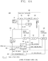
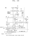
- FIGS. 6A and 6B are exemplary views illustrating a circuit configuration according to a detailed embodiment of the control device 400.
- FIG. 6A illustrates a power supply state when the laundry treating apparatus 1000 is turned off, namely, is in an OFF state
- FIG. 6B illustrates a power supply state when the laundry treating apparatus 1000 is in the standby state, namely, when the input unit 100 is waiting for receiving the signal.
- the second power supply portion 413 of the operation controller 410 may convert power received from the power supply source 10 into the second power when the laundry treating apparatus 1000 is turned off, and transfer the second power to the supply portion 431 of the driving controller 430.
- the supply portion 431 may convert the power transferred from the second power supply portion 413 into driving power of the driving performing portion 434, and transfer the converted driving power to the driving performing portion 434.
- the driving performing portion 434 may then operate by the driving power received from the supply portion 431. In this case, the driving performing portion 434 may be driven in a STOP mode that stops its operation according to the turn-off of the laundry treating apparatus 1000.
- standby power consumed by the laundry treating apparatus 1000 may be 0.5 W or less.
- the second power supply portion 413 of the operation controller 410 may convert power received from the power supply source 10 into the second power when the laundry treating apparatus 1000 is in the standby state, and transfer the second power to the supply portion 431 of the driving controller 430.
- the supply portion 431 may convert the power transferred from the second power supply portion 413 into driving power of the driving performing portion 434, and transfer the converted driving power to the driving performing portion 434.
- the driving performing portion 434 may then operate by the driving power received from the supply portion 431. In this case, the driving performing portion 434 may be driven in a standby mode in which it operates according to the standby state of the laundry treating apparatus 1000.
- the driving performing portion 434 may be driven by the driving power transferred from the supply portion 431, and control the third opening and closing portion 434 to connect the supply portion 431 to the input unit 100.
- the third opening and closing portion 434 may connect the supply portion 431 to the input unit 100 under the control of the driving performing portion 434, and the supply portion 431 may transfer the driving power to the input unit 100 through the third opening and closing portion 434.
- the input unit 100 may be driven by the driving power transferred from the supply portion 431 through the third opening and closing portion 434 to wait for the input of the signal.
- the laundry treating apparatus 1000 may include an input unit 100 to receive a signal for an operation command, an operation unit 200 to perform the operation, a display unit 300 to display information related to the operation, and a controller 400 to control the operation unit 200 and the display unit 300 so as to control the operation.
- controller 400 may be the control device 400 described above.
- the clothes processing apparatus 1000 may include the operation unit 200 to receive power for operating the laundry treating apparatus 1000 from the power supply source 10 and control the operation of the laundry treating apparatus 1000 by controlling the operation unit 200, the display controller 420 driven by power received from the operation controller 410 to control the display controller 300 to display information related to the laundry treating apparatus 1000, and the controller 400 having the driving controller 430 driven by power transferred from the display unit 420 and the operation controller 410 to control the power supply to each of the input unit 100, the operation controller 410, and the display controller 420 according to the driving state of the laundry treating apparatus 1000.
- the controller 400 can be driven according to the driving state of the laundry treating apparatus 1000.
- the operation controller 410 of the controller or control device 400 may receive power for driving the laundry treating apparatus 1000 from the power supply source 10, and control the operation unit 200 to control the operation of the laundry treating apparatus 1000. That is, the operation controller 410 may be a control module that controls the operation unit 200 to perform the operation of the laundry treating apparatus 1000.
- the operation controller 410 may be driven by power supplied from the power supply source 10. That is, the operation controller 410 may be driven based on the power supplied from the power supply source 10 to control the operation unit 200.
- the operation controller 410 may control the operation unit 200 according to the signal.
- the operation controller 410 may supply power to each of the operation unit 200 and the display unit 300 to drive each of the operation unit 200 and the display unit 300.
- the operation controller 410 may supply power to each of the operation unit 200 and the display unit 300 to drive the operation unit 200 and the display unit 300.
- the operation controller 410 may receive power from the power supply source 10 and supply the power to each of the operation unit 200 and the display unit 300.
- the operation controller 410 may also supply power to the driving controller 430 to drive the driving controller 430. That is, the operation controller 410 may supply power to the driving controller 430 to drive the driving controller 430.
- the operation controller 410 may communicate with the driving controller 430 to transmit and receive information on an operation state.
- the operation controller 410 may control the operation unit 200 according to a result of the communication with the driving controller 430.
- the operation controller 410 may receive the signal from the driving controller 430 and control the operation unit 200 according to the signal.
- the operation controller 410 may supply power to the driving controller 430, and thereafter the power supply may be controlled by the driving controller 430. That is, when the driving controller 430 is driven by power supplied from the operation controller 410, the power supply may be controlled by the driving controller 430.
- the display controller 420 of the controller 400 may be driven by the power transferred from the operation controller 410 so as to control the display unit 300 to display information related to the laundry treating apparatus 1000. That is, the display controller 420 may be a control module that controls the display unit 420 to display information related to the laundry treating apparatus 1000.
- the display controller 420 may be driven by power received from the driving controller 430. That is, the display controller 420 may be driven based on the power received from the driving controller 430 to control the display unit 300.
- the display controller 420 may communicate with the driving controller 430 to transmit and receive information on an operation state.
- the display controller 420 may control the display unit 300 according to a result of the communication with the driving controller 430.
- the display controller 420 may be driven by power received from the driving controller 430. That is, when the driving controller 430 is driven by receiving power from the operation controller 410, the display controller 420 may be driven by receiving power from the driving controller 430.
- the driving controller 430 may be driven by power received from the operation controller 410.
- the operation controller 430 may control the power supply to the input unit 100, the operation controller 410, and the display controller 420 according to an operating state of the laundry treating apparatus 1000, to control the input unit 100, the operation controller 410, and the display controller 420.
- the driving controller 430 may be a control module for controlling the power supply to each of the input unit 100, the operation controller 410, and the display controller 420 so as to drive each of the input unit 100, the operation controller 410, and the display controller 420.
- the driving controller 430 may be driven by power supplied from the operation controller 410 to control the power supply to each of the input unit 100, the operation controller 410, and the display controller 420.
- the driving of the controller 400 may be controlled.
- the driving controller 430 may communicate with the operation controller 410 and the display controller 420 to transmit and receive information related to an operation state.
- the driving controller 430 may control an operation of the controller 400 according to a result of the communication with the operation controller 410 and the display controller 420.
- the driving controller 430 may be driven by receiving power from the operation controller 410.
- the operation controller 430 may be driven by receiving power from the operation controller 410 so as to transfer power to the input unit 100 and the display controller 420. That is, the driving controller 430 may control operations of the input unit 100 and the display controller 420 by transferring power received from the operation controller 410 to the input unit 100 and the display controller 420, respectively.
- the driving controller 430 may also be driven by power received from the operation controller 410 so as to control the power supply to the operation controller 410. That is, when the driving controller 430 is driven by power supplied from the operation controller 410, the driving controller 430 may control the operation of the operation controller 410 by controlling the power supply to the operation controller 410.
- the driving controller 430 may also receive the signal from the input unit 100. When the input unit 100 receives a signal for an operation command, the driving controller 430 may receive the signal from the input unit 100 and transmit the signal to the operation controller 410.
- a detailed example of the laundry treating apparatus 1000 including the controller 400 may be as illustrated in FIG. 5 .
- the input unit 100 may receive a signal for an operation command from outside.
- the input unit 100 may include at least one of a communication portion 110 to communicate with a communication target device of the laundry treating apparatus 1000, so as to receive a control signal for an operation command from the communication target device, and a voice recognition portion 120 to recognize an operation command based on a voice signal input for the operation command. That is, the input unit 100 may include at least one of the communication portion 110 and the voice recognition portion 120 so as to receive the control signal through the communication portion 110 or the voice signal through the voice recognition portion 120.
- the communication portion 110 may receive the control signal through communication with the communication target device of the laundry treating apparatus 1000.
- the communication target device may be a device which remotely controls the laundry treating apparatus 1000.
- the communication portion 110 may transmit the control signal to the driving controller 430.
- the driving controller 430 may then transfer the control signal to the operation controller 410.
- the voice recognition portion 120 may recognize the operation command based on the voice signal input through the voice recognition mechanism provided in the laundry treating apparatus 1000. When the voice signal is received, the voice recognition portion 120 may recognize the operation command based on the voice signal and transmit the voice signal to the driving controller 430. The driving controller 430 may then transfer the voice signal to the operation controller 410.
- the input unit 100 which includes at least one of the communication portion 110 and the voice recognition portion 120 to receive the signal can be driven by receiving power from the driving controller 430. That is, when the driving controller 430 is driven by receiving power from the operation controller 410, the input unit 100 may be driven by receiving power from the driving controller 430.
- the input unit 100 may not be supplied with power while the laundry treating apparatus 1000 is turned off, while being driven by receiving power while the laundry treating apparatus 1000 is in the standby state. That is, the driving controller 430 may stop the power delivery to the input unit 100 while the laundry treating apparatus 1000 is turned off, and transfer power to the input unit 1000 while the laundry treating apparatus 1000 is in the standby state. Accordingly, the input unit 100 may be driven while the laundry treating apparatus 1000 is in the standby state, so as to receive the signal.
- the operation unit 200 may be a component for performing the operation of the laundry treating apparatus 1000.
- the operation unit 200 may include a plurality of components for performing the operation of the laundry treating apparatus 1000.
- the operation unit 200 may include at least one of a rotation portion such as a motor, a water supply portion, a drainage portion, and a heat supply portion.
- the operation unit 200 may operate by receiving power from the controller 400.
- the operation unit 200 may operate by receiving the first power from the first power supply portion 412 included in the controller 400.
- the operation unit 200 may be controlled by the controller 400.
- the operation unit 200 may be controlled by the operation controller 410 included in the controller 400.
- the operation unit 200 may be controlled by the operation performing portion 414 included in the operation controller 410.
- the operation unit 200 may be controlled by the controller 400 to perform the operation of the laundry treating apparatus 1000.
- the display unit 300 may be a component for displaying information related to the operation of the laundry treating apparatus 1000.
- the display unit 300 may include a plurality of components for displaying the information related to the operation of the laundry treating apparatus 1000.
- the display unit 300 may include at least one of a display, an input processor for processing information input through the display, and an output processor for processing information output through the display.
- the display unit 300 may operate by receiving power from the controller 400.
- the display unit 300 may operate by receiving the second power from the second power portion 413 included in the controller 400.
- the display unit 300 may be controlled by the controller 400.
- the display unit 300 may be controlled by the display controller 420 included in the controller 400.
- the display unit 300 may be controlled by the display performing portion 422 included in the display controller 420.
- the display unit 300 may be controlled by the controller 400 to display the information related to the operation of the laundry treating apparatus 1000.
- the controller 400 may be a component for controlling the operation of the laundry treating apparatus 1000.
- the controller 400 may include a plurality of components for controlling the operation of the laundry treating apparatus 1000.
- the controller 400 may include the operation controller 410, the display controller 420, and the driving controller 430.
- the controller 400 may be driven by power supplied from the power supply source 10.
- the operation controller 410 of the controller 400 may receive power supplied from the power supply source 10, and the driving controller 430 may operate by the power transferred from the operation controller 410 so as to control the power supply to the operation controller 410 and the display controller 420. That is, the driving controller 430 may control the power supply of the controller 400.
- the operation controller 410 may be driven by power supplied from the power supply source 10 to control the operation unit 200, thereby controlling the operation of the laundry treating apparatus 1000.
- the operation controller 410 may include a first opening and closing portion 411 for connecting or disconnecting the power supply source 10 and a first power supply portion 412, the power supply unit 412 for converting power supplied from the power supply source 10 into first power, a second power supply portion 413 for converting power supplied from the power supply source 10 into second power, and an operation performing portion 414 for controlling the operation controller 410 by receiving the first power from the first power supply portion 412.
- the first opening and closing portion 411 may be provided between the power supply source 10 and the first power supply portion 412, so as to connect or disconnect the power supply source 10 to or from the first power supply portion 412.
- the first opening and closing portion 411 can be controlled by the driving controller 430 to connect or disconnect the power supply source 10 to or from the first power supply portion 412.
- the first opening and closing portion 411 can disconnect the power supply source 10 from the first power supply portion 412 when the laundry treating apparatus 1000 is turned off and is in the standby state, while connecting the power supply source 10 to the first power supply portion 412 when the laundry treating apparatus 1000 is turned on.
- the first power supply portion 412 may be connected to the power supply source 10 through the first opening and closing portion 412, so as to receive power from the power supply source 10.
- the first power supply portion 412 may be a power converter for converting power supplied from the power supply source 10 to the first power.
- the first power supply portion 412 may receive power from the power supply source 10 and convert the received power into the first power when it is connected to the power supply source 10 by the first opening and closing portion 411, such that the first power can be supplied to the operation unit 20 and the operation performing portion 414.
- the second power supply portion 413 may be connected directly to the power supply source 10, so as to always receive power from the power supply source 10.
- the second power supply portion 412 may be a power converter for converting power supplied from the power supply source 10 to the second power.
- the second power supply portion 413 may convert power, which is supplied from the power supply source 10 at all times, into the second power, and transfer the second power to the display unit 300 and the driving controller 430.
- the operation performing portion 414 may operate by receiving the first power from the first power supply portion 412.
- the operation performing portion 414 may be a control part that controls the operation unit 200 by receiving the first power.
- the operation performing portion 414 may control the operations of the first opening and closing portion 411, the first power source portion 412, and the second power source portion 413 when it operates by receiving the first power.
- the operation performing portion 414 may communicate with the driving controller 430 to control the operation controller 410 according to a result of the communication.
- the operation performing portion 414 may receive the signal from the driving controller 430 and control the operation controller 410 according to the signal.
- the display controller 420 may be driven by power received from the operation controller 410 through the driving controller 420, to control the display unit 300 to display information related to the laundry treating apparatus 1000. That is, the driving controller 420 may transfer power received from the operation controller 410 to the display controller 420. The display controller 420 may operate by power received from the driving controller 420.
- the display controller 420 may include a conversion portion 421 to convert power received from the driving controller 430 into driving power of the display controller 420, and a display performing portion 422 to control the display controller 420 by receiving the driving power from the conversion portion 421.
- the conversion portion 421 may be a power converter that converts power received from the driving controller 430 into the driving power.
- the conversion portion 421 may convert a voltage of power received from the driving controller 430.
- the conversion portion 421 may convert power, which is received from the driving controller 430, into the driving power, when the laundry treating apparatus 1000 is turned on, and supply the converted driving power to the display performing portion 422.
- the display performing portion 422 may operate by receiving the driving power from the conversion portion 421.
- the display performing portion 422 may be a control part that operates by receiving the driving power so as to control the display unit 300.
- the display performing portion 422 may communicate with the input unit 100 and the driving controller 430 to control the display controller 420 according to a result of the communication.
- the driving controller 430 may be driven by power supplied from the operation controller 410 to control the operations of the operation controller 410 and the display controller 420, thereby controlling the operation of the control device 400. That is, the driving controller 430 may always receive power from the operation controller 410, and operate by the power received from the operation controller 410 at all times.
- the driving controller 430 may include a supply portion 431 to receive power from the operation controller 410 and convert the received power into driving power of the driving controller 430, a second opening and closing portion 432 to connect or disconnect the operation controller 410 and the display controller 420, a third opening and closing portion 433 to connect or disconnect the supply portion 431 and the input unit 100, and a driving performing portion 434 to operate by receiving driving power from the supply portion to perform the control of the driving controller 430.
- the supply portion 431 may be a power converter that converts power received from the driving controller 430 into driving power.
- the supply portion 431 may convert a voltage of power received from the driving controller 430.
- the supply portion 431 may convert power, which is received from the driving controller 430 at all times, into the driving power, and supply the converted driving power to the display performing portion 434.
- the supply portion 431 may also deliver power to each of the display controller 420 and the input unit 100 according to the operations of the second opening and closing portion 432 and the third opening and closing portion 433.
- the second opening and closing portion 432 may be an opening and closing mechanism which is disposed between the operation controller 410 and the display controller 420 to connect or disconnect the operation controller 410 to or from the display controller 420.
- the second opening and closing portion 432 may be controlled by the driving performing portion 434 to connect or disconnect the operation controller 410 to or from the display controller 420.
- the second opening and closing portion 432 may be controlled by the driving performing portion 434 according to the driving state of the laundry treating apparatus 1000.
- the second opening and closing portion 432 may disconnect the operation controller 410 from the display controller 420 when the laundry treating apparatus 1000 is turned off and is in the standby state, while connecting the operation controller 410 to the display controller 420 when the laundry treating apparatus 1000 is turned on.
- the third opening and closing portion 433 may be an opening and closing mechanism which is disposed between the supply portion 431 and the input unit 100 to connect or disconnect the supply portion 431 to or from the input unit 100.
- the third opening and closing portion 433 may be controlled by the driving performing portion 434 to connect or disconnect the supply portion 431 to or from the input unit 100.
- the third opening and closing portion 433 may be controlled by the driving performing portion 434 according to the driving state of the laundry treating apparatus 1000.
- the third opening and closing portion 433 may disconnect the supply portion 431 from the input unit 100 when the laundry treating apparatus 1000 is turned off and is in the standby state, while connecting the supply portion 431 to the input unit 100 when the laundry treating apparatus 1000 is turned on.
- the driving performing portion 434 may operate by receiving driving power from the supply portion 431.
- the driving performing portion 434 may be a control part that receives the driving power to control the operations of the first opening and closing portion 411, the second opening and closing portion 432, and the third opening and closing portion 433.
- the driving performing portion 434 may communicate with the input unit 100, the operation controller 410, and the display controller 420, to transmit a result of the communication to at least one of the input unit 100, the operation controller 410, and the display controller 420.
- the driving performing portion 434 may also receive a signal from the input unit 100.
- the driving performing portion 434 may receive the signal from the input unit 100 and transfer the signal to the operation controller 410.
- the driving performing portion 434 may change an operation mode according to the driving state of the laundry treating apparatus 1000.
- the driving performing portion 434 may control each of the second opening and closing portion 432 and the third opening and closing portion 433 according to the driving state of the laundry treating apparatus 1000.
- the driving performing portion 434 may control the second opening and closing unit 432 to be opened to disconnect the operation controller 410 from the display controller 420 when the laundry treating apparatus 1000 is turned off and is in the standby state, while controlling the second opening and closing portion 432 to be closed to connect the operation controller 410 to the display controller 420 when the laundry treating apparatus 1000 is turned on.
- the driving performing portion 434 may control the third opening and closing portion 433 to be opened to disconnect the supply portion 431 from the input unit 100 when the laundry treating apparatus 1000 is turned off and is in the standby state, while controlling the third opening and closing portion 433 to be closed to connect the supply portion 431 to the input unit 100 when the laundry treating apparatus 1000 is turned on.
- the embodiments of the device for controlling the laundry treating apparatus and the laundry treating apparatus having the same as described above may be carried out independently or in combination.
- the embodiments of the laundry treating apparatus and the control device thereof according to the present disclosure will be practiced by being applied to a control device, a control system, and a control method for every washing machine, a control device, a control system, and a control method of every drying machine, and the like, to which the technical features of this specification can be applied.
- the present disclosure may be usefully applied to a laundry treating apparatus employing Artificial Intelligence (AI), a control device and control system for the laundry treating apparatus employing the AI function, a control method of the laundry treating apparatus employing the AI function, and the like.
- AI Artificial Intelligence
- the technology described herein may not be limited to this, but may be embodied in a technical field of every laundry treating apparatus to which the technical scope of this specification can be applied.
Landscapes
- Engineering & Computer Science (AREA)
- Textile Engineering (AREA)
- General Engineering & Computer Science (AREA)
- Theoretical Computer Science (AREA)
- Physics & Mathematics (AREA)
- Computer Hardware Design (AREA)
- Computing Systems (AREA)
- General Physics & Mathematics (AREA)
- Computer Networks & Wireless Communication (AREA)
- Control Of Washing Machine And Dryer (AREA)
- Business, Economics & Management (AREA)
- Emergency Management (AREA)
- Power Engineering (AREA)
- Computational Linguistics (AREA)
- Health & Medical Sciences (AREA)
- Audiology, Speech & Language Pathology (AREA)
- Human Computer Interaction (AREA)
- Acoustics & Sound (AREA)
- Multimedia (AREA)
Abstract
Description
- The present disclosure relates to a device for controlling a laundry treating apparatus and a laundry treating apparatus having the same.
- The related art of the present disclosure relates to a power supply control of a laundry treating apparatus.
- A laundry treating apparatus refers to every apparatus which is configured to manage or treat clothes, such as washing, drying or removing wrinkles on garments, bedding, and the like, at home or at a place like a dry cleaner. Laundry treating apparatuses include a washing machine or washer, a dryer, a washer-dryer, and the like.
- A washing machine is a machine for washing clothes or bedding, and a dryer is a machine for drying clothes or bedding by removing moisture. A washer-dryer is a machine having both a washing function and a drying function.
- On the other hand, the dryer supplies hot air to an object to be treated, such as clothes or bedding put into a drum, to evaporate moisture contained in the object. Air which is discharged out of the drum after evaporating the moisture from the object contains such moisture so as to be in a hot and humid state.
- Such laundry treating apparatus may operate through a voice recognition system (or component) or a remote control system (or component). The laundry treating apparatus performs an operation according to an input command when a voice command is input through the voice recognition system or a control command is input through the remote control system. In order to perform the operation through the voice recognition system or the remote control system, a control part which controls an operation of the laundry treating apparatus should be in an idle (standby, waiting) state. In this instance, the control part controls a component, which performs the operation through the voice recognition system or remote control system to be in an idle state by supplying power to the component. Even while the component is in the idle state, the component consumes power, causing consumption of standby power. If the consumption of standby power is increased, power is consumed even while the laundry treating apparatus is not driven, thereby lowering energy efficiency. The unnecessary power consumption caused even while the operation through the voice recognition system or the remote control system is not carried out results in lowering effectiveness and efficiency of the laundry treating apparatus. In particular, in an environment requiring for standby power consumption of a predetermined level or lower, a problem may arise that the use of the laundry treating apparatus is limited.
- To solve such standby power problem, the related art, as illustrated in
FIG. 1A , has proposed a device for controlling a laundry treating apparatus, in which a display unit of the control device controls ON/OFF of both a main unit and the display unit itself through relays. The display turns off all of the relays when the laundry treating apparatus is off, while turning on its relay and turning off only the relay of the main unit in a standby state for a remote control, thereby waiting for the remote control. In the remote control standby state, the display unit receives a Wi-Fi signal so as to enable the remote control. - However, in the related art control device, the display unit controls power-on/off, and thereby there is a limit that a power supply of the control device circuit is controllable only by a power button when the control device is off. In addition, a MICOM of the display unit is ARM-based MICOM, which has a limit in reducing standby power merely by a saving mode. In addition, when an additional load, such as a communication module, a speaker or a microphone, which consumes power, is further provided in the voice recognition system, standby power is supplied even to the additional load in an idle state. As a result, standby power consumption is inconsistent or it is difficult to reduce the standby power down to a predetermined reference value.
- That is, in the related art, a technique for efficiently reducing the standby power of the laundry treating apparatus in a standby state for the voice recognition or the remote control has not been proposed, and the use/application of the laundry treating apparatus has been limited due to those problems.
- The present disclosure aims to improve or overcome the limitations of the related art.
- In particular, one aspect of the present disclosure is to provide a device for controlling a laundry treating apparatus, capable of reducing standby power consumed in a standby state for voice recognition or remote control, and a laundry treating apparatus having the same.
- Another aspect of the present disclosure is to provide a device for controlling a laundry treating apparatus, capable of smoothly performing an operation for waiting for voice recognition or remote control while reducing standby power consumption, and a laundry treating apparatus having the same.
- A device for controlling a laundry treating apparatus according to the present disclosure for solving those problems described above may control a power supply and an operation of the laundry treating apparatus according to a driving state of the laundry treating apparatus.
- Specifically, the control device may be provided with a driving controller for controlling a power supply of the laundry treating apparatus by utilizing/applying an Artificial Intelligence (AI) technology, so as to control the power supply according to a turn-off state, a standby state, and a turn-on state of the laundry treating apparatus.
- Also, the driving controller may receive a signal for a voice recognition control and a remote control with respect to the laundry treating apparatus and control the power supply based on the signal, in a standby state of the laundry treating apparatus.
- That is, in a device for controlling a laundry treating apparatus and a laundry treating apparatus having the same according to the present disclosure, a control part performing power supply and operation control for the laundry treating apparatus may be provided with a driving controller for controlling the power supply, such that the power supply can be controlled according to a driving state of the laundry treating apparatus.
- Technical features as described above can be embodied in a control device, a control system, a control method, or the like for a laundry treating apparatus, or a control device, a control system, a control method, or the like for an Artificial Intelligence (AI) laundry treating apparatus, and this specification provides a device for controlling a laundry treating apparatus and a laundry treating apparatus having the same, capable of solving those problems described above.
- A device for controlling a laundry treating apparatus according to the present disclosure having the technical features as described above may be configured to control a laundry treating apparatus, which may include an input unit configured to receive a signal input for an operation command, an operation unit configured to perform the operation according to the signal, and a display unit configured to display information related to the operation.
- The device may include an operation controller configured to receive power for driving the laundry treating apparatus from an external power supply source and control the operation unit to control the operation of the laundry treating apparatus, a display controller configured to be driven by power transferred from the operation controller and control the display unit to display the information related to the operation of the laundry treating apparatus, and a driving controller configured to be driven by power transferred from the operation controller and control a power supply to each of the input unit, the operation controller, and the display controller according to a driving state of the laundry treating apparatus, so as to control an operation of each of the input unit, the operation controller, and the display controller.
- In addition, a laundry treating apparatus according to the present disclosure having the technical features as described above may include at least one of an input unit configured to receive a signal input for an operation command, an operation unit configured to perform the operation according to the signal, a display unit configured to display information related to the operation, and a controller configured to control the operation unit and the display unit so as to control the operation.
- The controller may include an operation controller configured to receive power for driving the laundry treating apparatus from an external power supply source and control the operation unit to control the operation of the laundry treating apparatus, a display controller configured to be driven by power transferred from the operation controller and control the display unit to display information related to the laundry treating apparatus, and a driving controller configured to be driven by power transferred from the operation controller and control a power supply to each of the input unit, the operation controller, and the display controller according to a driving state of the laundry treating apparatus, so as to control an operation of each of the input unit, the operation controller, and the display controller.
- In a device for controlling a laundry treating apparatus and a laundry treating apparatus having the same according to the present invention, a control part which controls a power supply and an operation of the laundry treating apparatus may be provided with a driving controller for controlling the power supply thereof according to a driving state of the laundry treating apparatus, thereby reducing standby power consumed during a standby state of the laundry treating apparatus for a voice recognition control or a remote control.
- Preferably, the input unit comprises at least one of: a communication portion configured to communicate with a communication target device of the laundry treating apparatus to receive a control signal input for the operation command from the communication target device; and a voice recognition portion configured to recognize the operation command based on a voice signal when the voice signal is input for the operation command.
- Preferably, the input unit may stop a power transfer when the laundry treating apparatus is turned off.
- Preferably, the input unit may be driven by receiving power when the laundry treating apparatus is in a standby state.
- Preferably, the operation controller may comprise at least one of: a first opening and closing portion configured to connect or disconnect the power supply source to or from a first power supply portion; the first power supply portion configured to convert the power supplied from the power supply source into first power; a second power supply portion configured to convert the power supplied from the power supply source into second power; and an operation performing portion configured to be driven by receiving the first power from the first power supply portion so as to perform the control of the operation controller.
- Preferably, the first power supply portion may receive the power supplied from the power supply source when the power supply source is connected thereto by the first opening and closing portion, converts the received power into the first power.
- Preferably, the first power supply portion may supply the first power to the operation unit and the operation performing portion.
- Preferably, the second power supply portion may receive the power from the power supply source at all times, and/or may convert the received power into the second power, and/or may transfer the second power to the display unit and the driving controller.
- Preferably, the operation performing portion may communicate with the driving controller to perform the control of the operation controller according to a result of the communication.
- Preferably, the display controller may comprise a conversion portion configured to receive power from the driving controller and convert the power into driving power of the display controller; and/or a display performing portion configured to be driven by receiving the driving power from the conversion portion to perform the control of the display controller.
- Preferably, the conversion portion may receive the power from the driving controller when the laundry treating apparatus is turned on, and/or may convert the received power into the driving power, and/or may supply the driving power to the display performing portion.
- Preferably, the display performing portion may communicate with the input unit and the driving controller to perform the control of the operation controller according to a result of the communication.
- Preferably, the driving controller may comprises at least one of: a supply portion configured to receive power transferred from the operation controller and convert the received power into driving power of the driving controller; a second opening and closing portion configured to connect or disconnect the operation controller to or from the display controller; and a third opening and closing portion configured to connect or disconnect the supply portion to or from the input unit; and a display performing portion configured to be driven by receiving the driving power from the supply portion to perform the control of the driving controller.
- Preferably, the supply portion may receive power from the driving controller at all times, and/or may convert the received power into the driving power, and/or may supply the driving power to the driving performing portion.
- Preferably, the driving performing portion may control each of the second opening and closing portion and the third opening and closing portion according to a driving state of the laundry treating apparatus.
- Preferably, the second opening and closing portion may disconnect the operation controller from the display controller when the laundry treating apparatus is turned off and is in a standby state, and/or may connect the operation controller to the display controller when the laundry treating apparatus is turned on.
- Preferably, the third opening and closing portion may disconnect the supply portion from the input unit when the laundry treating apparatus is turned off and is in the standby state, and/or may connect the supply portion to the input unit when the laundry treating apparatus is turned on.
- In a further aspect a laundry treating apparatus, is provided comprising: an input unit configured to receive a signal input for an operation command; an operation unit configured to perform the operation according to the signal; a display unit configured to display information related to the operation; and a controller configured to control the operation unit and the display unit so as to control the operation.
- Preferably, the controller may be the device for controlling the laundry treating apparatus as described above.
- Accordingly, in the device for controlling the laundry treating apparatus and the laundry treating apparatus having the same, the standby power consumed during the standby state of the laundry treating apparatus for the voice recognition control or the remote control can be reduced and thus an increase in standby power can be secured for an additional load.
- In addition, in the device for controlling the laundry treating apparatus and the laundry treating apparatus having the same, the standby power can be reduced down to a predetermined reference level or lower, which may allow the laundry treating apparatus to be used under a specific environment requiring for standby power of the predetermined reference level or lower.
- In the device for controlling the laundry treating apparatus and the laundry treating apparatus having the same according to the present disclosure, as the control part which controls the power supply and the operation of the laundry treating apparatus may be provided with the driving controller for controlling the power supply thereof according to the driving state of the laundry treating apparatus, the standby power consumed can be reduced and also a waiting or standby operation for the voice recognition or remote control can be smoothly carried out.
- In the device for controlling the laundry treating apparatus and the laundry treating apparatus having the same according to the present disclosure, as the control part which controls the power supply and the operation of the laundry treating apparatus may be provided with the driving controller for controlling the power supply thereof according to the driving state of the laundry treating apparatus, unnecessary consumption of the standby power due to the standby operation for the voice recognition or remote control can be prevented.
- As a result, the device for controlling the laundry treating apparatus and the laundry treating apparatus having the same according to the present disclosure can secure improvement of limitations of the related art, and increase stability, reliability, applicability, efficiency, and effectiveness in a technical field of the laundry treating apparatus and laundry treating apparatuses employing Artificial Intelligence (AI).
-
-
FIG. 1 is an exemplary view illustrating a power-applied state during a standby state for a remote control of a laundry treating apparatus according to the related art. -
FIG. 2 is a block diagram illustrating a configuration of a laundry treating apparatus in accordance with one embodiment of the present disclosure. -
FIG. 3 is a block diagram illustrating a configuration of a device for controlling a laundry treating apparatus in accordance with one embodiment of the present disclosure. -
FIG. 4 is a block diagram illustrating functional relationship of components provided in a device for controlling a laundry treating apparatus according to the present disclosure. -
FIG. 5 is a block diagram illustrating a detailed configuration of a device for controlling a laundry treating apparatus and the laundry treating apparatus having the device in accordance with one embodiment of the present disclosure. -
FIG. 6A is an exemplary view illustrating a power-applied state when a laundry treating apparatus is turned off, in a device for controlling the laundry treating apparatus and the laundry treating apparatus having the device in accordance with one embodiment of the present disclosure. -
FIG. 6B is an exemplary view illustrating a power-applied state upon waiting for voice recognition and remote control in a device for controlling a laundry treating apparatus and a laundry treating apparatus having the same in accordance with one embodiment of the present disclosure. - Hereinafter, embodiments disclosed herein will be described in detail with reference to the accompanying drawings, and the same or similar components are denoted by the same reference numerals and redundant description thereof will be omitted. In describing the present invention, if a detailed explanation for a related known function or construction is considered to unnecessarily divert the gist of the present disclosure, such explanation has been omitted but would be understood by those skilled in the art.
- The accompanying drawings are used to help easily understand the technical idea of the present disclosure and it should be understood that the idea of the present disclosure is not limited by the accompanying drawings. The idea of the present disclosure should be construed to extend to any alterations, equivalents and substitutes besides the accompanying drawings.
- Hereafter, a device for controlling a laundry treating apparatus (hereinafter, referred to as a control device) according to the present disclosure will be described.
- As illustrated in
FIG. 2 , the control device refers to a device for controlling alaundry treating apparatus 1000. Thelaundry treating apparatus 1000 may include aninput unit 100 to receive a signal for an operation command, anoperation unit 200 to perform the operation according to the signal, and adisplay unit 300 to display information related to the operation. - The control device may be a
controller 400 included in thelaundry treating apparatus 1000. - Here, the
controller 400 is a control module which is included in thelaundry treating apparatus 1000 to control theoperation unit 200 and thedisplay unit 300 so as to control the operation of thelaundry treating apparatus 1000. - The
control device 400 may be made of at least one substrate. - The
control device 400 may include a plurality of circuit modules on the at least one substrate. - As illustrated in
FIG. 3 , thecontrol device 400 may include anoperation controller 410, adisplay controller 420, and a drivingcontroller 430. - Each of the
operation controller 410, thedisplay controller 420, and the drivingcontroller 430 included in thecontrol device 400 may be a circuit module including a plurality of circuit elements. - The
operation controller 410 may receive power for driving thelaundry treating apparatus 1000 from an externalpower supply source 10, and controls theoperation unit 200 to perform the operation of thelaundry treating apparatus 1000. That is, theoperation controller 410 may be a control module that controls theoperation unit 200 to perform the operation of thelaundry treating apparatus 1000. Theoperation controller 410 may be driven by the power supplied from thepower supply source 10. That is, theoperation controller 410 may be driven based on the power supplied from thepower supply source 10 to control theoperation unit 200. Theoperation controller 410 may control theoperation unit 200 according to the signal. Theoperation controller 410 may supply power to each of theoperation unit 200 and thedisplay unit 300 to drive each of theoperation unit 200 and thedisplay unit 300. In other words, theoperation controller 410 may supply power to each of theoperation unit 200 and thedisplay unit 300 to drive theoperation unit 200 and thedisplay unit 300. Theoperation controller 410 may receive power from thepower supply source 10 and transfer the power to each of theoperation unit 200 and thedisplay unit 300. Theoperation controller 410 may also transfer power to the drivingcontroller 430 to drive the drivingcontroller 430. That is, theoperation controller 410 may transfer power to the drivingcontroller 430 so that the drivingcontroller 430 can operate. - The
display controller 420 is driven by power received from theoperation controller 410 so as to control thedisplay unit 300 to display information related to thelaundry treating apparatus 1000. That is, thedisplay controller 420 may be a control module that controls thedisplay unit 420 to display information related to thelaundry treating apparatus 1000. Thedisplay controller 420 may be driven by power received from the drivingcontroller 430. That is, thedisplay controller 420 may be driven based on power received from the drivingcontroller 430 to control thedisplay unit 300. - The driving
controller 430 is driven by power received from theoperation controller 410. Theoperation controller 430 may control a power supply to theinput unit 100, theoperation controller 410, and thedisplay controller 420 according to a driving or operation state of thelaundry treating apparatus 1000, to control theinput unit 100, theoperation controller 410, and thedisplay controller 420. That is, the drivingcontroller 430 may be a control module for controlling a power supply to each of theinput unit 100, theoperation controller 410, and thedisplay controller 420 so as to drive each of theinput unit 100, theoperation controller 410, and thedisplay controller 420. Accordingly, the drivingcontroller 430 is driven by power supplied from theoperation controller 410 to control the power supply to theinput unit 100, theoperation controller 410, and thedisplay controller 420, so that thecontrol device 400 can operate. - Functions performed among the
operation controller 410, thedisplay controller 420, and the drivingcontroller 430 may have relationship as illustrated inFIG. 4 . - The
operation controller 410 may communicate with the drivingcontroller 430 to perform transmission and reception of information related to a driving or operation state with the drivingcontroller 430. Theoperation controller 410 may control theoperation unit 200 according to a result of the communication with the drivingcontroller 430. Theoperation controller 410 may receive the signal from the drivingcontroller 430 and control theoperation unit 200 according to the signal. Theoperation controller 410 may supply power to the drivingcontroller 430, and thereafter the power supply may be controlled by the drivingcontroller 430. That is, when the drivingcontroller 430 is driven by power supplied from theoperation controller 410, the power supply may be controlled by the drivingcontroller 430. - The
display controller 420 may communicate with the drivingcontroller 430 to perform transmission and reception of information related to a driving or operation state with the drivingcontroller 430. Thedisplay controller 420 may control thedisplay unit 300 according to a result of the communication with the drivingcontroller 430. Thedisplay controller 420 may be driven by power received from the drivingcontroller 430. That is, when the drivingcontroller 430 is driven by receiving power from theoperation controller 410, thedisplay controller 420 may be driven by receiving power from the drivingcontroller 430. - The driving
controller 430 may communicate with theoperation controller 410 and thedisplay controller 420 to transmit and receive information related to an operation state. The drivingcontroller 430 may control an operation of thecontrol device 400 according to a result of the communication with theoperation controller 410 and thedisplay controller 420. The drivingcontroller 430 may be driven by receiving power from theoperation controller 410. Theoperation controller 430 may be driven by receiving power from theoperation controller 410 so as to transfer power to theinput unit 100 and thedisplay controller 420. That is, the drivingcontroller 430 may control operations of theinput unit 100 and thedisplay controller 420 by transferring power received from theoperation controller 410 to theinput unit 100 and thedisplay controller 420, respectively. The drivingcontroller 430 may also be driven by power received from theoperation controller 410 so as to control a power supply to theoperation controller 410. That is, when the drivingcontroller 430 is driven by power supplied from theoperation controller 410, the drivingcontroller 430 may control the operation of theoperation controller 410 by controlling the power supply to theoperation controller 410. The drivingcontroller 430 may also receive a signal from theinput unit 100. When a signal of an operation command is input to theinput unit 100, the drivingcontroller 430 may receive the signal from theinput unit 100 and transmit the signal to theoperation controller 410. - In the
control device 400 including theoperation controller 410, thedisplay controller 420, and the drivingcontroller 430, the drivingcontroller 430 may control the power supply to each of theinput unit 100, theoperation controller 410, and thedisplay controller 420 according to the driving state of thelaundry treating apparatus 1000, thereby controlling the operation of thelaundry treating apparatus 1000. For example, the driving controller 4430 may control the power supply to each of theinput unit 100, theoperation controller 410, and thedisplay controller 420 according to a power-on/off (turn-on/off) mode, an idle or standby mode. For example, the drivingcontroller 430 may control the power supply to each of theinput unit 100, theoperation controller 410, and thedisplay controller 420, according to a state where thelaundry treating apparatus 1000 is stopped in operation, a state where thelaundry treating apparatus 1000 is in a standby state, or a state where thelaundry treating apparatus 1000 starts to operate. Here, the state where thelaundry treating apparatus 1000 is stopped in operation may be a power-off state of thelaundry treating apparatus 1000. The state where thelaundry treating apparatus 1000 is in the standby state may be a state where thelaundry treating apparatus 1000 is waiting for the input of the signal through theinput unit 100. Also, the state where thelaundry treating apparatus 1000 starts to operate may be a power-on state of thelaundry treating apparatus 1000 in response to the signal or a user's manipulation. Hereinafter, a detailed embodiment of thecontrol device 400 which controls the power supply to each of theinput unit 100, theoperation controller 410, and thedisplay controller 420 according to the driving state will be described with reference toFIG. 5 . - As illustrated in
FIG. 5 , thecontrol device 400 including theoperation controller 410, thedisplay controller 420, and the drivingcontroller 430 may be included in thelaundry treating apparatus 1000 to control thelaundry treating apparatus 1000. - The
input unit 100 may receive a signal for an operation command from outside. Theinput unit 100 may include at least one of acommunication portion 110 to communicate with a communication target device of thelaundry treating apparatus 1000, so as to receive a control signal for the operation command from the target device, and avoice recognition portion 120 to recognize an operation command based on a voice signal input for the operation command. That is, theinput unit 100 may include at least one of thecommunication portion 110 and thevoice recognition portion 120 so as to receive the control signal through thecommunication unit 110 or the voice signal through thevoice recognition unit 120. - The
communication portion 110 may receive the control signal through communication with the communication target device of thelaundry treating apparatus 1000. Here, the communication target device may be a device which remotely controls thelaundry treating apparatus 1000. For example, the target device may be a remote controller, a user terminal, or a voice recognition system cooperating with thelaundry treating apparatus 1000, all of which can remotely control thelaundry treating apparatus 1000. When thecommunication portion 110 receives the control signal, thecommunication portion 110 may transmit the control signal to the drivingcontroller 430. The drivingcontroller 430 may then transfer the control signal to theoperation controller 410. - The
voice recognition portion 120 may recognize the operation command based on the voice signal input through a voice recognition system provided in thelaundry treating apparatus 1000. Here, the voice recognition system may be a voice recognition module including a microphone for receiving a voice signal. When the voice signal is received, thevoice recognition portion 120 may recognize the operation command based on the voice signal and transmit the voice signal to the drivingcontroller 430. The drivingcontroller 430 may then transfer the voice signal to theoperation controller 410. - As such, the
input unit 100 which includes at least one of thecommunication portion 110 and thevoice recognition portion 120 to receive the signal can be driven by receiving power from the drivingcontroller 430. That is, when the drivingcontroller 430 is driven by receiving power from theoperation controller 410, theinput unit 100 may be driven by receiving power from the drivingcontroller 430. - The
input unit 100 may not be supplied with power when thelaundry treating apparatus 1000 is turned off, while being driven by receiving power during the standby state of thelaundry treating apparatus 1000. That is, the drivingcontroller 430 may stop the power transfer to theinput unit 100 while thelaundry treating apparatus 1000 is turned off, and transfer power to theinput unit 100 while thelaundry treating apparatus 1000 is in the standby state. Accordingly, theinput unit 100 may be driven while thelaundry treating apparatus 1000 is in the standby state, so as to receive the signal. - The
operation controller 410 may be driven by power supplied from thepower supply source 10 to control theoperation unit 200, thereby controlling the operation of thelaundry treating apparatus 1000. Theoperation controller 410 may include a first opening andclosing portion 411 for connecting or disconnecting thepower supply source 10 and a firstpower supply portion 412, thepower supply unit 412 for converting power supplied from thepower supply source 10 into first power, a secondpower supply portion 413 for converting power supplied from thepower supply source 10 into second power, and anoperation performing portion 414 for controlling theoperation controller 410 by receiving the first power from the firstpower supply portion 412. - The first opening and
closing portion 411 may be provided between thepower supply source 10 and the firstpower supply portion 412, so as to connect or disconnect thepower supply source 10 to or from the firstpower supply portion 412. For example, the first opening andclosing portion 411 may be a relay switch. The first opening andclosing portion 411 may be normally open while closed during operation. That is, the first opening andclosing portion 411 normally disconnects thepower supply source 10 from the firstpower supply portion 412, while connecting thepower supply source 10 to the firstpower supply portion 412 during operation. In this manner, the first opening andclosing portion 411 can interrupt power supplied from thepower supply source 10 to the firstpower supply portion 412. Accordingly, the power supply from thepower supply source 10 to the firstpower supply portion 412 can be stopped when thepower supply source 10 and the firstpower supply portion 412 are disconnected from each other, while power can be supplied from thepower supply source 10 to the firstpower supply portion 412 when thepower supply source 10 and the firstpower supply portion 412 are connected to each other. The first opening andclosing portion 411 can be controlled by the drivingcontroller 430 to connect or disconnect thepower supply source 10 to or from the firstpower supply portion 412. The first opening andclosing portion 411 may disconnect thepower supply source 10 from the firstpower supply portion 412 when thelaundry treating apparatus 1000 is turned off and is in the standby state, while connecting thepower supply source 10 to the firstpower supply portion 412 when thelaundry treating apparatus 1000 is turned on. That is, the drivingcontroller 430 may control the first opening andclosing portion 411 to be opened to disconnect thepower supply source 10 from the firstpower supply portion 412 when thelaundry treating apparatus 1000 is turned off or is in the standby state, while controlling the first opening andclosing portion 411 to be closed to connect thepower supply source 10 to the firstpower supply portion 412 when thelaundry treating apparatus 1000 is turned on. Accordingly, the drivingcontroller 430 may stop the power supply to the firstpower supply portion 412 when thelaundry treating apparatus 1000 is turned off and is in the standby state, while supplying power to the firstpower supply portion 412 when thelaundry treating apparatus 1000 is turned on. - The first
power supply portion 412 may be connected to thepower supply source 10 through the first opening andclosing portion 412, so as to receive power from thepower supply source 10. The firstpower supply portion 412 may be a power converter for converting power supplied from thepower supply source 10 to the first power. For example, the firstpower supply portion 412 may be a Switching Module Power Supply (SMPS). The first power may refer to power for operating theoperation unit 200. The first power may be DC power for operating theoperation unit 200. That is, the firstpower supply portion 412 may convert power supplied from thepower supply source 10 into the first power in the form of DC power. The firstpower supply portion 412 may receive power from thepower supply source 10 and convert the received power into the first power when it is connected to thepower supply source 10 by the first opening andclosing portion 411, such that the first power can be supplied to theoperation unit 200 and theoperation performing portion 414. That is, theoperation unit 200 and theoperation performing portion 414 may receive the first power when thepower supply source 10 and the firstpower supply portion 412 are connected to each other by the first opening andclosing portion 411. - The second
power supply portion 413 may be connected directly to thepower supply source 10, so as to always receive power from thepower supply source 10. The secondpower supply portion 412 may be a power converter for converting power supplied from thepower supply source 10 to the second power. For example, the secondpower supply portion 412 may be a Switching Module Power Supply (SMPS). The second power may refer to power for operating thedisplay unit 300. The second power may be DC power for operating thedisplay unit 300. That is, the secondpower supply portion 413 may convert power supplied from thepower supply source 10 into the second power in the form of DC power. The secondpower supply portion 413 may convert power, which is supplied from thepower supply source 10 at all times, into the second power, and transfer the second power to thedisplay unit 300 and the drivingcontroller 430. That is, thedisplay unit 300 and the drivingcontroller 430 may receive the second power at all times. - The
operation performing portion 414 may operate by receiving the first power from the firstpower supply portion 412. Theoperation performing portion 414 may be a control part that controls theoperation unit 200 by receiving the first power. For example, theoperation performing portion 414 may be a microcomputer (MICOM). That is, the first power may be power for operating the MICOM. Accordingly, theoperation performing portion 414 may operate when it receives the first power supplied from the firstpower supply portion 412, and may not operate when it does not receive the first power from the firstpower supply portion 412. Theoperation performing portion 414 may control the operations of the first opening andclosing portion 411, the firstpower source portion 412, and the secondpower source portion 413 when it operates by receiving the first power. That is, the first opening andclosing portion 411, the firstpower supply portion 412, and the secondpower supply portion 413 may be controlled by theoperation performing portion 414 when theoperation performing portion 414 operates by receiving the first power. Theoperation performing portion 414 may communicate with the drivingcontroller 430 to perform the control for theoperation controller 410 according to a result of the communication. Theoperation performing portion 414 may receive the signal from the drivingcontroller 430 and perform the control for theoperation controller 410 according to the signal. - The
display controller 420 may be driven by power received from theoperation controller 410 through the drivingcontroller 420, to control thedisplay unit 300 to display information related to thelaundry treating apparatus 1000. That is, thedisplay controller 420 may be driven by receiving power from the drivingcontroller 430 which has received the power from theoperation controller 410. Thedisplay controller 420 may operate by the power received from the drivingcontroller 420. Thedisplay controller 420 may include aconversion portion 421 to convert power received from the drivingcontroller 430 into driving power of thedisplay controller 420, and adisplay performing portion 422 to control thedisplay controller 420 by receiving the driving power from theconversion portion 421. - The
conversion portion 421 may be a power converter that converts power received from the drivingcontroller 430 into the driving power. For example, theconversion portion 421 may be a DC-DC converter. The driving power may be power for operating thedisplay performing portion 422. Theconversion portion 421 may convert a voltage of the power received from the drivingcontroller 430. For example, power of 12 V received from the drivingcontroller 430 may be converted into driving power of 5 V. Theconversion portion 421 may convert power, which is received from the drivingcontroller 430, into the driving power, and supply the converted driving power to thedisplay performing portion 422, when thelaundry treating apparatus 1000 is turned on. Accordingly, thedisplay performing portion 422 may operate by receiving the driving power when thelaundry treating apparatus 1000 is turned on. On the other hand, thedisplay performing portion 422 may not operate as it does not receive the driving power when thelaundry treating apparatus 1000 is turned off and is in the standby state. - The
display performing portion 422 may operate by receiving the driving power from theconversion portion 421. Thedisplay performing portion 422 may be a control part that operates by receiving the driving power so as to control thedisplay unit 300. For example, thedisplay performing portion 422 may be a microcomputer (MICOM). That is, the driving power may be power for operating the MICOM. Accordingly, thedisplay performing portion 422 may operate when the driving power is supplied from theconversion portion 421, and may not operate when the driving power is not supplied from theconversion portion 421. Thedisplay performing portion 422 may communicate with theinput unit 100 and the drivingcontroller 430 to control thedisplay controller 420 according to a result of the communication. - Accordingly, the driving
controller 430 may be driven by power received from theoperation controller 410 to control the operations of theoperation controller 410 and thedisplay controller 420, thereby controlling the operation of thecontrol device 400. That is, the drivingcontroller 430 may always receive power from theoperation controller 410, and operate by the power received from theoperation controller 410 at all times. The drivingcontroller 430 may include asupply portion 431 to receive power from theoperation controller 410 and convert the received power into driving power of the drivingcontroller 430, a second opening andclosing portion 432 to connect or disconnect theoperation controller 410 and thedisplay controller 420, a third opening andclosing portion 433 to connect or disconnect thesupply portion 431 and theinput unit 100, and adriving performing portion 434 to operate by receiving the driving power from thesupply portion 431 to control the drivingcontroller 430. - The
supply portion 431 may be a power converter that converts power received from the drivingcontroller 430 into the driving power. For example, thesupply portion 431 may be a DC-DC converter. The driving power may be power for operating thedriving performing portion 434. Thesupply portion 431 may convert a voltage of power received from the drivingcontroller 430. For example, power of 12 V received from the drivingcontroller 430 may be converted into driving power of 5 V. Thesupply portion 431 may convert power, which is received from the drivingcontroller 430 at all times, into the driving power, and supply the converted driving power to thedisplay performing portion 434. Accordingly, thedriving performing portion 434 may operate by receiving the driving power when thelaundry treating apparatus 1000 is turned on, is in the standby state, and is turned off. Thesupply portion 431 may also deliver power to each of thedisplay controller 420 and theinput unit 100 according to the operations of the second opening andclosing portion 432 and the third opening andclosing portion 433. - The second opening and
closing portion 432 may be an opening and closing mechanism which is disposed between theoperation controller 410 and thedisplay controller 420 to connect or disconnect theoperation controller 410 to and from thedisplay controller 420. For example, the second opening andclosing portion 432 may be a trigger switch. The second opening andclosing portion 432 may be normally open and closed during operation. That is, the second opening andclosing portion 432 may normally disconnect theoperation controller 410 from thedisplay controller 420, and connect theoperation controller 410 to thedisplay controller 420 during operation. In this manner, the second opening andclosing portion 432 can interrupt power supplied from theoperation controller 410 to thedisplay controller 420. Accordingly, power cannot be transferred from theoperation controller 410 to thedisplay controller 420 when theoperation controller 410 and thedisplay controller 420 are disconnected from each other, while power can be transferred from theoperation controller 410 to thedisplay controller 420 when theoperation controller 410 and thedisplay controller 420 are connected to each other. The second opening andclosing portion 432 may be controlled by thedriving performing portion 434 to connect or disconnect theoperation controller 410 to or from thedisplay controller 420. The second opening andclosing portion 432 may be controlled by thedriving performing portion 434 according to the driving state of thelaundry treating apparatus 1000. That is, thedriving performing portion 434 may control the second opening andclosing portion 432 according to the driving state. The second opening andclosing portion 432 may disconnect theoperation controller 410 from thedisplay controller 420 when thelaundry treating apparatus 1000 is turned off and is in the standby state, while connecting theoperation controller 410 to thedisplay controller 420 when thelaundry treating apparatus 1000 is turned on. That is, thedriving performing portion 434 may control the second opening andclosing unit 432 to be opened to disconnect theoperation controller 410 from thedisplay controller 420 when thelaundry treating apparatus 1000 is turned off and is in the standby state, while controlling the second opening andclosing portion 432 to be closed to connect theoperation controller 410 to thedisplay controller 420 when thelaundry treating apparatus 1000 is turned on. Accordingly, thedriving performing portion 434 may stop the power transfer to thedisplay controller 420 when thelaundry treating apparatus 1000 is turned off and is in the standby state, while transferring power to thedisplay controller 420 when thelaundry treating apparatus 1000 is turned on. - The third opening and
closing portion 433 may be an opening and closing mechanism which is disposed between thesupply portion 431 and theinput unit 100 to connect or disconnect thesupply portion 431 to or from theinput unit 100. For example, the third opening andclosing portion 433 may be a trigger switch. The third opening andclosing portion 433 may be normally open and closed during operation. That is, the third opening andclosing portion 433 may normally disconnect thesupply portion 431 from theinput unit 100, while connecting thesupply portion 431 to theinput unit 100 during operation. In this manner, the third opening andclosing portion 433 can interrupt power transferred from thesupply portion 431 to theinput unit 100. Accordingly, power cannot be transferred from thesupply portion 431 to theinput unit 100 when thesupply portion 431 and theinput unit 100 are disconnected from each other, while power can be transferred from thesupply portion 431 to theinput unit 100 when thesupply portion 431 and theinput unit 100 are connected to each other. The third opening andclosing portion 433 may be controlled by thedriving performing portion 434 to connect or disconnect thesupply portion 431 to or from theinput unit 100. The third opening andclosing portion 433 may be controlled by thedriving performing portion 434 according to the driving state of thelaundry treating apparatus 1000. That is, thedriving performing portion 434 may control the third opening andclosing portion 433 according to the driving state. The third opening andclosing portion 433 may disconnect thesupply portion 431 from theinput unit 100 when thelaundry treating apparatus 1000 is turned off and is in the standby state, while connecting thesupply portion 431 to theinput unit 100 when thelaundry treating apparatus 1000 is turned on. That is, thedriving performing portion 434 may control the third opening andclosing portion 433 to be opened to disconnect thesupply portion 431 from theinput unit 100 when thelaundry treating apparatus 1000 is turned off and is in the standby state, while controlling the third opening andclosing portion 433 to be closed to connect thesupply portion 431 to theinput unit 100 when thelaundry treating apparatus 1000 is turned on. Accordingly, thedriving performing portion 434 may stop the power transfer to theinput unit 100 when thelaundry treating apparatus 1000 is turned off and is in the standby state, while supplying power to theinput unit 100 when thelaundry treating apparatus 1000 is turned on. - The
driving performing portion 434 may operate by receiving the driving power from thesupply portion 431. Thedriving performing portion 434 may be a control part that receives the driving power to control the operations of the first opening andclosing portion 411, the second opening andclosing portion 432, and the third opening andclosing portion 433. For example, thedriving performing portion 434 may be a microcomputer (MICOM). That is, the driving power may be power for operating the MICOM. Accordingly, thedriving performing portion 434 can operate by receiving the driving power from thesupply portion 431. Thedriving performing portion 434 may communicate with theinput unit 100, theoperation controller 410, and thedisplay controller 420, to transmit a result of the communication to at least one of theinput unit 100, theoperation controller 410, and thedisplay controller 420. Thedriving performing portion 434 may also receive a signal from theinput unit 100. Thedriving performing portion 434 may receive the signal from theinput unit 100 and transfer the signal to theoperation controller 410. Thedriving performing portion 434 may change an operation mode according to the driving state of thelaundry treating apparatus 1000. For example, thedriving performing portion 434 may be set to a mode of stopping the operation of thelaundry treating apparatus 1000 when thelaundry treating apparatus 1000 is turned off, and set to a mode of maintaining the operation when thelaundry treating apparatus 1000 is in the standby state, thereby controlling power consumption according to the driving state of thelaundry treating apparatus 1000. Thedriving performing portion 434 may control each of the second opening andclosing portion 432 and the third opening andclosing portion 433 according to the driving state of thelaundry treating apparatus 1000. Thedriving performing portion 434 may control the second opening andclosing unit 432 to be opened to disconnect theoperation controller 410 from thedisplay controller 420 when thelaundry treating apparatus 1000 is turned off and is in the standby state, while controlling the second opening andclosing portion 432 to be closed to connect theoperation controller 410 to thedisplay controller 420 when thelaundry treating apparatus 1000 is turned on. That is, thedriving performing portion 434 may stop the power transfer to thedisplay controller 420 when thelaundry treating apparatus 1000 is turned off and is in the standby state, while transferring power to thedisplay controller 420 when thelaundry treating apparatus 1000 is turned on. Thedriving performing portion 434 may control the third opening andclosing portion 433 to be opened to disconnect thesupply portion 431 from theinput unit 100 when thelaundry treating apparatus 1000 is turned off and is in the standby state, while controlling the third opening andclosing portion 433 to be closed to connect thesupply portion 431 to theinput unit 100 when thelaundry treating apparatus 1000 is turned on. That is, thedriving performing portion 434 may stop the power supply to theinput unit 100 when thelaundry treating apparatus 1000 is turned off and is in the standby state, while supplying power to theinput unit 100 when thelaundry treating apparatus 1000 is turned on. - Hereinafter, a detailed embodiment of the
control device 400 that controls the power supply according to the driving state of thelaundry treating apparatus 1000 will be described with reference toFIGS. 6A and6B .FIGS. 6A and6B are exemplary views illustrating a circuit configuration according to a detailed embodiment of thecontrol device 400.FIG. 6A illustrates a power supply state when thelaundry treating apparatus 1000 is turned off, namely, is in an OFF state, andFIG. 6B illustrates a power supply state when thelaundry treating apparatus 1000 is in the standby state, namely, when theinput unit 100 is waiting for receiving the signal. - As illustrated in
FIG. 6A , in thecontrol device 400, the secondpower supply portion 413 of theoperation controller 410 may convert power received from thepower supply source 10 into the second power when thelaundry treating apparatus 1000 is turned off, and transfer the second power to thesupply portion 431 of the drivingcontroller 430. Thesupply portion 431 may convert the power transferred from the secondpower supply portion 413 into driving power of thedriving performing portion 434, and transfer the converted driving power to thedriving performing portion 434. Thedriving performing portion 434 may then operate by the driving power received from thesupply portion 431. In this case, thedriving performing portion 434 may be driven in a STOP mode that stops its operation according to the turn-off of thelaundry treating apparatus 1000. That is, when thelaundry treating apparatus 1000 is turned off, power may be applied only to the secondpower supply portion 413, thesupply portion 431, and thedriving performing portion 434, so that standby power can be consumed only by the secondpower supply portion 413, thesupply portion 431, and thedriving performing portion 434. When the power supply is carried out in this manner, standby power consumed by thelaundry treating apparatus 1000 may be 0.5 W or less. - As illustrated in
FIG. 6A , in thecontrol device 400, the secondpower supply portion 413 of theoperation controller 410 may convert power received from thepower supply source 10 into the second power when thelaundry treating apparatus 1000 is in the standby state, and transfer the second power to thesupply portion 431 of the drivingcontroller 430. Thesupply portion 431 may convert the power transferred from the secondpower supply portion 413 into driving power of thedriving performing portion 434, and transfer the converted driving power to thedriving performing portion 434. Thedriving performing portion 434 may then operate by the driving power received from thesupply portion 431. In this case, thedriving performing portion 434 may be driven in a standby mode in which it operates according to the standby state of thelaundry treating apparatus 1000. Thedriving performing portion 434 may be driven by the driving power transferred from thesupply portion 431, and control the third opening andclosing portion 434 to connect thesupply portion 431 to theinput unit 100. The third opening andclosing portion 434 may connect thesupply portion 431 to theinput unit 100 under the control of thedriving performing portion 434, and thesupply portion 431 may transfer the driving power to theinput unit 100 through the third opening andclosing portion 434. Theinput unit 100 may be driven by the driving power transferred from thesupply portion 431 through the third opening andclosing portion 434 to wait for the input of the signal. That is, when thelaundry treating apparatus 1000 is in the standby state, power may be applied only to the secondpower supply portion 413, thesupply portion 431, the third opening andclosing portion 433, thedriving performing portion 434, and theinput unit 100, so that standby power can be consumed only by the secondpower supply portion 413, thesupply portion 431, the third opening andclosing portion 433, thedriving performing portion 434, and theinput unit 100. When the power supply is carried out in this manner, standby power consumed by thelaundry treating apparatus 1000 may be 2 W or less. - Hereinafter, a laundry treating apparatus according to the present disclosure will be described.
- As illustrated in
FIG. 2 , thelaundry treating apparatus 1000 may include aninput unit 100 to receive a signal for an operation command, anoperation unit 200 to perform the operation, adisplay unit 300 to display information related to the operation, and acontroller 400 to control theoperation unit 200 and thedisplay unit 300 so as to control the operation. - Here, the
controller 400 may be thecontrol device 400 described above. - That is, as illustrated in
FIG. 3 , theclothes processing apparatus 1000 may include theoperation unit 200 to receive power for operating thelaundry treating apparatus 1000 from thepower supply source 10 and control the operation of thelaundry treating apparatus 1000 by controlling theoperation unit 200, thedisplay controller 420 driven by power received from theoperation controller 410 to control thedisplay controller 300 to display information related to thelaundry treating apparatus 1000, and thecontroller 400 having the drivingcontroller 430 driven by power transferred from thedisplay unit 420 and theoperation controller 410 to control the power supply to each of theinput unit 100, theoperation controller 410, and thedisplay controller 420 according to the driving state of thelaundry treating apparatus 1000. With the configuration, thecontroller 400 can be driven according to the driving state of thelaundry treating apparatus 1000. - The
operation controller 410 of the controller orcontrol device 400 may receive power for driving thelaundry treating apparatus 1000 from thepower supply source 10, and control theoperation unit 200 to control the operation of thelaundry treating apparatus 1000. That is, theoperation controller 410 may be a control module that controls theoperation unit 200 to perform the operation of thelaundry treating apparatus 1000. Theoperation controller 410 may be driven by power supplied from thepower supply source 10. That is, theoperation controller 410 may be driven based on the power supplied from thepower supply source 10 to control theoperation unit 200. Theoperation controller 410 may control theoperation unit 200 according to the signal. Theoperation controller 410 may supply power to each of theoperation unit 200 and thedisplay unit 300 to drive each of theoperation unit 200 and thedisplay unit 300. That is, theoperation controller 410 may supply power to each of theoperation unit 200 and thedisplay unit 300 to drive theoperation unit 200 and thedisplay unit 300. Theoperation controller 410 may receive power from thepower supply source 10 and supply the power to each of theoperation unit 200 and thedisplay unit 300. Theoperation controller 410 may also supply power to the drivingcontroller 430 to drive the drivingcontroller 430. That is, theoperation controller 410 may supply power to the drivingcontroller 430 to drive the drivingcontroller 430. - As illustrated in
FIG. 4 , theoperation controller 410 may communicate with the drivingcontroller 430 to transmit and receive information on an operation state. Theoperation controller 410 may control theoperation unit 200 according to a result of the communication with the drivingcontroller 430. Theoperation controller 410 may receive the signal from the drivingcontroller 430 and control theoperation unit 200 according to the signal. Theoperation controller 410 may supply power to the drivingcontroller 430, and thereafter the power supply may be controlled by the drivingcontroller 430. That is, when the drivingcontroller 430 is driven by power supplied from theoperation controller 410, the power supply may be controlled by the drivingcontroller 430. - The
display controller 420 of thecontroller 400 may be driven by the power transferred from theoperation controller 410 so as to control thedisplay unit 300 to display information related to thelaundry treating apparatus 1000. That is, thedisplay controller 420 may be a control module that controls thedisplay unit 420 to display information related to thelaundry treating apparatus 1000. Thedisplay controller 420 may be driven by power received from the drivingcontroller 430. That is, thedisplay controller 420 may be driven based on the power received from the drivingcontroller 430 to control thedisplay unit 300. - As illustrated in
FIG. 4 , thedisplay controller 420 may communicate with the drivingcontroller 430 to transmit and receive information on an operation state. Thedisplay controller 420 may control thedisplay unit 300 according to a result of the communication with the drivingcontroller 430. Thedisplay controller 420 may be driven by power received from the drivingcontroller 430. That is, when the drivingcontroller 430 is driven by receiving power from theoperation controller 410, thedisplay controller 420 may be driven by receiving power from the drivingcontroller 430. - In the
controller 400, the drivingcontroller 430 may be driven by power received from theoperation controller 410. Theoperation controller 430 may control the power supply to theinput unit 100, theoperation controller 410, and thedisplay controller 420 according to an operating state of thelaundry treating apparatus 1000, to control theinput unit 100, theoperation controller 410, and thedisplay controller 420. That is, the drivingcontroller 430 may be a control module for controlling the power supply to each of theinput unit 100, theoperation controller 410, and thedisplay controller 420 so as to drive each of theinput unit 100, theoperation controller 410, and thedisplay controller 420. Accordingly, the drivingcontroller 430 may be driven by power supplied from theoperation controller 410 to control the power supply to each of theinput unit 100, theoperation controller 410, and thedisplay controller 420. As a result, the driving of thecontroller 400 may be controlled. - The driving
controller 430, as illustrated inFIG. 4 , may communicate with theoperation controller 410 and thedisplay controller 420 to transmit and receive information related to an operation state. The drivingcontroller 430 may control an operation of thecontroller 400 according to a result of the communication with theoperation controller 410 and thedisplay controller 420. The drivingcontroller 430 may be driven by receiving power from theoperation controller 410. Theoperation controller 430 may be driven by receiving power from theoperation controller 410 so as to transfer power to theinput unit 100 and thedisplay controller 420. That is, the drivingcontroller 430 may control operations of theinput unit 100 and thedisplay controller 420 by transferring power received from theoperation controller 410 to theinput unit 100 and thedisplay controller 420, respectively. The drivingcontroller 430 may also be driven by power received from theoperation controller 410 so as to control the power supply to theoperation controller 410. That is, when the drivingcontroller 430 is driven by power supplied from theoperation controller 410, the drivingcontroller 430 may control the operation of theoperation controller 410 by controlling the power supply to theoperation controller 410. The drivingcontroller 430 may also receive the signal from theinput unit 100. When theinput unit 100 receives a signal for an operation command, the drivingcontroller 430 may receive the signal from theinput unit 100 and transmit the signal to theoperation controller 410. - A detailed example of the
laundry treating apparatus 1000 including thecontroller 400 may be as illustrated inFIG. 5 . - In the
laundry treating apparatus 1000, theinput unit 100 may receive a signal for an operation command from outside. Theinput unit 100 may include at least one of acommunication portion 110 to communicate with a communication target device of thelaundry treating apparatus 1000, so as to receive a control signal for an operation command from the communication target device, and avoice recognition portion 120 to recognize an operation command based on a voice signal input for the operation command. That is, theinput unit 100 may include at least one of thecommunication portion 110 and thevoice recognition portion 120 so as to receive the control signal through thecommunication portion 110 or the voice signal through thevoice recognition portion 120. - The
communication portion 110 may receive the control signal through communication with the communication target device of thelaundry treating apparatus 1000. Here, the communication target device may be a device which remotely controls thelaundry treating apparatus 1000. When thecommunication portion 110 receives the control signal, thecommunication portion 110 may transmit the control signal to the drivingcontroller 430. The drivingcontroller 430 may then transfer the control signal to theoperation controller 410. - The
voice recognition portion 120 may recognize the operation command based on the voice signal input through the voice recognition mechanism provided in thelaundry treating apparatus 1000. When the voice signal is received, thevoice recognition portion 120 may recognize the operation command based on the voice signal and transmit the voice signal to the drivingcontroller 430. The drivingcontroller 430 may then transfer the voice signal to theoperation controller 410. - As such, the
input unit 100 which includes at least one of thecommunication portion 110 and thevoice recognition portion 120 to receive the signal can be driven by receiving power from the drivingcontroller 430. That is, when the drivingcontroller 430 is driven by receiving power from theoperation controller 410, theinput unit 100 may be driven by receiving power from the drivingcontroller 430. - The
input unit 100 may not be supplied with power while thelaundry treating apparatus 1000 is turned off, while being driven by receiving power while thelaundry treating apparatus 1000 is in the standby state. That is, the drivingcontroller 430 may stop the power delivery to theinput unit 100 while thelaundry treating apparatus 1000 is turned off, and transfer power to theinput unit 1000 while thelaundry treating apparatus 1000 is in the standby state. Accordingly, theinput unit 100 may be driven while thelaundry treating apparatus 1000 is in the standby state, so as to receive the signal. - In the
laundry treating apparatus 1000, theoperation unit 200 may be a component for performing the operation of thelaundry treating apparatus 1000. Theoperation unit 200 may include a plurality of components for performing the operation of thelaundry treating apparatus 1000. For example, theoperation unit 200 may include at least one of a rotation portion such as a motor, a water supply portion, a drainage portion, and a heat supply portion. Theoperation unit 200 may operate by receiving power from thecontroller 400. Theoperation unit 200 may operate by receiving the first power from the firstpower supply portion 412 included in thecontroller 400. Theoperation unit 200 may be controlled by thecontroller 400. Theoperation unit 200 may be controlled by theoperation controller 410 included in thecontroller 400. For example, theoperation unit 200 may be controlled by theoperation performing portion 414 included in theoperation controller 410. Theoperation unit 200 may be controlled by thecontroller 400 to perform the operation of thelaundry treating apparatus 1000. - In the
laundry treating apparatus 1000, thedisplay unit 300 may be a component for displaying information related to the operation of thelaundry treating apparatus 1000. Thedisplay unit 300 may include a plurality of components for displaying the information related to the operation of thelaundry treating apparatus 1000. For example, thedisplay unit 300 may include at least one of a display, an input processor for processing information input through the display, and an output processor for processing information output through the display. Thedisplay unit 300 may operate by receiving power from thecontroller 400. Thedisplay unit 300 may operate by receiving the second power from thesecond power portion 413 included in thecontroller 400. Thedisplay unit 300 may be controlled by thecontroller 400. Thedisplay unit 300 may be controlled by thedisplay controller 420 included in thecontroller 400. For example, thedisplay unit 300 may be controlled by thedisplay performing portion 422 included in thedisplay controller 420. Thedisplay unit 300 may be controlled by thecontroller 400 to display the information related to the operation of thelaundry treating apparatus 1000. - In the
clothing processing apparatus 1000, thecontroller 400 may be a component for controlling the operation of thelaundry treating apparatus 1000. Thecontroller 400 may include a plurality of components for controlling the operation of thelaundry treating apparatus 1000. For example, thecontroller 400 may include theoperation controller 410, thedisplay controller 420, and the drivingcontroller 430. Thecontroller 400 may be driven by power supplied from thepower supply source 10. Theoperation controller 410 of thecontroller 400 may receive power supplied from thepower supply source 10, and the drivingcontroller 430 may operate by the power transferred from theoperation controller 410 so as to control the power supply to theoperation controller 410 and thedisplay controller 420. That is, the drivingcontroller 430 may control the power supply of thecontroller 400. - In the
controller 400, theoperation controller 410 may be driven by power supplied from thepower supply source 10 to control theoperation unit 200, thereby controlling the operation of thelaundry treating apparatus 1000. Theoperation controller 410 may include a first opening andclosing portion 411 for connecting or disconnecting thepower supply source 10 and a firstpower supply portion 412, thepower supply unit 412 for converting power supplied from thepower supply source 10 into first power, a secondpower supply portion 413 for converting power supplied from thepower supply source 10 into second power, and anoperation performing portion 414 for controlling theoperation controller 410 by receiving the first power from the firstpower supply portion 412. - The first opening and
closing portion 411 may be provided between thepower supply source 10 and the firstpower supply portion 412, so as to connect or disconnect thepower supply source 10 to or from the firstpower supply portion 412. The first opening andclosing portion 411 can be controlled by the drivingcontroller 430 to connect or disconnect thepower supply source 10 to or from the firstpower supply portion 412. The first opening andclosing portion 411 can disconnect thepower supply source 10 from the firstpower supply portion 412 when thelaundry treating apparatus 1000 is turned off and is in the standby state, while connecting thepower supply source 10 to the firstpower supply portion 412 when thelaundry treating apparatus 1000 is turned on. - The first
power supply portion 412 may be connected to thepower supply source 10 through the first opening andclosing portion 412, so as to receive power from thepower supply source 10. The firstpower supply portion 412 may be a power converter for converting power supplied from thepower supply source 10 to the first power. When the firstpower supply portion 412 may receive power from thepower supply source 10 and convert the received power into the first power when it is connected to thepower supply source 10 by the first opening andclosing portion 411, such that the first power can be supplied to the operation unit 20 and theoperation performing portion 414. - The second
power supply portion 413 may be connected directly to thepower supply source 10, so as to always receive power from thepower supply source 10. The secondpower supply portion 412 may be a power converter for converting power supplied from thepower supply source 10 to the second power. The secondpower supply portion 413 may convert power, which is supplied from thepower supply source 10 at all times, into the second power, and transfer the second power to thedisplay unit 300 and the drivingcontroller 430. - The
operation performing portion 414 may operate by receiving the first power from the firstpower supply portion 412. Theoperation performing portion 414 may be a control part that controls theoperation unit 200 by receiving the first power. Theoperation performing portion 414 may control the operations of the first opening andclosing portion 411, the firstpower source portion 412, and the secondpower source portion 413 when it operates by receiving the first power. Theoperation performing portion 414 may communicate with the drivingcontroller 430 to control theoperation controller 410 according to a result of the communication. Theoperation performing portion 414 may receive the signal from the drivingcontroller 430 and control theoperation controller 410 according to the signal. - In the
controller 400, thedisplay controller 420 may be driven by power received from theoperation controller 410 through the drivingcontroller 420, to control thedisplay unit 300 to display information related to thelaundry treating apparatus 1000. That is, the drivingcontroller 420 may transfer power received from theoperation controller 410 to thedisplay controller 420. Thedisplay controller 420 may operate by power received from the drivingcontroller 420. Thedisplay controller 420 may include aconversion portion 421 to convert power received from the drivingcontroller 430 into driving power of thedisplay controller 420, and adisplay performing portion 422 to control thedisplay controller 420 by receiving the driving power from theconversion portion 421. - The
conversion portion 421 may be a power converter that converts power received from the drivingcontroller 430 into the driving power. Theconversion portion 421 may convert a voltage of power received from the drivingcontroller 430. Theconversion portion 421 may convert power, which is received from the drivingcontroller 430, into the driving power, when thelaundry treating apparatus 1000 is turned on, and supply the converted driving power to thedisplay performing portion 422. - The
display performing portion 422 may operate by receiving the driving power from theconversion portion 421. Thedisplay performing portion 422 may be a control part that operates by receiving the driving power so as to control thedisplay unit 300. Thedisplay performing portion 422 may communicate with theinput unit 100 and the drivingcontroller 430 to control thedisplay controller 420 according to a result of the communication. - In the
controller 400, the drivingcontroller 430 may be driven by power supplied from theoperation controller 410 to control the operations of theoperation controller 410 and thedisplay controller 420, thereby controlling the operation of thecontrol device 400. That is, the drivingcontroller 430 may always receive power from theoperation controller 410, and operate by the power received from theoperation controller 410 at all times. The drivingcontroller 430 may include asupply portion 431 to receive power from theoperation controller 410 and convert the received power into driving power of the drivingcontroller 430, a second opening andclosing portion 432 to connect or disconnect theoperation controller 410 and thedisplay controller 420, a third opening andclosing portion 433 to connect or disconnect thesupply portion 431 and theinput unit 100, and adriving performing portion 434 to operate by receiving driving power from the supply portion to perform the control of the drivingcontroller 430. - The
supply portion 431 may be a power converter that converts power received from the drivingcontroller 430 into driving power. Thesupply portion 431 may convert a voltage of power received from the drivingcontroller 430. Thesupply portion 431 may convert power, which is received from the drivingcontroller 430 at all times, into the driving power, and supply the converted driving power to thedisplay performing portion 434. Thesupply portion 431 may also deliver power to each of thedisplay controller 420 and theinput unit 100 according to the operations of the second opening andclosing portion 432 and the third opening andclosing portion 433. - The second opening and
closing portion 432 may be an opening and closing mechanism which is disposed between theoperation controller 410 and thedisplay controller 420 to connect or disconnect theoperation controller 410 to or from thedisplay controller 420. The second opening andclosing portion 432 may be controlled by thedriving performing portion 434 to connect or disconnect theoperation controller 410 to or from thedisplay controller 420. The second opening andclosing portion 432 may be controlled by thedriving performing portion 434 according to the driving state of thelaundry treating apparatus 1000. The second opening andclosing portion 432 may disconnect theoperation controller 410 from thedisplay controller 420 when thelaundry treating apparatus 1000 is turned off and is in the standby state, while connecting theoperation controller 410 to thedisplay controller 420 when thelaundry treating apparatus 1000 is turned on. - The third opening and
closing portion 433 may be an opening and closing mechanism which is disposed between thesupply portion 431 and theinput unit 100 to connect or disconnect thesupply portion 431 to or from theinput unit 100. The third opening andclosing portion 433 may be controlled by thedriving performing portion 434 to connect or disconnect thesupply portion 431 to or from theinput unit 100. The third opening andclosing portion 433 may be controlled by thedriving performing portion 434 according to the driving state of thelaundry treating apparatus 1000. The third opening andclosing portion 433 may disconnect thesupply portion 431 from theinput unit 100 when thelaundry treating apparatus 1000 is turned off and is in the standby state, while connecting thesupply portion 431 to theinput unit 100 when thelaundry treating apparatus 1000 is turned on. - The
driving performing portion 434 may operate by receiving driving power from thesupply portion 431. Thedriving performing portion 434 may be a control part that receives the driving power to control the operations of the first opening andclosing portion 411, the second opening andclosing portion 432, and the third opening andclosing portion 433. Thedriving performing portion 434 may communicate with theinput unit 100, theoperation controller 410, and thedisplay controller 420, to transmit a result of the communication to at least one of theinput unit 100, theoperation controller 410, and thedisplay controller 420. Thedriving performing portion 434 may also receive a signal from theinput unit 100. Thedriving performing portion 434 may receive the signal from theinput unit 100 and transfer the signal to theoperation controller 410. Thedriving performing portion 434 may change an operation mode according to the driving state of thelaundry treating apparatus 1000. Thedriving performing portion 434 may control each of the second opening andclosing portion 432 and the third opening andclosing portion 433 according to the driving state of thelaundry treating apparatus 1000. Thedriving performing portion 434 may control the second opening andclosing unit 432 to be opened to disconnect theoperation controller 410 from thedisplay controller 420 when thelaundry treating apparatus 1000 is turned off and is in the standby state, while controlling the second opening andclosing portion 432 to be closed to connect theoperation controller 410 to thedisplay controller 420 when thelaundry treating apparatus 1000 is turned on. Thedriving performing portion 434 may control the third opening andclosing portion 433 to be opened to disconnect thesupply portion 431 from theinput unit 100 when thelaundry treating apparatus 1000 is turned off and is in the standby state, while controlling the third opening andclosing portion 433 to be closed to connect thesupply portion 431 to theinput unit 100 when thelaundry treating apparatus 1000 is turned on. - The embodiments of the device for controlling the laundry treating apparatus and the laundry treating apparatus having the same as described above may be carried out independently or in combination. In addition, the embodiments of the laundry treating apparatus and the control device thereof according to the present disclosure will be practiced by being applied to a control device, a control system, and a control method for every washing machine, a control device, a control system, and a control method of every drying machine, and the like, to which the technical features of this specification can be applied. In particular, the present disclosure may be usefully applied to a laundry treating apparatus employing Artificial Intelligence (AI), a control device and control system for the laundry treating apparatus employing the AI function, a control method of the laundry treating apparatus employing the AI function, and the like. However, the technology described herein may not be limited to this, but may be embodied in a technical field of every laundry treating apparatus to which the technical scope of this specification can be applied.
- Although specific embodiments of the present disclosure have been described so far, various modifications are possible without departing from the scope of the present disclosure. Therefore, the scope of the present disclosure should not be limited to the described embodiments, but should be determined not only by the claims below, but also by the equivalents of the claims.
- As described above, although the present disclosure has been described by way of limited embodiments and drawings, it should be understood that the present disclosure is not limited to the above-described embodiments and various modifications and changes are made by those skilled in the art to which the present disclosure pertains. Accordingly, the scope of the present disclosure should be understood only by the claims set forth below, and all equivalent or equivalent modifications thereof will belong to the scope of the present disclosure.
Claims (15)
- A device for controlling a laundry treating apparatus, comprising an input unit (100) configured to receive a signal for an operation command, an operation unit (200) configured to perform the operation according to the signal, and a display unit (300) configured to display information related to the operation, the device comprising:an operation controller (410) configured to receive power for driving the laundry treating apparatus from an external power supply source and control the operation unit to control the operation of the laundry treating apparatus;a display controller (420) configured to be driven by the power transferred from the operation controller and control the display unit to display the information related to the operation of the laundry treating apparatus; anda driving controller (430) configured to be driven by the power transferred from the operation controller and control a power supply to each of the input unit, the operation controller, and the display controller (420) according to a driving state of the laundry treating apparatus, so as to control an operation of each of the input unit (100), the operation controller (410), and the display controller (430).
- The device of claim 1, wherein the input unit comprises at least one of:a communication portion configured to communicate with a communication target device of the laundry treating apparatus to receive a control signal input for the operation command from the communication target device; anda voice recognition portion configured to recognize the operation command based on a voice signal when the voice signal is input for the operation command.
- The device of claim 1 or 2, wherein the input unit stops a power transfer when the laundry treating apparatus is turned off, and is driven by receiving power when the laundry treating apparatus is in a standby state.
- The device of any one of claims 1, 2 or 3, wherein the operation controller comprises:a first opening and closing portion configured to connect or disconnect the power supply source to or from a first power supply portion;the first power supply portion configured to convert the power supplied from the power supply source into first power;a second power supply portion configured to convert the power supplied from the power supply source into second power; andan operation performing portion configured to be driven by receiving the first power from the first power supply portion so as to perform the control of the operation controller.
- The device of claim 4, wherein the first power supply portion is configured to receive the power supplied from the power supply source when the power supply source is connected thereto by the first opening and closing portion, to convert the received power into the first power, and to supply the first power to the operation unit and the operation performing portion.
- The device of claim 4 or 5, wherein the second power supply portion is configured to receive the power from the power supply source at all times, to convert the received power into the second power, and to transfer the second power to the display unit and the driving controller.
- The device of any one of the preceding claims, wherein the operation performing portion configured to communicate with the driving controller to perform the control of the operation controller according to a result of the communication.
- The device of any one of the preceding claims, wherein the display controller comprises at least one of:a conversion portion configured to receive power from the driving controller and convert the power into driving power of the display controller; anda display performing portion configured to be driven by receiving the driving power from the conversion portion to perform the control of the display controller.
- The device of claim 8, wherein the conversion portion is configured to receive the power from the driving controller when the laundry treating apparatus is turned on, to convert the received power into the driving power, and supply the driving power to the display performing portion.
- The device of claim 8 or 9, wherein the display performing portion is configured to communicate with the input unit and the driving controller to perform the control of the operation controller according to a result of the communication.
- The device of any one of the preceding claims, wherein the driving controller comprises at least one of:a supply portion configured to receive power transferred from the operation controller and convert the received power into driving power of the driving controller;a second opening and closing portion configured to connect or disconnect the operation controller to or from the display controller; anda third opening and closing portion configured to connect or disconnect the supply portion to or from the input unit; anda display performing portion configured to be driven by receiving the driving power from the supply portion to perform the control of the driving controller.
- The system of claim 11, wherein the supply portion is configured to receive power from the driving controller at all times, to convert the received power into the driving power, and to supply the driving power to the driving performing portion.
- The device of claim 11 or 12, wherein the driving performing portion is configured to control each of the second opening and closing portion and the third opening and closing portion according to a driving state of the laundry treating apparatus.
- The device of claim 12 or 13, wherein the second opening and closing portion is configured to disconnect the operation controller from the display controller when the laundry treating apparatus is turned off and is in a standby state, and to connects the operation controller to the display controller when the laundry treating apparatus is turned on, wherein the third opening and closing portion is configured to disconnect the supply portion from the input unit when the laundry treating apparatus is turned off and is in the standby state, and to connect the supply portion to the input unit when the laundry treating apparatus is turned on.
- A laundry treating apparatus, comprising:an input unit configured to receive a signal input for an operation command;an operation unit configured to perform the operation according to the signal;a display unit configured to display information related to the operation; anda controller configured to control the operation unit and the display unit so as to control the operation,wherein the controller is the device for controlling the laundry treating apparatus according to any of claims 1 to 14.
Applications Claiming Priority (1)
| Application Number | Priority Date | Filing Date | Title |
|---|---|---|---|
| KR1020190014600A KR102627105B1 (en) | 2019-02-07 | 2019-02-07 | Apparatus for controlling artificial intelligence laundry treatment apparatus and laundry treatment apparatus |
Publications (2)
| Publication Number | Publication Date |
|---|---|
| EP3693502A1 true EP3693502A1 (en) | 2020-08-12 |
| EP3693502B1 EP3693502B1 (en) | 2024-12-25 |
Family
ID=69526102
Family Applications (1)
| Application Number | Title | Priority Date | Filing Date |
|---|---|---|---|
| EP20155937.4A Active EP3693502B1 (en) | 2019-02-07 | 2020-02-06 | Device for controlling a laundry treating apparatus and laundry treating apparatus having same |
Country Status (3)
| Country | Link |
|---|---|
| US (1) | US20200255999A1 (en) |
| EP (1) | EP3693502B1 (en) |
| KR (1) | KR102627105B1 (en) |
Families Citing this family (2)
| Publication number | Priority date | Publication date | Assignee | Title |
|---|---|---|---|---|
| CN112185376B (en) * | 2020-09-28 | 2023-01-31 | 美智光电科技股份有限公司 | Voice control method, laundry drying device and readable storage medium |
| CN115584613A (en) * | 2021-07-05 | 2023-01-10 | 青岛海尔洗衣机有限公司 | Control method of clothes treatment equipment |
Citations (4)
| Publication number | Priority date | Publication date | Assignee | Title |
|---|---|---|---|---|
| DE102006029708A1 (en) * | 2005-07-01 | 2007-02-01 | Lg Electronics Inc. | Controller for standby power drawn by washing machine, determines mains current supply in correspondence with user settings, on wash cycle completion |
| US20140042819A1 (en) * | 2012-08-09 | 2014-02-13 | Briview Corporation | Electronic apparatus and power management method |
| EP3252204A1 (en) * | 2016-05-30 | 2017-12-06 | LG Electronics Inc. -1- | Method of controlling laundry treating apparatus |
| EP3301214A1 (en) * | 2016-09-28 | 2018-04-04 | LG Electronics Inc. -1- | Electronic equipment and control method for the same |
Family Cites Families (5)
| Publication number | Priority date | Publication date | Assignee | Title |
|---|---|---|---|---|
| KR100255854B1 (en) * | 1997-08-29 | 2000-05-01 | 구자홍 | Brightness controlling device of a display in a washing machine |
| JP2002346276A (en) * | 2001-05-24 | 2002-12-03 | Matsushita Electric Ind Co Ltd | Washing machine |
| US6742208B2 (en) * | 2001-08-24 | 2004-06-01 | Maytag Corporation | Clothes washing machine incorporating noise reduction system |
| KR101709483B1 (en) * | 2010-06-17 | 2017-02-23 | 엘지전자 주식회사 | Home appliance and operating method thereof |
| KR101960309B1 (en) * | 2012-09-13 | 2019-03-20 | 엘지전자 주식회사 | Laundry Treating Apparatus |
-
2019
- 2019-02-07 KR KR1020190014600A patent/KR102627105B1/en active Active
-
2020
- 2020-02-06 US US16/783,449 patent/US20200255999A1/en not_active Abandoned
- 2020-02-06 EP EP20155937.4A patent/EP3693502B1/en active Active
Patent Citations (4)
| Publication number | Priority date | Publication date | Assignee | Title |
|---|---|---|---|---|
| DE102006029708A1 (en) * | 2005-07-01 | 2007-02-01 | Lg Electronics Inc. | Controller for standby power drawn by washing machine, determines mains current supply in correspondence with user settings, on wash cycle completion |
| US20140042819A1 (en) * | 2012-08-09 | 2014-02-13 | Briview Corporation | Electronic apparatus and power management method |
| EP3252204A1 (en) * | 2016-05-30 | 2017-12-06 | LG Electronics Inc. -1- | Method of controlling laundry treating apparatus |
| EP3301214A1 (en) * | 2016-09-28 | 2018-04-04 | LG Electronics Inc. -1- | Electronic equipment and control method for the same |
Also Published As
| Publication number | Publication date |
|---|---|
| KR20200097165A (en) | 2020-08-18 |
| US20200255999A1 (en) | 2020-08-13 |
| EP3693502B1 (en) | 2024-12-25 |
| KR102627105B1 (en) | 2024-01-22 |
Similar Documents
| Publication | Publication Date | Title |
|---|---|---|
| EP3693502B1 (en) | Device for controlling a laundry treating apparatus and laundry treating apparatus having same | |
| KR101158060B1 (en) | apparatus and method for controlling stand-by power in the washing machine | |
| EP3301214B1 (en) | Electronic equipment and control method for the same | |
| US10008877B2 (en) | Electric household appliance and method for reducing stand-by state energy consumption using a switching mode low power supply unit | |
| US8314516B2 (en) | Self-reactivating electrical appliance | |
| US9492056B2 (en) | Electronic control device and method for reducing stand-by state energy consumption of an electric household appliance | |
| US6650030B2 (en) | Electrical device having a power supply unit, a transformer power supply unit and a control card for an electrical device | |
| CN103299509B (en) | For reducing electronic-controlled installation and the method for the standby-state energy consumption of household electrical appliance | |
| KR20010014807A (en) | Standby power system | |
| RU2616849C2 (en) | Household appliance, in particular, dryer with brushless dc motor and method of operating brushless dc motor in household appliance | |
| KR20210083050A (en) | Apparatus for controlling laundry treatment apparatus and laundry treatment apparatus | |
| CN101141337A (en) | Energy-saving information appliance network and energy-saving control method | |
| CN114647207B (en) | Air conditioner control circuit and air conditioner | |
| US8395911B2 (en) | Circuit configuration for operating a household appliance | |
| CN105814251B (en) | Home appliances with the circuit part being galvanically isolated | |
| WO2016192800A1 (en) | Electrical household appliance with automatic zero standby dissipation mode | |
| WO2011006299A1 (en) | Control circuit for eliminating standby power consumption of power source of appliance capable of being switched by infrared remote control | |
| KR102149952B1 (en) | Appliance and operation method thereof | |
| CN117127380A (en) | A linkage control method for clothing processing equipment and a clothing processing system | |
| JP2000324422A (en) | Television receiver | |
| CN121023786A (en) | Control system and method, touch detection chip and garment processing equipment | |
| KR19990030730A (en) | Power control method of power supply | |
| JP2008009546A (en) | Network home appliances | |
| CN107370972A (en) | Low power consumption network TV | |
| JPH11215696A (en) | Power supply unit |
Legal Events
| Date | Code | Title | Description |
|---|---|---|---|
| PUAI | Public reference made under article 153(3) epc to a published international application that has entered the european phase |
Free format text: ORIGINAL CODE: 0009012 |
|
| STAA | Information on the status of an ep patent application or granted ep patent |
Free format text: STATUS: REQUEST FOR EXAMINATION WAS MADE |
|
| 17P | Request for examination filed |
Effective date: 20200206 |
|
| AK | Designated contracting states |
Kind code of ref document: A1 Designated state(s): AL AT BE BG CH CY CZ DE DK EE ES FI FR GB GR HR HU IE IS IT LI LT LU LV MC MK MT NL NO PL PT RO RS SE SI SK SM TR |
|
| AX | Request for extension of the european patent |
Extension state: BA ME |
|
| RBV | Designated contracting states (corrected) |
Designated state(s): AL AT BE BG CH CY CZ DE DK EE ES FI FR GB GR HR HU IE IS IT LI LT LU LV MC MK MT NL NO PL PT RO RS SE SI SK SM TR |
|
| STAA | Information on the status of an ep patent application or granted ep patent |
Free format text: STATUS: EXAMINATION IS IN PROGRESS |
|
| 17Q | First examination report despatched |
Effective date: 20230419 |
|
| GRAP | Despatch of communication of intention to grant a patent |
Free format text: ORIGINAL CODE: EPIDOSNIGR1 |
|
| STAA | Information on the status of an ep patent application or granted ep patent |
Free format text: STATUS: GRANT OF PATENT IS INTENDED |
|
| RIC1 | Information provided on ipc code assigned before grant |
Ipc: D06F 105/50 20200101ALN20240725BHEP Ipc: D06F 101/00 20200101ALN20240725BHEP Ipc: D06F 34/14 20200101ALN20240725BHEP Ipc: D06F 34/05 20200101ALN20240725BHEP Ipc: D06F 33/46 20200101ALN20240725BHEP Ipc: G06F 1/3287 20190101ALI20240725BHEP Ipc: D06F 34/10 20200101AFI20240725BHEP |
|
| INTG | Intention to grant announced |
Effective date: 20240816 |
|
| GRAS | Grant fee paid |
Free format text: ORIGINAL CODE: EPIDOSNIGR3 |
|
| GRAA | (expected) grant |
Free format text: ORIGINAL CODE: 0009210 |
|
| STAA | Information on the status of an ep patent application or granted ep patent |
Free format text: STATUS: THE PATENT HAS BEEN GRANTED |
|
| AK | Designated contracting states |
Kind code of ref document: B1 Designated state(s): AL AT BE BG CH CY CZ DE DK EE ES FI FR GB GR HR HU IE IS IT LI LT LU LV MC MK MT NL NO PL PT RO RS SE SI SK SM TR |
|
| REG | Reference to a national code |
Ref country code: GB Ref legal event code: FG4D |
|
| REG | Reference to a national code |
Ref country code: CH Ref legal event code: EP |
|
| REG | Reference to a national code |
Ref country code: DE Ref legal event code: R096 Ref document number: 602020043566 Country of ref document: DE |
|
| REG | Reference to a national code |
Ref country code: IE Ref legal event code: FG4D |
|
| REG | Reference to a national code |
Ref country code: LT Ref legal event code: MG9D |
|
| PG25 | Lapsed in a contracting state [announced via postgrant information from national office to epo] |
Ref country code: HR Free format text: LAPSE BECAUSE OF FAILURE TO SUBMIT A TRANSLATION OF THE DESCRIPTION OR TO PAY THE FEE WITHIN THE PRESCRIBED TIME-LIMIT Effective date: 20241225 |
|
| PG25 | Lapsed in a contracting state [announced via postgrant information from national office to epo] |
Ref country code: FI Free format text: LAPSE BECAUSE OF FAILURE TO SUBMIT A TRANSLATION OF THE DESCRIPTION OR TO PAY THE FEE WITHIN THE PRESCRIBED TIME-LIMIT Effective date: 20241225 |
|
| PG25 | Lapsed in a contracting state [announced via postgrant information from national office to epo] |
Ref country code: BG Free format text: LAPSE BECAUSE OF FAILURE TO SUBMIT A TRANSLATION OF THE DESCRIPTION OR TO PAY THE FEE WITHIN THE PRESCRIBED TIME-LIMIT Effective date: 20241225 |
|
| PG25 | Lapsed in a contracting state [announced via postgrant information from national office to epo] |
Ref country code: NO Free format text: LAPSE BECAUSE OF FAILURE TO SUBMIT A TRANSLATION OF THE DESCRIPTION OR TO PAY THE FEE WITHIN THE PRESCRIBED TIME-LIMIT Effective date: 20250325 |
|
| PG25 | Lapsed in a contracting state [announced via postgrant information from national office to epo] |
Ref country code: LV Free format text: LAPSE BECAUSE OF FAILURE TO SUBMIT A TRANSLATION OF THE DESCRIPTION OR TO PAY THE FEE WITHIN THE PRESCRIBED TIME-LIMIT Effective date: 20241225 Ref country code: GR Free format text: LAPSE BECAUSE OF FAILURE TO SUBMIT A TRANSLATION OF THE DESCRIPTION OR TO PAY THE FEE WITHIN THE PRESCRIBED TIME-LIMIT Effective date: 20250326 |
|
| PG25 | Lapsed in a contracting state [announced via postgrant information from national office to epo] |
Ref country code: RS Free format text: LAPSE BECAUSE OF FAILURE TO SUBMIT A TRANSLATION OF THE DESCRIPTION OR TO PAY THE FEE WITHIN THE PRESCRIBED TIME-LIMIT Effective date: 20250325 |
|
| REG | Reference to a national code |
Ref country code: NL Ref legal event code: MP Effective date: 20241225 |
|
| PG25 | Lapsed in a contracting state [announced via postgrant information from national office to epo] |
Ref country code: NL Free format text: LAPSE BECAUSE OF FAILURE TO SUBMIT A TRANSLATION OF THE DESCRIPTION OR TO PAY THE FEE WITHIN THE PRESCRIBED TIME-LIMIT Effective date: 20241225 |
|
| REG | Reference to a national code |
Ref country code: AT Ref legal event code: MK05 Ref document number: 1754232 Country of ref document: AT Kind code of ref document: T Effective date: 20241225 |
|
| PG25 | Lapsed in a contracting state [announced via postgrant information from national office to epo] |
Ref country code: SM Free format text: LAPSE BECAUSE OF FAILURE TO SUBMIT A TRANSLATION OF THE DESCRIPTION OR TO PAY THE FEE WITHIN THE PRESCRIBED TIME-LIMIT Effective date: 20241225 |
|
| PG25 | Lapsed in a contracting state [announced via postgrant information from national office to epo] |
Ref country code: PL Free format text: LAPSE BECAUSE OF FAILURE TO SUBMIT A TRANSLATION OF THE DESCRIPTION OR TO PAY THE FEE WITHIN THE PRESCRIBED TIME-LIMIT Effective date: 20241225 |
|
| PG25 | Lapsed in a contracting state [announced via postgrant information from national office to epo] |
Ref country code: ES Free format text: LAPSE BECAUSE OF FAILURE TO SUBMIT A TRANSLATION OF THE DESCRIPTION OR TO PAY THE FEE WITHIN THE PRESCRIBED TIME-LIMIT Effective date: 20241225 |
|
| PG25 | Lapsed in a contracting state [announced via postgrant information from national office to epo] |
Ref country code: IS Free format text: LAPSE BECAUSE OF FAILURE TO SUBMIT A TRANSLATION OF THE DESCRIPTION OR TO PAY THE FEE WITHIN THE PRESCRIBED TIME-LIMIT Effective date: 20250425 |
|
| PG25 | Lapsed in a contracting state [announced via postgrant information from national office to epo] |
Ref country code: PT Free format text: LAPSE BECAUSE OF FAILURE TO SUBMIT A TRANSLATION OF THE DESCRIPTION OR TO PAY THE FEE WITHIN THE PRESCRIBED TIME-LIMIT Effective date: 20250428 |
|
| PG25 | Lapsed in a contracting state [announced via postgrant information from national office to epo] |
Ref country code: EE Free format text: LAPSE BECAUSE OF FAILURE TO SUBMIT A TRANSLATION OF THE DESCRIPTION OR TO PAY THE FEE WITHIN THE PRESCRIBED TIME-LIMIT Effective date: 20241225 |
|
| PG25 | Lapsed in a contracting state [announced via postgrant information from national office to epo] |
Ref country code: AT Free format text: LAPSE BECAUSE OF FAILURE TO SUBMIT A TRANSLATION OF THE DESCRIPTION OR TO PAY THE FEE WITHIN THE PRESCRIBED TIME-LIMIT Effective date: 20241225 Ref country code: RO Free format text: LAPSE BECAUSE OF FAILURE TO SUBMIT A TRANSLATION OF THE DESCRIPTION OR TO PAY THE FEE WITHIN THE PRESCRIBED TIME-LIMIT Effective date: 20241225 |
|
| PG25 | Lapsed in a contracting state [announced via postgrant information from national office to epo] |
Ref country code: SK Free format text: LAPSE BECAUSE OF FAILURE TO SUBMIT A TRANSLATION OF THE DESCRIPTION OR TO PAY THE FEE WITHIN THE PRESCRIBED TIME-LIMIT Effective date: 20241225 |
|
| PG25 | Lapsed in a contracting state [announced via postgrant information from national office to epo] |
Ref country code: CZ Free format text: LAPSE BECAUSE OF FAILURE TO SUBMIT A TRANSLATION OF THE DESCRIPTION OR TO PAY THE FEE WITHIN THE PRESCRIBED TIME-LIMIT Effective date: 20241225 |
|
| PG25 | Lapsed in a contracting state [announced via postgrant information from national office to epo] |
Ref country code: IT Free format text: LAPSE BECAUSE OF FAILURE TO SUBMIT A TRANSLATION OF THE DESCRIPTION OR TO PAY THE FEE WITHIN THE PRESCRIBED TIME-LIMIT Effective date: 20241225 |
|
| PG25 | Lapsed in a contracting state [announced via postgrant information from national office to epo] |
Ref country code: SE Free format text: LAPSE BECAUSE OF FAILURE TO SUBMIT A TRANSLATION OF THE DESCRIPTION OR TO PAY THE FEE WITHIN THE PRESCRIBED TIME-LIMIT Effective date: 20241225 |
|
| PG25 | Lapsed in a contracting state [announced via postgrant information from national office to epo] |
Ref country code: MC Free format text: LAPSE BECAUSE OF FAILURE TO SUBMIT A TRANSLATION OF THE DESCRIPTION OR TO PAY THE FEE WITHIN THE PRESCRIBED TIME-LIMIT Effective date: 20241225 |
|
| REG | Reference to a national code |
Ref country code: DE Ref legal event code: R097 Ref document number: 602020043566 Country of ref document: DE |
|
| REG | Reference to a national code |
Ref country code: CH Ref legal event code: PL |
|
| PG25 | Lapsed in a contracting state [announced via postgrant information from national office to epo] |
Ref country code: DK Free format text: LAPSE BECAUSE OF FAILURE TO SUBMIT A TRANSLATION OF THE DESCRIPTION OR TO PAY THE FEE WITHIN THE PRESCRIBED TIME-LIMIT Effective date: 20241225 |
|
| PG25 | Lapsed in a contracting state [announced via postgrant information from national office to epo] |
Ref country code: LU Free format text: LAPSE BECAUSE OF NON-PAYMENT OF DUE FEES Effective date: 20250206 |
|
| PG25 | Lapsed in a contracting state [announced via postgrant information from national office to epo] |
Ref country code: CH Free format text: LAPSE BECAUSE OF NON-PAYMENT OF DUE FEES Effective date: 20250228 |
|
| PLBE | No opposition filed within time limit |
Free format text: ORIGINAL CODE: 0009261 |
|
| STAA | Information on the status of an ep patent application or granted ep patent |
Free format text: STATUS: NO OPPOSITION FILED WITHIN TIME LIMIT |
|
| GBPC | Gb: european patent ceased through non-payment of renewal fee |
Effective date: 20250325 |
|
| 26N | No opposition filed |
Effective date: 20250926 |
|
| REG | Reference to a national code |
Ref country code: BE Ref legal event code: MM Effective date: 20250228 |
|
| PG25 | Lapsed in a contracting state [announced via postgrant information from national office to epo] |
Ref country code: GB Free format text: LAPSE BECAUSE OF NON-PAYMENT OF DUE FEES Effective date: 20250325 |
|
| PG25 | Lapsed in a contracting state [announced via postgrant information from national office to epo] |
Ref country code: FR Free format text: LAPSE BECAUSE OF NON-PAYMENT OF DUE FEES Effective date: 20250225 |
|
| PG25 | Lapsed in a contracting state [announced via postgrant information from national office to epo] |
Ref country code: BE Free format text: LAPSE BECAUSE OF NON-PAYMENT OF DUE FEES Effective date: 20250228 |
|
| PG25 | Lapsed in a contracting state [announced via postgrant information from national office to epo] |
Ref country code: IE Free format text: LAPSE BECAUSE OF NON-PAYMENT OF DUE FEES Effective date: 20250206 |
|
| PGFP | Annual fee paid to national office [announced via postgrant information from national office to epo] |
Ref country code: DE Payment date: 20260105 Year of fee payment: 7 |