EP3693488A1 - Repair process using networked ceramic nanofibers - Google Patents
Repair process using networked ceramic nanofibers Download PDFInfo
- Publication number
- EP3693488A1 EP3693488A1 EP20156401.0A EP20156401A EP3693488A1 EP 3693488 A1 EP3693488 A1 EP 3693488A1 EP 20156401 A EP20156401 A EP 20156401A EP 3693488 A1 EP3693488 A1 EP 3693488A1
- Authority
- EP
- European Patent Office
- Prior art keywords
- barrier coating
- ceramic
- ceramic barrier
- patch
- dimple
- Prior art date
- Legal status (The legal status is an assumption and is not a legal conclusion. Google has not performed a legal analysis and makes no representation as to the accuracy of the status listed.)
- Granted
Links
Images


Classifications
-
- B—PERFORMING OPERATIONS; TRANSPORTING
- B28—WORKING CEMENT, CLAY, OR STONE
- B28B—SHAPING CLAY OR OTHER CERAMIC COMPOSITIONS; SHAPING SLAG; SHAPING MIXTURES CONTAINING CEMENTITIOUS MATERIAL, e.g. PLASTER
- B28B1/00—Producing shaped prefabricated articles from the material
- B28B1/30—Producing shaped prefabricated articles from the material by applying the material on to a core or other moulding surface to form a layer thereon
- B28B1/32—Producing shaped prefabricated articles from the material by applying the material on to a core or other moulding surface to form a layer thereon by projecting, e.g. spraying
- B28B1/34—Producing shaped prefabricated articles from the material by applying the material on to a core or other moulding surface to form a layer thereon by projecting, e.g. spraying by centrifugal force
-
- B—PERFORMING OPERATIONS; TRANSPORTING
- B28—WORKING CEMENT, CLAY, OR STONE
- B28B—SHAPING CLAY OR OTHER CERAMIC COMPOSITIONS; SHAPING SLAG; SHAPING MIXTURES CONTAINING CEMENTITIOUS MATERIAL, e.g. PLASTER
- B28B11/00—Apparatus or processes for treating or working the shaped or preshaped articles
- B28B11/08—Apparatus or processes for treating or working the shaped or preshaped articles for reshaping the surface, e.g. smoothing, roughening, corrugating, making screw-threads
- B28B11/0845—Apparatus or processes for treating or working the shaped or preshaped articles for reshaping the surface, e.g. smoothing, roughening, corrugating, making screw-threads for smoothing
-
- C—CHEMISTRY; METALLURGY
- C23—COATING METALLIC MATERIAL; COATING MATERIAL WITH METALLIC MATERIAL; CHEMICAL SURFACE TREATMENT; DIFFUSION TREATMENT OF METALLIC MATERIAL; COATING BY VACUUM EVAPORATION, BY SPUTTERING, BY ION IMPLANTATION OR BY CHEMICAL VAPOUR DEPOSITION, IN GENERAL; INHIBITING CORROSION OF METALLIC MATERIAL OR INCRUSTATION IN GENERAL
- C23C—COATING METALLIC MATERIAL; COATING MATERIAL WITH METALLIC MATERIAL; SURFACE TREATMENT OF METALLIC MATERIAL BY DIFFUSION INTO THE SURFACE, BY CHEMICAL CONVERSION OR SUBSTITUTION; COATING BY VACUUM EVAPORATION, BY SPUTTERING, BY ION IMPLANTATION OR BY CHEMICAL VAPOUR DEPOSITION, IN GENERAL
- C23C28/00—Coating for obtaining at least two superposed coatings either by methods not provided for in a single one of groups C23C2/00 - C23C26/00 or by combinations of methods provided for in subclasses C23C and C25C or C25D
- C23C28/04—Coating for obtaining at least two superposed coatings either by methods not provided for in a single one of groups C23C2/00 - C23C26/00 or by combinations of methods provided for in subclasses C23C and C25C or C25D only coatings of inorganic non-metallic material
- C23C28/042—Coating for obtaining at least two superposed coatings either by methods not provided for in a single one of groups C23C2/00 - C23C26/00 or by combinations of methods provided for in subclasses C23C and C25C or C25D only coatings of inorganic non-metallic material including a refractory ceramic layer, e.g. refractory metal oxides, ZrO2, rare earth oxides
-
- C—CHEMISTRY; METALLURGY
- C23—COATING METALLIC MATERIAL; COATING MATERIAL WITH METALLIC MATERIAL; CHEMICAL SURFACE TREATMENT; DIFFUSION TREATMENT OF METALLIC MATERIAL; COATING BY VACUUM EVAPORATION, BY SPUTTERING, BY ION IMPLANTATION OR BY CHEMICAL VAPOUR DEPOSITION, IN GENERAL; INHIBITING CORROSION OF METALLIC MATERIAL OR INCRUSTATION IN GENERAL
- C23C—COATING METALLIC MATERIAL; COATING MATERIAL WITH METALLIC MATERIAL; SURFACE TREATMENT OF METALLIC MATERIAL BY DIFFUSION INTO THE SURFACE, BY CHEMICAL CONVERSION OR SUBSTITUTION; COATING BY VACUUM EVAPORATION, BY SPUTTERING, BY ION IMPLANTATION OR BY CHEMICAL VAPOUR DEPOSITION, IN GENERAL
- C23C4/00—Coating by spraying the coating material in the molten state, e.g. by flame, plasma or electric discharge
- C23C4/02—Pretreatment of the material to be coated, e.g. for coating on selected surface areas
-
- C—CHEMISTRY; METALLURGY
- C23—COATING METALLIC MATERIAL; COATING MATERIAL WITH METALLIC MATERIAL; CHEMICAL SURFACE TREATMENT; DIFFUSION TREATMENT OF METALLIC MATERIAL; COATING BY VACUUM EVAPORATION, BY SPUTTERING, BY ION IMPLANTATION OR BY CHEMICAL VAPOUR DEPOSITION, IN GENERAL; INHIBITING CORROSION OF METALLIC MATERIAL OR INCRUSTATION IN GENERAL
- C23C—COATING METALLIC MATERIAL; COATING MATERIAL WITH METALLIC MATERIAL; SURFACE TREATMENT OF METALLIC MATERIAL BY DIFFUSION INTO THE SURFACE, BY CHEMICAL CONVERSION OR SUBSTITUTION; COATING BY VACUUM EVAPORATION, BY SPUTTERING, BY ION IMPLANTATION OR BY CHEMICAL VAPOUR DEPOSITION, IN GENERAL
- C23C4/00—Coating by spraying the coating material in the molten state, e.g. by flame, plasma or electric discharge
- C23C4/04—Coating by spraying the coating material in the molten state, e.g. by flame, plasma or electric discharge characterised by the coating material
- C23C4/10—Oxides, borides, carbides, nitrides or silicides; Mixtures thereof
-
- C—CHEMISTRY; METALLURGY
- C23—COATING METALLIC MATERIAL; COATING MATERIAL WITH METALLIC MATERIAL; CHEMICAL SURFACE TREATMENT; DIFFUSION TREATMENT OF METALLIC MATERIAL; COATING BY VACUUM EVAPORATION, BY SPUTTERING, BY ION IMPLANTATION OR BY CHEMICAL VAPOUR DEPOSITION, IN GENERAL; INHIBITING CORROSION OF METALLIC MATERIAL OR INCRUSTATION IN GENERAL
- C23C—COATING METALLIC MATERIAL; COATING MATERIAL WITH METALLIC MATERIAL; SURFACE TREATMENT OF METALLIC MATERIAL BY DIFFUSION INTO THE SURFACE, BY CHEMICAL CONVERSION OR SUBSTITUTION; COATING BY VACUUM EVAPORATION, BY SPUTTERING, BY ION IMPLANTATION OR BY CHEMICAL VAPOUR DEPOSITION, IN GENERAL
- C23C4/00—Coating by spraying the coating material in the molten state, e.g. by flame, plasma or electric discharge
- C23C4/04—Coating by spraying the coating material in the molten state, e.g. by flame, plasma or electric discharge characterised by the coating material
- C23C4/10—Oxides, borides, carbides, nitrides or silicides; Mixtures thereof
- C23C4/11—Oxides
-
- C—CHEMISTRY; METALLURGY
- C23—COATING METALLIC MATERIAL; COATING MATERIAL WITH METALLIC MATERIAL; CHEMICAL SURFACE TREATMENT; DIFFUSION TREATMENT OF METALLIC MATERIAL; COATING BY VACUUM EVAPORATION, BY SPUTTERING, BY ION IMPLANTATION OR BY CHEMICAL VAPOUR DEPOSITION, IN GENERAL; INHIBITING CORROSION OF METALLIC MATERIAL OR INCRUSTATION IN GENERAL
- C23C—COATING METALLIC MATERIAL; COATING MATERIAL WITH METALLIC MATERIAL; SURFACE TREATMENT OF METALLIC MATERIAL BY DIFFUSION INTO THE SURFACE, BY CHEMICAL CONVERSION OR SUBSTITUTION; COATING BY VACUUM EVAPORATION, BY SPUTTERING, BY ION IMPLANTATION OR BY CHEMICAL VAPOUR DEPOSITION, IN GENERAL
- C23C4/00—Coating by spraying the coating material in the molten state, e.g. by flame, plasma or electric discharge
- C23C4/18—After-treatment
-
- F—MECHANICAL ENGINEERING; LIGHTING; HEATING; WEAPONS; BLASTING
- F01—MACHINES OR ENGINES IN GENERAL; ENGINE PLANTS IN GENERAL; STEAM ENGINES
- F01D—NON-POSITIVE DISPLACEMENT MACHINES OR ENGINES, e.g. STEAM TURBINES
- F01D5/00—Blades; Blade-carrying members; Heating, heat-insulating, cooling or antivibration means on the blades or the members
- F01D5/005—Repairing methods or devices
-
- F—MECHANICAL ENGINEERING; LIGHTING; HEATING; WEAPONS; BLASTING
- F01—MACHINES OR ENGINES IN GENERAL; ENGINE PLANTS IN GENERAL; STEAM ENGINES
- F01D—NON-POSITIVE DISPLACEMENT MACHINES OR ENGINES, e.g. STEAM TURBINES
- F01D5/00—Blades; Blade-carrying members; Heating, heat-insulating, cooling or antivibration means on the blades or the members
- F01D5/12—Blades
- F01D5/28—Selecting particular materials; Particular measures relating thereto; Measures against erosion or corrosion
- F01D5/284—Selection of ceramic materials
-
- F—MECHANICAL ENGINEERING; LIGHTING; HEATING; WEAPONS; BLASTING
- F01—MACHINES OR ENGINES IN GENERAL; ENGINE PLANTS IN GENERAL; STEAM ENGINES
- F01D—NON-POSITIVE DISPLACEMENT MACHINES OR ENGINES, e.g. STEAM TURBINES
- F01D5/00—Blades; Blade-carrying members; Heating, heat-insulating, cooling or antivibration means on the blades or the members
- F01D5/12—Blades
- F01D5/28—Selecting particular materials; Particular measures relating thereto; Measures against erosion or corrosion
- F01D5/288—Protective coatings for blades
-
- F—MECHANICAL ENGINEERING; LIGHTING; HEATING; WEAPONS; BLASTING
- F05—INDEXING SCHEMES RELATING TO ENGINES OR PUMPS IN VARIOUS SUBCLASSES OF CLASSES F01-F04
- F05D—INDEXING SCHEME FOR ASPECTS RELATING TO NON-POSITIVE-DISPLACEMENT MACHINES OR ENGINES, GAS-TURBINES OR JET-PROPULSION PLANTS
- F05D2230/00—Manufacture
- F05D2230/80—Repairing, retrofitting or upgrading methods
-
- F—MECHANICAL ENGINEERING; LIGHTING; HEATING; WEAPONS; BLASTING
- F05—INDEXING SCHEMES RELATING TO ENGINES OR PUMPS IN VARIOUS SUBCLASSES OF CLASSES F01-F04
- F05D—INDEXING SCHEME FOR ASPECTS RELATING TO NON-POSITIVE-DISPLACEMENT MACHINES OR ENGINES, GAS-TURBINES OR JET-PROPULSION PLANTS
- F05D2300/00—Materials; Properties thereof
- F05D2300/20—Oxide or non-oxide ceramics
-
- F—MECHANICAL ENGINEERING; LIGHTING; HEATING; WEAPONS; BLASTING
- F05—INDEXING SCHEMES RELATING TO ENGINES OR PUMPS IN VARIOUS SUBCLASSES OF CLASSES F01-F04
- F05D—INDEXING SCHEME FOR ASPECTS RELATING TO NON-POSITIVE-DISPLACEMENT MACHINES OR ENGINES, GAS-TURBINES OR JET-PROPULSION PLANTS
- F05D2300/00—Materials; Properties thereof
- F05D2300/60—Properties or characteristics given to material by treatment or manufacturing
- F05D2300/614—Fibres or filaments
-
- Y—GENERAL TAGGING OF NEW TECHNOLOGICAL DEVELOPMENTS; GENERAL TAGGING OF CROSS-SECTIONAL TECHNOLOGIES SPANNING OVER SEVERAL SECTIONS OF THE IPC; TECHNICAL SUBJECTS COVERED BY FORMER USPC CROSS-REFERENCE ART COLLECTIONS [XRACs] AND DIGESTS
- Y02—TECHNOLOGIES OR APPLICATIONS FOR MITIGATION OR ADAPTATION AGAINST CLIMATE CHANGE
- Y02T—CLIMATE CHANGE MITIGATION TECHNOLOGIES RELATED TO TRANSPORTATION
- Y02T50/00—Aeronautics or air transport
- Y02T50/60—Efficient propulsion technologies, e.g. for aircraft
Definitions
- Gas turbine engine components in the core gaspath may be subject to temperatures in excess of the melting temperature of the component substrate. Cooling features and barrier coatings are used to protect the substrate from these extreme temperatures. Barrier coatings are typically formed of ceramic materials, such as yttria stabilized zirconia or gadolinium zirconate. A thermally grown oxide layer is provided on the substrate as a bond coat to enhance bonding of the barrier layer on the substrate.
- a repair process includes providing an article that has a substrate and a ceramic barrier coating disposed on the substrate.
- the ceramic barrier coating has a damaged region, and the damaged region is abraded to provide a dimple in the ceramic barrier coating. A remaining region of the ceramic barrier coating adjacent the dimple remains intact. A patch of networked ceramic nanofibers is then deposited in the dimple.
- the ceramic barrier coating has a porous columnar microstructure and the networked ceramic nanofibers extend into pores of the porous columnar microstructure in the dimple.
- the abrading includes spraying the damaged region with an abrasive media.
- the abrasive media includes dry ice.
- the damaged region is a spalled or worn region.
- the depositing comprised of or consists of blow-spinning and sintering.
- the sintering is comprised of or consists of heating using an energy beam.
- the ceramic nanofibers are comprised of or consist of zirconium oxide.
- the ceramic nanofibers are comprised of or consist of a material selected from the group consisting of yttria stabilized zirconia, gadolinia zirconate, and combinations thereof
- the ceramic barrier coating is comprised of or consists of a material selected from the group consisting of yttria stabilized zirconia, gadolinia zirconate, and combinations thereof.
- the ceramic barrier coating has a thickness t1 taken at the remaining portion adjacent the damaged region, and the patch has a thickness t2 that is less than the thickness t1.
- a repair process includes providing an airfoil that has a substrate and a ceramic barrier coating disposed on the substrate.
- the ceramic barrier coating has a damaged region, and the damaged region is abraded to provide a dimple in the ceramic barrier coating. A remaining region of the ceramic barrier coating adjacent the dimple remains intact. A patch of networked ceramic nanofibers is then deposited in the dimple.
- the abrading includes spraying the damaged region with an abrasive media.
- the abrasive media is comprised of or consists of dry ice.
- the damaged region is a spalled or worn region.
- the depositing is comprised of or consists of blow-spinning and sintering.
- the sintering is comprised of or consists of heating using an energy beam.
- An aspect of the present invention comprises an article which includes a substrate and a ceramic barrier coating disposed on the substrate.
- the ceramic barrier coating includes a dimple, and there is a patch of networked ceramic nanofibers disposed in the dimple.
- the ceramic nanofibers are comprised of or consists of a material selected from the group consisting of yttria stabilized zirconia, gadolinia zirconate, and combinations thereof
- the ceramic barrier coating is comprised of or consists of a material selected from the group consisting of yttria stabilized zirconia, gadolinia zirconate, and combinations thereof.
- FIG. 1 schematically illustrates a gas turbine engine 20.
- the gas turbine engine 20 is disclosed herein as a two-spool turbofan that generally incorporates a fan section 22, a compressor section 24, a combustor section 26 and a turbine section 28.
- the fan section 22 drives air along a bypass flow path B in a bypass duct defined within a nacelle 15, and also drives air along a core flow path C for compression and communication into the combustor section 26 then expansion through the turbine section 28.
- FIG. 1 schematically illustrates a gas turbine engine 20.
- the gas turbine engine 20 is disclosed herein as a two-spool turbofan that generally incorporates a fan section 22, a compressor section 24, a combustor section 26 and a turbine section 28.
- the fan section 22 drives air along a bypass flow path B in a bypass duct defined within a nacelle 15, and also drives air along a core flow path C for compression and communication into the combustor section 26 then expansion through the turbine section 28.
- FIG. 1 schematic
- the exemplary engine 20 generally includes a low speed spool 30 and a high speed spool 32 mounted for rotation about an engine central longitudinal axis A relative to an engine static structure 36 via several bearing systems 38. It should be understood that various bearing systems 38 at various locations may alternatively or additionally be provided, and the location of bearing systems 38 may be varied as appropriate to the application.
- the low speed spool 30 generally includes an inner shaft 40 that interconnects, a first (or low) pressure compressor 44 and a first (or low) pressure turbine 46.
- the inner shaft 40 is connected to the fan 42 through a speed change mechanism, which in the exemplary gas turbine engine 20 is illustrated as a geared architecture 48 to drive a fan 42 at a lower speed than the low speed spool 30.
- the high speed spool 32 includes an outer shaft 50 that interconnects a second (or high) pressure compressor 52 and a second (or high) pressure turbine 54.
- a combustor 56 is arranged in the exemplary gas turbine 20 between the high pressure compressor 52 and the high pressure turbine 54.
- a mid-turbine frame 57 of the engine static structure 36 may be arranged generally between the high pressure turbine 54 and the low pressure turbine 46.
- the mid-turbine frame 57 further supports bearing systems 38 in the turbine section 28.
- the inner shaft 40 and the outer shaft 50 are concentric and rotate via bearing systems 38 about the engine central longitudinal axis A which is collinear with their longitudinal axes.
- the core airflow is compressed by the low pressure compressor 44 then the high pressure compressor 52, mixed and burned with fuel in the combustor 56, then expanded over the high pressure turbine 54 and low pressure turbine 46.
- the mid-turbine frame 57 includes airfoils 59 which are in the core airflow path C.
- the turbines 46, 54 rotationally drive the respective low speed spool 30 and high speed spool 32 in response to the expansion.
- gear system 48 may be located aft of the low pressure compressor, or aft of the combustor section 26 or even aft of turbine section 28, and fan 42 may be positioned forward or aft of the location of gear system 48.
- the engine 20 in one embodiment of the present invention is a high-bypass geared aircraft engine.
- the engine 20 bypass ratio is greater than about six, with an example embodiment being greater than about ten
- the geared architecture 48 is an epicyclic gear train, such as a planetary gear system or other gear system, with a gear reduction ratio of greater than about 2.3 and the low pressure turbine 46 has a pressure ratio that is greater than about five.
- the engine 20 bypass ratio is greater than about ten
- the fan diameter is significantly larger than that of the low pressure compressor 44
- the low pressure turbine 46 has a pressure ratio that is greater than about five.
- the low pressure turbine 46 pressure ratio is pressure measured prior to the inlet of low pressure turbine 46 as related to the pressure at the outlet of the low pressure turbine 46 prior to an exhaust nozzle.
- the geared architecture 48 may be an epicycle gear train, such as a planetary gear system or other gear system, with a gear reduction ratio of greater than about 2.3:1 and less than about 5:1. It should be understood, however, that the above parameters are only exemplary of one embodiment of a geared architecture engine and that the present invention is applicable to other gas turbine engines including but not limited to direct drive turbofans.
- the fan section 22 of the engine 20 is designed for a particular flight condition -- typically cruise at about 0.8 Mach and about 35,000 feet (10,668 meters).
- the flight condition of 0.8 Mach and 35,000 ft (10,668 meters), with the engine at its best fuel consumption - also known as "bucket cruise Thrust Specific Fuel Consumption ('TSFC')" - is the industry standard parameter of lbm of fuel being burned divided by lbf of thrust the engine produces at that minimum point.
- "Low fan pressure ratio” is the pressure ratio across the fan blade alone, without a Fan Exit Guide Vane (“FEGV”) system.
- the low fan pressure ratio as disclosed herein according to one non-limiting embodiment is less than about 1.45.
- the "Low corrected fan tip speed” as disclosed herein according to one non-limiting embodiment is less than about 1150 ft / second (350.5 meters/second).
- FIG 2 illustrates an article 60 according to an embodiment of the present invention.
- the article 60 is a rotatable turbine blade of the engine 20 (see also Figure 1 ). It is to be understood that, although the embodiments herein may be described with reference to the turbine blade, this invention is also applicable to static turbine vanes, other types of airfoils, seals, combustors, or other gas turbine engine components.
- the turbine blade generally includes a platform 62, an airfoil section 64 that extends from the platform 62, and a root 66.
- the article 60 is subjected during use to extreme temperatures in the engine 20.
- the article 60 includes a coating system to protect against the high temperatures and environmental effects that might otherwise damage the article 60.
- the coating system may include a ceramic barrier coating.
- Such ceramic barrier coatings can be subject to damage during use, such as damage from spalling, erosion, or wear. From time to time and inasmuch as feasible, such articles are repaired in order to extend use.
- Figures 3, 4, and 5 depict an example repair process for a representative portion of the article 60.
- the portion may be on the platform 62, airfoil section 64, or root 66.
- the article 60 may have numerous portions which are repaired in a similar manner as described below.
- the article 60 is formed of a substrate 68 and a coating system 70.
- the substrate 68 will be formed of a superalloy, such as a nickel- or cobalt-based alloy.
- the substrate 68 may be formed of a ceramic or ceramic composite material.
- the coating system 70 includes a ceramic barrier coating 72 disposed on the substrate 68.
- An optional bond coat 74 that has a thermally grown oxide region 74a is disposed between the ceramic barrier coating 72 and the substrate 68.
- the bond coat 74 may be MCrAlY, where M is nickel, iron or cobalt, Cr is chromium, Al is aluminum, and Y is yttrium. A portion of the bond coat 74 may oxidize to form the thermally grown oxide region 74a, which facilitates bonding of the ceramic barrier coating 72.
- the ceramic barrier coating 72 is formed primarily of zirconium oxide.
- the zirconium oxide may be a stabilized or partially stabilized zirconia, such as yttrium stabilized zirconia or gadolinia stabilized zirconia, or a zirconate that is doped with a rare earth stabilizer, such as yttria or gadolinia.
- the ceramic barrier coating 72 may, for example, be deposited by plasma spray or physical vapor deposition, which generally result in a porous structure.
- the ceramic barrier coating 72 has a columnar microstructure, represented schematically by microstructural columns 72a.
- a columnar microstructure is a result of fabrication by electron beam physical vapor deposition.
- the columns 72a are substantially perpendicular to the bond coat 74 and substrate 68.
- Such a columnar microstructure facilitates coating durability.
- the repair process begins with the providing of the article 60 for repair, where the ceramic barrier coating 72 has a damaged region 72c.
- the "providing” may include identifying that the article 60 is in need of repair. In this regard, known inspection techniques may be used to detect and assess damage. More typically however, the article for repair will have already been identified and the “providing” may refer to the selection of the article to begin the repair process.
- the damaged region 72c may be a region of the ceramic barrier coating 72 which has a physical deformity or imperfection, especially to a point or degree that is unacceptable for the given article 60. Most typically, the damaged region 72c will be the result of physical phenomena that are incurred during use of the article 60 in its intended operating environment. As an example, the phenomena may be related to thermal-mechanical stresses that cause spallation, impact events that cause erosion, rubbing events that cause wear, or combinations of these. In these regards, the physical deformity may be a spalled, eroded, and/or worn portion of the ceramic barrier coating 72. Alternatively, damage may be incurred prior to use or outside of use, such as during handling and transport of the article 60.
- the physical deformity is a depression 76 in the ceramic barrier coating 72.
- the physical deformity may be an imperfection, such as a crack or void, that results from original fabrication of the ceramic barrier coating 72.
- a fabrication imperfection that renders the article 60 unacceptable for its intended use may be repaired using the repair process of the present invention to render the article acceptable for its intended use.
- the next step in the repair process includes abrading the damaged region 72c.
- the depression 76 may contain debris or other undesirable substances which could be detrimental to the ceramic barrier coating 72 or hinder the remainder of the repair process.
- the abrading facilitates removal of much or all of the debris, as well as possibly small portions of the ceramic barrier coating 72 in the vicinity of the damaged region 72c. The abrading thereby produces a fresh, clean surface in the ceramic barrier coating 72.
- the abrading may include spraying an abrasive media 78 from a spray nozzle 80 onto the damaged region 72c.
- the abrasive media 78 may be carried in a pressurized process gas.
- the abrasive media 78 strikes the damaged region 72c and thereby removes the debris and possibly a portion of the ceramic barrier coating 72.
- the pressure of the process gas may be controlled in order to control removal of the debris and ceramic barrier coating 72.
- the abrasive media 78 includes particles of dry ice, which is solid carbon dioxide. The dry ice facilitates clean removal because it is substantially nonreactive at normal pressure and temperature (NTP) with the ceramic barrier coating 72 and thus does not leave residue or stains. Additionally, the dry ice rapidly evaporates and thus does not leave a mess.
- NTP normal pressure and temperature
- Figure 4 depicts the article 60 after the abrading.
- the abrading has removed debris and a portion of the ceramic barrier coating 72 such that a dimple 82 remains in the ceramic barrier coating 72.
- "intact" may refer to this region as being unchanged in physical character before and after the abrading.
- the dimple 82 is only modestly larger than the damaged region 72c and does not extend entirely through the thickness of the ceramic barrier coating 72.
- the next step in the repair process is the deposition of a patch 86 into the dimple 82.
- the patch 86 is composed of networked ceramic nanofibers 88.
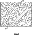
- Figure 6 illustrates a magnified view of the networked ceramic nanofibers 88.
- the nanofibers 88 are elongated, randomly oriented filaments that have a maximum diameter of 1 nanometer to 500 nanometers. More typically, the diameter will be 1 nanometer to 250 nanometers, 1 nanometer to 100 nanometers, or 1 nanometer to 50 nanometers.
- the filaments are non-linear and curve or turn such that the filaments are intertwined to form a tangled porous network.
- "networked” refers to the intertwining of the fibers or filaments. Where the filaments contact each other, they may be bonded together as a result of the process used to form the patch 86.
- the nanofibers 88 are formed of a ceramic, such as an oxide.
- the ceramic is zirconium oxide.
- the zirconium oxide may be a stabilized or partially stabilized zirconia, such as yttrium stabilized zirconia or gadolinia stabilized zirconia, or a zirconate that is doped with a rare earth stabilizer, such as yttria or gadolinia.
- the patch 86 of networked ceramic nanofibers 88 fills the dimple 82 and seals the pores 72b of the ceramic barrier coating 72.
- the nanofibers 88 may also mechanically interlock with the surface roughness in the dimple 82 that results from the abrading, thereby providing good bonding between the patch 86 and the ceramic barrier coating 72.
- the pressure of the process gas may also be controlled to produce a desirable level of roughness for mechanical interaction with the nanofibers 88.
- the pores 72b in the ceramic barrier coating 72 may be prone to infiltration of debris and other material during use of the article 60 that could damage the ceramic barrier coating 72, bond coat 74, or underlying substrate 68.
- the pores 72b are also substantially perpendicular to the bond coat 74 and substrate 68, they can provide a direct path of infiltration for CMAS (calcium-magnesium-aluminosilicate) and foreign material.
- CMAS calcium-magnesium-aluminosilicate
- the networked ceramic nanofibers 88 seal the pores 72b in the dimple 82.
- the networked ceramic nanofibers 88 may infiltrate partially into the pores 72b during deposition, thereby enhancing sealing.
- the patch 86 of networked ceramic nanofibers 88 is itself porous, the networked ceramic nanofibers 88 provide a sponge-like structure of smaller pores that provides superior thermal insulation. Therefore, the patch 86 of networked ceramic nanofibers 88, even if formed of the same composition as the ceramic barrier coating 72, provides thermal sealing of the ceramic barrier coating 72. As an example based on zirconia, the patch 86 of networked ceramic nanofibers 88 may have a thermal conductivity of approximately 0.027 Watts per meter-Kelvin.
- the filaments of the networked ceramic nanofibers 88 are also flexible and strain tolerant. The flexibility of the filaments may further facilitate entrapment of foreign particles, debris, or materials, as well as act as a "bumper" to absorb impact of particles and debris.
- the patch 86 of networked ceramic nanofibers 88 thereby provides thermal and physical sealing/protection.
- networked ceramic nanofibers are not known for being produced on barrier coatings as a patch. Rather, networked ceramic nanofibers have been produced in a screen-like cage structure. As a result, use of a patch of networked ceramic nanofibers has not been suggested in combination with a ceramic barrier coating, nor have the thermal and physical sealing benefits of a patch of ceramic nanofibers been realized for protection with a ceramic barrier coating.
- the patch 86 of networked ceramic nanofibers 88 may be deposited directly into the dimple 82.
- the patch 76 of networked ceramic nanofibers 88 may be deposited by a blow-spinning process. Blow-spinning involves spraying a precursor solution through an inner nozzle while flowing a process gas from an outer concentric nozzle such that the precursor when sprayed elongates into ultra-thin filaments.
- the filaments deposit in the dimple 82 and, after further processing, are converted into the ceramic nanofibers.
- the precursor solution includes binders and salts of the constituents that will form the ceramic, such as zirconium, oxygen, and any dopants.
- An example binder includes polyvinylpyrrolidone, and example salts may include aqueous oxynitrate, nitrate, nitrite, or chloride salts of zirconium and the selected dopants, zirconyl chloride, or metal organics such as zirconium isobutoxide or isopropoxide in a solvent.
- the amounts of the constituents may be controlled in order to control the final composition of the ceramic nanofibers.
- the filaments are then thermally treated to remove binders, etc. and sinter the ceramic.
- the thermal treatment may include heating the filaments to temperatures from 800°C to 1000°C, in one embodiment of the present invention. It is during the thermal treatment that the filaments may diffuse and thereby bond together where they are in contact.
- the thermal treatment may also cause diffusion at points of contact between the nanofibers 88 and the ceramic barrier coating 72, thereby providing additional bonding.
- the thermal treatment may be conducted using an energy beam, such as a laser.
- the energy beam can be aimed to impinge on the patch 86, with minimal or no impingement on the remaining regions 84 of the ceramic barrier coating 72 adjacent the patch 86. The effects of the heating can thus be confined to the patch 86, while avoiding the expenditure of time and energy to heat the entire article 60.
- the patch 86 may project from the ceramic barrier coating 72, which generally has a continuous, smooth outer surface. If desired, as depicted in Figure 7 , the patch 86 can be polished such that it is flush with the remaining region 84 of the ceramic barrier coating 72 adjacent the patch 86, as represented at 90.
- the ceramic barrier coating 72 may define a thickness t1.
- the patch 86 may also define a maximum thickness t2, wherein the thickness t2 is less than the thickness t1.
- the thickness t2 being less than the thickness t1 is a representation that the patch 86 is not as thick as the ceramic barrier coating 72. That is, the patch 86 most typically will be a relatively small piece of material that mends a relatively small region of the coating 72.
- the ceramic barrier coating 72 thus has a locally thin portion at the dimple 82. This locally thin portion, but for the patch 86, may otherwise be prone to CMAS or foreign substance infiltration.
Landscapes
- Engineering & Computer Science (AREA)
- Chemical & Material Sciences (AREA)
- Mechanical Engineering (AREA)
- Materials Engineering (AREA)
- Organic Chemistry (AREA)
- Chemical Kinetics & Catalysis (AREA)
- Metallurgy (AREA)
- Ceramic Engineering (AREA)
- Physics & Mathematics (AREA)
- Plasma & Fusion (AREA)
- General Engineering & Computer Science (AREA)
- Structural Engineering (AREA)
- Manufacturing & Machinery (AREA)
- Inorganic Chemistry (AREA)
- Coating By Spraying Or Casting (AREA)
- Turbine Rotor Nozzle Sealing (AREA)
Abstract
Description
- Gas turbine engine components in the core gaspath may be subject to temperatures in excess of the melting temperature of the component substrate. Cooling features and barrier coatings are used to protect the substrate from these extreme temperatures. Barrier coatings are typically formed of ceramic materials, such as yttria stabilized zirconia or gadolinium zirconate. A thermally grown oxide layer is provided on the substrate as a bond coat to enhance bonding of the barrier layer on the substrate.
- A repair process according to an aspect of the present invention includes providing an article that has a substrate and a ceramic barrier coating disposed on the substrate. The ceramic barrier coating has a damaged region, and the damaged region is abraded to provide a dimple in the ceramic barrier coating. A remaining region of the ceramic barrier coating adjacent the dimple remains intact. A patch of networked ceramic nanofibers is then deposited in the dimple.
- In an embodiment of the above embodiments, the ceramic barrier coating has a porous columnar microstructure and the networked ceramic nanofibers extend into pores of the porous columnar microstructure in the dimple.
- In an embodiment of any of the above embodiments, the abrading includes spraying the damaged region with an abrasive media.
- In an embodiment of any of the above embodiments, the abrasive media includes dry ice.
- In an embodiment of any of the above embodiments, the damaged region is a spalled or worn region.
- In an embodiment of any of the above embodiments, the depositing comprised of or consists of blow-spinning and sintering.
- In an embodiment of any of the above embodiments, the sintering is comprised of or consists of heating using an energy beam.
- An embodiment of any of the above embodiments in which the method includes polishing the patch to be flat with the remaining region of the ceramic barrier coating adjacent the patch.
- In an embodiment of any of the above embodiments, the ceramic nanofibers are comprised of or consist of zirconium oxide.
- In an embodiment of any of the above embodiments, the ceramic nanofibers are comprised of or consist of a material selected from the group consisting of yttria stabilized zirconia, gadolinia zirconate, and combinations thereof, and the ceramic barrier coating is comprised of or consists of a material selected from the group consisting of yttria stabilized zirconia, gadolinia zirconate, and combinations thereof.
- In an embodiment of any of the above embodiments, the ceramic barrier coating has a thickness t1 taken at the remaining portion adjacent the damaged region, and the patch has a thickness t2 that is less than the thickness t1.
- A repair process according to an aspect of the present invention includes providing an airfoil that has a substrate and a ceramic barrier coating disposed on the substrate. The ceramic barrier coating has a damaged region, and the damaged region is abraded to provide a dimple in the ceramic barrier coating. A remaining region of the ceramic barrier coating adjacent the dimple remains intact. A patch of networked ceramic nanofibers is then deposited in the dimple.
- In an embodiment of any of the above embodiment, the abrading includes spraying the damaged region with an abrasive media.
- In an embodiment of the above embodiment, the abrasive media is comprised of or consists of dry ice.
- In an embodiment of any of the above embodiments, the damaged region is a spalled or worn region.
- In an embodiment of any of the above embodiments, the depositing is comprised of or consists of blow-spinning and sintering.
- In an embodiment of any of the above embodiments, the sintering is comprised of or consists of heating using an energy beam.
- An embodiment of any of the above embodiments in which the process includes polishing the patch to be flat with the remaining region of the ceramic barrier coating adjacent the patch.
- An aspect of the present invention comprises an article which includes a substrate and a ceramic barrier coating disposed on the substrate. The ceramic barrier coating includes a dimple, and there is a patch of networked ceramic nanofibers disposed in the dimple.
- In an embodiment of any of the above embodiments, the ceramic nanofibers are comprised of or consists of a material selected from the group consisting of yttria stabilized zirconia, gadolinia zirconate, and combinations thereof, and the ceramic barrier coating is comprised of or consists of a material selected from the group consisting of yttria stabilized zirconia, gadolinia zirconate, and combinations thereof.
- The various features and advantages of the present disclosure will become apparent to those skilled in the art from the following detailed description. The drawings that accompany the detailed description can be briefly described as follows.
-
Figure 1 illustrates an example gas turbine engine. -
Figure 2 illustrates an example article subject to repair. -
Figure 3 illustrates a view of a representative portion of the article ofFigure 2 during a repair process involving abrading the article. -
Figure 4 illustrates the article ofFigure 3 during the repair process after abrading the article. -
Figure 5 illustrates the article ofFigure 4 during the repair process involving deposition of a patch of networked ceramic nanofibers. -
Figure 6 illustrates a magnified view of networked ceramic nanofibers. -
Figure 7 illustrates the article ofFigure 5 during the repair process involving polishing the patch of networked ceramic nanofibers. -
Figure 1 schematically illustrates agas turbine engine 20. Thegas turbine engine 20 is disclosed herein as a two-spool turbofan that generally incorporates afan section 22, a compressor section 24, acombustor section 26 and aturbine section 28. Thefan section 22 drives air along a bypass flow path B in a bypass duct defined within anacelle 15, and also drives air along a core flow path C for compression and communication into thecombustor section 26 then expansion through theturbine section 28. Although depicted as a two-spool turbofan gas turbine engine in the disclosed non-limiting embodiment, it should be understood that the concepts described herein are not limited to use with two-spool turbofans as the teachings may be applied to other types of turbine engines including but not limited to three-spool architectures. - The
exemplary engine 20 generally includes alow speed spool 30 and ahigh speed spool 32 mounted for rotation about an engine central longitudinal axis A relative to an enginestatic structure 36 viaseveral bearing systems 38. It should be understood thatvarious bearing systems 38 at various locations may alternatively or additionally be provided, and the location ofbearing systems 38 may be varied as appropriate to the application. - The
low speed spool 30 generally includes aninner shaft 40 that interconnects, a first (or low) pressure compressor 44 and a first (or low)pressure turbine 46. Theinner shaft 40 is connected to thefan 42 through a speed change mechanism, which in the exemplarygas turbine engine 20 is illustrated as a gearedarchitecture 48 to drive afan 42 at a lower speed than thelow speed spool 30. Thehigh speed spool 32 includes anouter shaft 50 that interconnects a second (or high)pressure compressor 52 and a second (or high)pressure turbine 54. Acombustor 56 is arranged in theexemplary gas turbine 20 between thehigh pressure compressor 52 and thehigh pressure turbine 54. Amid-turbine frame 57 of the enginestatic structure 36 may be arranged generally between thehigh pressure turbine 54 and thelow pressure turbine 46. Themid-turbine frame 57 further supports bearingsystems 38 in theturbine section 28. Theinner shaft 40 and theouter shaft 50 are concentric and rotate viabearing systems 38 about the engine central longitudinal axis A which is collinear with their longitudinal axes. - The core airflow is compressed by the low pressure compressor 44 then the
high pressure compressor 52, mixed and burned with fuel in thecombustor 56, then expanded over thehigh pressure turbine 54 andlow pressure turbine 46. Themid-turbine frame 57 includesairfoils 59 which are in the core airflow path C. Theturbines low speed spool 30 andhigh speed spool 32 in response to the expansion. It will be appreciated that each of the positions of thefan section 22, compressor section 24,combustor section 26,turbine section 28, and fandrive gear system 48 may be varied. For example,gear system 48 may be located aft of the low pressure compressor, or aft of thecombustor section 26 or even aft ofturbine section 28, andfan 42 may be positioned forward or aft of the location ofgear system 48. - The
engine 20 in one embodiment of the present invention is a high-bypass geared aircraft engine. In a further example, theengine 20 bypass ratio is greater than about six, with an example embodiment being greater than about ten, the gearedarchitecture 48 is an epicyclic gear train, such as a planetary gear system or other gear system, with a gear reduction ratio of greater than about 2.3 and thelow pressure turbine 46 has a pressure ratio that is greater than about five. In one disclosed embodiment, theengine 20 bypass ratio is greater than about ten, the fan diameter is significantly larger than that of the low pressure compressor 44, and thelow pressure turbine 46 has a pressure ratio that is greater than about five. Thelow pressure turbine 46 pressure ratio is pressure measured prior to the inlet oflow pressure turbine 46 as related to the pressure at the outlet of thelow pressure turbine 46 prior to an exhaust nozzle. The gearedarchitecture 48 may be an epicycle gear train, such as a planetary gear system or other gear system, with a gear reduction ratio of greater than about 2.3:1 and less than about 5:1. It should be understood, however, that the above parameters are only exemplary of one embodiment of a geared architecture engine and that the present invention is applicable to other gas turbine engines including but not limited to direct drive turbofans. - A significant amount of thrust is provided by the bypass flow B due to the high bypass ratio. The
fan section 22 of theengine 20 is designed for a particular flight condition -- typically cruise at about 0.8 Mach and about 35,000 feet (10,668 meters). The flight condition of 0.8 Mach and 35,000 ft (10,668 meters), with the engine at its best fuel consumption - also known as "bucket cruise Thrust Specific Fuel Consumption ('TSFC')" - is the industry standard parameter of lbm of fuel being burned divided by lbf of thrust the engine produces at that minimum point. "Low fan pressure ratio" is the pressure ratio across the fan blade alone, without a Fan Exit Guide Vane ("FEGV") system. The low fan pressure ratio as disclosed herein according to one non-limiting embodiment is less than about 1.45. "Low corrected fan tip speed" is the actual fan tip speed in ft/sec divided by an industry standard temperature correction of [(Tram °R) / (518.7 °R)]^0.5 (where °R = K x 9/5). The "Low corrected fan tip speed" as disclosed herein according to one non-limiting embodiment is less than about 1150 ft / second (350.5 meters/second). -
Figure 2 illustrates anarticle 60 according to an embodiment of the present invention. Thearticle 60 is a rotatable turbine blade of the engine 20 (see alsoFigure 1 ). It is to be understood that, although the embodiments herein may be described with reference to the turbine blade, this invention is also applicable to static turbine vanes, other types of airfoils, seals, combustors, or other gas turbine engine components. - The turbine blade generally includes a
platform 62, anairfoil section 64 that extends from theplatform 62, and aroot 66. Thearticle 60 is subjected during use to extreme temperatures in theengine 20. Thearticle 60 includes a coating system to protect against the high temperatures and environmental effects that might otherwise damage thearticle 60. The coating system may include a ceramic barrier coating. Such ceramic barrier coatings can be subject to damage during use, such as damage from spalling, erosion, or wear. From time to time and inasmuch as feasible, such articles are repaired in order to extend use. -
Figures 3, 4, and 5 depict an example repair process for a representative portion of thearticle 60. For a turbine blade, the portion may be on theplatform 62,airfoil section 64, orroot 66. As will also be appreciated, thearticle 60 may have numerous portions which are repaired in a similar manner as described below. - The
article 60 is formed of asubstrate 68 and acoating system 70. Most typically, thesubstrate 68 will be formed of a superalloy, such as a nickel- or cobalt-based alloy. Alternatively, thesubstrate 68 may be formed of a ceramic or ceramic composite material. - The
coating system 70 includes aceramic barrier coating 72 disposed on thesubstrate 68. Anoptional bond coat 74 that has a thermally grownoxide region 74a is disposed between theceramic barrier coating 72 and thesubstrate 68. Thebond coat 74 may be MCrAlY, where M is nickel, iron or cobalt, Cr is chromium, Al is aluminum, and Y is yttrium. A portion of thebond coat 74 may oxidize to form the thermally grownoxide region 74a, which facilitates bonding of theceramic barrier coating 72. - In an embodiment of the present invention, the
ceramic barrier coating 72 is formed primarily of zirconium oxide. For instance, the zirconium oxide may be a stabilized or partially stabilized zirconia, such as yttrium stabilized zirconia or gadolinia stabilized zirconia, or a zirconate that is doped with a rare earth stabilizer, such as yttria or gadolinia. Theceramic barrier coating 72 may, for example, be deposited by plasma spray or physical vapor deposition, which generally result in a porous structure. - In the illustrated embodiments, the
ceramic barrier coating 72 has a columnar microstructure, represented schematically bymicrostructural columns 72a. Such a columnar microstructure is a result of fabrication by electron beam physical vapor deposition. Thecolumns 72a are substantially perpendicular to thebond coat 74 andsubstrate 68. There arepores 72b defined by the gaps between thecolumns 72a. Such a columnar microstructure facilitates coating durability. - The repair process begins with the providing of the
article 60 for repair, where theceramic barrier coating 72 has a damagedregion 72c. The "providing" may include identifying that thearticle 60 is in need of repair. In this regard, known inspection techniques may be used to detect and assess damage. More typically however, the article for repair will have already been identified and the "providing" may refer to the selection of the article to begin the repair process. - The damaged
region 72c may be a region of theceramic barrier coating 72 which has a physical deformity or imperfection, especially to a point or degree that is unacceptable for the givenarticle 60. Most typically, the damagedregion 72c will be the result of physical phenomena that are incurred during use of thearticle 60 in its intended operating environment. As an example, the phenomena may be related to thermal-mechanical stresses that cause spallation, impact events that cause erosion, rubbing events that cause wear, or combinations of these. In these regards, the physical deformity may be a spalled, eroded, and/or worn portion of theceramic barrier coating 72. Alternatively, damage may be incurred prior to use or outside of use, such as during handling and transport of thearticle 60. In the illustrated example, the physical deformity is adepression 76 in theceramic barrier coating 72. In another alternative, the physical deformity may be an imperfection, such as a crack or void, that results from original fabrication of theceramic barrier coating 72. For instance, a fabrication imperfection that renders thearticle 60 unacceptable for its intended use may be repaired using the repair process of the present invention to render the article acceptable for its intended use. - The next step in the repair process includes abrading the damaged
region 72c. Thedepression 76 may contain debris or other undesirable substances which could be detrimental to theceramic barrier coating 72 or hinder the remainder of the repair process. In this respect, the abrading facilitates removal of much or all of the debris, as well as possibly small portions of theceramic barrier coating 72 in the vicinity of the damagedregion 72c. The abrading thereby produces a fresh, clean surface in theceramic barrier coating 72. - As an example, the abrading may include spraying an
abrasive media 78 from aspray nozzle 80 onto the damagedregion 72c. For instance, theabrasive media 78 may be carried in a pressurized process gas. Theabrasive media 78 strikes the damagedregion 72c and thereby removes the debris and possibly a portion of theceramic barrier coating 72. The pressure of the process gas may be controlled in order to control removal of the debris andceramic barrier coating 72. In one embodiment, theabrasive media 78 includes particles of dry ice, which is solid carbon dioxide. The dry ice facilitates clean removal because it is substantially nonreactive at normal pressure and temperature (NTP) with theceramic barrier coating 72 and thus does not leave residue or stains. Additionally, the dry ice rapidly evaporates and thus does not leave a mess. -
Figure 4 depicts thearticle 60 after the abrading. The abrading has removed debris and a portion of theceramic barrier coating 72 such that adimple 82 remains in theceramic barrier coating 72. A remaining region of the ceramic barrier coating, a representative portion of which is shown at 84, adjacent thedimple 82, remains intact after the abrading step. For instance, "intact" may refer to this region as being unchanged in physical character before and after the abrading. In this example, thedimple 82 is only modestly larger than the damagedregion 72c and does not extend entirely through the thickness of theceramic barrier coating 72. - The next step in the repair process, depicted in
Figure 5 , is the deposition of apatch 86 into thedimple 82. Thepatch 86 is composed of networkedceramic nanofibers 88.Figure 6 illustrates a magnified view of the networkedceramic nanofibers 88. Thenanofibers 88 are elongated, randomly oriented filaments that have a maximum diameter of 1 nanometer to 500 nanometers. More typically, the diameter will be 1 nanometer to 250 nanometers, 1 nanometer to 100 nanometers, or 1 nanometer to 50 nanometers. The filaments are non-linear and curve or turn such that the filaments are intertwined to form a tangled porous network. As used herein, "networked" refers to the intertwining of the fibers or filaments. Where the filaments contact each other, they may be bonded together as a result of the process used to form thepatch 86. - The
nanofibers 88 are formed of a ceramic, such as an oxide. In one example, the ceramic is zirconium oxide. For instance, the zirconium oxide may be a stabilized or partially stabilized zirconia, such as yttrium stabilized zirconia or gadolinia stabilized zirconia, or a zirconate that is doped with a rare earth stabilizer, such as yttria or gadolinia. - The
patch 86 of networkedceramic nanofibers 88 fills thedimple 82 and seals thepores 72b of theceramic barrier coating 72. Thenanofibers 88 may also mechanically interlock with the surface roughness in thedimple 82 that results from the abrading, thereby providing good bonding between thepatch 86 and theceramic barrier coating 72. In that regard, the pressure of the process gas may also be controlled to produce a desirable level of roughness for mechanical interaction with thenanofibers 88. - The
pores 72b in theceramic barrier coating 72 may be prone to infiltration of debris and other material during use of thearticle 60 that could damage theceramic barrier coating 72,bond coat 74, orunderlying substrate 68. In particular, since thepores 72b are also substantially perpendicular to thebond coat 74 andsubstrate 68, they can provide a direct path of infiltration for CMAS (calcium-magnesium-aluminosilicate) and foreign material. In this regard, the networkedceramic nanofibers 88 seal thepores 72b in thedimple 82. As an example, the networkedceramic nanofibers 88 may infiltrate partially into thepores 72b during deposition, thereby enhancing sealing. - Although the
patch 86 of networkedceramic nanofibers 88 is itself porous, the networkedceramic nanofibers 88 provide a sponge-like structure of smaller pores that provides superior thermal insulation. Therefore, thepatch 86 of networkedceramic nanofibers 88, even if formed of the same composition as theceramic barrier coating 72, provides thermal sealing of theceramic barrier coating 72. As an example based on zirconia, thepatch 86 of networkedceramic nanofibers 88 may have a thermal conductivity of approximately 0.027 Watts per meter-Kelvin. - Additionally, the filaments of the networked
ceramic nanofibers 88 are also flexible and strain tolerant. The flexibility of the filaments may further facilitate entrapment of foreign particles, debris, or materials, as well as act as a "bumper" to absorb impact of particles and debris. Thepatch 86 of networkedceramic nanofibers 88 thereby provides thermal and physical sealing/protection. - It is noted that networked ceramic nanofibers are not known for being produced on barrier coatings as a patch. Rather, networked ceramic nanofibers have been produced in a screen-like cage structure. As a result, use of a patch of networked ceramic nanofibers has not been suggested in combination with a ceramic barrier coating, nor have the thermal and physical sealing benefits of a patch of ceramic nanofibers been realized for protection with a ceramic barrier coating.
- The
patch 86 of networkedceramic nanofibers 88 may be deposited directly into thedimple 82. For example, thepatch 76 of networkedceramic nanofibers 88 may be deposited by a blow-spinning process. Blow-spinning involves spraying a precursor solution through an inner nozzle while flowing a process gas from an outer concentric nozzle such that the precursor when sprayed elongates into ultra-thin filaments. The filaments deposit in thedimple 82 and, after further processing, are converted into the ceramic nanofibers. The precursor solution includes binders and salts of the constituents that will form the ceramic, such as zirconium, oxygen, and any dopants. An example binder includes polyvinylpyrrolidone, and example salts may include aqueous oxynitrate, nitrate, nitrite, or chloride salts of zirconium and the selected dopants, zirconyl chloride, or metal organics such as zirconium isobutoxide or isopropoxide in a solvent. The amounts of the constituents may be controlled in order to control the final composition of the ceramic nanofibers. After spinning, the filaments are then thermally treated to remove binders, etc. and sinter the ceramic. The thermal treatment may include heating the filaments to temperatures from 800°C to 1000°C, in one embodiment of the present invention. It is during the thermal treatment that the filaments may diffuse and thereby bond together where they are in contact. The thermal treatment may also cause diffusion at points of contact between thenanofibers 88 and theceramic barrier coating 72, thereby providing additional bonding. - In an alternative embodiment,, the thermal treatment may be conducted using an energy beam, such as a laser. In particular, the energy beam can be aimed to impinge on the
patch 86, with minimal or no impingement on the remainingregions 84 of theceramic barrier coating 72 adjacent thepatch 86. The effects of the heating can thus be confined to thepatch 86, while avoiding the expenditure of time and energy to heat theentire article 60. - After deposition, the
patch 86 may project from theceramic barrier coating 72, which generally has a continuous, smooth outer surface. If desired, as depicted inFigure 7 , thepatch 86 can be polished such that it is flush with the remainingregion 84 of theceramic barrier coating 72 adjacent thepatch 86, as represented at 90. - At the remaining
region 84, theceramic barrier coating 72 may define a thickness t1. Thepatch 86 may also define a maximum thickness t2, wherein the thickness t2 is less than the thickness t1. The thickness t2 being less than the thickness t1 is a representation that thepatch 86 is not as thick as theceramic barrier coating 72. That is, thepatch 86 most typically will be a relatively small piece of material that mends a relatively small region of thecoating 72. In particular, theceramic barrier coating 72 thus has a locally thin portion at thedimple 82. This locally thin portion, but for thepatch 86, may otherwise be prone to CMAS or foreign substance infiltration. - Although a combination of features is shown in the illustrated embodiment of the present invention, not all of them need to be combined to realize the benefits of various embodiments of this invention. In other words, a system designed according to an embodiment of this invention will not necessarily include all of the features shown in any one of the Figures or all of the portions schematically shown in the Figures. Moreover, selected features of one embodiment may be combined with selected features of other embodiments.
- The preceding description is exemplary rather than limiting in nature. Variations and modifications to the disclosed examples may become apparent to those skilled in the art that do not necessarily depart from this disclosure. The scope of legal protection given to this disclosure can only be determined by studying the following claims.
Claims (15)
- A repair process comprising:providing an article (60) that has a substrate (68) and a ceramic barrier coating (70) disposed on the substrate (68), wherein the ceramic barrier coating (70) has a damaged region (72c);abrading the damaged region (72c) to provide a dimple (82) in the ceramic barrier coating (70), wherein a remaining region (84) of the ceramic barrier coating (70) adjacent the dimple (82) remains intact; anddepositing a patch (86) of networked ceramic nanofibers (88) in the dimple (82).
- The process as recited in claim 1, wherein the ceramic barrier coating (70) has a porous columnar microstructure and the networked ceramic nanofibers (88) extend into pores (72b) of the porous columnar microstructure in the dimple (82).
- The process as recited in claim 1 or 2, wherein the abrading includes spraying the damaged region (72c) with an abrasive media (78) and, optionally, the abrasive media (78) is comprised of or consists of dry ice.
- The process as recited in any of claims 1 to 3, wherein the damaged region is a spalled or worn region.
- The process as recited any of in claims 1 to 4, wherein the depositing is comprised of or consists of blow-spinning and sintering and, optionally, the sintering is comprised of or consists of heating using an energy beam.
- The process as recited in any of claims 1 to 5, further comprising polishing the patch (86) to be flat with the remaining region (84) of the ceramic barrier (70) coating adjacent the patch (86).
- The process as recited in any of claims 1 to 6, wherein the ceramic nanofibers (88) are comprised of or consist of zirconium oxide.
- The process as recited in any of claims 1 to 7, wherein the ceramic nanofibers (88) are comprised of or consist of a material selected from the group consisting of yttria stabilized zirconia, gadolinia zirconate, and combinations thereof, and the ceramic barrier coating (70) is comprised of or consists of a material selected from the group consisting of yttria stabilized zirconia, gadolinia zirconate, and combinations thereof.
- The process as recited in any of claims 1 to 8, wherein the ceramic barrier coating (70) has a thickness t1 taken at the remaining portion (84) adjacent the damaged region, and the patch (86) has a thickness t2 that is less than the thickness t1.
- A repair process comprising:providing an airfoil (60) that has a substrate (68) and a ceramic barrier coating (70) disposed on the substrate, wherein the ceramic barrier coating has a damaged region (72c);abrading the damaged region (72c) to provide a dimple (82) in the ceramic barrier coating (70), wherein a remaining region (84) of the ceramic barrier coating (70) adjacent the dimple (82) remains intact; anddepositing a patch (86) of networked ceramic nanofibers (88) in the dimple (82).
- The process as recited in claim 10, wherein the abrading includes spraying the damaged region with an abrasive media (78) and, optionally, the abrasive media (78) is comprised of or consists of dry ice.
- The process as recited in claim 10 or 11, wherein the damaged region (72a) is a spalled or worn region.
- The process as recited in any of claims 10 to 12, wherein the depositing is comprised of or consists of blow-spinning and sintering and optionally, the sintering is comprised of or consists of heating using an energy beam.
- The process as recited in any of claims 10 to 13, further comprising polishing the patch (86) to be flat with the remaining region (84) of the ceramic barrier coating (70) adjacent the patch (86).
- An article (60) comprising:a substrate (68);a ceramic barrier coating (70) disposed on the substrate (68), the ceramic barrier coating (70) including a dimple (82); anda patch (86) of networked ceramic nanofibers (88) disposed in the dimple (82) and, optionally, the ceramic nanofibers (88) are comprised of or consist of a material selected from the group consisting of yttria stabilized zirconia, gadolinia zirconate, and combinations thereof, and the ceramic barrier coating (70) is comprised of or consists of a material selected from the group consisting of yttria stabilized zirconia, gadolinia zirconate, and combinations thereof.
Applications Claiming Priority (1)
| Application Number | Priority Date | Filing Date | Title |
|---|---|---|---|
| US16/270,660 US10919180B2 (en) | 2019-02-08 | 2019-02-08 | Repair process using networked ceramic nanofibers |
Publications (2)
| Publication Number | Publication Date |
|---|---|
| EP3693488A1 true EP3693488A1 (en) | 2020-08-12 |
| EP3693488B1 EP3693488B1 (en) | 2024-10-16 |
Family
ID=69570545
Family Applications (1)
| Application Number | Title | Priority Date | Filing Date |
|---|---|---|---|
| EP20156401.0A Active EP3693488B1 (en) | 2019-02-08 | 2020-02-10 | Repair process of a core gas-path gas turbine using networked ceramic nanofibers |
Country Status (2)
| Country | Link |
|---|---|
| US (2) | US10919180B2 (en) |
| EP (1) | EP3693488B1 (en) |
Families Citing this family (3)
| Publication number | Priority date | Publication date | Assignee | Title |
|---|---|---|---|---|
| US12319834B2 (en) | 2021-12-17 | 2025-06-03 | General Electric Company | Anti-corrosion material and application method |
| US12394804B2 (en) | 2022-08-16 | 2025-08-19 | General Electric Company | Thermal management of a fuel cell assembly |
| CN116618952B (en) * | 2023-05-19 | 2025-12-16 | 中国人民解放军空军工程大学航空机务士官学校 | Quick repair method for damage to casing of helicopter reducer through Kong Zhan |
Citations (2)
| Publication number | Priority date | Publication date | Assignee | Title |
|---|---|---|---|---|
| EP2236648A1 (en) * | 2009-03-30 | 2010-10-06 | Alstom Technology Ltd | Comprehensive method for local application and local repair of thermal barrier coatings |
| CN108754495A (en) * | 2018-06-25 | 2018-11-06 | 广东省新材料研究所 | A kind of composite thermal barrier coating and the preparation method and application thereof |
Family Cites Families (4)
| Publication number | Priority date | Publication date | Assignee | Title |
|---|---|---|---|---|
| US5723078A (en) * | 1996-05-24 | 1998-03-03 | General Electric Company | Method for repairing a thermal barrier coating |
| US7842335B2 (en) | 2004-04-07 | 2010-11-30 | General Electric Company | Field repairable high temperature smooth wear coating |
| EP2317079B1 (en) | 2009-10-30 | 2020-05-20 | Ansaldo Energia Switzerland AG | Abradable coating system |
| US11591918B2 (en) * | 2019-02-08 | 2023-02-28 | Raytheon Technologies Corporation | Article with ceramic barrier coating and layer of networked ceramic nanofibers |
-
2019
- 2019-02-08 US US16/270,660 patent/US10919180B2/en active Active
-
2020
- 2020-02-10 EP EP20156401.0A patent/EP3693488B1/en active Active
-
2021
- 2021-02-12 US US17/174,842 patent/US12076885B2/en active Active
Patent Citations (2)
| Publication number | Priority date | Publication date | Assignee | Title |
|---|---|---|---|---|
| EP2236648A1 (en) * | 2009-03-30 | 2010-10-06 | Alstom Technology Ltd | Comprehensive method for local application and local repair of thermal barrier coatings |
| CN108754495A (en) * | 2018-06-25 | 2018-11-06 | 广东省新材料研究所 | A kind of composite thermal barrier coating and the preparation method and application thereof |
Non-Patent Citations (1)
| Title |
|---|
| AZAD ABDUL-MAJEED: "Fabrication of yttria-stabilized zirconia nanofibers by electrospinning", MATERIALS LETTERS, vol. 60, no. 1, 18 August 2005 (2005-08-18), pages 67 - 72, XP029235035, ISSN: 0167-577X, DOI: 10.1016/J.MATLET.2005.07.085 * |
Also Published As
| Publication number | Publication date |
|---|---|
| US10919180B2 (en) | 2021-02-16 |
| EP3693488B1 (en) | 2024-10-16 |
| US20210162624A1 (en) | 2021-06-03 |
| US20200254648A1 (en) | 2020-08-13 |
| US12076885B2 (en) | 2024-09-03 |
Similar Documents
| Publication | Publication Date | Title |
|---|---|---|
| US10458256B2 (en) | Thermal-sprayed bonding of a ceramic structure to a substrate | |
| US10794211B2 (en) | Seal geometries for reduced leakage in gas turbines and methods of forming | |
| US12076885B2 (en) | Repair process using networked ceramic nanofibers | |
| EP3640360B1 (en) | Method of manufacturing a geometrically segmented abradable ceramic thermal barrier coating with improved spallation resistance | |
| JP2006036632A (en) | 7FA + e first stage abradable coating and method for producing the same | |
| US11781486B2 (en) | Ceramic component having silicon layer and barrier layer | |
| US10570765B2 (en) | Endwall arc segments with cover across joint | |
| EP3196419A1 (en) | Blade outer air seal having surface layer with pockets | |
| US9022743B2 (en) | Segmented thermally insulating coating | |
| EP4119773A1 (en) | Seal system having silicon layer and barrier layer | |
| US11591918B2 (en) | Article with ceramic barrier coating and layer of networked ceramic nanofibers | |
| US10480334B2 (en) | Airfoil with geometrically segmented coating section | |
| US11306600B2 (en) | Enhanced adhesion thermal barrier coating | |
| US10309238B2 (en) | Turbine engine component with geometrically segmented coating section and cooling passage | |
| US11274828B2 (en) | Article with bond coat layer and layer of networked ceramic nanofibers | |
| EP3421729B1 (en) | Alumina seal coating with interlayer | |
| US12617734B2 (en) | Ceramic matrix composite article and method of making the same | |
| US20240043350A1 (en) | Ceramic matrix composite article and method of making the same | |
| EP3556998B1 (en) | Air seal having gaspath portion with geometrically segmented coating |
Legal Events
| Date | Code | Title | Description |
|---|---|---|---|
| PUAI | Public reference made under article 153(3) epc to a published international application that has entered the european phase |
Free format text: ORIGINAL CODE: 0009012 |
|
| STAA | Information on the status of an ep patent application or granted ep patent |
Free format text: STATUS: THE APPLICATION HAS BEEN PUBLISHED |
|
| AK | Designated contracting states |
Kind code of ref document: A1 Designated state(s): AL AT BE BG CH CY CZ DE DK EE ES FI FR GB GR HR HU IE IS IT LI LT LU LV MC MK MT NL NO PL PT RO RS SE SI SK SM TR |
|
| AX | Request for extension of the european patent |
Extension state: BA ME |
|
| STAA | Information on the status of an ep patent application or granted ep patent |
Free format text: STATUS: REQUEST FOR EXAMINATION WAS MADE |
|
| 17P | Request for examination filed |
Effective date: 20210212 |
|
| RAP1 | Party data changed (applicant data changed or rights of an application transferred) |
Owner name: RAYTHEON TECHNOLOGIES CORPORATION |
|
| RBV | Designated contracting states (corrected) |
Designated state(s): AL AT BE BG CH CY CZ DE DK EE ES FI FR GB GR HR HU IE IS IT LI LT LU LV MC MK MT NL NO PL PT RO RS SE SI SK SM TR |
|
| STAA | Information on the status of an ep patent application or granted ep patent |
Free format text: STATUS: EXAMINATION IS IN PROGRESS |
|
| 17Q | First examination report despatched |
Effective date: 20230124 |
|
| RAP3 | Party data changed (applicant data changed or rights of an application transferred) |
Owner name: RTX CORPORATION |
|
| GRAP | Despatch of communication of intention to grant a patent |
Free format text: ORIGINAL CODE: EPIDOSNIGR1 |
|
| RIC1 | Information provided on ipc code assigned before grant |
Ipc: F01D 5/28 20060101ALI20240411BHEP Ipc: C23C 4/18 20060101ALI20240411BHEP Ipc: F01D 5/00 20060101ALI20240411BHEP Ipc: C23C 4/11 20160101ALI20240411BHEP Ipc: C23C 4/10 20160101ALI20240411BHEP Ipc: C23C 4/02 20060101AFI20240411BHEP |
|
| STAA | Information on the status of an ep patent application or granted ep patent |
Free format text: STATUS: GRANT OF PATENT IS INTENDED |
|
| INTG | Intention to grant announced |
Effective date: 20240516 |
|
| GRAS | Grant fee paid |
Free format text: ORIGINAL CODE: EPIDOSNIGR3 |
|
| GRAA | (expected) grant |
Free format text: ORIGINAL CODE: 0009210 |
|
| STAA | Information on the status of an ep patent application or granted ep patent |
Free format text: STATUS: THE PATENT HAS BEEN GRANTED |
|
| AK | Designated contracting states |
Kind code of ref document: B1 Designated state(s): AL AT BE BG CH CY CZ DE DK EE ES FI FR GB GR HR HU IE IS IT LI LT LU LV MC MK MT NL NO PL PT RO RS SE SI SK SM TR |
|
| REG | Reference to a national code |
Ref country code: GB Ref legal event code: FG4D |
|
| REG | Reference to a national code |
Ref country code: CH Ref legal event code: EP |
|
| REG | Reference to a national code |
Ref country code: IE Ref legal event code: FG4D |
|
| REG | Reference to a national code |
Ref country code: DE Ref legal event code: R096 Ref document number: 602020039405 Country of ref document: DE |
|
| REG | Reference to a national code |
Ref country code: LT Ref legal event code: MG9D |
|
| REG | Reference to a national code |
Ref country code: NL Ref legal event code: MP Effective date: 20241016 |
|
| REG | Reference to a national code |
Ref country code: AT Ref legal event code: MK05 Ref document number: 1732980 Country of ref document: AT Kind code of ref document: T Effective date: 20241016 |
|
| PG25 | Lapsed in a contracting state [announced via postgrant information from national office to epo] |
Ref country code: NL Free format text: LAPSE BECAUSE OF FAILURE TO SUBMIT A TRANSLATION OF THE DESCRIPTION OR TO PAY THE FEE WITHIN THE PRESCRIBED TIME-LIMIT Effective date: 20241016 |
|
| PG25 | Lapsed in a contracting state [announced via postgrant information from national office to epo] |
Ref country code: NL Free format text: LAPSE BECAUSE OF FAILURE TO SUBMIT A TRANSLATION OF THE DESCRIPTION OR TO PAY THE FEE WITHIN THE PRESCRIBED TIME-LIMIT Effective date: 20241016 |
|
| PG25 | Lapsed in a contracting state [announced via postgrant information from national office to epo] |
Ref country code: PT Free format text: LAPSE BECAUSE OF FAILURE TO SUBMIT A TRANSLATION OF THE DESCRIPTION OR TO PAY THE FEE WITHIN THE PRESCRIBED TIME-LIMIT Effective date: 20250217 Ref country code: HR Free format text: LAPSE BECAUSE OF FAILURE TO SUBMIT A TRANSLATION OF THE DESCRIPTION OR TO PAY THE FEE WITHIN THE PRESCRIBED TIME-LIMIT Effective date: 20241016 Ref country code: IS Free format text: LAPSE BECAUSE OF FAILURE TO SUBMIT A TRANSLATION OF THE DESCRIPTION OR TO PAY THE FEE WITHIN THE PRESCRIBED TIME-LIMIT Effective date: 20250216 |
|
| PG25 | Lapsed in a contracting state [announced via postgrant information from national office to epo] |
Ref country code: FI Free format text: LAPSE BECAUSE OF FAILURE TO SUBMIT A TRANSLATION OF THE DESCRIPTION OR TO PAY THE FEE WITHIN THE PRESCRIBED TIME-LIMIT Effective date: 20241016 |
|
| PG25 | Lapsed in a contracting state [announced via postgrant information from national office to epo] |
Ref country code: BG Free format text: LAPSE BECAUSE OF FAILURE TO SUBMIT A TRANSLATION OF THE DESCRIPTION OR TO PAY THE FEE WITHIN THE PRESCRIBED TIME-LIMIT Effective date: 20241016 |
|
| PG25 | Lapsed in a contracting state [announced via postgrant information from national office to epo] |
Ref country code: ES Free format text: LAPSE BECAUSE OF FAILURE TO SUBMIT A TRANSLATION OF THE DESCRIPTION OR TO PAY THE FEE WITHIN THE PRESCRIBED TIME-LIMIT Effective date: 20241016 |
|
| PG25 | Lapsed in a contracting state [announced via postgrant information from national office to epo] |
Ref country code: NO Free format text: LAPSE BECAUSE OF FAILURE TO SUBMIT A TRANSLATION OF THE DESCRIPTION OR TO PAY THE FEE WITHIN THE PRESCRIBED TIME-LIMIT Effective date: 20250116 |
|
| PG25 | Lapsed in a contracting state [announced via postgrant information from national office to epo] |
Ref country code: LV Free format text: LAPSE BECAUSE OF FAILURE TO SUBMIT A TRANSLATION OF THE DESCRIPTION OR TO PAY THE FEE WITHIN THE PRESCRIBED TIME-LIMIT Effective date: 20241016 Ref country code: AT Free format text: LAPSE BECAUSE OF FAILURE TO SUBMIT A TRANSLATION OF THE DESCRIPTION OR TO PAY THE FEE WITHIN THE PRESCRIBED TIME-LIMIT Effective date: 20241016 Ref country code: GR Free format text: LAPSE BECAUSE OF FAILURE TO SUBMIT A TRANSLATION OF THE DESCRIPTION OR TO PAY THE FEE WITHIN THE PRESCRIBED TIME-LIMIT Effective date: 20250117 |
|
| PG25 | Lapsed in a contracting state [announced via postgrant information from national office to epo] |
Ref country code: PL Free format text: LAPSE BECAUSE OF FAILURE TO SUBMIT A TRANSLATION OF THE DESCRIPTION OR TO PAY THE FEE WITHIN THE PRESCRIBED TIME-LIMIT Effective date: 20241016 |
|
| PG25 | Lapsed in a contracting state [announced via postgrant information from national office to epo] |
Ref country code: RS Free format text: LAPSE BECAUSE OF FAILURE TO SUBMIT A TRANSLATION OF THE DESCRIPTION OR TO PAY THE FEE WITHIN THE PRESCRIBED TIME-LIMIT Effective date: 20250116 |
|
| PG25 | Lapsed in a contracting state [announced via postgrant information from national office to epo] |
Ref country code: SM Free format text: LAPSE BECAUSE OF FAILURE TO SUBMIT A TRANSLATION OF THE DESCRIPTION OR TO PAY THE FEE WITHIN THE PRESCRIBED TIME-LIMIT Effective date: 20241016 |
|
| PG25 | Lapsed in a contracting state [announced via postgrant information from national office to epo] |
Ref country code: DK Free format text: LAPSE BECAUSE OF FAILURE TO SUBMIT A TRANSLATION OF THE DESCRIPTION OR TO PAY THE FEE WITHIN THE PRESCRIBED TIME-LIMIT Effective date: 20241016 |
|
| REG | Reference to a national code |
Ref country code: DE Ref legal event code: R097 Ref document number: 602020039405 Country of ref document: DE |
|
| PG25 | Lapsed in a contracting state [announced via postgrant information from national office to epo] |
Ref country code: EE Free format text: LAPSE BECAUSE OF FAILURE TO SUBMIT A TRANSLATION OF THE DESCRIPTION OR TO PAY THE FEE WITHIN THE PRESCRIBED TIME-LIMIT Effective date: 20241016 |
|
| PG25 | Lapsed in a contracting state [announced via postgrant information from national office to epo] |
Ref country code: RO Free format text: LAPSE BECAUSE OF FAILURE TO SUBMIT A TRANSLATION OF THE DESCRIPTION OR TO PAY THE FEE WITHIN THE PRESCRIBED TIME-LIMIT Effective date: 20241016 |
|
| PG25 | Lapsed in a contracting state [announced via postgrant information from national office to epo] |
Ref country code: SK Free format text: LAPSE BECAUSE OF FAILURE TO SUBMIT A TRANSLATION OF THE DESCRIPTION OR TO PAY THE FEE WITHIN THE PRESCRIBED TIME-LIMIT Effective date: 20241016 |
|
| PG25 | Lapsed in a contracting state [announced via postgrant information from national office to epo] |
Ref country code: CZ Free format text: LAPSE BECAUSE OF FAILURE TO SUBMIT A TRANSLATION OF THE DESCRIPTION OR TO PAY THE FEE WITHIN THE PRESCRIBED TIME-LIMIT Effective date: 20241016 |
|
| PG25 | Lapsed in a contracting state [announced via postgrant information from national office to epo] |
Ref country code: IT Free format text: LAPSE BECAUSE OF FAILURE TO SUBMIT A TRANSLATION OF THE DESCRIPTION OR TO PAY THE FEE WITHIN THE PRESCRIBED TIME-LIMIT Effective date: 20241016 |
|
| PLBE | No opposition filed within time limit |
Free format text: ORIGINAL CODE: 0009261 |
|
| STAA | Information on the status of an ep patent application or granted ep patent |
Free format text: STATUS: NO OPPOSITION FILED WITHIN TIME LIMIT |
|
| PG25 | Lapsed in a contracting state [announced via postgrant information from national office to epo] |
Ref country code: SE Free format text: LAPSE BECAUSE OF FAILURE TO SUBMIT A TRANSLATION OF THE DESCRIPTION OR TO PAY THE FEE WITHIN THE PRESCRIBED TIME-LIMIT Effective date: 20241016 |
|
| PG25 | Lapsed in a contracting state [announced via postgrant information from national office to epo] |
Ref country code: MC Free format text: LAPSE BECAUSE OF FAILURE TO SUBMIT A TRANSLATION OF THE DESCRIPTION OR TO PAY THE FEE WITHIN THE PRESCRIBED TIME-LIMIT Effective date: 20241016 |
|
| 26N | No opposition filed |
Effective date: 20250717 |
|
| REG | Reference to a national code |
Ref country code: CH Ref legal event code: PL |
|
| PG25 | Lapsed in a contracting state [announced via postgrant information from national office to epo] |
Ref country code: LU Free format text: LAPSE BECAUSE OF NON-PAYMENT OF DUE FEES Effective date: 20250210 |
|
| PG25 | Lapsed in a contracting state [announced via postgrant information from national office to epo] |
Ref country code: CH Free format text: LAPSE BECAUSE OF NON-PAYMENT OF DUE FEES Effective date: 20250228 |
|
| REG | Reference to a national code |
Ref country code: BE Ref legal event code: MM Effective date: 20250228 |
|
| PG25 | Lapsed in a contracting state [announced via postgrant information from national office to epo] |
Ref country code: BE Free format text: LAPSE BECAUSE OF NON-PAYMENT OF DUE FEES Effective date: 20250228 |
|
| PG25 | Lapsed in a contracting state [announced via postgrant information from national office to epo] |
Ref country code: IE Free format text: LAPSE BECAUSE OF NON-PAYMENT OF DUE FEES Effective date: 20250210 |
|
| PGFP | Annual fee paid to national office [announced via postgrant information from national office to epo] |
Ref country code: GB Payment date: 20260121 Year of fee payment: 7 |
|
| PGFP | Annual fee paid to national office [announced via postgrant information from national office to epo] |
Ref country code: DE Payment date: 20260121 Year of fee payment: 7 |
|
| PGFP | Annual fee paid to national office [announced via postgrant information from national office to epo] |
Ref country code: FR Payment date: 20260121 Year of fee payment: 7 |