EP3693285A1 - Package assembly and method for producing the package assembly - Google Patents
Package assembly and method for producing the package assembly Download PDFInfo
- Publication number
- EP3693285A1 EP3693285A1 EP20154348.5A EP20154348A EP3693285A1 EP 3693285 A1 EP3693285 A1 EP 3693285A1 EP 20154348 A EP20154348 A EP 20154348A EP 3693285 A1 EP3693285 A1 EP 3693285A1
- Authority
- EP
- European Patent Office
- Prior art keywords
- package
- section
- exoskeleton
- attached
- rear section
- Prior art date
- Legal status (The legal status is an assumption and is not a legal conclusion. Google has not performed a legal analysis and makes no representation as to the accuracy of the status listed.)
- Granted
Links
Images




Classifications
-
- B—PERFORMING OPERATIONS; TRANSPORTING
- B65—CONVEYING; PACKING; STORING; HANDLING THIN OR FILAMENTARY MATERIAL
- B65D—CONTAINERS FOR STORAGE OR TRANSPORT OF ARTICLES OR MATERIALS, e.g. BAGS, BARRELS, BOTTLES, BOXES, CANS, CARTONS, CRATES, DRUMS, JARS, TANKS, HOPPERS, FORWARDING CONTAINERS; ACCESSORIES, CLOSURES, OR FITTINGS THEREFOR; PACKAGING ELEMENTS; PACKAGES
- B65D71/00—Bundles of articles held together by packaging elements for convenience of storage or transport, e.g. portable segregating carrier for plural receptacles such as beer cans or pop bottles; Bales of material
- B65D71/0085—Packaging elements adhered to the articles, e.g. a carton sheet
-
- B—PERFORMING OPERATIONS; TRANSPORTING
- B65—CONVEYING; PACKING; STORING; HANDLING THIN OR FILAMENTARY MATERIAL
- B65D—CONTAINERS FOR STORAGE OR TRANSPORT OF ARTICLES OR MATERIALS, e.g. BAGS, BARRELS, BOTTLES, BOXES, CANS, CARTONS, CRATES, DRUMS, JARS, TANKS, HOPPERS, FORWARDING CONTAINERS; ACCESSORIES, CLOSURES, OR FITTINGS THEREFOR; PACKAGING ELEMENTS; PACKAGES
- B65D5/00—Rigid or semi-rigid containers of polygonal cross-section, e.g. boxes, cartons or trays, formed by folding or erecting one or more blanks made of paper
- B65D5/42—Details of containers or of foldable or erectable container blanks
- B65D5/44—Integral, inserted or attached portions forming internal or external fittings
- B65D5/441—Reinforcements
- B65D5/445—Reinforcements formed separately from the container
-
- B—PERFORMING OPERATIONS; TRANSPORTING
- B65—CONVEYING; PACKING; STORING; HANDLING THIN OR FILAMENTARY MATERIAL
- B65D—CONTAINERS FOR STORAGE OR TRANSPORT OF ARTICLES OR MATERIALS, e.g. BAGS, BARRELS, BOTTLES, BOXES, CANS, CARTONS, CRATES, DRUMS, JARS, TANKS, HOPPERS, FORWARDING CONTAINERS; ACCESSORIES, CLOSURES, OR FITTINGS THEREFOR; PACKAGING ELEMENTS; PACKAGES
- B65D5/00—Rigid or semi-rigid containers of polygonal cross-section, e.g. boxes, cartons or trays, formed by folding or erecting one or more blanks made of paper
- B65D5/42—Details of containers or of foldable or erectable container blanks
- B65D5/72—Contents-dispensing means
- B65D5/74—Spouts
- B65D5/746—Spouts formed separately from the container
-
- B—PERFORMING OPERATIONS; TRANSPORTING
- B65—CONVEYING; PACKING; STORING; HANDLING THIN OR FILAMENTARY MATERIAL
- B65D—CONTAINERS FOR STORAGE OR TRANSPORT OF ARTICLES OR MATERIALS, e.g. BAGS, BARRELS, BOTTLES, BOXES, CANS, CARTONS, CRATES, DRUMS, JARS, TANKS, HOPPERS, FORWARDING CONTAINERS; ACCESSORIES, CLOSURES, OR FITTINGS THEREFOR; PACKAGING ELEMENTS; PACKAGES
- B65D53/00—Sealing or packing elements; Sealings formed by liquid or plastics material
-
- B—PERFORMING OPERATIONS; TRANSPORTING
- B65—CONVEYING; PACKING; STORING; HANDLING THIN OR FILAMENTARY MATERIAL
- B65D—CONTAINERS FOR STORAGE OR TRANSPORT OF ARTICLES OR MATERIALS, e.g. BAGS, BARRELS, BOTTLES, BOXES, CANS, CARTONS, CRATES, DRUMS, JARS, TANKS, HOPPERS, FORWARDING CONTAINERS; ACCESSORIES, CLOSURES, OR FITTINGS THEREFOR; PACKAGING ELEMENTS; PACKAGES
- B65D2575/00—Packages comprising articles or materials partially or wholly enclosed in strips, sheets, blanks, tubes or webs of flexible sheet material, e.g. in folded wrappers
- B65D2575/52—Details
- B65D2575/58—Opening or contents-removing devices added or incorporated during package manufacture
- B65D2575/586—Opening or contents-removing devices added or incorporated during package manufacture with means for reclosing
Definitions
- the invention generally relates to liquid food packaging. More particularly, it is related to a package assembly with improved support and protection properties, a multi-pack comprising a number of package assemblies, a method for producing the package assembly and a method for producing the multi-pack.
- the Tetra BrikTM packaging machine is an example of a roll-fed packaging machine, sometimes also referred to as a roll-fed filling machine.
- a web of packaging material provided to the packaging machine on a reel, is formed into a tube and a longitudinal sealing is provided. After having formed the tube and provided the longitudinal sealing, the tube is filled with product. From a lower end of the tube, transversal sealings are continuously made. In connection with making the transversal sealings, the lower end of the tube is cut off such that packages filled with liquid product are formed.
- These packages are thereafter transferred to a folding device that folds the packages into their final form by making use of pre-made folding lines, sometimes also referred to as weakening lines, provided in the packaging material.
- a blank is thus in this context to be seen as a sleeve-shaped piece of packaging material.
- the blank is erected, i.e. unfolded such that an inner space is formed. After being erected a closed end is formed by providing a transversal sealing in one end of the sleeve.
- product is filled into the sleeve and thereafter another end of the sleeve is closed by providing a transversal seal such that a closed package is formed.
- the packages After having produced the packages, either by the roll-fed packaging machine or the blanks-fed packaging machine, these are transferred to secondary packaging machines.
- the secondary packaging machines are often used for forming multi-packs by combining e.g. three packages, often referred to as primary packages in this context, into a group of packages, placing the group on a cardboard tray, and finally wrapping the group and the tray with a plastic film.
- the packages After having provided the secondary packaging, the packages are transferred to a palletizer that stacks the secondary packages holding the packages on a pallet.
- the secondary packages are not attached to the primary packages, but there are examples in which the secondary packages are glued to the primary packages.
- the secondary package can be attached to the primary package such that a space can be formed between the two. This is advantageous for example in that a straw can be placed in the space such that this is reliably held during transportation and distribution of the packages.
- a package assembly comprising a package arranged to hold a food product, wherein the package comprises a rear section provided with a longitudinal seal, an exoskeleton attached to the rear section of the package such that an improved robustness is achieved and that the longitudinal seal is protected.
- the package may comprise a top section provided with a top transversal seal, and the exoskeleton may be arranged to face the top section such that the top transversal seal is protected.
- the top transversal seal may be provided in a top fin, and the top fin may be folded towards the longitudinal seal, wherein the exoskeleton may be arranged to face the top fin that forms part of the top section such that the top fin is held in place.
- the package may further comprise a bottom section provided with a bottom transversal seal, and the exoskeleton may be attached to the bottom section such that the bottom transversal seal is protected.
- the top section may be provided with an opening device, and the exoskeleton may comprise a rear section element attached to the rear section of the package, and a top protection arrangement arranged to be in a protective state and a non-protective state, said top protection arrangement comprises a first element that in the protective state is arranged to face the top section of the package, a second element that in the protective state is arranged to form a stacking surface of the package assembly, and a third element connected to the first and second element, and that in the protective state is arranged to provide a distance between the first and second element such that a space is formed.
- the opening device may be a cap, and the first element may be provided with a first opening for holding the cap in the protective state, and the space may be arranged for holding the cap in the protective state between the first and second element.
- the second element may be provided with a second opening for holding the cap in the protective state.
- the top section may be a slanted top section.
- the package may comprise a side section placed next to the rear section, and an intermediate section placed between the rear section and the side section, wherein the exoskeleton may be attached to the intermediate section.
- the exoskeleton may comprise a cardboard layer.
- a multi-pack comprising a number of package assemblies according to the first aspect, wherein a number of exoskeletons of the number of package assemblies are attached to each other.
- Rear section elements of the number of package assemblies may be attached to each other in a first attachment section and a second attachment section, wherein the first and second attachment sections are spaced apart from each other.
- Bottom section elements of the exoskeletons may be attached to each other.
- a method for producing a package assembly comprising a package arranged to hold a food product, wherein the package comprises a rear section provided with a longitudinal seal, and an exoskeleton, said method comprising providing the package, and attaching the exoskeleton to the rear section of the package such that an improved robustness is achieved and that the longitudinal seal is protected.
- a method for producing a multi-pack comprising a number of package assemblies, each comprising a package arranged to hold a food product, wherein each package comprises a rear section provided with a longitudinal seal, wherein a number of exoskeletons of the number of package assemblies are attached to each other, said method comprising providing the packages, and attaching the number of exoskeletons to the rear sections of the packages such that an improved robustness is achieved, that the longitudinal seals (LS) are protected, and that the number of packages are attached to each other.
- LS longitudinal seals
- Fig. 1a generally illustrates an example of a package 100, herein exemplified by a carton package, made from a piece of package material illustrated in fig. 1b .
- the package 100 comprises a number of panels divided from each other by weakening lines.
- the weakening lines provide for that the piece of packaging material can be reliably and efficiently folded into the package 100 by a packaging machine, also known as a filling machine.
- the package 100 comprises a first rear panel 102, a left panel 104, a front panel 106, a right panel 108 and a second rear panel 110, which together form a sleeve-shaped main body of the package 100.
- the sleeve-shaped main body may have a rectangular cross-section.
- the first and second rear panel 102, 110 can be attached to each other by a so-called longitudinal sealing LS.
- a peripheral part of the second rear panel 110, that is placed inside a peripheral part of the first rear panel 102 can be protected by a plastic strip, sometimes referred to as a longitudinal sealing strip.
- the package 100 comprises a first top rear panel 112, a left corner top panel 114, a top front panel 116, a right corner panel 118 and a second top rear panel 120, which together form a top section of the package 100.
- the first and second rear top panels 112, 120 are attached to each other.
- the first and second rear top panels 112, 120 are attached to the top front panel 116, two sections of the left corner top panel 114 are attached to each other, and two sections of the right corner top panel 118 are attached to each other.
- This is provided by a top transversal seal TTS made in the packaging machine after the package is filled with the product, or if filled upside down before the package is filled.
- the package 100 also comprises a first bottom rear panel 122, a left corner bottom panel 124, a bottom front panel 126, a right corner bottom panel 128 and a second bottom rear panel 130, which together form a bottom of the package.
- first and second bottom rear panels 122, 130 are attached to each other.
- first and second bottom rear panels 122, 130 are attached to the bottom front panel 126, two sections of the left corner bottom panel 124 are attached to each other, and two sections of the right corner bottom panel 128 are attached to each other, such that a bottom transversal seal BTS is formed.
- the package 100 is produced in a roll-fed packaging machine, a number of pieces of packaging material is provided after one another on a reel of packaging material.
- the pieces of packaging material arranged in this way the top transversal seal TTS can be formed at the same time as the bottom transversal seal BTS is made in a subsequent package.
- the packages can be separated from each other by cutting them apart in a section between the transversal seals.
- a first top seal section 134 and a second top sealing section 132 as well as a first bottom sealing section 136 and a second top sealing section 138 can be provided.
- the packaging material can be separated such that the first top sealing section 132 and the second top sealing section 134 form an upper part of the top of the package 100, and in the first bottom sealing section 136 and the second bottom sealing section 138 form a lower part of the bottom of the package 100.
- a longitudinal sealing section 140 can be used.
- the longitudinal seal LS is provided beforehand, that is, the first rear panel 102 is attached to the second rear panel 110 via the longitudinal section 140, such that a sleeve-shaped piece of packaging material is provided.
- the separation also referred to as cutting, can be made when producing blanks to be fed into the blanks-fed packaging machine.
- the longitudinal seal LS may be placed in an intersection between a rear section 140 and one of the side sections 142, 144, that is, the rear section 140 of the package 100 may comprise only one panel.
- the top section 146 may be formed by folding down a top fin 150, comprising the top transversal seal TTS, towards a front section 152.
- a top fin 150 comprising the top transversal seal TTS
- a front section 152 is folded down towards the rear section 140.
- a bottom fin 154 can be folded down towards the front section 152 or towards the rear section 140.
- Fig. 2 generally illustrates by way of example a packaging material 200 that can be used for forming the package 100.
- an outer coating 202 may be provided.
- the outer coating 202 may serve the purpose of avoiding that moisture of water is coming into contact with a printing layer 204 placed inside the outer coating 202.
- the printing layer 204 can comprise ink or any other material used for providing a print on the package 100.
- a first and a second paperboard layer 206, 208 can be provided inside the printing layer 204.
- the first and second paperboard layers 206, 208 provide robustness to the package 100.
- the first paperboard layer 206 may be bleached paperboard with or without clay coat.
- the second paperboard layer 208 may be bleached or unbleached paperboard.
- a lamination layer 210 made of plastic material can be provided.
- the lamination layer 210 can provide for that microorganisms are hindered from coming into contact with the product held inside the package 100.
- an Aluminum foil 212 can be provided inside the lamination layer 210.
- the Aluminum foil 212 can provide for that light, oxygen and odors are hindered from coming into contact with the product held inside the package 100, but also that flavors inside the package can be released from the package 100.
- the Aluminum foil 212 does however not exist in all types of packaging material. For instance, in the packaging material used for packages for chilled products, i.e. products that will be refrigerated, the Aluminum foil 212 is most often left out and replaced by a combination of lamination layers and paperboard layers.
- a first and a second internal coating 214, 216 made of e.g. plastics material, can be provided.
- a first and a second internal coating 214, 216 made of e.g. plastics material.
- One purpose with these are that the product is hindered from coming in direct contact with the Aluminum foil 212.
- Fig. 3a and 3b illustrate by way of example a package assembly 300 comprising a package 302, similar to the package 100 illustrated in fig. 1a and 1b , but with a slanted top section 304 and provided with a cap 306.
- an exoskeleton 308 in the form of a cardboard element that is a piece comprising at least one layer of cardboard, is attached to the package.
- the exoskeleton 308 is attached to the rear section of the package, to a part of the top section and to the bottom section. By having the exoskeleton 308 attached to the rear section, the longitudinal seal can be protected.
- the bottom transversal seal can be protected, e.g. in that flaps formed by the left and right corner bottom panels can be securely kept in place.
- the top transversal seal TTS can be protected.
- the top transversal seal TTS can be folded down towards the rear section. Since the longitudinal seal LS forms part of the top transversal seal TTS and is placed on the rear section, folding the top transversal seal TTS towards the rear section implies that the longitudinal seal LS is folded, that is, four layers of packaging material is folded. This results in that there is increased risk that the top fin is raised, that is, the top fin does not lay down close to the top section. By having the exoskeleton 308 placed such that this covers at least part of the top transversal seal TTS, the risk that the top fin is raised can be mitigated.
- Fig. 4a illustrates another example of a package assembly 400.
- the exoskeleton 402 used in this exemplified package assembly comprises, in line with the exoskeleton 308 illustrated in fig. 3 , a rear section element 404 attached to the rear section of the package 302, that is, the same type of package as illustrated in fig. 3 , and a bottom section element 406 attached to the bottom section of the package.
- the exoskeleton 402 illustrated in fig. 4 is provided with a top protection arrangement 408.
- the top protection arrangement 408 can be embodied in various ways.
- a first element 410 may be arranged to face the top section of the package 302, and a second element 412 may be used for forming a flat surface, also referred to as a stacking surface, such that stacking properties can be improved.
- a third element 414 may be used to form the flat surface.
- the third element 414 may be connected to the first and second element 410, 412 such that the top protection arrangement is wedge-shaped and thereby compensate for the slanted top section such that the flat surface can be obtained.
- the second element 412 is attached to the rear section element 404, but it is also possible to have the first element 410 attached to the rear section element 404.
- the first and second element 410, 412 can be held at a distance D from each other.
- a space 416 between the first and second element 410, 412 can be formed.
- the cap 306 can be held in the space 416.
- a first opening 418 may be provided in the first element and a second opening 420 may be provided in the second element 412.
- the second opening 420 may be left out.
- Fig. 4b illustrates by way of example four package assemblies 400, illustrated in fig. 4a , placed in a cardboard box.
- the package assemblies 400 provided with the top protection arrangements 408, a risk that the top sections are damaged during transport can be reduced. This may by way of example be relevant in e-commerce when the packages 302 are distributed by ordinary mail package services.
- Fig. 5 illustrates another example of a package assembly 500.
- the package 302 similar to the packages illustrated in fig. 3 and 4 , has an exoskeleton 502 attached thereto that has a rear section element 504 that is different from the rear section of the package.
- the rear section of the package 302 may be rectangular-shaped, while the rear section element 504 is hourglass-shaped.
- an advantage is that a user may be directed on how to grip the package assembly 500 when using it.
- the package assembly 500 can be easier for the user to grip, in particular if the packaging material 200 the package 302 provides more flexibility than the exoskeleton 502.
- Fig. 6 to 13 illustrate eight different examples of exoskeletons that can be attached to packages.
- Fig. 6 illustrates a first example of an exoskeleton 600 in isolation.
- the exoskeleton 600 comprises a first and a second intermediate section element 602a, 602b that can be attached to intermediate sections of a package, that is, sections placed between the side sections and the rear section of the package.
- An example of a package with intermediate sections is Tetra PrismaTM sold and marketed by Tetra PakTM.
- the exoskeleton 600 is further provided with a top protection arrangement 604 that comprises a first element 606 arranged to face the top section of the package, a second element 608 placed at a distance from the first element 606, a third element 610 connecting the first and second element 606, 608 and a fourth element 612 connected to the second element 608.
- a top protection arrangement 604 that comprises a first element 606 arranged to face the top section of the package, a second element 608 placed at a distance from the first element 606, a third element 610 connecting the first and second element 606, 608 and a fourth element 612 connected to the second element 608.
- the top protection arrangement 408 illustrated in fig. 4a the top protection arrangement 604 is arranged to protect the top section of the package as well as the cap during transportation.
- the first element In the protective state PS, the first element may be attached to the top section of the package, and the elements may be divided by folding lines such that the top protection arrangement 604 can be moved easily between the protective state PS and a non-protective state NPS, that is, when at least part of the top protection arrangement 604 has been removed or displaced by the user.
- Fig. 7 illustrates another example of an exoskeleton 700.
- the exoskeleton 700 is provided with an hourglass-shaped rear section element that can be attached to the same type of package as the exoskeleton 600 illustrated in fig. 6 , but unlike the exoskeleton 600 illustrated in fig. 6 , the exoskeleton 700 is not provided with intermediate side section elements.
- the exoskeleton 700 may also be attached to a brick-shaped package, such as Tetra BrikTM marketed by Tetra PakTM, such that a package assembly similar to the package assembly 500 illustrated in fig. 5 can be achieved.
- the exoskeleton 700 can be provided with a top protection arrangement 702. This may comprise a first element 704 arranged to face the top section of the package, a second element 706 arranged to form the flat surface, spaced apart from the first element 704, a third element 708 connecting the first and second element 704, 706, a fourth element 710 connecting the second element 706 to the rear section. Folding lines may be provided between the different elements such that the top protection arrangement 702 can be removed by the user before opening the package.
- an exoskeleton 800 is illustrated.
- the exoskeleton 800 is provided with a first and second intermediate section elements 802a,b. Since the first and second intermediate section elements 802,802b is inclined with respect to the rear section element of the exoskeleton 800, having the intermediate section elements may provide increased robustness to the package assembly. Further, even though two intermediate section elements are illustrated, another option is to have the exoskeleton 800 provided with only one intermediate section element. The same holds true for the exoskeleton 600 illustrated in fig. 6 . Unlike the exoskeleton 600 illustrated in fig. 6 , the exoskeleton 800 is only provided with a first element 804.
- fig. 9 still another example of an exoskeleton 900 is illustrated.
- the exoskeleton 900 can, for the same reasons as mentioned above with respect to fig. 7 , be provided with a rear section element that is non-rectangular.
- a first element 902 may be provided for protection of the top section of the package.
- the exoskeleton 1000 can be provided with a rear section element 1002 with one side being straight and the other side being curved.
- the curved side may be provided to fit with the package to which the exoskeleton is to be attached, or it may, e.g. if the exoskeleton 1000 is to attached to the package 302 with rectangular-shaped rear section, illustrated in fig 3a and 3b , provide improved gripping properties.
- a further example of an exoskeleton 1100 is illustrated in fig. 11 .
- the exoskeleton 1100 can be provided with a rear section element 1102 with one side being straight and the other side being curved.
- a first intermediate side section 1104 may be provided.
- the first intermediate section element 1104 may be provided to fit with the package to which the exoskeleton is to be attached.
- exoskeleton 1200 is illustrated in fig. 12 .
- the exoskeleton 1200 is provided with a rear section element that is rectangular-shaped, a top section element for protecting the top section of the package and a bottom section element for protecting the bottom section.
- the exoskeleton 1300 is provided with an upper flap 1302 that is arranged to extend above the package to which it is attached.
- the upper flap 1302 may comprise of a rear section element that is arranged to extend above the rear section of the package, a flap element 1304 and a top section element 1306 arranged to be attached to the top section of the package.
- the upper flap 1302 may be provided with e.g. an opening such that the package assembly formed when the exoskeleton is attached to the package can be hanged on a hook.
- a group 1400 comprising a number of exoskeletons 1402a, 1402b, 1402c, 1402d that can be attached to a number of packages such that a multipack is formed is illustrated by way of example.
- the exoskeletons 1402a, 1402b, 1402c, 1402d each comprises the rear section element and the bottom section element.
- perforation lines 1404a, 1404b, 1404c may be provided.
- a group 1500 comprising a number of exoskeletons 1502a, 1502b, 1502c connected via perforation lines 1504a, 1504b, 1504c, also referred to as tearing lines, is illustrated by way of example.
- the rear section elements of the exoskeletons 1502a, 1502b, 1502c may be attached to each other in first attachment sections 1506a, 1506b and second attachment sections 1508a, 1508b.
- the first attachment sections 1506a, 1506b and the second attachment sections 1508a, 1508b may be spaced apart and openings 1510a, 1510b may be provided between them as illustrated.
- An advantage of having the first and second attachment sections 1506a, 1506b, 1508a, 1508b may be that separation of the package assemblies can be facilitated.
- FIG. 16 yet another group 1600 of exoskeletons is illustrated by way of example.
- the exoskeletons of the group 1600 are similar to the exoskeletons of the group 1500 illustrated in fig. 15 , but in addition to the group 1500 illustrated in fig. 15 , the group 1600 is connected such that a 2x3 multi-pack can be achieved. Put differently, the group 1600 is designed such that packages can be placed side-to-side as well as front-to-front.
- Fig. 17 is a flow chart illustrating a method for producing the package assembly.
- the package In a first step 1702, the package is provided, and in a second step 1704 the exoskeleton is attached to the rear section of the package such that an improved robustness is achieved and that the longitudinal seal is protected.
- Fig. 18 Method forming multi-pack
- Fig. 18 is a flow chart illustrating a method for producing the multi-pack
- the packages are provided, and in a second step 1704 the exoskeletons are attached to the rear sections of the packages such that an improved robustness is achieved, that the longitudinal seals are protected, and that the packages are attached to each other.
Landscapes
- Engineering & Computer Science (AREA)
- Mechanical Engineering (AREA)
- Packages (AREA)
- Packging For Living Organisms, Food Or Medicinal Products That Are Sensitive To Environmental Conditiond (AREA)
Abstract
Description
- The invention generally relates to liquid food packaging. More particularly, it is related to a package assembly with improved support and protection properties, a multi-pack comprising a number of package assemblies, a method for producing the package assembly and a method for producing the multi-pack.
- Today it is well known to produce carton packages filled with liquid food products, e.g. Tetra Brik™ packages filled with milk. The Tetra Brik™ packaging machine is an example of a roll-fed packaging machine, sometimes also referred to as a roll-fed filling machine. In the roll-fed packaging machine a web of packaging material, provided to the packaging machine on a reel, is formed into a tube and a longitudinal sealing is provided. After having formed the tube and provided the longitudinal sealing, the tube is filled with product. From a lower end of the tube, transversal sealings are continuously made. In connection with making the transversal sealings, the lower end of the tube is cut off such that packages filled with liquid product are formed. These packages are thereafter transferred to a folding device that folds the packages into their final form by making use of pre-made folding lines, sometimes also referred to as weakening lines, provided in the packaging material.
- Another type of packaging machine is so-called blanks-fed packaging machines. Unlike the roll-fed packaging machine, the packages are made one by one in the blanks-fed packaging machine. Another difference among the two is that the longitudinal sealing is not made in the packaging machine, but is pre-made. A blank is thus in this context to be seen as a sleeve-shaped piece of packaging material. In the blanks-fed packaging machine, the blank is erected, i.e. unfolded such that an inner space is formed. After being erected a closed end is formed by providing a transversal sealing in one end of the sleeve. In a next step product is filled into the sleeve and thereafter another end of the sleeve is closed by providing a transversal seal such that a closed package is formed.
- After having produced the packages, either by the roll-fed packaging machine or the blanks-fed packaging machine, these are transferred to secondary packaging machines. The secondary packaging machines are often used for forming multi-packs by combining e.g. three packages, often referred to as primary packages in this context, into a group of packages, placing the group on a cardboard tray, and finally wrapping the group and the tray with a plastic film. After having provided the secondary packaging, the packages are transferred to a palletizer that stacks the secondary packages holding the packages on a pallet.
- Different multi-pack solutions have been provided over the years. Most often, in these solutions, the secondary packages are not attached to the primary packages, but there are examples in which the secondary packages are glued to the primary packages. For instance, in
WO2016/173907 , filed by Tetra Laval Holding & Finance, it is suggested that the secondary package can be attached to the primary package such that a space can be formed between the two. This is advantageous for example in that a straw can be placed in the space such that this is reliably held during transportation and distribution of the packages. - Even though some of the multi-packs offered today provide protection of the packages, there is still room for packaging solutions with improved properties for withstanding transport and distribution damages.
- It is an object of the invention to at least partly overcome one or more of the above-identified limitations of the prior art. In particular, it is an object to provide a package assembly that can withstand transport and distribution damages.
- According to a first aspect is provided a package assembly comprising a package arranged to hold a food product, wherein the package comprises a rear section provided with a longitudinal seal,
an exoskeleton attached to the rear section of the package such that an improved robustness is achieved and that the longitudinal seal is protected. - The package may comprise a top section provided with a top transversal seal, and the exoskeleton may be arranged to face the top section such that the top transversal seal is protected.
- The top transversal seal may be provided in a top fin, and the top fin may be folded towards the longitudinal seal, wherein the exoskeleton may be arranged to face the top fin that forms part of the top section such that the top fin is held in place.
- The package may further comprise a bottom section provided with a bottom transversal seal, and the exoskeleton may be attached to the bottom section such that the bottom transversal seal is protected.
- The top section may be provided with an opening device, and the exoskeleton may comprise a rear section element attached to the rear section of the package, and a top protection arrangement arranged to be in a protective state and a non-protective state, said top protection arrangement comprises a first element that in the protective state is arranged to face the top section of the package, a second element that in the protective state is arranged to form a stacking surface of the package assembly, and a third element connected to the first and second element, and that in the protective state is arranged to provide a distance between the first and second element such that a space is formed.
- The opening device may be a cap, and the first element may be provided with a first opening for holding the cap in the protective state, and the space may be arranged for holding the cap in the protective state between the first and second element.
- The second element may be provided with a second opening for holding the cap in the protective state.
- The top section may be a slanted top section.
- The package may comprise a side section placed next to the rear section, and an intermediate section placed between the rear section and the side section, wherein the exoskeleton may be attached to the intermediate section.
- The exoskeleton may comprise a cardboard layer.
- According to a second aspect it is provided a multi-pack comprising a number of package assemblies according to the first aspect, wherein a number of exoskeletons of the number of package assemblies are attached to each other.
- Rear section elements of the number of package assemblies may be attached to each other in a first attachment section and a second attachment section, wherein the first and second attachment sections are spaced apart from each other.
- Bottom section elements of the exoskeletons may be attached to each other.
- According to a third aspect it is provided a method for producing a package assembly comprising a package arranged to hold a food product, wherein the package comprises a rear section provided with a longitudinal seal, and an exoskeleton, said method comprising providing the package, and attaching the exoskeleton to the rear section of the package such that an improved robustness is achieved and that the longitudinal seal is protected.
- According to a fourth aspect it is provided a method for producing a multi-pack comprising a number of package assemblies, each comprising a package arranged to hold a food product, wherein each package comprises a rear section provided with a longitudinal seal, wherein a number of exoskeletons of the number of package assemblies are attached to each other, said method comprising providing the packages, and attaching the number of exoskeletons to the rear sections of the packages such that an improved robustness is achieved, that the longitudinal seals (LS) are protected, and that the number of packages are attached to each other.
- Still other objectives, features, aspects and advantages of the invention will appear from the following detailed description as well as from the drawings.
- Embodiments of the invention will now be described, by way of example, with reference to the accompanying schematic drawings, in which
-
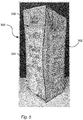
Fig. 1a is a perspective view of a package. -
Fig. 1b illustrates a piece of packaging material that can be folded into the package illustrated infig. 1a . -
Fig. 2 is a cross-sectional view of a piece of packaging material. -
Fig. 3a and 3b illustrate two different perspective views of package assembly. -
Fig. 4a illustrates a perspective view of a package assembly provided with a top protection arrangement. -
Fig. 4b illustrates a box filled with four package assemblies seen from above. -
Fig. 5 illustrates a perspective view of a package assembly provided with an hourglass-shaped rear section. -
Fig. 6 to 13 illustrate various examples of exoskeletons. -
Fig. 14 to 16 illustrate various examples of exoskeletons that can be used for producing multi-packs. -
Fig. 17 is a flowchart illustrating a method for producing a package assembly. -
Fig. 18 is a flowchart illustrating a method for producing a multi-pack. -
Fig. 1a generally illustrates an example of apackage 100, herein exemplified by a carton package, made from a piece of package material illustrated infig. 1b . Thepackage 100 comprises a number of panels divided from each other by weakening lines. The weakening lines provide for that the piece of packaging material can be reliably and efficiently folded into thepackage 100 by a packaging machine, also known as a filling machine. - In this example, the
package 100 comprises a firstrear panel 102, aleft panel 104, afront panel 106, aright panel 108 and a secondrear panel 110, which together form a sleeve-shaped main body of thepackage 100. As illustrated, the sleeve-shaped main body may have a rectangular cross-section. The first and secondrear panel rear panel 110, that is placed inside a peripheral part of the firstrear panel 102, can be protected by a plastic strip, sometimes referred to as a longitudinal sealing strip. - Further, the
package 100 comprises a first toprear panel 112, a left cornertop panel 114, a topfront panel 116, aright corner panel 118 and a second toprear panel 120, which together form a top section of thepackage 100. In a similar manner as the first and secondrear panel top panels package 100, the first and second reartop panels front panel 116, two sections of the left cornertop panel 114 are attached to each other, and two sections of the rightcorner top panel 118 are attached to each other. This is provided by a top transversal seal TTS made in the packaging machine after the package is filled with the product, or if filled upside down before the package is filled. - The
package 100 also comprises a first bottomrear panel 122, a left cornerbottom panel 124, a bottomfront panel 126, a rightcorner bottom panel 128 and a second bottomrear panel 130, which together form a bottom of the package. In a similar manner as the first and secondrear panel rear panels package 100 and thereby form the bottom, the first and second bottomrear panels front panel 126, two sections of the left cornerbottom panel 124 are attached to each other, and two sections of the rightcorner bottom panel 128 are attached to each other, such that a bottom transversal seal BTS is formed. - In case the
package 100 is produced in a roll-fed packaging machine, a number of pieces of packaging material is provided after one another on a reel of packaging material. By having the pieces of packaging material arranged in this way the top transversal seal TTS can be formed at the same time as the bottom transversal seal BTS is made in a subsequent package. After having made the transversal seals, the packages can be separated from each other by cutting them apart in a section between the transversal seals. - To form the top transversal seal TTS and the bottom transversal seal BTS, a first
top seal section 134 and a secondtop sealing section 132 as well as a firstbottom sealing section 136 and a secondtop sealing section 138 can be provided. After having made the top and bottom transversal seals, the packaging material can be separated such that the firsttop sealing section 132 and the secondtop sealing section 134 form an upper part of the top of thepackage 100, and in the firstbottom sealing section 136 and the secondbottom sealing section 138 form a lower part of the bottom of thepackage 100. To form the longitudinal sealing, alongitudinal sealing section 140 can be used. - In case the package is produced in a blanks-fed packaging machine, the longitudinal seal LS is provided beforehand, that is, the first
rear panel 102 is attached to the secondrear panel 110 via thelongitudinal section 140, such that a sleeve-shaped piece of packaging material is provided. In addition, the separation, also referred to as cutting, can be made when producing blanks to be fed into the blanks-fed packaging machine. - In the sleeve-shaped piece of packaging material used for blanks-fed packaging machines, the longitudinal seal LS may be placed in an intersection between a
rear section 140 and one of theside sections rear section 140 of thepackage 100 may comprise only one panel. - Further, in addition to having different panel arrangements, it is also possible to form a
top section 146 and abottom section 148 in different ways. For instance, as illustrated infig. 1a , thetop section 146 may be formed by folding down atop fin 150, comprising the top transversal seal TTS, towards afront section 152. Another possibility is to fold thetop fin 152 towards therear section 140, that is, towards the longitudinal seal LS. In a similar manner, abottom fin 154 can be folded down towards thefront section 152 or towards therear section 140. -
Fig. 2 generally illustrates by way of example apackaging material 200 that can be used for forming thepackage 100. - Facing the surrounding space, an
outer coating 202 may be provided. Theouter coating 202 may serve the purpose of avoiding that moisture of water is coming into contact with aprinting layer 204 placed inside theouter coating 202. Theprinting layer 204 can comprise ink or any other material used for providing a print on thepackage 100. - Inside the
printing layer 204, a first and asecond paperboard layer package 100. Thefirst paperboard layer 206 may be bleached paperboard with or without clay coat. Thesecond paperboard layer 208 may be bleached or unbleached paperboard. - Next a
lamination layer 210 made of plastic material can be provided. Thelamination layer 210 can provide for that microorganisms are hindered from coming into contact with the product held inside thepackage 100. - Inside the
lamination layer 210, anAluminum foil 212 can be provided. TheAluminum foil 212 can provide for that light, oxygen and odors are hindered from coming into contact with the product held inside thepackage 100, but also that flavors inside the package can be released from thepackage 100. TheAluminum foil 212 does however not exist in all types of packaging material. For instance, in the packaging material used for packages for chilled products, i.e. products that will be refrigerated, theAluminum foil 212 is most often left out and replaced by a combination of lamination layers and paperboard layers. - Closest to the product held inside the
package 100, a first and a secondinternal coating 214, 216, made of e.g. plastics material, can be provided. One purpose with these are that the product is hindered from coming in direct contact with theAluminum foil 212. -
Fig. 3a and 3b illustrate by way of example apackage assembly 300 comprising apackage 302, similar to thepackage 100 illustrated infig. 1a and 1b , but with a slantedtop section 304 and provided with acap 306. In addition, to improve robustness and to protect thepackage 302, anexoskeleton 308 in the form of a cardboard element, that is a piece comprising at least one layer of cardboard, is attached to the package. In this particular example, theexoskeleton 308 is attached to the rear section of the package, to a part of the top section and to the bottom section. By having theexoskeleton 308 attached to the rear section, the longitudinal seal can be protected. By having theexoskeleton 308 attached to the bottom section, the bottom transversal seal can be protected, e.g. in that flaps formed by the left and right corner bottom panels can be securely kept in place. Similarly, by having theexoskeleton 308 attached to part of the top section the top transversal seal TTS can be protected. - As illustrated in
fig. 3a and 3b the top transversal seal TTS can be folded down towards the rear section. Since the longitudinal seal LS forms part of the top transversal seal TTS and is placed on the rear section, folding the top transversal seal TTS towards the rear section implies that the longitudinal seal LS is folded, that is, four layers of packaging material is folded. This results in that there is increased risk that the top fin is raised, that is, the top fin does not lay down close to the top section. By having theexoskeleton 308 placed such that this covers at least part of the top transversal seal TTS, the risk that the top fin is raised can be mitigated. -
Fig. 4a illustrates another example of apackage assembly 400. Theexoskeleton 402 used in this exemplified package assembly comprises, in line with theexoskeleton 308 illustrated infig. 3 , arear section element 404 attached to the rear section of thepackage 302, that is, the same type of package as illustrated infig. 3 , and abottom section element 406 attached to the bottom section of the package. However, unlike theexoskeleton 308 illustrated infig. 3 , theexoskeleton 402 illustrated infig. 4 , is provided with atop protection arrangement 408. Thetop protection arrangement 408 can be embodied in various ways. As illustrated, afirst element 410 may be arranged to face the top section of thepackage 302, and asecond element 412 may be used for forming a flat surface, also referred to as a stacking surface, such that stacking properties can be improved. To form the flat surface, when thepackage 302 is provided with the slantedtop section 304, as illustrated infig. 3 , athird element 414 may be used. Thethird element 414 may be connected to the first andsecond element second element 412 is attached to therear section element 404, but it is also possible to have thefirst element 410 attached to therear section element 404. - Due to the
third element 414, the first andsecond element space 416 between the first andsecond element fig. 4a , thecap 306 can be held in thespace 416. To fit thecap 306 in thespace 414, a first opening 418 may be provided in the first element and a second opening 420 may be provided in thesecond element 412. Further, even though not illustrated, if e.g. having a low profile cap, only the second opening 420, that is, the opening in the element closest to the top section, may be required to fit the cap in the space. Still an option, if having e.g. another type of opening device than thecap 306, such as a pull tab or a straw hole, the first and the second opening 418, 420 may be left out. -
Fig. 4b illustrates by way of example fourpackage assemblies 400, illustrated infig. 4a , placed in a cardboard box. By having thepackage assemblies 400 provided with thetop protection arrangements 408, a risk that the top sections are damaged during transport can be reduced. This may by way of example be relevant in e-commerce when thepackages 302 are distributed by ordinary mail package services. -
Fig. 5 illustrates another example of apackage assembly 500. Thepackage 302, similar to the packages illustrated infig. 3 and4 , has anexoskeleton 502 attached thereto that has arear section element 504 that is different from the rear section of the package. For instance, as illustrated, the rear section of thepackage 302 may be rectangular-shaped, while therear section element 504 is hourglass-shaped. Apart from providing a visual appeal, an advantage is that a user may be directed on how to grip thepackage assembly 500 when using it. Further, by having therear section element 504 provided with a width being smaller than the width of the rear section, thepackage assembly 500 can be easier for the user to grip, in particular if thepackaging material 200 thepackage 302 provides more flexibility than theexoskeleton 502. -
Fig. 6 to 13 illustrate eight different examples of exoskeletons that can be attached to packages. -
Fig. 6 illustrates a first example of anexoskeleton 600 in isolation. Theexoskeleton 600 comprises a first and a secondintermediate section element - The
exoskeleton 600 is further provided with atop protection arrangement 604 that comprises afirst element 606 arranged to face the top section of the package, asecond element 608 placed at a distance from thefirst element 606, athird element 610 connecting the first andsecond element fourth element 612 connected to thesecond element 608. As thetop protection arrangement 408 illustrated infig. 4a , thetop protection arrangement 604 is arranged to protect the top section of the package as well as the cap during transportation. In the protective state PS, the first element may be attached to the top section of the package, and the elements may be divided by folding lines such that thetop protection arrangement 604 can be moved easily between the protective state PS and a non-protective state NPS, that is, when at least part of thetop protection arrangement 604 has been removed or displaced by the user. -
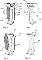
Fig. 7 illustrates another example of anexoskeleton 700. Theexoskeleton 700 is provided with an hourglass-shaped rear section element that can be attached to the same type of package as theexoskeleton 600 illustrated infig. 6 , but unlike theexoskeleton 600 illustrated infig. 6 , theexoskeleton 700 is not provided with intermediate side section elements. Theexoskeleton 700 may also be attached to a brick-shaped package, such as Tetra Brik™ marketed by Tetra Pak™, such that a package assembly similar to thepackage assembly 500 illustrated infig. 5 can be achieved. - The
exoskeleton 700 can be provided with atop protection arrangement 702. This may comprise afirst element 704 arranged to face the top section of the package, asecond element 706 arranged to form the flat surface, spaced apart from thefirst element 704, athird element 708 connecting the first andsecond element fourth element 710 connecting thesecond element 706 to the rear section. Folding lines may be provided between the different elements such that thetop protection arrangement 702 can be removed by the user before opening the package. - In
fig. 8 yet another example of anexoskeleton 800 is illustrated. As theexoskeleton 600 illustrated infig. 6 , theexoskeleton 800 is provided with a first and secondintermediate section elements 802a,b. Since the first and second intermediate section elements 802,802b is inclined with respect to the rear section element of theexoskeleton 800, having the intermediate section elements may provide increased robustness to the package assembly. Further, even though two intermediate section elements are illustrated, another option is to have theexoskeleton 800 provided with only one intermediate section element. The same holds true for theexoskeleton 600 illustrated infig. 6 . Unlike theexoskeleton 600 illustrated infig. 6 , theexoskeleton 800 is only provided with afirst element 804. - In
fig. 9 still another example of anexoskeleton 900 is illustrated. As theexoskeleton 700 illustrated infig. 7 , theexoskeleton 900 can, for the same reasons as mentioned above with respect tofig. 7 , be provided with a rear section element that is non-rectangular. As theexoskeleton 800 illustrated infig. 8 , afirst element 902 may be provided for protection of the top section of the package. - Still an example of an
exoskeleton 1000 is illustrated infig. 10 . Theexoskeleton 1000 can be provided with arear section element 1002 with one side being straight and the other side being curved. In line with the first and second intermediate section elements 602,602b illustrated infig. 6 , the curved side may be provided to fit with the package to which the exoskeleton is to be attached, or it may, e.g. if theexoskeleton 1000 is to attached to thepackage 302 with rectangular-shaped rear section, illustrated infig 3a and 3b , provide improved gripping properties. - A further example of an
exoskeleton 1100 is illustrated infig. 11 . In line with theexoskeleton 1000 illustrated infig. 10 , theexoskeleton 1100 can be provided with arear section element 1102 with one side being straight and the other side being curved. Further, a firstintermediate side section 1104 may be provided. In line with the first and second intermediate section elements 602,602b illustrated infig. 6 , the firstintermediate section element 1104 may be provided to fit with the package to which the exoskeleton is to be attached. - A further example of an
exoskeleton 1200 is illustrated infig. 12 . Theexoskeleton 1200 is provided with a rear section element that is rectangular-shaped, a top section element for protecting the top section of the package and a bottom section element for protecting the bottom section. - Still an example of an
exoskeleton 1300 is illustrated infig. 13 . Theexoskeleton 1300 is provided with anupper flap 1302 that is arranged to extend above the package to which it is attached. Theupper flap 1302 may comprise of a rear section element that is arranged to extend above the rear section of the package, aflap element 1304 and atop section element 1306 arranged to be attached to the top section of the package. Theupper flap 1302 may be provided with e.g. an opening such that the package assembly formed when the exoskeleton is attached to the package can be hanged on a hook. - In
fig. 14 , agroup 1400 comprising a number ofexoskeletons exoskeletons perforation lines - In
fig. 15 , agroup 1500 comprising a number ofexoskeletons perforation lines - The rear section elements of the
exoskeletons first attachment sections second attachment sections first attachment sections second attachment sections openings second attachment sections - In
fig. 16 , yet anothergroup 1600 of exoskeletons is illustrated by way of example. The exoskeletons of thegroup 1600 are similar to the exoskeletons of thegroup 1500 illustrated infig. 15 , but in addition to thegroup 1500 illustrated infig. 15 , thegroup 1600 is connected such that a 2x3 multi-pack can be achieved. Put differently, thegroup 1600 is designed such that packages can be placed side-to-side as well as front-to-front. -
Fig. 17 is a flow chart illustrating a method for producing the package assembly. In afirst step 1702, the package is provided, and in asecond step 1704 the exoskeleton is attached to the rear section of the package such that an improved robustness is achieved and that the longitudinal seal is protected. -
Fig. 18 is a flow chart illustrating a method for producing the multi-pack In afirst step 1802, the packages are provided, and in asecond step 1704 the exoskeletons are attached to the rear sections of the packages such that an improved robustness is achieved, that the longitudinal seals are protected, and that the packages are attached to each other. - From the description above follows that, although various embodiments of the invention have been described and shown, the invention is not restricted thereto, but may also be embodied in other ways within the scope of the subject-matter defined in the following claims.
Claims (15)
- A package assembly (300, 400, 500) comprising
a package (100,302) arranged to hold a food product, wherein the package (100,302) comprises a rear section (140) provided with a longitudinal seal (LS),
an exoskeleton (308, 402, 502, 600, 700, 800, 900, 1000,1100, 1200, 1300) attached to the rear section (140) of the package (100,302) such that an improved robustness is achieved and that the longitudinal seal (LS) is protected. - The package assembly (300, 400, 500) according to claim 1, wherein the package (100,302) further comprises a top section provided with a top transversal seal (TTS), and the exoskeleton is arranged to face the top section (146) such that the top transversal seal (TTS) is protected.
- The package assembly (300, 400) according to claim 2, wherein the top transversal seal (TTS) is provided in a top fin (150), and the top fin (150) is folded towards the longitudinal seal (LS), wherein the exoskeleton (308, 402, 600, 700) is arranged to face the top fin (150) that forms part of the top section (146) such that the top fin (150) is held in place.
- The package assembly (300,400, 500) according to any one of the preceding claims, wherein the package (302) further comprises a bottom section (148) provided with a bottom transversal seal (BTS), and the exoskeleton (308, 402, 502, 600, 700, 800, 900, 1000,1100, 1200, 1300) is attached to the bottom section () such that the bottom transversal seal (BTS) is protected.
- The package assembly (300, 400, 500) according to any one of the preceding claims, wherein the top section (146) is provided with an opening device (306), and the exoskeleton (402, 600, 700) comprises
a rear section element (404) attached to the rear section of the package, and
a top protection arrangement (408, 604, 702) arranged to be in a protective state (PS) and a non-protective state (NPS), said top protection arrangement comprises
a first element (410, 606, 704) that in the protective state (PS) is arranged to face the top section (146) of the package,
a second element (412, 608, 706) that in the protective state (PS) is arranged to form a stacking surface of the package assembly, and
a third element (414, 610, 708) connected to the first and second element, and that in the protective state (PS) is arranged to provide a distance (D) between the first and second element such that a space (416) is formed. - The packaging assembly (400) according to claim 5, wherein the opening device (306) is a cap (306), and the first element (410) is provided with a first opening (418) for holding the cap (306) in the protective state (PS), and the space (416) is arranged for holding the cap (306) in the protective state (PS) between the first and second element (410, 412).
- The packaging assembly (400) according to claim 6, wherein the second element (412) is provided with a second opening (420) for holding the cap (306) in the protective state (PS).
- The package assembly (300) according to any one of the preceding claims, wherein the top section is a slanted top section (304).
- The package assembly according to any one of the preceding claims, wherein the package comprises a side section placed next to the rear section, and an intermediate section placed between the rear section and the side section, wherein the exoskeleton (600, 800) is attached to the intermediate section.
- The package assembly (300, 400, 500) according to any one of the preceding claims, wherein the exoskeleton (308, 402, 502) comprises a cardboard layer.
- A multi-pack comprising
a number of package assemblies according to any one of the preceding claims,
wherein a number of exoskeletons (1402a, 1402b, 1402c,1402d, 1502a, 1502b, 1502c) of the number of package assemblies are attached to each other. - The multipack according to claim 11, wherein rear section elements of the number of package assemblies are attached to each other in a first attachment section (1506a, 1506b) and a second attachment section (1508a, 1508b), wherein the first and second attachment sections are spaced apart from each other.
- The multipack according to claim 10 or 11, wherein bottom section elements of the exoskeletons (1402a, 1402b, 1402c,1402d, 1502a, 1502b, 1502c) are attached to each other.
- A method (1700) for producing a package assembly (300, 400, 500) comprising a package (100, 302) arranged to hold a food product, wherein the package comprises a rear section (140) provided with a longitudinal seal (LS), and an exoskeleton (308, 402, 502, 600, 700, 800, 900, 1000,1100, 1200, 1300), said method comprising
providing (1702) the package, and
attaching (1704) the exoskeleton to the rear section (140) of the package such that an improved robustness is achieved and that the longitudinal seal (LS) is protected. - A method (1800) for producing a multi-pack comprising a number of package assemblies (300, 400, 500), each comprising a package (100, 302) arranged to hold a food product, wherein each package comprises a rear section (140) provided with a longitudinal seal (LS), wherein a number of exoskeletons (308, 402, 502, 600, 700, 800, 900, 1000,1100, 1200, 1300) of the number of package assemblies are attached to each other, said method comprising
providing (1802) the packages, and
attaching (1804) the number of exoskeletons to the rear sections (140) of the packages such that an improved robustness is achieved, that the longitudinal seals (LS) are protected, and that the number of packages are attached to each other.
Applications Claiming Priority (1)
| Application Number | Priority Date | Filing Date | Title |
|---|---|---|---|
| EP19155906 | 2019-02-07 |
Publications (2)
| Publication Number | Publication Date |
|---|---|
| EP3693285A1 true EP3693285A1 (en) | 2020-08-12 |
| EP3693285B1 EP3693285B1 (en) | 2022-11-09 |
Family
ID=65363116
Family Applications (1)
| Application Number | Title | Priority Date | Filing Date |
|---|---|---|---|
| EP20154348.5A Active EP3693285B1 (en) | 2019-02-07 | 2020-01-29 | Package assembly and multi-pack |
Country Status (4)
| Country | Link |
|---|---|
| US (1) | US12297021B2 (en) |
| EP (1) | EP3693285B1 (en) |
| MX (1) | MX2021009332A (en) |
| WO (1) | WO2020160977A1 (en) |
Families Citing this family (2)
| Publication number | Priority date | Publication date | Assignee | Title |
|---|---|---|---|---|
| USD1069578S1 (en) * | 2022-08-08 | 2025-04-08 | Tetra Laval Holdings & Finance S.A. | Lid for containers |
| USD1124859S1 (en) * | 2023-12-30 | 2026-05-05 | Parksons Packaging Ltd. | Fluid dispenser |
Citations (3)
| Publication number | Priority date | Publication date | Assignee | Title |
|---|---|---|---|---|
| EP2650223A1 (en) * | 2010-12-06 | 2013-10-16 | Tetra Laval Holdings & Finance SA | Production method for packaging container, and packaging container |
| WO2014014738A1 (en) * | 2012-07-17 | 2014-01-23 | Meadwestvaco Packaging Systems, Llc | Carton and blank therefor |
| WO2016173907A1 (en) | 2015-04-30 | 2016-11-03 | Tetra Laval Holdings & Finance S.A. | Method for producing a package assembly, a package assembly and a blank to be shaped into a secondary package |
Family Cites Families (4)
| Publication number | Priority date | Publication date | Assignee | Title |
|---|---|---|---|---|
| NZ238520A (en) * | 1991-06-13 | 1996-06-25 | Printpac Ueb Ltd Substituted F | Beverage can package: rims of cans engaged by slotted sheet with central channel, sheet reinforced by separate bridge part |
| US5419431A (en) * | 1992-07-28 | 1995-05-30 | Gerhardt Schubert Gmbh | Separable container for storage of plural articles |
| KR20030036628A (en) * | 2000-07-31 | 2003-05-09 | 테트라 라발 홀딩스 앤드 피낭스 소시에떼아노님 | Method of manufacturing paper packaging container and pater packaging container |
| JP4442796B2 (en) * | 2003-01-24 | 2010-03-31 | 日本テトラパック株式会社 | Packaging container and spigot attached to packaging container |
-
2020
- 2020-01-29 WO PCT/EP2020/052161 patent/WO2020160977A1/en not_active Ceased
- 2020-01-29 MX MX2021009332A patent/MX2021009332A/en unknown
- 2020-01-29 EP EP20154348.5A patent/EP3693285B1/en active Active
- 2020-01-29 US US17/310,407 patent/US12297021B2/en active Active
Patent Citations (3)
| Publication number | Priority date | Publication date | Assignee | Title |
|---|---|---|---|---|
| EP2650223A1 (en) * | 2010-12-06 | 2013-10-16 | Tetra Laval Holdings & Finance SA | Production method for packaging container, and packaging container |
| WO2014014738A1 (en) * | 2012-07-17 | 2014-01-23 | Meadwestvaco Packaging Systems, Llc | Carton and blank therefor |
| WO2016173907A1 (en) | 2015-04-30 | 2016-11-03 | Tetra Laval Holdings & Finance S.A. | Method for producing a package assembly, a package assembly and a blank to be shaped into a secondary package |
Also Published As
| Publication number | Publication date |
|---|---|
| US20220089343A1 (en) | 2022-03-24 |
| WO2020160977A1 (en) | 2020-08-13 |
| BR112021013627A2 (en) | 2021-09-14 |
| EP3693285B1 (en) | 2022-11-09 |
| US12297021B2 (en) | 2025-05-13 |
| MX2021009332A (en) | 2021-09-08 |
Similar Documents
| Publication | Publication Date | Title |
|---|---|---|
| US10202228B2 (en) | Carton with asymmetrical corners | |
| US7448492B2 (en) | Carrier package and blank | |
| ES2699727T3 (en) | Sealed container for pourable food products and packaging material to produce sealed packages for pourable food products | |
| EP3140217B1 (en) | Carrier for containers | |
| ES2592630T3 (en) | Transport device with retention feature | |
| US11299314B2 (en) | Package sleeve, package and method for manufacturing a package | |
| US9783334B2 (en) | Shipping and display container | |
| US8376213B2 (en) | Carrier with locking features | |
| US9840358B2 (en) | Carton with article protection feature | |
| US9487319B2 (en) | Method of manufacturing packaging container and packaging container | |
| EP3693285B1 (en) | Package assembly and multi-pack | |
| US20190337664A1 (en) | Package Sleeve, Package and Method for Manufacturing a Package | |
| US12258185B2 (en) | Paper-based or paperboard-based container and related methods | |
| US20190337666A1 (en) | Sleeve Blank, Package Sleeve, Package and Method for Manufacturing a Sleeve Blank, a Package Sleeve and a Package | |
| CN105452124A (en) | Carton with insert | |
| US20160340099A1 (en) | Packaging container with opening device and method for manufacturing the same | |
| US8272559B2 (en) | Packs and methods of erecting packs | |
| US20250178773A1 (en) | Paper-based or paperboard-based container and related methods | |
| FI128014B (en) | Box for Bag-in-Box package | |
| US12617595B2 (en) | Sleeve for holding containers | |
| BR112021013627B1 (en) | PACKAGING ASSEMBLY, MULTI-PACK TYPE PACKAGING, AND METHODS FOR PRODUCING A PACKAGING ASSEMBLY AND A MULTI-PACK TYPE PACKAGING | |
| US20130098977A1 (en) | Carrier with Retention Features | |
| US20260035131A1 (en) | Packaging construct with liner | |
| CN121079254A (en) | Packaging blank for forming a package and package formed from a packaging blank | |
| WO2021234024A1 (en) | Paper-based or paperboard-based container |
Legal Events
| Date | Code | Title | Description |
|---|---|---|---|
| PUAI | Public reference made under article 153(3) epc to a published international application that has entered the european phase |
Free format text: ORIGINAL CODE: 0009012 |
|
| STAA | Information on the status of an ep patent application or granted ep patent |
Free format text: STATUS: THE APPLICATION HAS BEEN PUBLISHED |
|
| AK | Designated contracting states |
Kind code of ref document: A1 Designated state(s): AL AT BE BG CH CY CZ DE DK EE ES FI FR GB GR HR HU IE IS IT LI LT LU LV MC MK MT NL NO PL PT RO RS SE SI SK SM TR |
|
| AX | Request for extension of the european patent |
Extension state: BA ME |
|
| STAA | Information on the status of an ep patent application or granted ep patent |
Free format text: STATUS: REQUEST FOR EXAMINATION WAS MADE |
|
| 17P | Request for examination filed |
Effective date: 20210212 |
|
| RBV | Designated contracting states (corrected) |
Designated state(s): AL AT BE BG CH CY CZ DE DK EE ES FI FR GB GR HR HU IE IS IT LI LT LU LV MC MK MT NL NO PL PT RO RS SE SI SK SM TR |
|
| STAA | Information on the status of an ep patent application or granted ep patent |
Free format text: STATUS: EXAMINATION IS IN PROGRESS |
|
| 17Q | First examination report despatched |
Effective date: 20210713 |
|
| REG | Reference to a national code |
Ref country code: DE Ref legal event code: R079 Ref document number: 602020006104 Country of ref document: DE Free format text: PREVIOUS MAIN CLASS: B65D0005740000 Ipc: B65D0005440000 |
|
| GRAP | Despatch of communication of intention to grant a patent |
Free format text: ORIGINAL CODE: EPIDOSNIGR1 |
|
| STAA | Information on the status of an ep patent application or granted ep patent |
Free format text: STATUS: GRANT OF PATENT IS INTENDED |
|
| RIC1 | Information provided on ipc code assigned before grant |
Ipc: B65D 5/06 20060101ALI20220503BHEP Ipc: B65D 77/28 20060101ALI20220503BHEP Ipc: B65D 71/00 20060101ALI20220503BHEP Ipc: B65D 5/74 20060101ALI20220503BHEP Ipc: B65D 5/44 20060101AFI20220503BHEP |
|
| INTG | Intention to grant announced |
Effective date: 20220603 |
|
| GRAS | Grant fee paid |
Free format text: ORIGINAL CODE: EPIDOSNIGR3 |
|
| GRAA | (expected) grant |
Free format text: ORIGINAL CODE: 0009210 |
|
| STAA | Information on the status of an ep patent application or granted ep patent |
Free format text: STATUS: THE PATENT HAS BEEN GRANTED |
|
| AK | Designated contracting states |
Kind code of ref document: B1 Designated state(s): AL AT BE BG CH CY CZ DE DK EE ES FI FR GB GR HR HU IE IS IT LI LT LU LV MC MK MT NL NO PL PT RO RS SE SI SK SM TR |
|
| REG | Reference to a national code |
Ref country code: GB Ref legal event code: FG4D |
|
| REG | Reference to a national code |
Ref country code: CH Ref legal event code: EP Ref country code: AT Ref legal event code: REF Ref document number: 1530210 Country of ref document: AT Kind code of ref document: T Effective date: 20221115 |
|
| REG | Reference to a national code |
Ref country code: DE Ref legal event code: R096 Ref document number: 602020006104 Country of ref document: DE |
|
| REG | Reference to a national code |
Ref country code: IE Ref legal event code: FG4D |
|
| REG | Reference to a national code |
Ref country code: LT Ref legal event code: MG9D |
|
| REG | Reference to a national code |
Ref country code: NL Ref legal event code: MP Effective date: 20221109 |
|
| REG | Reference to a national code |
Ref country code: AT Ref legal event code: MK05 Ref document number: 1530210 Country of ref document: AT Kind code of ref document: T Effective date: 20221109 |
|
| PG25 | Lapsed in a contracting state [announced via postgrant information from national office to epo] |
Ref country code: SE Free format text: LAPSE BECAUSE OF FAILURE TO SUBMIT A TRANSLATION OF THE DESCRIPTION OR TO PAY THE FEE WITHIN THE PRESCRIBED TIME-LIMIT Effective date: 20221109 Ref country code: PT Free format text: LAPSE BECAUSE OF FAILURE TO SUBMIT A TRANSLATION OF THE DESCRIPTION OR TO PAY THE FEE WITHIN THE PRESCRIBED TIME-LIMIT Effective date: 20230309 Ref country code: NO Free format text: LAPSE BECAUSE OF FAILURE TO SUBMIT A TRANSLATION OF THE DESCRIPTION OR TO PAY THE FEE WITHIN THE PRESCRIBED TIME-LIMIT Effective date: 20230209 Ref country code: LT Free format text: LAPSE BECAUSE OF FAILURE TO SUBMIT A TRANSLATION OF THE DESCRIPTION OR TO PAY THE FEE WITHIN THE PRESCRIBED TIME-LIMIT Effective date: 20221109 Ref country code: FI Free format text: LAPSE BECAUSE OF FAILURE TO SUBMIT A TRANSLATION OF THE DESCRIPTION OR TO PAY THE FEE WITHIN THE PRESCRIBED TIME-LIMIT Effective date: 20221109 Ref country code: ES Free format text: LAPSE BECAUSE OF FAILURE TO SUBMIT A TRANSLATION OF THE DESCRIPTION OR TO PAY THE FEE WITHIN THE PRESCRIBED TIME-LIMIT Effective date: 20221109 Ref country code: AT Free format text: LAPSE BECAUSE OF FAILURE TO SUBMIT A TRANSLATION OF THE DESCRIPTION OR TO PAY THE FEE WITHIN THE PRESCRIBED TIME-LIMIT Effective date: 20221109 |
|
| PG25 | Lapsed in a contracting state [announced via postgrant information from national office to epo] |
Ref country code: RS Free format text: LAPSE BECAUSE OF FAILURE TO SUBMIT A TRANSLATION OF THE DESCRIPTION OR TO PAY THE FEE WITHIN THE PRESCRIBED TIME-LIMIT Effective date: 20221109 Ref country code: PL Free format text: LAPSE BECAUSE OF FAILURE TO SUBMIT A TRANSLATION OF THE DESCRIPTION OR TO PAY THE FEE WITHIN THE PRESCRIBED TIME-LIMIT Effective date: 20221109 Ref country code: LV Free format text: LAPSE BECAUSE OF FAILURE TO SUBMIT A TRANSLATION OF THE DESCRIPTION OR TO PAY THE FEE WITHIN THE PRESCRIBED TIME-LIMIT Effective date: 20221109 Ref country code: IS Free format text: LAPSE BECAUSE OF FAILURE TO SUBMIT A TRANSLATION OF THE DESCRIPTION OR TO PAY THE FEE WITHIN THE PRESCRIBED TIME-LIMIT Effective date: 20230309 Ref country code: HR Free format text: LAPSE BECAUSE OF FAILURE TO SUBMIT A TRANSLATION OF THE DESCRIPTION OR TO PAY THE FEE WITHIN THE PRESCRIBED TIME-LIMIT Effective date: 20221109 Ref country code: GR Free format text: LAPSE BECAUSE OF FAILURE TO SUBMIT A TRANSLATION OF THE DESCRIPTION OR TO PAY THE FEE WITHIN THE PRESCRIBED TIME-LIMIT Effective date: 20230210 |
|
| P01 | Opt-out of the competence of the unified patent court (upc) registered |
Effective date: 20230426 |
|
| PG25 | Lapsed in a contracting state [announced via postgrant information from national office to epo] |
Ref country code: NL Free format text: LAPSE BECAUSE OF FAILURE TO SUBMIT A TRANSLATION OF THE DESCRIPTION OR TO PAY THE FEE WITHIN THE PRESCRIBED TIME-LIMIT Effective date: 20221109 |
|
| PG25 | Lapsed in a contracting state [announced via postgrant information from national office to epo] |
Ref country code: SM Free format text: LAPSE BECAUSE OF FAILURE TO SUBMIT A TRANSLATION OF THE DESCRIPTION OR TO PAY THE FEE WITHIN THE PRESCRIBED TIME-LIMIT Effective date: 20221109 Ref country code: RO Free format text: LAPSE BECAUSE OF FAILURE TO SUBMIT A TRANSLATION OF THE DESCRIPTION OR TO PAY THE FEE WITHIN THE PRESCRIBED TIME-LIMIT Effective date: 20221109 Ref country code: EE Free format text: LAPSE BECAUSE OF FAILURE TO SUBMIT A TRANSLATION OF THE DESCRIPTION OR TO PAY THE FEE WITHIN THE PRESCRIBED TIME-LIMIT Effective date: 20221109 Ref country code: DK Free format text: LAPSE BECAUSE OF FAILURE TO SUBMIT A TRANSLATION OF THE DESCRIPTION OR TO PAY THE FEE WITHIN THE PRESCRIBED TIME-LIMIT Effective date: 20221109 Ref country code: CZ Free format text: LAPSE BECAUSE OF FAILURE TO SUBMIT A TRANSLATION OF THE DESCRIPTION OR TO PAY THE FEE WITHIN THE PRESCRIBED TIME-LIMIT Effective date: 20221109 |
|
| REG | Reference to a national code |
Ref country code: DE Ref legal event code: R097 Ref document number: 602020006104 Country of ref document: DE |
|
| PG25 | Lapsed in a contracting state [announced via postgrant information from national office to epo] |
Ref country code: SK Free format text: LAPSE BECAUSE OF FAILURE TO SUBMIT A TRANSLATION OF THE DESCRIPTION OR TO PAY THE FEE WITHIN THE PRESCRIBED TIME-LIMIT Effective date: 20221109 Ref country code: AL Free format text: LAPSE BECAUSE OF FAILURE TO SUBMIT A TRANSLATION OF THE DESCRIPTION OR TO PAY THE FEE WITHIN THE PRESCRIBED TIME-LIMIT Effective date: 20221109 |
|
| REG | Reference to a national code |
Ref country code: CH Ref legal event code: PL |
|
| PLBE | No opposition filed within time limit |
Free format text: ORIGINAL CODE: 0009261 |
|
| STAA | Information on the status of an ep patent application or granted ep patent |
Free format text: STATUS: NO OPPOSITION FILED WITHIN TIME LIMIT |
|
| PG25 | Lapsed in a contracting state [announced via postgrant information from national office to epo] |
Ref country code: LU Free format text: LAPSE BECAUSE OF NON-PAYMENT OF DUE FEES Effective date: 20230129 |
|
| REG | Reference to a national code |
Ref country code: BE Ref legal event code: MM Effective date: 20230131 |
|
| 26N | No opposition filed |
Effective date: 20230810 |
|
| PG25 | Lapsed in a contracting state [announced via postgrant information from national office to epo] |
Ref country code: LI Free format text: LAPSE BECAUSE OF NON-PAYMENT OF DUE FEES Effective date: 20230131 Ref country code: CH Free format text: LAPSE BECAUSE OF NON-PAYMENT OF DUE FEES Effective date: 20230131 |
|
| PG25 | Lapsed in a contracting state [announced via postgrant information from national office to epo] |
Ref country code: SI Free format text: LAPSE BECAUSE OF FAILURE TO SUBMIT A TRANSLATION OF THE DESCRIPTION OR TO PAY THE FEE WITHIN THE PRESCRIBED TIME-LIMIT Effective date: 20221109 Ref country code: FR Free format text: LAPSE BECAUSE OF NON-PAYMENT OF DUE FEES Effective date: 20230131 Ref country code: BE Free format text: LAPSE BECAUSE OF NON-PAYMENT OF DUE FEES Effective date: 20230131 |
|
| PG25 | Lapsed in a contracting state [announced via postgrant information from national office to epo] |
Ref country code: IE Free format text: LAPSE BECAUSE OF NON-PAYMENT OF DUE FEES Effective date: 20230129 |
|
| PG25 | Lapsed in a contracting state [announced via postgrant information from national office to epo] |
Ref country code: MC Free format text: LAPSE BECAUSE OF FAILURE TO SUBMIT A TRANSLATION OF THE DESCRIPTION OR TO PAY THE FEE WITHIN THE PRESCRIBED TIME-LIMIT Effective date: 20221109 |
|
| PG25 | Lapsed in a contracting state [announced via postgrant information from national office to epo] |
Ref country code: MC Free format text: LAPSE BECAUSE OF FAILURE TO SUBMIT A TRANSLATION OF THE DESCRIPTION OR TO PAY THE FEE WITHIN THE PRESCRIBED TIME-LIMIT Effective date: 20221109 |
|
| GBPC | Gb: european patent ceased through non-payment of renewal fee |
Effective date: 20240129 |
|
| PG25 | Lapsed in a contracting state [announced via postgrant information from national office to epo] |
Ref country code: GB Free format text: LAPSE BECAUSE OF NON-PAYMENT OF DUE FEES Effective date: 20240129 |
|
| PG25 | Lapsed in a contracting state [announced via postgrant information from national office to epo] |
Ref country code: GB Free format text: LAPSE BECAUSE OF NON-PAYMENT OF DUE FEES Effective date: 20240129 |
|
| PG25 | Lapsed in a contracting state [announced via postgrant information from national office to epo] |
Ref country code: BG Free format text: LAPSE BECAUSE OF FAILURE TO SUBMIT A TRANSLATION OF THE DESCRIPTION OR TO PAY THE FEE WITHIN THE PRESCRIBED TIME-LIMIT Effective date: 20221109 |
|
| PG25 | Lapsed in a contracting state [announced via postgrant information from national office to epo] |
Ref country code: BG Free format text: LAPSE BECAUSE OF FAILURE TO SUBMIT A TRANSLATION OF THE DESCRIPTION OR TO PAY THE FEE WITHIN THE PRESCRIBED TIME-LIMIT Effective date: 20221109 |
|
| PGFP | Annual fee paid to national office [announced via postgrant information from national office to epo] |
Ref country code: DE Payment date: 20250129 Year of fee payment: 6 |
|
| PGFP | Annual fee paid to national office [announced via postgrant information from national office to epo] |
Ref country code: IT Payment date: 20250122 Year of fee payment: 6 |
|
| PGFP | Annual fee paid to national office [announced via postgrant information from national office to epo] |
Ref country code: TR Payment date: 20250117 Year of fee payment: 6 |
|
| PG25 | Lapsed in a contracting state [announced via postgrant information from national office to epo] |
Ref country code: CY Free format text: LAPSE BECAUSE OF FAILURE TO SUBMIT A TRANSLATION OF THE DESCRIPTION OR TO PAY THE FEE WITHIN THE PRESCRIBED TIME-LIMIT; INVALID AB INITIO Effective date: 20200129 |
|
| PG25 | Lapsed in a contracting state [announced via postgrant information from national office to epo] |
Ref country code: HU Free format text: LAPSE BECAUSE OF FAILURE TO SUBMIT A TRANSLATION OF THE DESCRIPTION OR TO PAY THE FEE WITHIN THE PRESCRIBED TIME-LIMIT; INVALID AB INITIO Effective date: 20200129 |