EP3693276B1 - Environmental control systems and methods of controlling airflow through environmental control systems - Google Patents
Environmental control systems and methods of controlling airflow through environmental control systems Download PDFInfo
- Publication number
- EP3693276B1 EP3693276B1 EP19210056.8A EP19210056A EP3693276B1 EP 3693276 B1 EP3693276 B1 EP 3693276B1 EP 19210056 A EP19210056 A EP 19210056A EP 3693276 B1 EP3693276 B1 EP 3693276B1
- Authority
- EP
- European Patent Office
- Prior art keywords
- flow
- air
- air flow
- control valve
- loop module
- Prior art date
- Legal status (The legal status is an assumption and is not a legal conclusion. Google has not performed a legal analysis and makes no representation as to the accuracy of the status listed.)
- Active
Links
Images


Classifications
-
- B—PERFORMING OPERATIONS; TRANSPORTING
- B64—AIRCRAFT; AVIATION; COSMONAUTICS
- B64D—EQUIPMENT FOR FITTING IN OR TO AIRCRAFT; FLIGHT SUITS; PARACHUTES; ARRANGEMENT OR MOUNTING OF POWER PLANTS OR PROPULSION TRANSMISSIONS IN AIRCRAFT
- B64D13/00—Arrangements or adaptations of air-treatment apparatus for aircraft crew or passengers, or freight space
- B64D13/06—Arrangements or adaptations of air-treatment apparatus for aircraft crew or passengers, or freight space the air being conditioned
-
- F—MECHANICAL ENGINEERING; LIGHTING; HEATING; WEAPONS; BLASTING
- F02—COMBUSTION ENGINES; HOT-GAS OR COMBUSTION-PRODUCT ENGINE PLANTS
- F02C—GAS-TURBINE PLANTS; AIR INTAKES FOR JET-PROPULSION PLANTS; CONTROLLING FUEL SUPPLY IN AIR-BREATHING JET-PROPULSION PLANTS
- F02C6/00—Plural gas-turbine plants; Combinations of gas-turbine plants with other apparatus; Adaptations of gas-turbine plants for special use
- F02C6/04—Gas-turbine plants providing heated or pressurised working fluid for other apparatus, e.g. without mechanical power output
- F02C6/06—Gas-turbine plants providing heated or pressurised working fluid for other apparatus, e.g. without mechanical power output providing compressed gas
- F02C6/08—Gas-turbine plants providing heated or pressurised working fluid for other apparatus, e.g. without mechanical power output providing compressed gas the gas being bled from the gas-turbine compressor
-
- G—PHYSICS
- G05—CONTROLLING; REGULATING
- G05B—CONTROL OR REGULATING SYSTEMS IN GENERAL; FUNCTIONAL ELEMENTS OF SUCH SYSTEMS; MONITORING OR TESTING ARRANGEMENTS FOR SUCH SYSTEMS OR ELEMENTS
- G05B11/00—Automatic controllers
- G05B11/01—Automatic controllers electric
- G05B11/36—Automatic controllers electric with provision for obtaining particular characteristics, e.g. proportional, integral, differential
- G05B11/42—Automatic controllers electric with provision for obtaining particular characteristics, e.g. proportional, integral, differential for obtaining a characteristic which is both proportional and time-dependent, e.g. P. I., P. I. D.
-
- G—PHYSICS
- G05—CONTROLLING; REGULATING
- G05B—CONTROL OR REGULATING SYSTEMS IN GENERAL; FUNCTIONAL ELEMENTS OF SUCH SYSTEMS; MONITORING OR TESTING ARRANGEMENTS FOR SUCH SYSTEMS OR ELEMENTS
- G05B13/00—Adaptive control systems, i.e. systems automatically adjusting themselves to have a performance which is optimum according to some preassigned criterion
-
- G—PHYSICS
- G05—CONTROLLING; REGULATING
- G05D—SYSTEMS FOR CONTROLLING OR REGULATING NON-ELECTRIC VARIABLES
- G05D7/00—Control of flow
- G05D7/06—Control of flow characterised by the use of electric means
- G05D7/0617—Control of flow characterised by the use of electric means specially adapted for fluid materials
- G05D7/0629—Control of flow characterised by the use of electric means specially adapted for fluid materials characterised by the type of regulator means
- G05D7/0635—Control of flow characterised by the use of electric means specially adapted for fluid materials characterised by the type of regulator means by action on throttling means
-
- B—PERFORMING OPERATIONS; TRANSPORTING
- B64—AIRCRAFT; AVIATION; COSMONAUTICS
- B64D—EQUIPMENT FOR FITTING IN OR TO AIRCRAFT; FLIGHT SUITS; PARACHUTES; ARRANGEMENT OR MOUNTING OF POWER PLANTS OR PROPULSION TRANSMISSIONS IN AIRCRAFT
- B64D13/00—Arrangements or adaptations of air-treatment apparatus for aircraft crew or passengers, or freight space
- B64D13/06—Arrangements or adaptations of air-treatment apparatus for aircraft crew or passengers, or freight space the air being conditioned
- B64D2013/0603—Environmental Control Systems
- B64D2013/0618—Environmental Control Systems with arrangements for reducing or managing bleed air, using another air source, e.g. ram air
-
- F—MECHANICAL ENGINEERING; LIGHTING; HEATING; WEAPONS; BLASTING
- F24—HEATING; RANGES; VENTILATING
- F24F—AIR-CONDITIONING; AIR-HUMIDIFICATION; VENTILATION; USE OF AIR CURRENTS FOR SCREENING
- F24F11/00—Control or safety arrangements
- F24F11/0001—Control or safety arrangements for ventilation
- F24F2011/0002—Control or safety arrangements for ventilation for admittance of outside air
-
- Y—GENERAL TAGGING OF NEW TECHNOLOGICAL DEVELOPMENTS; GENERAL TAGGING OF CROSS-SECTIONAL TECHNOLOGIES SPANNING OVER SEVERAL SECTIONS OF THE IPC; TECHNICAL SUBJECTS COVERED BY FORMER USPC CROSS-REFERENCE ART COLLECTIONS [XRACs] AND DIGESTS
- Y02—TECHNOLOGIES OR APPLICATIONS FOR MITIGATION OR ADAPTATION AGAINST CLIMATE CHANGE
- Y02T—CLIMATE CHANGE MITIGATION TECHNOLOGIES RELATED TO TRANSPORTATION
- Y02T50/00—Aeronautics or air transport
- Y02T50/50—On board measures aiming to increase energy efficiency
Definitions
- the present disclosure relates to environmental control systems, and more particularly to control of air flows through environmental control systems.
- Aircraft commonly employ aircraft cabin pressurization systems to supply air for the cabin air conditioning system.
- the aircraft cabin pressurization system generally uses bleed air from the engine compressor, which is routed through a heat exchanger and a compressor prior to provision to the aircraft cabin.
- the use of bleed air from the engine compressor allows the aircraft cabin to be maintained at desirable conditions irrespective of the flight condition of the aircraft.
- the amount of bleed air from the engine compressor is typically controlled to limit the efficiency loss to the engine associated with the bleed air extracted from the compressor.
- a method of controlling air flow in an environmental control system includes receiving a target total flow value and a combined flow measurement at an outer control loop module.
- a first air flow reference value is determined based on the target total flow value and the combined flow measurement using the outer control loop module.
- the first air flow reference value is communicated to an inner control loop module and a flow control valve command determined based at least in part on the first air flow reference value using the inner control loop module.
- the flow control valve command is communicated to a flow control valve operatively associated with the inner control loop module to control flow through the ECS using the flow control valve.
- further embodiments may include changing air flow through both the first air conduit and the second air conduit using the flow control valve.
- further embodiments may include wherein receiving the combined flow measurement comprises receiving a measurement of ECS output air flow to an aircraft cabin.
- further embodiments may include wherein receiving the combined flow measurement comprises receiving a first air flow measurement and a second air flow measurement, the method further comprising adding the first air flow measurement to the second air flow measurement.
- further embodiments may include (a) receiving a first air flow at the first air conduit, (b) receiving a second air flow at the second air conduit, (c) combining the first air flow and the second air flow within the ECS, and (d) communicating the combined first air flow and the second air flow system to an enclosure as an ECS output flow.
- further embodiments may include wherein the first air flow is a bleed air flow, wherein the second air flow is an ambient air flow.
- determining the first air flow reference value comprises employing a proportional-integral control algorithm.
- determining the flow control valve command comprises employing a proportional-integral control algorithm.
- the ECS includes a first air conduit and a second air conduit; a turbine in fluid communication with the first air conduit; a compressor in fluid communication with the second air conduit, wherein the compressor is operatively associated with the turbine; and a flow control valve arranged along the first air conduit.
- a controller having an inner control loop module cascaded with an outer control loop module is operatively connected to the flow control valve and is responsive to instructions recorded on a memory to a controller to (a) receive a target total flow value and a combined flow measurement at the outer control loop module, (b) determine a first air flow reference value based on the target total flow value and the combined flow measurement using the outer control loop module, (c) communicate the first air flow reference value to the inner control loop module, (d) determine a flow control valve command based at least in part on the first air flow reference value using the inner control loop module, and (e) communicate the flow control valve command to the flow control valve.
- further embodiments may include a compressor section of a gas turbine engine connected to the first air conduit by a bleed valve.
- further embodiments may include an ambient air intake connected to the second air conduit.
- further embodiments may include a union connecting the second air conduit to the first air conduit.
- further embodiments may include wherein the turbine has a turbine outlet, wherein the union is arranged downstream of the turbine outlet.
- further embodiments may include wherein the compressor has a compressor outlet, wherein the union is arranged downstream of the compressor outlet.
- further embodiments may include a combined flow sensor arranged between the union and an enclosure connected to the ECS.
- further embodiments may include a first air flow sensor in communication with the first air conduit, the first air sensor arranged to provide a first air flow measurement of a first air flow in the first air conduit, and a second air flow sensor in communication with the second air conduit, the second air flow sensor arranged to provide a second air flow measurement of a second air flow in the second air conduit, wherein the instructions further cause the controller to provide the combined flow measurement to the outer control module by adding the first air flow measurement to the second air flow measurement.
- further embodiments may include a first air flow sensor in communication with the first air conduit and arranged provide the first air flow measurement to the inner control module.
- further embodiments may include wherein the outer control loop module comprises a proportional-integral control algorithm, wherein the inner control loop module comprises a proportional-integral control algorithm.
- a computer program product tangibly embodied on a computer readable medium is additionally provided in claim 14.
- the computer program product including instructions that, when executed by a processor, cause the processor to execute operations including (a) receiving a target total flow value at an outer control loop module, (b) receiving a combined flow measurement at the outer control loop module, (c) determining a first air flow reference value based on the target total flow value and the combined flow measurement using the outer control loop module, (d) communicating the first air flow reference value to an inner control loop module, (e) determining a flow control valve command based at least in part on the first air flow reference value using the inner control loop module, and (f) communicating the flow control valve command to a flow control valve operatively associated with the inner control loop module.
- embodiments of the present disclosure can allow a single flow control valve to control flow of two air flows provided to an ECS, reducing complexity of the system and system control in comparison with systems controlling two flows independently.
- Technical of embodiments of the present disclosure can also provide relatively rapid bleed flow control and disturbance control in comparison to alternative control schemes. Directly controlling bleed flow can also simplify satisfying the maximum allowable bleed for requirement.
- FIG. 1 a partial view of an exemplary embodiment of an environmental control system (ECS) in accordance with the disclosure is shown in FIG. 1 and is designated generally by reference character 100.
- ECS environmental control system
- FIGS. 2-4 Other embodiments of methods of controlling airflow through environmental control systems, environmental control systems, and computer program products for controlling flow through environmental control systems in accordance with the disclosure, or aspects thereof, are provided in FIGS. 2-4 , as will be described.
- the systems and methods described herein can be used for environmental control systems supplied air from two or more sources, such as compressed bleed air from a gas turbine engine compressor section and uncompressed ambient air from the external environment, through the present disclosure is not limited to environmental air control systems employing ambient air flows or to aircraft environmental control systems in general.
- the aircraft 10 includes an enclosure 12 containing a cabin 14, a gas turbine engine 16, and the ECS 100.
- the enclosure 12 encloses the cabin 14 such that the environment within the cabin 14 can be maintained to within a predetermined pressure and temperature range.
- the ECS 100 provides an ECS output air flow 18 to the cabin 14.
- the cabin 14 can enclose, for example, a portion of an aircraft fuselage housing the aircraft flight deck, a crew space, and/or a passenger space of the aircraft 10.
- the gas turbine engine 16 includes a turbine section 20, a compressor section 22, and a bleed valve 24.
- the turbine section 20 is configured to extract work by expanding a working fluid flow provided thereto.
- the compressor section 22 is configured to ingest ambient air from the external environment 26, compress the ingested ambient air using work provided by the turbine section 20 to form a compressed gas flow, and communicate the compressed gas flow to a combustion section to generate the working fluid flow provided to the turbine section 20.
- the bleed valve 24 connects the ECS 100 to the compressor section 22 and is configured to provide a portion of the compressed gas flow to the ECS 100 as a first air flow 30, e.g., a bleed air flow, to the ECS 100.
- the ECS 100 receives both the first air flow 30 and a second air flow 34, e.g., an uncompressed ambient air flow, from an ambient air intake 32 carried by the aircraft 10, which is in fluid communication with the ambient external environment 26 outside the aircraft 10.
- the ECS 100 combines the second air flow 34 with the first air flow 30 and provides the combined flow an ECS output air flow 18 to the enclosure 12. While shown and described herein with the compressor section 22 of the gas turbine engine 16, it is to be understood and appreciated that other sources of pressurized gas can be employed and remain within the scope of the present disclosure, such as gas bottles, ground cart-mounted compressors, fan air, and/or ram air, as suitable for an intended application.
- the ECS 100 includes a first air conduit 102, a second air conduit 104, and a flow control valve 106.
- the ECS 100 also includes a turbine 108, a compressor 110, and a controller 112.
- the first air conduit 102 connects the bleed valve 24 to the enclosure 12 through the flow control valve 106 and turbine 108, the flow control valve 106 arranged between the bleed valve 24 and the turbine 108.
- the turbine 108 has a turbine inlet 114 and a turbine outlet 116, the turbine outlet 116 connected to the flow control valve 106 through the turbine inlet 114.
- the second air conduit 104 connects the ambient air intake 32 to the compressor 110, and therethrough to the enclosure 12 through the first air conduit 102.
- the compressor 110 has a compressor inlet 118 and a compressor outlet 120.
- the ambient air intake 32 is connected to the compressor inlet 118, and therethrough to the compressor outlet 120.
- a union 122 is located downstream of both the compressor outlet 120 and the turbine outlet 116, the union 122 connecting the second air conduit 104 to the first air conduit 102.
- the first air flow 30 and the second air flow 34 combine at the union 122 to form the ECS output air flow 18, which the ECS 100 provides to the enclosure 12.
- the turbine 108 is configured to extract work 121 from the first air flow 30 as the first air flow 30 traverses the turbine 108, and is the operatively connected to the compressor 110.
- Connection of the turbine 108 to the compressor 110 can be, for example, via one or more of a shaft 123, a gear 124, a chain 126, and/or a belt 128, as suitable for an intended application.
- operative connection of the turbine 108 to the compressor 110 enables the turbine 108 to power the compressor 110 using work 121 extracted from the first air flow 30 as the first air flow 30 traverses the turbine 108. This limits the efficiency loss associated with bleeding a portion of the compressed gas flow generated by the compressor section 22 (shown in FIG. 1 ) of the gas turbine engine 16 (shown in FIG. 1 ) as the first air flow 30.
- the compressor 110 is configured to compress the second air flow 34 as the second air flow 34 traverses the compressor 110. More specifically, the compressor 110 compresses the second air flow 34 as the second air flow 34 traverses the compressor 110 according to the amount of work 121 communicated to the compressor 110 by the turbine 108. The amount of work 121 communicated to the compressor 110 by the turbine 108 in turn depends upon the mass flow rate of first air flow 30 provided to the turbine 108 by the first air conduit 102. The actual mass flow rate of first air flow 30 provided to the ECS 100 during operation is in turn controlled by the flow control valve 106.
- the flow control valve 106 is configured and adapted for modulating, i.e., increasing or decreasing, the mass flow rate of the first air flow 30 according to a flow control valve command signal 130 received from the controller 112.
- a flow control valve command signal 130 received from the controller 112.
- changing mass flow rate of the first air flow 30 changes the mass flow rate of the second air flow 34 according to the change in work 121 extracted by the turbine 108 from the first air flow 30.
- the flow control valve 106 is operatively associated with the controller 112, for example, through a communication link 132 connecting the controller 112 to the flow control valve 106. It is contemplated that the communication link 132 can be wired, wireless, analog, and/or digital, as suitable for an intended application.
- the controller 112 includes a processor 134, a device interface 136, and a memory 138.
- the memory 138 includes a non-transitory machine-readable medium having a plurality of program modules 140 recorded on the memory 138.
- the plurality of program modules 140 have instructions that, when read by the processor 134, cause the controller 112 to execute certain operations. Among those operations include the operations of a method 200 (shown in FIG. 4 ) of controlling air flow through the ECS 100.
- the plurality of program modules 140 include an outer control loop module 142 cascaded with an inner control loop module 143 for controlling, e.g., regulating, the mass flow rate of the first air flow 30 and the second air flow 34 through the first air conduit 102 and the second air conduit 104, respectively.
- Control is effected by the flow control valve command signal 130, which is generated by the controller 112 using the outer control loop module 142 and the cascaded inner control loop module 143, and which is based on a first air flow measurement 158 and one of a combined flow measurement 144 and a combined flow measurement 184.
- the memory 138 can have recorded on it a target total flow value 148, which is the desired value of total flow from the ECS 100.
- the first air flow measurement 158 is provided by a first air flow sensor 160.
- the first air flow sensor 160 is in communication with the first air conduit 102 at a location between the bleed valve 24 and the turbine 108, and is arranged to provide the first air flow measurement 158 to the controller 112.
- the combined flow measurement 144 is provided by an ECS output air flow sensor 156. It is contemplated that the ECS output air flow sensor 156 be in communication with the first air conduit 102 at a location between the union 122 and the enclosure 12. This allows a single ECS output air flow sensor to provide the combined flow measurement 144 using a single ECS output flow sensor.
- the combined flow measurement 184 can be a sum of a first air flow measurement 158 and a second air flow measurement 182. It is contemplated that the second air flow measurement 182 can be provided a second air flow sensor 178 in communication with the second air conduit 104 at a location between union 122 and the compressor 110, and arranged to provide the second air flow measurement 182 to the controller based on the second air flow 34. As shown in FIG. 2 the first air flow measurement 158 and the second air flow measurement 182 are added to one another in a summing module 180, which add the first air flow measurement 158 to the second air flow measurement 182 to generate the combined flow measurement 184.
- the flow control valve 106 During operation of the ECS 100 employees the flow control valve 106, and in certain embodiments in accordance with the present invention not more than the single flow control valve 106, to control both the first air flow 30 provided by the compressor section 22 and the second air flow 34 provided by the ambient air intake 32.
- the flow control valve 106 operates like a butterfly valve to increase or reduce the first air flow 30.
- increase in the first air flow 30 increases the amount of work 121 applied to the compressor 110 by the turbine 108, which in turn increases the mass flow of the second air flow 34.
- decrease in the first air flow 30 decreases the amount of work 121 applied to the compressor 110 by the turbine 108, decreasing the mass flow of the second air flow 34.
- the mass flow rate of the first air flow 30 is controlled by the flow control valve 106 and dictates the mass flow rates of both the first air flow 30 and the second air flow 34 according modulation of the single flow control valve 106. Modulation of the singular flow control valve 106 is controlled by the controller 112 via the outer control loop module 142 and the inner control loop module 143.
- controller 112 is shown in a logic diagram.
- the controller 112 includes the inner control loop module 143 cascaded with the outer control loop module 142.
- the outer control loop module 142 includes a proportionintegral (PI) control algorithm 170 and is configured to receive a target total flow value 166 and a combined flow measurement. As shown in FIG. 3 the target total flow value 166 is received from the memory 138 and the combined flow measurement 144 is received from the ECS output air flow sensor 156. It is to be understood and appreciated that outer control loop module 142 can received the combined flow measurement 184 (shown in FIG. 2 ). Based on the target total flow value 166 and the combined flow measurement 144 the outer control loop module 142 determine a first air flow reference value 168, which the outer control loop module 142 communicates to the inner control loop module 143.
- PI proportionintegral
- the inner control loop module 142 includes a PI control algorithm 176 and is configured to receive the first air flow reference value 168 and the first air flow measurement 158, e.g., a bleed air flow measurement.
- the first air flow reference value 168 is received from the outer control loop module 142 and the first air flow measurement 158 is received from the first air flow sensor 160.
- the inner control loop module 143 determines the flow control valve command signal 130, which the inner control loop module 143 communicates to the flow control valve 106.
- employment of the PI control algorithm 170 and/or the PI control algorithm 176 provide a relatively slow response to change in either (or both) the first air flow 30 (shown in FIG. 1 ) and the ECS output air flow 18 (shown in FIG. 1 ), which tends to dampen high frequency changes in either (or both) the first air flow 30 and the ECS output air flow 18.
- the method 200 includes receiving a first air flow at a first air conduit, e.g., the first air flow 30 (shown in FIG. 1 ) at the first air conduit 102 (shown in FIG. 2 ).
- the method also includes receiving a second air flow at a second air conduit, e.g., the second air flow 34 (shown in FIG. 1 ) at the second air conduit 104 (shown in FIG. 2 ).
- the first air flow can be a compressed bleed air flow.
- the second air flow can be an uncompressed air flow.
- the first air flow and the second air flow are combined within the ECS to generate an ECS output air flow, e.g., the ECS output air flow 18 (shown in FIG. 1 ), as shown with box 208.
- the method also includes receiving a target total flow value, e.g., the target total flow value 166 (shown in FIG. 3 ), at an outer control loop module, e.g., the outer control loop module 142 (shown in FIG. 3 ).
- a combined flow measurement e.g., the combined flow measurement 144 (shown in FIG. 2 ) or the combined flow measurement 184 (shown in FIG. 2 ), is also received at the outer control loop module, as also shown with box 210. It is contemplated that that the combined flow measurement be representative of the ECS output air flow, e.g., the ECS output air flow 18 (show in FIG. 1 ), as shown with box 212.
- the combined flow measurement is additionally determined from measurements acquired from the both the first air conduit and the second air conduits, e.g., by adding the first air flow measurement 158 (shown in FIG. 2 ) to the second air flow measurement 182 (shown in FIG. 2 ), as shown with box 214.
- a first air flow reference value is determined based on the target total flow value and the combined flow measurement using the outer control loop module.
- the first air flow reference is communicated to an inner control loop module, e.g., the inner control loop module 143 (shown in FIG. 3 ), as shown with box 218. It is contemplated that the first air flow reference value be determined using a PI-control algorithm, e.g., the PI-control algorithm 170 (shown in FIG. 3 ).
- a flow control valve command signal e.g., the flow control valve command signal 130 (shown in FIG. 2 ). It is contemplated that the flow control valve command signal be determined based on the first air flow reference valve and a first air flow measurement, e.g., the first air flow measurement 158 (shown in FIG. 2 ), as also shown by box 220. In certain embodiments the flow valve command signal can be determined using a PI control algorithm e.g., the PI control algorithm 176 (shown in FIG. 3 ). Further, the first air flow measurement can be a measurement of a bleed air flow carried by the first air conduit of the ECS.
- the flow control valve command signal is communicated to a flow control valve, e.g., the flow control valve 106 (shown in FIG. 2 ), operatively associated with the inner control loop module. Based on the flow control valve signal the flow control valve changes air flow through both the first air conduit and the second air conduit of the ECS, as shown with box 224. The flows are thereafter combined and provided to an enclosure as the ECS output air flow, as show with box 226.
- a flow control valve e.g., the flow control valve 106 (shown in FIG. 2 )
- the flow control valve changes air flow through both the first air conduit and the second air conduit of the ECS, as shown with box 224.
- the flows are thereafter combined and provided to an enclosure as the ECS output air flow, as show with box 226.
- embodiments such as the outer control loop module 142 and the inner control loop module 143, can be in the form of processorimplemented processes and devices for practicing those processes, such as a processor and/or a memory.
- Embodiments can also be in the form of computer program code containing instructions embodied in tangible media, such as network cloud storage, SD cards, flash drives, floppy diskettes, CD ROMs, hard drives, or any other computer-readable storage medium, wherein, when the computer program code is loaded into and executed by a computer, the computer becomes a device for practicing the embodiments.
- Embodiments can also be in the form of computer program code, for example, whether stored in a storage medium, loaded into and/or executed by a computer, or transmitted over some transmission medium, loaded into and/or executed by a computer, or transmitted over some transmission medium, such as over electrical wiring or cabling, through fiber optics, or via electromagnetic radiation, wherein, when the computer program code is loaded into and executed by a computer, the computer becomes a device for practicing the embodiments.
- the computer program code segments configure the microprocessor to create specific logic circuits.
Landscapes
- Engineering & Computer Science (AREA)
- Health & Medical Sciences (AREA)
- Physics & Mathematics (AREA)
- General Physics & Mathematics (AREA)
- Automation & Control Theory (AREA)
- Aviation & Aerospace Engineering (AREA)
- Pulmonology (AREA)
- General Health & Medical Sciences (AREA)
- Artificial Intelligence (AREA)
- Computer Vision & Pattern Recognition (AREA)
- Evolutionary Computation (AREA)
- Medical Informatics (AREA)
- Software Systems (AREA)
- General Engineering & Computer Science (AREA)
- Mechanical Engineering (AREA)
- Combustion & Propulsion (AREA)
- Chemical & Material Sciences (AREA)
- Flow Control (AREA)
Description
- The present disclosure relates to environmental control systems, and more particularly to control of air flows through environmental control systems.
- Aircraft commonly employ aircraft cabin pressurization systems to supply air for the cabin air conditioning system. The aircraft cabin pressurization system generally uses bleed air from the engine compressor, which is routed through a heat exchanger and a compressor prior to provision to the aircraft cabin. The use of bleed air from the engine compressor allows the aircraft cabin to be maintained at desirable conditions irrespective of the flight condition of the aircraft. The amount of bleed air from the engine compressor is typically controlled to limit the efficiency loss to the engine associated with the bleed air extracted from the compressor.
- Such systems and methods have generally been considered suitable for their intended purpose. However, there remains a need for improved methods of controlling flow through environmental control systems, environmental control systems, and computer program products for controlling flow through environmental control systems. The present disclosure provides a solution to this need.
US 2018/057170 relates to providing bleed air to environment control systems. - A method of controlling air flow in an environmental control system (ECS) is provided in claim 1. The method includes receiving a target total flow value and a combined flow measurement at an outer control loop module. A first air flow reference value is determined based on the target total flow value and the combined flow measurement using the outer control loop module. The first air flow reference value is communicated to an inner control loop module and a flow control valve command determined based at least in part on the first air flow reference value using the inner control loop module. The flow control valve command is communicated to a flow control valve operatively associated with the inner control loop module to control flow through the ECS using the flow control valve.
- In addition to one or more of the features described above, or as an alternative, further embodiments may include changing air flow through both the first air conduit and the second air conduit using the flow control valve.
- In addition to one or more of the features described above, or as an alternative, further embodiments may include wherein receiving the combined flow measurement comprises receiving a measurement of ECS output air flow to an aircraft cabin.
- In addition to one or more of the features described above, or as an alternative, further embodiments may include wherein receiving the combined flow measurement comprises receiving a first air flow measurement and a second air flow measurement, the method further comprising adding the first air flow measurement to the second air flow measurement.
- In addition to one or more of the features described above, or as an alternative, further embodiments may include (a) receiving a first air flow at the first air conduit, (b) receiving a second air flow at the second air conduit, (c) combining the first air flow and the second air flow within the ECS, and (d) communicating the combined first air flow and the second air flow system to an enclosure as an ECS output flow.
- In addition to one or more of the features described above, or as an alternative, further embodiments may include wherein the first air flow is a bleed air flow, wherein the second air flow is an ambient air flow.
- In addition to one or more of the features described above, or as an alternative, further embodiments may include wherein determining the first air flow reference value comprises employing a proportional-integral control algorithm.
- In addition to one or more of the features described above, or as an alternative, further embodiments may include wherein determining the flow control valve command comprises employing a proportional-integral control algorithm.
- An ECS is also provided in claim 7. The ECS includes a first air conduit and a second air conduit; a turbine in fluid communication with the first air conduit; a compressor in fluid communication with the second air conduit, wherein the compressor is operatively associated with the turbine; and a flow control valve arranged along the first air conduit. A controller having an inner control loop module cascaded with an outer control loop module is operatively connected to the flow control valve and is responsive to instructions recorded on a memory to a controller to (a) receive a target total flow value and a combined flow measurement at the outer control loop module, (b) determine a first air flow reference value based on the target total flow value and the combined flow measurement using the outer control loop module, (c) communicate the first air flow reference value to the inner control loop module, (d) determine a flow control valve command based at least in part on the first air flow reference value using the inner control loop module, and (e) communicate the flow control valve command to the flow control valve.
- In addition to one or more of the features described above, or as an alternative, further embodiments may include a compressor section of a gas turbine engine connected to the first air conduit by a bleed valve.
- In addition to one or more of the features described above, or as an alternative, further embodiments may include an ambient air intake connected to the second air conduit.
- In addition to one or more of the features described above, or as an alternative, further embodiments may include a union connecting the second air conduit to the first air conduit.
- In addition to one or more of the features described above, or as an alternative, further embodiments may include wherein the turbine has a turbine outlet, wherein the union is arranged downstream of the turbine outlet.
- In addition to one or more of the features described above, or as an alternative, further embodiments may include wherein the compressor has a compressor outlet, wherein the union is arranged downstream of the compressor outlet.
- In addition to one or more of the features described above, or as an alternative, further embodiments may include a combined flow sensor arranged between the union and an enclosure connected to the ECS.
- In addition to one or more of the features described above, or as an alternative, further embodiments may include a first air flow sensor in communication with the first air conduit, the first air sensor arranged to provide a first air flow measurement of a first air flow in the first air conduit, and a second air flow sensor in communication with the second air conduit, the second air flow sensor arranged to provide a second air flow measurement of a second air flow in the second air conduit, wherein the instructions further cause the controller to provide the combined flow measurement to the outer control module by adding the first air flow measurement to the second air flow measurement.
- In addition to one or more of the features described above, or as an alternative, further embodiments may include a first air flow sensor in communication with the first air conduit and arranged provide the first air flow measurement to the inner control module.
- In addition to one or more of the features described above, or as an alternative, further embodiments may include wherein the outer control loop module comprises a proportional-integral control algorithm, wherein the inner control loop module comprises a proportional-integral control algorithm.
- A computer program product tangibly embodied on a computer readable medium is additionally provided in
claim 14. The computer program product including instructions that, when executed by a processor, cause the processor to execute operations including (a) receiving a target total flow value at an outer control loop module, (b) receiving a combined flow measurement at the outer control loop module, (c) determining a first air flow reference value based on the target total flow value and the combined flow measurement using the outer control loop module, (d) communicating the first air flow reference value to an inner control loop module, (e) determining a flow control valve command based at least in part on the first air flow reference value using the inner control loop module, and (f) communicating the flow control valve command to a flow control valve operatively associated with the inner control loop module. - Technical effects of embodiments of the present disclosure can allow a single flow control valve to control flow of two air flows provided to an ECS, reducing complexity of the system and system control in comparison with systems controlling two flows independently. Technical of embodiments of the present disclosure can also provide relatively rapid bleed flow control and disturbance control in comparison to alternative control schemes. Directly controlling bleed flow can also simplify satisfying the maximum allowable bleed for requirement.
- The foregoing features and elements may be combined in various combinations without exclusivity, unless expressly indicated otherwise. These features and elements as well as the operation thereof will become more apparent in light of the following description and the accompanying drawings. It should be understood, however, that the following description and drawings are intended to be illustrative and explanatory in nature and non-limiting.
- The following descriptions should not be considered limiting in any way. With reference to the accompanying drawings, like elements are numbered alike:
-
FIG. 1 is a schematic view of an environmental control system (ECS) constructed in accordance with the present disclosure, showing the ECS carried by an aircraft and receiving both a compressed bleed air flow from a gas turbine engine and an uncompressed ambient air flow from the environment external to the aircraft; -
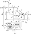
FIG. 2 is schematic view of the ECS ofFIG. 1 , showing a controller controlling an ECS output air flow using an outer control loop module and an inner control loop module operatively connected to a flow control valve; -
FIG. 3 is a schematic view of the outer control loop module and the inner control loop module of the ECS, showing inputs and outputs of the outer control loop module and the inner control loop module, respectively; and -
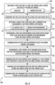
FIG. 4 is process flow diagram of a method of controlling air flow through an ECS, showing steps of the method. - A detailed description of one or more embodiments of the disclosed apparatus and method are presented herein by way of exemplification and not limitation with reference to the Figures.
- Reference will now be made to the drawings wherein like reference numerals identify similar structural features or aspects of the subject disclosure. For purposes of explanation and illustration, and not limitation, a partial view of an exemplary embodiment of an environmental control system (ECS) in accordance with the disclosure is shown in
FIG. 1 and is designated generally byreference character 100. Other embodiments of methods of controlling airflow through environmental control systems, environmental control systems, and computer program products for controlling flow through environmental control systems in accordance with the disclosure, or aspects thereof, are provided inFIGS. 2-4 , as will be described. The systems and methods described herein can be used for environmental control systems supplied air from two or more sources, such as compressed bleed air from a gas turbine engine compressor section and uncompressed ambient air from the external environment, through the present disclosure is not limited to environmental air control systems employing ambient air flows or to aircraft environmental control systems in general. - Referring to
FIG. 1 , anaircraft 10 is shown. Theaircraft 10 includes anenclosure 12 containing acabin 14, agas turbine engine 16, and the ECS 100. Theenclosure 12 encloses thecabin 14 such that the environment within thecabin 14 can be maintained to within a predetermined pressure and temperature range. To maintain pressure and temperature within thecabin 14 within the predetermined pressure and temperature range the ECS 100 provides an ECSoutput air flow 18 to thecabin 14. Thecabin 14 can enclose, for example, a portion of an aircraft fuselage housing the aircraft flight deck, a crew space, and/or a passenger space of theaircraft 10. - The
gas turbine engine 16 includes aturbine section 20, acompressor section 22, and ableed valve 24. Theturbine section 20 is configured to extract work by expanding a working fluid flow provided thereto. Thecompressor section 22 is configured to ingest ambient air from theexternal environment 26, compress the ingested ambient air using work provided by theturbine section 20 to form a compressed gas flow, and communicate the compressed gas flow to a combustion section to generate the working fluid flow provided to theturbine section 20. The bleedvalve 24 connects the ECS 100 to thecompressor section 22 and is configured to provide a portion of the compressed gas flow to theECS 100 as afirst air flow 30, e.g., a bleed air flow, to theECS 100. - The
ECS 100 receives both thefirst air flow 30 and asecond air flow 34, e.g., an uncompressed ambient air flow, from anambient air intake 32 carried by theaircraft 10, which is in fluid communication with the ambientexternal environment 26 outside theaircraft 10. TheECS 100 combines thesecond air flow 34 with thefirst air flow 30 and provides the combined flow an ECSoutput air flow 18 to theenclosure 12. While shown and described herein with thecompressor section 22 of thegas turbine engine 16, it is to be understood and appreciated that other sources of pressurized gas can be employed and remain within the scope of the present disclosure, such as gas bottles, ground cart-mounted compressors, fan air, and/or ram air, as suitable for an intended application. - With reference to
FIG. 2 , theECS 100 is shown. TheECS 100 includes afirst air conduit 102, asecond air conduit 104, and aflow control valve 106. TheECS 100 also includes aturbine 108, acompressor 110, and acontroller 112. Thefirst air conduit 102 connects thebleed valve 24 to theenclosure 12 through theflow control valve 106 andturbine 108, theflow control valve 106 arranged between thebleed valve 24 and theturbine 108. In this respect theturbine 108 has aturbine inlet 114 and aturbine outlet 116, theturbine outlet 116 connected to theflow control valve 106 through theturbine inlet 114. - The
second air conduit 104 connects theambient air intake 32 to thecompressor 110, and therethrough to theenclosure 12 through thefirst air conduit 102. In this respect thecompressor 110 has acompressor inlet 118 and acompressor outlet 120. Theambient air intake 32 is connected to thecompressor inlet 118, and therethrough to thecompressor outlet 120. Aunion 122 is located downstream of both thecompressor outlet 120 and theturbine outlet 116, theunion 122 connecting thesecond air conduit 104 to thefirst air conduit 102. Thefirst air flow 30 and thesecond air flow 34 combine at theunion 122 to form the ECSoutput air flow 18, which theECS 100 provides to theenclosure 12. - The
turbine 108 is configured to extractwork 121 from thefirst air flow 30 as thefirst air flow 30 traverses theturbine 108, and is the operatively connected to thecompressor 110. Connection of theturbine 108 to thecompressor 110 can be, for example, via one or more of a shaft 123, a gear 124, a chain 126, and/or a belt 128, as suitable for an intended application. As will be appreciated by those of skill in the art in view of the present disclosure, operative connection of theturbine 108 to thecompressor 110 enables theturbine 108 to power thecompressor 110 usingwork 121 extracted from thefirst air flow 30 as thefirst air flow 30 traverses theturbine 108. This limits the efficiency loss associated with bleeding a portion of the compressed gas flow generated by the compressor section 22 (shown inFIG. 1 ) of the gas turbine engine 16 (shown inFIG. 1 ) as thefirst air flow 30. - The
compressor 110 is configured to compress thesecond air flow 34 as thesecond air flow 34 traverses thecompressor 110. More specifically, thecompressor 110 compresses thesecond air flow 34 as thesecond air flow 34 traverses thecompressor 110 according to the amount ofwork 121 communicated to thecompressor 110 by theturbine 108. The amount ofwork 121 communicated to thecompressor 110 by theturbine 108 in turn depends upon the mass flow rate offirst air flow 30 provided to theturbine 108 by thefirst air conduit 102. The actual mass flow rate offirst air flow 30 provided to theECS 100 during operation is in turn controlled by theflow control valve 106. - The
flow control valve 106 is configured and adapted for modulating, i.e., increasing or decreasing, the mass flow rate of thefirst air flow 30 according to a flow controlvalve command signal 130 received from thecontroller 112. As will be appreciated by those of skill in the art in view of the present disclosure, changing mass flow rate of thefirst air flow 30 changes the mass flow rate of thesecond air flow 34 according to the change inwork 121 extracted by theturbine 108 from thefirst air flow 30. In this respect theflow control valve 106 is operatively associated with thecontroller 112, for example, through acommunication link 132 connecting thecontroller 112 to theflow control valve 106. It is contemplated that thecommunication link 132 can be wired, wireless, analog, and/or digital, as suitable for an intended application. - The
controller 112 includes aprocessor 134, adevice interface 136, and amemory 138. Thememory 138 includes a non-transitory machine-readable medium having a plurality of program modules 140 recorded on thememory 138. The plurality of program modules 140 have instructions that, when read by theprocessor 134, cause thecontroller 112 to execute certain operations. Among those operations include the operations of a method 200 (shown inFIG. 4 ) of controlling air flow through theECS 100. In the is respect the plurality of program modules 140 include an outercontrol loop module 142 cascaded with an innercontrol loop module 143 for controlling, e.g., regulating, the mass flow rate of thefirst air flow 30 and thesecond air flow 34 through thefirst air conduit 102 and thesecond air conduit 104, respectively. Control is effected by the flow controlvalve command signal 130, which is generated by thecontroller 112 using the outercontrol loop module 142 and the cascaded innercontrol loop module 143, and which is based on a firstair flow measurement 158 and one of a combinedflow measurement 144 and a combinedflow measurement 184. In certain embodiments, thememory 138 can have recorded on it a targettotal flow value 148, which is the desired value of total flow from theECS 100. - The first
air flow measurement 158 is provided by a firstair flow sensor 160. The firstair flow sensor 160 is in communication with thefirst air conduit 102 at a location between thebleed valve 24 and theturbine 108, and is arranged to provide the firstair flow measurement 158 to thecontroller 112. - In certain embodiments the combined
flow measurement 144 is provided by an ECS outputair flow sensor 156. It is contemplated that the ECS outputair flow sensor 156 be in communication with thefirst air conduit 102 at a location between theunion 122 and theenclosure 12. This allows a single ECS output air flow sensor to provide the combinedflow measurement 144 using a single ECS output flow sensor. - In accordance with certain embodiments, the combined
flow measurement 184 can be a sum of a firstair flow measurement 158 and a secondair flow measurement 182. It is contemplated that the secondair flow measurement 182 can be provided a secondair flow sensor 178 in communication with thesecond air conduit 104 at a location betweenunion 122 and thecompressor 110, and arranged to provide the secondair flow measurement 182 to the controller based on thesecond air flow 34. As shown inFIG. 2 the firstair flow measurement 158 and the secondair flow measurement 182 are added to one another in a summingmodule 180, which add the firstair flow measurement 158 to the secondair flow measurement 182 to generate the combinedflow measurement 184. - During operation of the
ECS 100 employees theflow control valve 106, and in certain embodiments in accordance with the present invention not more than the singleflow control valve 106, to control both thefirst air flow 30 provided by thecompressor section 22 and thesecond air flow 34 provided by theambient air intake 32. For example, in certain embodiments theflow control valve 106 operates like a butterfly valve to increase or reduce thefirst air flow 30. As will be appreciated by those of skill in the art in view of the present disclosure, increase in thefirst air flow 30 increases the amount ofwork 121 applied to thecompressor 110 by theturbine 108, which in turn increases the mass flow of thesecond air flow 34. Oppositely, decrease in thefirst air flow 30 decreases the amount ofwork 121 applied to thecompressor 110 by theturbine 108, decreasing the mass flow of thesecond air flow 34. As will be also appreciated by those of skill in the art in view of the present disclosure, the mass flow rate of thefirst air flow 30 is controlled by theflow control valve 106 and dictates the mass flow rates of both thefirst air flow 30 and thesecond air flow 34 according modulation of the singleflow control valve 106. Modulation of the singularflow control valve 106 is controlled by thecontroller 112 via the outercontrol loop module 142 and the innercontrol loop module 143. - With reference to
FIG. 3 ,controller 112 is shown in a logic diagram. Thecontroller 112 includes the innercontrol loop module 143 cascaded with the outercontrol loop module 142. The outercontrol loop module 142 includes a proportionintegral (PI)control algorithm 170 and is configured to receive a targettotal flow value 166 and a combined flow measurement. As shown inFIG. 3 the targettotal flow value 166 is received from thememory 138 and the combinedflow measurement 144 is received from the ECS outputair flow sensor 156. It is to be understood and appreciated that outercontrol loop module 142 can received the combined flow measurement 184 (shown inFIG. 2 ). Based on the targettotal flow value 166 and the combinedflow measurement 144 the outercontrol loop module 142 determine a first airflow reference value 168, which the outercontrol loop module 142 communicates to the innercontrol loop module 143. - The inner
control loop module 142 includes aPI control algorithm 176 and is configured to receive the first airflow reference value 168 and the firstair flow measurement 158, e.g., a bleed air flow measurement. The first airflow reference value 168 is received from the outercontrol loop module 142 and the firstair flow measurement 158 is received from the firstair flow sensor 160. Based on the first airflow reference value 168 and the firstair flow measurement 158 the innercontrol loop module 143 determines the flow controlvalve command signal 130, which the innercontrol loop module 143 communicates to theflow control valve 106. Advantageously, employment of thePI control algorithm 170 and/or thePI control algorithm 176 provide a relatively slow response to change in either (or both) the first air flow 30 (shown inFIG. 1 ) and the ECS output air flow 18 (shown inFIG. 1 ), which tends to dampen high frequency changes in either (or both) thefirst air flow 30 and the ECSoutput air flow 18. - Referring now to
FIG. 4 , amethod 200 of controlling air flow in an ECS system, e.g., the ECS 100 (shown inFIG. 1 ), is shown. As shown withbox 202, themethod 200 includes receiving a first air flow at a first air conduit, e.g., the first air flow 30 (shown inFIG. 1 ) at the first air conduit 102 (shown inFIG. 2 ). The method also includes receiving a second air flow at a second air conduit, e.g., the second air flow 34 (shown inFIG. 1 ) at the second air conduit 104 (shown inFIG. 2 ). As shown withbox 204, it is contemplated that the first air flow can be a compressed bleed air flow. As shown withbox 206, it is also contemplated that the second air flow can be an uncompressed air flow. The first air flow and the second air flow are combined within the ECS to generate an ECS output air flow, e.g., the ECS output air flow 18 (shown inFIG. 1 ), as shown withbox 208. - As shown with
box 210, the method also includes receiving a target total flow value, e.g., the target total flow value 166 (shown inFIG. 3 ), at an outer control loop module, e.g., the outer control loop module 142 (shown inFIG. 3 ). A combined flow measurement, e.g., the combined flow measurement 144 (shown inFIG. 2 ) or the combined flow measurement 184 (shown inFIG. 2 ), is also received at the outer control loop module, as also shown withbox 210. It is contemplated that that the combined flow measurement be representative of the ECS output air flow, e.g., the ECS output air flow 18 (show inFIG. 1 ), as shown withbox 212. In certain embodiments the combined flow measurement is additionally determined from measurements acquired from the both the first air conduit and the second air conduits, e.g., by adding the first air flow measurement 158 (shown inFIG. 2 ) to the second air flow measurement 182 (shown inFIG. 2 ), as shown withbox 214. - As shown with
box 216, a first air flow reference value is determined based on the target total flow value and the combined flow measurement using the outer control loop module. The first air flow reference is communicated to an inner control loop module, e.g., the inner control loop module 143 (shown inFIG. 3 ), as shown withbox 218. It is contemplated that the first air flow reference value be determined using a PI-control algorithm, e.g., the PI-control algorithm 170 (shown inFIG. 3 ). - As shown with
box 220, a flow control valve command signal, e.g., the flow control valve command signal 130 (shown inFIG. 2 ). It is contemplated that the flow control valve command signal be determined based on the first air flow reference valve and a first air flow measurement, e.g., the first air flow measurement 158 (shown inFIG. 2 ), as also shown bybox 220. In certain embodiments the flow valve command signal can be determined using a PI control algorithm e.g., the PI control algorithm 176 (shown inFIG. 3 ). Further, the first air flow measurement can be a measurement of a bleed air flow carried by the first air conduit of the ECS. - As shown with
box 222, the flow control valve command signal is communicated to a flow control valve, e.g., the flow control valve 106 (shown inFIG. 2 ), operatively associated with the inner control loop module. Based on the flow control valve signal the flow control valve changes air flow through both the first air conduit and the second air conduit of the ECS, as shown withbox 224. The flows are thereafter combined and provided to an enclosure as the ECS output air flow, as show withbox 226. - While the above description has described the flow process of
FIG. 4 in a particular order, it should be appreciated that unless otherwise specifically required in the attached claims that the ordering of the steps may be varied. For example, the steps of themethod 200 need not occur in series as illustrated inFIG. 4 , the order of certain operations differing from that shown. - As described above, embodiments, such as the outer
control loop module 142 and the innercontrol loop module 143, can be in the form of processorimplemented processes and devices for practicing those processes, such as a processor and/or a memory. Embodiments can also be in the form of computer program code containing instructions embodied in tangible media, such as network cloud storage, SD cards, flash drives, floppy diskettes, CD ROMs, hard drives, or any other computer-readable storage medium, wherein, when the computer program code is loaded into and executed by a computer, the computer becomes a device for practicing the embodiments. Embodiments can also be in the form of computer program code, for example, whether stored in a storage medium, loaded into and/or executed by a computer, or transmitted over some transmission medium, loaded into and/or executed by a computer, or transmitted over some transmission medium, such as over electrical wiring or cabling, through fiber optics, or via electromagnetic radiation, wherein, when the computer program code is loaded into and executed by a computer, the computer becomes a device for practicing the embodiments. When implemented on a general-purpose microprocessor, the computer program code segments configure the microprocessor to create specific logic circuits. - The term "about" is intended to include the degree of error associated with measurement of the particular quantity based upon the equipment available at the time of filing the application. For example, "about" can include a range of ± 8% or 5%, or 2% of a given value.
- The terminology used herein is for the purpose of describing particular embodiments only and is not intended to be limiting of the present disclosure. As used herein, the singular forms "a", "an" and "the" are intended to include the plural forms as well, unless the context clearly indicates otherwise. It will be further understood that the terms "comprises" and/or "comprising," when used in this specification, specify the presence of stated features, integers, steps, operations, elements, and/or components, but do not preclude the presence or addition of one or more other features, integers, steps, operations, element components, and/or groups thereof.
- While the present disclosure has been described with reference to an exemplary embodiment or embodiments, it will be understood by those skilled in the art that various changes may be made for elements thereof without departing from the scope of the present disclosure. In addition, many modifications may be made to adapt a particular situation or material to the teachings of the present disclosure without departing from the essential scope thereof. Therefore, it is intended that the present disclosure not be limited to the particular embodiment disclosed as the best mode contemplated for carrying out this present disclosure, but that the present disclosure will include all embodiments falling within the scope of the claims.
Claims (14)
- A method of controlling air flow in an environmental control system , ECS, of an aircraft;wherein the ECS (100) receives a first air flow (30) from a compressor section (22) of an aircraft engine of aircraft (10) and a second airflow from an uncompressed ambient air intake (32);wherein a flow control valve (106) controls both the first air flow (30) provided by the compressor section (22) and the second air flow (34) provided by the ambient air intake (32);wherein: a first air conduit (102) connects the compressor section (22) to an enclosure (12) of the aircraft through the flow control valve (106) and turbine (108) of the ECS; and a second air conduit (104) connects the ambient air intake to a compressor (110) of the ECS and therethrough to the enclosure (12); and a union (122) is located downstream of both the compressor outlet (120) and the turbine outlet (116), wherein the union (122) connects the second air conduit (104) to the first air conduit (102), to combined the first air flow (30) and the second air flow (34) to form ECS output air flow (18), which is provided to the enclosure (12);wherein an ECS output air flow sensor (156) is in communication with the first air conduit (103) between the union and the enclosure (12) and provides a combined flow measurement (144);wherein the flow control valve (106) is configured for modulating a mass flow rate of the first air flow (30) according to a flow control valve command signal (130) received from a controller (112) of the ECS; andwherein the controller (112) includes a processor (134) and a memory (138) with a plurality of program modules (140) recorded thereon, the plurality of program modules (140) include an outer control loop module (142) cascaded with an inner control loop module (143) for modulating the mass flow rate of the first air flow (30) and the second air flow (34) through the first air conduit (102) and the second air conduit (104) respectively, the method comprising:receiving a target total flow value (148), representing the desire value of the total flow from the ECS, and a combined flow measurement (144) at the outer control loop module (142);determining a first air flow reference value (168) based on the target total flow value (148) and the combined flow measurement (144) using the outer control loop module (142);communicating the first air flow reference value (168) to the inner control loop module (143);determining the flow control valve command signal (130) based at least in part on the first air flow reference value (168) using the inner control loop module (143); andcommunicating the flow control valve command signal (130) to the flow control valve (106) operatively associated with the inner control loop module (143) to control the first air flow (30) through the first air conduit (102) and the second air flow (34) through the second air conduit (104) of the ECS;wherein the flow control valve is a single flow control valve so that the mass flow rate of the first air flow (30) is controlled by the flow control valve (106), which dictates the mass flow rates of both the first air flow (30) and the second air flow (34) according to modulation of the single flow control valve (106).
- The method as recited in claim 1, further comprising changing air flow through both the first air conduit (102) and the second air conduit (103) using the flow control valve.
- The method as recited in claims 1 or 2, wherein receiving the combined flow measurement comprises receiving a measurement of ECS output air flow to an aircraft cabin.
- The method as recited in any preceding claim, wherein receiving the combined flow measurement comprises receiving a first air flow measurement and a second air flow measurement, the method further comprising adding the first air flow measurement to the second air flow measurement.
- The method as recited in any preceding claim, wherein the combined flow measurement indicates air flow through a bleed air conduit and an ambient air conduit of the ECS.
- The method as recited in any preceding claim, wherein determining the first air flow reference value comprises employing a proportional-integral control algorithm, and/or
wherein determining the flow control valve command comprises employing a proportional-integral control algorithm. - An environmental control system, comprising:a first air conduit (102) and a second air conduit (104);a turbine (108) in fluid communication with the first air conduit (102);a compressor (110) in fluid communication with the second air conduit (104), wherein the compressor (110) is operatively associated with the turbine (108);a flow control valve (106) arranged along the first air conduit; anda controller (112) having an inner control loop module (143) cascaded with an outer control loop module (142), the controller (112) operatively connected to the flow control valve (106) and responsive to instructions recorded on a memory to:receive a target total flow value and a combined flow measurement at the outer control loop module (142);determine a first air flow reference value based on the target total flow value and the combined flow measurement using the outer control loop module (142);communicate the first air flow reference value to the inner control loop module (143);determine a flow control valve command based at least in part on the first air flow reference value using the inner control loop module (143); andcommunicate the flow control valve command to the flow control valve (106);wherein the flow control valve is a single flow control valve so that a mass flow rate of a first air flow (30) is controlled by the flow control valve (106), which dictates the mass flow rates of both the first air flow (30) and a second air flow (34) according to modulation of the single flow control valve (106).
- The environmental control system as recited in claim 7, further comprising a compressor section of a gas turbine engine connected to the first air conduit by a bleed valve.
- The environmental control system as recited in claims 7 or 8, further comprising an ambient air intake connected to the second air conduit (104).
- The environmental control system as recited in any of claims 7 to 9, further comprising a union connecting the second air conduit (104) to the first air conduit (102).
- The environmental control system as recited in claim 10, wherein the turbine (108) has a turbine outlet, wherein the union is arranged downstream of the turbine outlet; and/orwherein the compressor (110) has a compressor outlet, wherein the union is arranged downstream of the compressor outlet; and/orfurther comprising a combined flow sensor arranged between the union and an enclosure connected to the ECS; and/orfurther comprising:a first air flow sensor in communication with the first air conduit, the first air sensor arranged to provide a first air flow measurement of a first air flow in the first air conduit (102); anda second air flow sensor in communication with the second air conduit, the second air flow sensor arranged to provide a second air flow measurement of a second air flow in the second air conduit (104),wherein the instructions further cause the controller (112) to provide the combined flow measurement to the outer control module by adding the first air flow measurement to the second air flow measurement.
- The environmental control system as recited in claim 7, further comprising a first air flow sensor in communication with the first air conduit (102) and arranged provide the first air flow measurement to the inner control module (143).
- The environmental control system as recited in any of claims 7 to 12, wherein the outer control loop module (142) comprises a proportional-integral control algorithm, wherein the inner control loop module (143) comprises a proportional-integral control algorithm.
- A computer program product tangibly embodied on a computer readable medium, the computer program product including instructions that, when executed by a processor, cause the processor to perform operations comprising:receiving a target total flow value at an outer control loop module (142);receiving a combined flow measurement at the outer control loop module (142);determining a first air flow reference value based on the target total flow value and the combined flow measurement using the outer control loop module (142);communicating the first air flow reference value to an inner control loop module (143);determining a flow control valve command based at least in part on the first air flow reference value using the inner control loop module (143); andcommunicating the flow control valve command to a flow control valve operatively associated with the inner control loop module (143);wherein the flow control valve is a single flow control valve so that a mass flow rate of the first air flow (30) is controlled by the flow control valve (106), which dictates the mass flow rates of both the first air flow (30) and a second air flow (34) according to modulation of the single flow control valve (106).
Applications Claiming Priority (1)
| Application Number | Priority Date | Filing Date | Title |
|---|---|---|---|
| US16/271,507 US11434010B2 (en) | 2019-02-08 | 2019-02-08 | Environmental control systems and methods of controlling airflow through environmental control systems |
Publications (2)
| Publication Number | Publication Date |
|---|---|
| EP3693276A1 EP3693276A1 (en) | 2020-08-12 |
| EP3693276B1 true EP3693276B1 (en) | 2022-03-23 |
Family
ID=68618046
Family Applications (1)
| Application Number | Title | Priority Date | Filing Date |
|---|---|---|---|
| EP19210056.8A Active EP3693276B1 (en) | 2019-02-08 | 2019-11-19 | Environmental control systems and methods of controlling airflow through environmental control systems |
Country Status (2)
| Country | Link |
|---|---|
| US (1) | US11434010B2 (en) |
| EP (1) | EP3693276B1 (en) |
Family Cites Families (12)
| Publication number | Priority date | Publication date | Assignee | Title |
|---|---|---|---|---|
| US5145124A (en) | 1990-07-12 | 1992-09-08 | Allied-Signal Inc. | Fluid conditioning system and apparatus |
| US6070418A (en) | 1997-12-23 | 2000-06-06 | Alliedsignal Inc. | Single package cascaded turbine environmental control system |
| GB201410180D0 (en) * | 2014-06-09 | 2014-07-23 | Rolls Royce Plc | Method and apparatus for controlling a compressor of a gas turbine engine |
| US9957052B2 (en) * | 2015-01-27 | 2018-05-01 | Honeywell International Inc. | Aircraft environmental control system that optimizes the proportion of outside air from engines, APU's, ground air sources and the recirculated cabin air to maintain occupant comfort and maximize fuel economy |
| US10794295B2 (en) | 2016-03-15 | 2020-10-06 | Hamilton Sunstrand Corporation | Engine bleed system with multi-tap bleed array |
| US9896216B2 (en) | 2016-06-01 | 2018-02-20 | Honeywell Limited | ECO mode ECS logic |
| US11377216B2 (en) * | 2016-08-23 | 2022-07-05 | Ge Aviation Systems Llc | Advanced method and aircraft for pre-cooling an environmental control system using a dual compressor four wheel turbo-machine |
| US20180057171A1 (en) * | 2016-08-23 | 2018-03-01 | Ge Aviation Systems, Llc | Advanced method and aircraft for pre-cooling an environmental control system using a three wheel turbo-machine |
| US20180057170A1 (en) * | 2016-08-23 | 2018-03-01 | Ge Aviation Systems, Llc | Enhanced method and aircraft for pre-cooling an environmental control system using a two wheel turbo-machine with supplemental heat exchanger |
| US10414505B2 (en) * | 2016-09-02 | 2019-09-17 | Embraer S.A. | Aircraft air conditioning system airflow regulation |
| US10882623B2 (en) * | 2017-01-27 | 2021-01-05 | Hamilton Sunstrand Corporation | Advanced environmental control system in an integrated split pack arrangement with two bleed/outflow heat exchangers |
| US11161616B2 (en) * | 2017-04-27 | 2021-11-02 | Textron Innovations, Inc. | High efficiency pneumatic flow control system for aircraft |
-
2019
- 2019-02-08 US US16/271,507 patent/US11434010B2/en active Active
- 2019-11-19 EP EP19210056.8A patent/EP3693276B1/en active Active
Also Published As
| Publication number | Publication date |
|---|---|
| EP3693276A1 (en) | 2020-08-12 |
| US20200255153A1 (en) | 2020-08-13 |
| US11434010B2 (en) | 2022-09-06 |
Similar Documents
| Publication | Publication Date | Title |
|---|---|---|
| EP3907388B1 (en) | Engine bleed power recovery systems and related methods | |
| US10745136B2 (en) | Environmental control system including a compressing device | |
| EP3401223B1 (en) | Motor cooling utilizing cabin air | |
| EP3095702B1 (en) | Environmental control system utilizing cabin discharge air to power a cycle | |
| EP2937287B1 (en) | Environmental control systems utilizing shoestring cycle to maximize efficiency | |
| US7828874B2 (en) | On-board inert gas generation system with air separation module temperature control | |
| US9623974B2 (en) | Aircraft environmental control system and method | |
| EP3002431B1 (en) | Engine bleed air system | |
| US20130133334A1 (en) | Cooling system for engine and aircraft air | |
| EP2829706A1 (en) | Bleed air systems for use with aircrafts and related methods | |
| EP3620378B1 (en) | Air-driven vapor cycle refrigeration system | |
| EP2842872A1 (en) | Bleed air system | |
| EP2476618B1 (en) | Integrated bleed and engine controller | |
| EP3103721B1 (en) | Recirculation system for parallel ram heat exchangers | |
| EP3712414B1 (en) | Compressed air system | |
| US20130139521A1 (en) | On board inert gas generation system | |
| EP3587268B1 (en) | Simultaneous dual engine bleed thermal management system | |
| EP3693276B1 (en) | Environmental control systems and methods of controlling airflow through environmental control systems | |
| US2959029A (en) | Air conditioning system | |
| EP3693277A1 (en) | Environmental control systems and methods of controlling air flow through environmental control systems | |
| EP3064434B1 (en) | Aircraft having replacement system providing replacement air to an inerting system | |
| US6640560B2 (en) | Distributed electronic control for air conditioning system | |
| US20240280059A1 (en) | System and Method to Prevent Bleed Air Over-Extraction in Aircraft |
Legal Events
| Date | Code | Title | Description |
|---|---|---|---|
| PUAI | Public reference made under article 153(3) epc to a published international application that has entered the european phase |
Free format text: ORIGINAL CODE: 0009012 |
|
| STAA | Information on the status of an ep patent application or granted ep patent |
Free format text: STATUS: THE APPLICATION HAS BEEN PUBLISHED |
|
| AK | Designated contracting states |
Kind code of ref document: A1 Designated state(s): AL AT BE BG CH CY CZ DE DK EE ES FI FR GB GR HR HU IE IS IT LI LT LU LV MC MK MT NL NO PL PT RO RS SE SI SK SM TR |
|
| AX | Request for extension of the european patent |
Extension state: BA ME |
|
| STAA | Information on the status of an ep patent application or granted ep patent |
Free format text: STATUS: REQUEST FOR EXAMINATION WAS MADE |
|
| 17P | Request for examination filed |
Effective date: 20210204 |
|
| RBV | Designated contracting states (corrected) |
Designated state(s): AL AT BE BG CH CY CZ DE DK EE ES FI FR GB GR HR HU IE IS IT LI LT LU LV MC MK MT NL NO PL PT RO RS SE SI SK SM TR |
|
| GRAP | Despatch of communication of intention to grant a patent |
Free format text: ORIGINAL CODE: EPIDOSNIGR1 |
|
| STAA | Information on the status of an ep patent application or granted ep patent |
Free format text: STATUS: GRANT OF PATENT IS INTENDED |
|
| INTG | Intention to grant announced |
Effective date: 20211027 |
|
| GRAS | Grant fee paid |
Free format text: ORIGINAL CODE: EPIDOSNIGR3 |
|
| GRAA | (expected) grant |
Free format text: ORIGINAL CODE: 0009210 |
|
| STAA | Information on the status of an ep patent application or granted ep patent |
Free format text: STATUS: THE PATENT HAS BEEN GRANTED |
|
| AK | Designated contracting states |
Kind code of ref document: B1 Designated state(s): AL AT BE BG CH CY CZ DE DK EE ES FI FR GB GR HR HU IE IS IT LI LT LU LV MC MK MT NL NO PL PT RO RS SE SI SK SM TR |
|
| REG | Reference to a national code |
Ref country code: GB Ref legal event code: FG4D |
|
| REG | Reference to a national code |
Ref country code: CH Ref legal event code: EP |
|
| REG | Reference to a national code |
Ref country code: IE Ref legal event code: FG4D |
|
| REG | Reference to a national code |
Ref country code: DE Ref legal event code: R096 Ref document number: 602019012783 Country of ref document: DE |
|
| REG | Reference to a national code |
Ref country code: AT Ref legal event code: REF Ref document number: 1477281 Country of ref document: AT Kind code of ref document: T Effective date: 20220415 |
|
| REG | Reference to a national code |
Ref country code: LT Ref legal event code: MG9D |
|
| REG | Reference to a national code |
Ref country code: NL Ref legal event code: MP Effective date: 20220323 |
|
| PG25 | Lapsed in a contracting state [announced via postgrant information from national office to epo] |
Ref country code: SE Free format text: LAPSE BECAUSE OF FAILURE TO SUBMIT A TRANSLATION OF THE DESCRIPTION OR TO PAY THE FEE WITHIN THE PRESCRIBED TIME-LIMIT Effective date: 20220323 Ref country code: RS Free format text: LAPSE BECAUSE OF FAILURE TO SUBMIT A TRANSLATION OF THE DESCRIPTION OR TO PAY THE FEE WITHIN THE PRESCRIBED TIME-LIMIT Effective date: 20220323 Ref country code: NO Free format text: LAPSE BECAUSE OF FAILURE TO SUBMIT A TRANSLATION OF THE DESCRIPTION OR TO PAY THE FEE WITHIN THE PRESCRIBED TIME-LIMIT Effective date: 20220623 Ref country code: LT Free format text: LAPSE BECAUSE OF FAILURE TO SUBMIT A TRANSLATION OF THE DESCRIPTION OR TO PAY THE FEE WITHIN THE PRESCRIBED TIME-LIMIT Effective date: 20220323 Ref country code: HR Free format text: LAPSE BECAUSE OF FAILURE TO SUBMIT A TRANSLATION OF THE DESCRIPTION OR TO PAY THE FEE WITHIN THE PRESCRIBED TIME-LIMIT Effective date: 20220323 Ref country code: BG Free format text: LAPSE BECAUSE OF FAILURE TO SUBMIT A TRANSLATION OF THE DESCRIPTION OR TO PAY THE FEE WITHIN THE PRESCRIBED TIME-LIMIT Effective date: 20220623 |
|
| REG | Reference to a national code |
Ref country code: AT Ref legal event code: MK05 Ref document number: 1477281 Country of ref document: AT Kind code of ref document: T Effective date: 20220323 |
|
| PG25 | Lapsed in a contracting state [announced via postgrant information from national office to epo] |
Ref country code: LV Free format text: LAPSE BECAUSE OF FAILURE TO SUBMIT A TRANSLATION OF THE DESCRIPTION OR TO PAY THE FEE WITHIN THE PRESCRIBED TIME-LIMIT Effective date: 20220323 Ref country code: GR Free format text: LAPSE BECAUSE OF FAILURE TO SUBMIT A TRANSLATION OF THE DESCRIPTION OR TO PAY THE FEE WITHIN THE PRESCRIBED TIME-LIMIT Effective date: 20220624 Ref country code: FI Free format text: LAPSE BECAUSE OF FAILURE TO SUBMIT A TRANSLATION OF THE DESCRIPTION OR TO PAY THE FEE WITHIN THE PRESCRIBED TIME-LIMIT Effective date: 20220323 |
|
| PG25 | Lapsed in a contracting state [announced via postgrant information from national office to epo] |
Ref country code: NL Free format text: LAPSE BECAUSE OF FAILURE TO SUBMIT A TRANSLATION OF THE DESCRIPTION OR TO PAY THE FEE WITHIN THE PRESCRIBED TIME-LIMIT Effective date: 20220323 |
|
| PG25 | Lapsed in a contracting state [announced via postgrant information from national office to epo] |
Ref country code: SM Free format text: LAPSE BECAUSE OF FAILURE TO SUBMIT A TRANSLATION OF THE DESCRIPTION OR TO PAY THE FEE WITHIN THE PRESCRIBED TIME-LIMIT Effective date: 20220323 Ref country code: SK Free format text: LAPSE BECAUSE OF FAILURE TO SUBMIT A TRANSLATION OF THE DESCRIPTION OR TO PAY THE FEE WITHIN THE PRESCRIBED TIME-LIMIT Effective date: 20220323 Ref country code: RO Free format text: LAPSE BECAUSE OF FAILURE TO SUBMIT A TRANSLATION OF THE DESCRIPTION OR TO PAY THE FEE WITHIN THE PRESCRIBED TIME-LIMIT Effective date: 20220323 Ref country code: PT Free format text: LAPSE BECAUSE OF FAILURE TO SUBMIT A TRANSLATION OF THE DESCRIPTION OR TO PAY THE FEE WITHIN THE PRESCRIBED TIME-LIMIT Effective date: 20220725 Ref country code: ES Free format text: LAPSE BECAUSE OF FAILURE TO SUBMIT A TRANSLATION OF THE DESCRIPTION OR TO PAY THE FEE WITHIN THE PRESCRIBED TIME-LIMIT Effective date: 20220323 Ref country code: EE Free format text: LAPSE BECAUSE OF FAILURE TO SUBMIT A TRANSLATION OF THE DESCRIPTION OR TO PAY THE FEE WITHIN THE PRESCRIBED TIME-LIMIT Effective date: 20220323 Ref country code: CZ Free format text: LAPSE BECAUSE OF FAILURE TO SUBMIT A TRANSLATION OF THE DESCRIPTION OR TO PAY THE FEE WITHIN THE PRESCRIBED TIME-LIMIT Effective date: 20220323 Ref country code: AT Free format text: LAPSE BECAUSE OF FAILURE TO SUBMIT A TRANSLATION OF THE DESCRIPTION OR TO PAY THE FEE WITHIN THE PRESCRIBED TIME-LIMIT Effective date: 20220323 |
|
| PG25 | Lapsed in a contracting state [announced via postgrant information from national office to epo] |
Ref country code: PL Free format text: LAPSE BECAUSE OF FAILURE TO SUBMIT A TRANSLATION OF THE DESCRIPTION OR TO PAY THE FEE WITHIN THE PRESCRIBED TIME-LIMIT Effective date: 20220323 Ref country code: IS Free format text: LAPSE BECAUSE OF FAILURE TO SUBMIT A TRANSLATION OF THE DESCRIPTION OR TO PAY THE FEE WITHIN THE PRESCRIBED TIME-LIMIT Effective date: 20220723 Ref country code: AL Free format text: LAPSE BECAUSE OF FAILURE TO SUBMIT A TRANSLATION OF THE DESCRIPTION OR TO PAY THE FEE WITHIN THE PRESCRIBED TIME-LIMIT Effective date: 20220323 |
|
| REG | Reference to a national code |
Ref country code: DE Ref legal event code: R097 Ref document number: 602019012783 Country of ref document: DE |
|
| PLBE | No opposition filed within time limit |
Free format text: ORIGINAL CODE: 0009261 |
|
| STAA | Information on the status of an ep patent application or granted ep patent |
Free format text: STATUS: NO OPPOSITION FILED WITHIN TIME LIMIT |
|
| PG25 | Lapsed in a contracting state [announced via postgrant information from national office to epo] |
Ref country code: DK Free format text: LAPSE BECAUSE OF FAILURE TO SUBMIT A TRANSLATION OF THE DESCRIPTION OR TO PAY THE FEE WITHIN THE PRESCRIBED TIME-LIMIT Effective date: 20220323 |
|
| 26N | No opposition filed |
Effective date: 20230102 |
|
| PG25 | Lapsed in a contracting state [announced via postgrant information from national office to epo] |
Ref country code: SI Free format text: LAPSE BECAUSE OF FAILURE TO SUBMIT A TRANSLATION OF THE DESCRIPTION OR TO PAY THE FEE WITHIN THE PRESCRIBED TIME-LIMIT Effective date: 20220323 |
|
| PG25 | Lapsed in a contracting state [announced via postgrant information from national office to epo] |
Ref country code: MC Free format text: LAPSE BECAUSE OF FAILURE TO SUBMIT A TRANSLATION OF THE DESCRIPTION OR TO PAY THE FEE WITHIN THE PRESCRIBED TIME-LIMIT Effective date: 20220323 |
|
| REG | Reference to a national code |
Ref country code: CH Ref legal event code: PL |
|
| P01 | Opt-out of the competence of the unified patent court (upc) registered |
Effective date: 20230603 |
|
| REG | Reference to a national code |
Ref country code: BE Ref legal event code: MM Effective date: 20221130 |
|
| PG25 | Lapsed in a contracting state [announced via postgrant information from national office to epo] |
Ref country code: LI Free format text: LAPSE BECAUSE OF NON-PAYMENT OF DUE FEES Effective date: 20221130 Ref country code: IT Free format text: LAPSE BECAUSE OF FAILURE TO SUBMIT A TRANSLATION OF THE DESCRIPTION OR TO PAY THE FEE WITHIN THE PRESCRIBED TIME-LIMIT Effective date: 20220323 Ref country code: CH Free format text: LAPSE BECAUSE OF NON-PAYMENT OF DUE FEES Effective date: 20221130 |
|
| PG25 | Lapsed in a contracting state [announced via postgrant information from national office to epo] |
Ref country code: LU Free format text: LAPSE BECAUSE OF NON-PAYMENT OF DUE FEES Effective date: 20221119 |
|
| PG25 | Lapsed in a contracting state [announced via postgrant information from national office to epo] |
Ref country code: IE Free format text: LAPSE BECAUSE OF NON-PAYMENT OF DUE FEES Effective date: 20221119 |
|
| PG25 | Lapsed in a contracting state [announced via postgrant information from national office to epo] |
Ref country code: BE Free format text: LAPSE BECAUSE OF NON-PAYMENT OF DUE FEES Effective date: 20221130 |
|
| PG25 | Lapsed in a contracting state [announced via postgrant information from national office to epo] |
Ref country code: CY Free format text: LAPSE BECAUSE OF FAILURE TO SUBMIT A TRANSLATION OF THE DESCRIPTION OR TO PAY THE FEE WITHIN THE PRESCRIBED TIME-LIMIT Effective date: 20220323 |
|
| PG25 | Lapsed in a contracting state [announced via postgrant information from national office to epo] |
Ref country code: MK Free format text: LAPSE BECAUSE OF FAILURE TO SUBMIT A TRANSLATION OF THE DESCRIPTION OR TO PAY THE FEE WITHIN THE PRESCRIBED TIME-LIMIT Effective date: 20220323 Ref country code: HU Free format text: LAPSE BECAUSE OF FAILURE TO SUBMIT A TRANSLATION OF THE DESCRIPTION OR TO PAY THE FEE WITHIN THE PRESCRIBED TIME-LIMIT; INVALID AB INITIO Effective date: 20191119 |
|
| PG25 | Lapsed in a contracting state [announced via postgrant information from national office to epo] |
Ref country code: TR Free format text: LAPSE BECAUSE OF FAILURE TO SUBMIT A TRANSLATION OF THE DESCRIPTION OR TO PAY THE FEE WITHIN THE PRESCRIBED TIME-LIMIT Effective date: 20220323 |
|
| PG25 | Lapsed in a contracting state [announced via postgrant information from national office to epo] |
Ref country code: MT Free format text: LAPSE BECAUSE OF FAILURE TO SUBMIT A TRANSLATION OF THE DESCRIPTION OR TO PAY THE FEE WITHIN THE PRESCRIBED TIME-LIMIT Effective date: 20220323 |
|
| PGFP | Annual fee paid to national office [announced via postgrant information from national office to epo] |
Ref country code: DE Payment date: 20251022 Year of fee payment: 7 |
|
| PGFP | Annual fee paid to national office [announced via postgrant information from national office to epo] |
Ref country code: GB Payment date: 20251023 Year of fee payment: 7 |
|
| PGFP | Annual fee paid to national office [announced via postgrant information from national office to epo] |
Ref country code: FR Payment date: 20251022 Year of fee payment: 7 |