EP3693170A1 - Sheet member conveyance apparatus and ink jet recording apparatus - Google Patents
Sheet member conveyance apparatus and ink jet recording apparatus Download PDFInfo
- Publication number
- EP3693170A1 EP3693170A1 EP17928060.7A EP17928060A EP3693170A1 EP 3693170 A1 EP3693170 A1 EP 3693170A1 EP 17928060 A EP17928060 A EP 17928060A EP 3693170 A1 EP3693170 A1 EP 3693170A1
- Authority
- EP
- European Patent Office
- Prior art keywords
- conveyance
- section
- mounting surface
- ventilation
- sheet member
- Prior art date
- Legal status (The legal status is an assumption and is not a legal conclusion. Google has not performed a legal analysis and makes no representation as to the accuracy of the status listed.)
- Granted
Links
Images


Classifications
-
- B—PERFORMING OPERATIONS; TRANSPORTING
- B41—PRINTING; LINING MACHINES; TYPEWRITERS; STAMPS
- B41J—TYPEWRITERS; SELECTIVE PRINTING MECHANISMS, i.e. MECHANISMS PRINTING OTHERWISE THAN FROM A FORME; CORRECTION OF TYPOGRAPHICAL ERRORS
- B41J11/00—Devices or arrangements of selective printing mechanisms, e.g. ink-jet printers or thermal printers, for supporting or handling copy material in sheet or web form
- B41J11/007—Conveyor belts or like feeding devices
-
- B—PERFORMING OPERATIONS; TRANSPORTING
- B41—PRINTING; LINING MACHINES; TYPEWRITERS; STAMPS
- B41J—TYPEWRITERS; SELECTIVE PRINTING MECHANISMS, i.e. MECHANISMS PRINTING OTHERWISE THAN FROM A FORME; CORRECTION OF TYPOGRAPHICAL ERRORS
- B41J11/00—Devices or arrangements of selective printing mechanisms, e.g. ink-jet printers or thermal printers, for supporting or handling copy material in sheet or web form
- B41J11/0085—Using suction for maintaining printing material flat
-
- B—PERFORMING OPERATIONS; TRANSPORTING
- B41—PRINTING; LINING MACHINES; TYPEWRITERS; STAMPS
- B41J—TYPEWRITERS; SELECTIVE PRINTING MECHANISMS, i.e. MECHANISMS PRINTING OTHERWISE THAN FROM A FORME; CORRECTION OF TYPOGRAPHICAL ERRORS
- B41J13/00—Devices or arrangements of selective printing mechanisms, e.g. ink-jet printers or thermal printers, specially adapted for supporting or handling copy material in short lengths, e.g. sheets
- B41J13/08—Conveyor bands or like feeding devices
-
- B—PERFORMING OPERATIONS; TRANSPORTING
- B41—PRINTING; LINING MACHINES; TYPEWRITERS; STAMPS
- B41J—TYPEWRITERS; SELECTIVE PRINTING MECHANISMS, i.e. MECHANISMS PRINTING OTHERWISE THAN FROM A FORME; CORRECTION OF TYPOGRAPHICAL ERRORS
- B41J2/00—Typewriters or selective printing mechanisms characterised by the printing or marking process for which they are designed
- B41J2/005—Typewriters or selective printing mechanisms characterised by the printing or marking process for which they are designed characterised by bringing liquid or particles selectively into contact with a printing material
- B41J2/01—Ink jet
Definitions
- the present invention relates to a sheet member conveyance apparatus and an ink jet recording apparatus.
- ink jet recording apparatuses for discharging ink to a sheet member, such as paper or a resin sheet, to form an image on the sheet member.
- a sheet member conveyance apparatus for conveying a sheet member by placing the sheet member on a mounting surface of a conveyance member that moves along a predetermined movement path (e.g., a conveyance belt that moves around a predetermined circuit path) is commonly used.
- a predetermined movement path e.g., a conveyance belt that moves around a predetermined circuit path
- An object of the present invention is to provide a sheet member conveyance apparatus and an ink jet recording apparatus capable of more reliably adsorbing a sheet member on a mounting surface.
- a sheet member conveyance apparatus includes:
- the invention according to claim 2 is the sheet member conveyance apparatus according to claim 1, wherein the ventilation member is provided in a range overlapping with the second section as seen in the direction perpendicular to the mounting surface, and the first section is ventilated along a ventilation path that does not pass through the ventilation member.
- the invention according to claim 3 is the sheet member conveyance apparatus according to claim 1, wherein
- the invention according to claim 4 is the sheet member conveyance apparatus according to claim 3, wherein
- the invention according to claim 5 is the sheet member conveyance apparatus according to any one of claims 1 to 4, wherein the ventilation member is constituted by a porous body.
- the invention according to claim 6 is the sheet member conveyance apparatus according to claim 3 or 4, wherein
- the invention according to claim 7 is the sheet member conveyance apparatus according to any one of claims 1 to 4, wherein the ventilation member is constituted by a plate provided with through holes penetrating in the direction perpendicular to the mounting surface.
- the invention according to claim 8 is the sheet member conveyance apparatus according to claim 3 or 4, wherein
- the invention according to claim 9 is the sheet member conveyance apparatus according to any one of claims 1 to 8, wherein
- the invention according to claim 10 is the sheet member conveyance apparatus according to claim 9, wherein
- the invention according to claim 11 is the sheet member conveyance apparatus according to claim 10, wherein the suction unit comprises:
- the invention according to claim 12 is the sheet member conveyance apparatus according to any one of claims 1 to 11, wherein
- the invention according to claim 13 is the sheet member conveyance apparatus according to any one of claims 1 to 9, wherein
- the invention according to claim 14 is the sheet member conveyance apparatus according to claim 13, wherein
- the invention according to claim 15 is an ink jet recording apparatus, comprising:
- the invention according to claim 16 is the ink jet recording apparatus according to claim 15, wherein
- the invention according to claim 17 is the ink jet recording apparatus according to claim 15 or 16, wherein
- Fig. 1 is a diagram illustrating a schematic configuration of an ink jet recording apparatus 1 according to an embodiment of the present invention.
- the ink jet recording apparatus 1 includes a recording medium supplier 10, an image recorder 20, a fixing unit 30, a recording medium ejector 40, and the like.
- the recording medium supplier 10 includes a mounting tray 11, medium carrier rollers 12 and the like.
- the mounting tray 11 is a plate-shaped member on which various kinds of recording medium P (sheet member), such as paper, cardboard, corrugated cardboard and a resin sheet, are piled up.
- the uppermost recording medium P on the mounting tray is sent to the image recorder 20 one by one.
- the mounting tray 11 is movable in the vertical direction. In accordance with, for example, the total weight of the placed recording media P, the uppermost recording medium P is kept at a position for sending the recording medium P to the image recorder 20.
- Medium carrier rollers 12 are rotatable rollers that sandwich the recording medium P from above and below, and send the uppermost recording medium P mounted on the mounting tray 11.
- the recording medium P is sent in a horizontal direction.
- a guide member for aligning the recording medium P to a predetermined position in a width direction perpendicular to the conveyance direction of the recording medium P (leftward in Fig. 1 ) is attached to the medium carrier rollers 12.
- the medium carrier rollers 12 send the recording medium P aligned in the width direction to the image recorder 20.
- the image recorder 20 discharges ink onto the recording medium P passed from the recording medium supplier 10 to form an image. After ink lands on the recording medium P to form an image, the recording medium P is sent to the fixing unit 30.
- the image recorder 20 comprises a medium conveyer 21 (second conveyer), a support suction unit 22, one or more (in this embodiment, four) print heads 23 that discharge ink (ink discharger), a press roller 24, and the like.
- the medium conveyer 21 comprises a conveyance belt 211, a drive roller 212, a driven roller 213, guide rollers 214, and a tension roller 215.
- the conveyance belt 211 of the medium conveyer 21 is an endless (circular) strip member.
- a steel belt is used in this embodiment.
- the steel belt is made of, for example, stainless steel such as SUS304 and SUS631 or aluminum alloy having thickness of about 0.3 mm
- the conveyance belt 211 is provided with vents which have the same opening shape and which penetrate between the external circumference and the internal circumference of the conveyance belt 211. Specifically, a large number (plurality) of circular vents having a diameter of about 0.5 mm are arranged at about 1.4 mm intervals so that the open ratio is about 20%. Air passes between the external circumference and the internal circumference.
- the conveyance belt 211 bridges between the drive roller 212 and the driven roller 213 (hereinafter, these rollers together are also referred to as conveyance rollers 212, 213).
- the external circumference on which the recording medium P is mounted (hereinafter, also referred to as a mounting surface) is movable along a circuit path around the conveyance rollers 212, 213.
- the drive roller 212 rotates in accordance with rotation driven by a conveyance motor 65 ( Fig. 2 )
- the conveyance belt 211 moves along the circuit path around the conveyance rollers 212, 213 in accordance with the speed and the rotation direction of the rotation of the drive roller 212.
- the drive roller 212 rotates counterclockwise on the plane of Fig.
- a flat surface (in this embodiment, a horizontal surface) of the support suction unit 22 (hereinafter referred to as a support surface) supports the internal circumference of the conveyance belt 211 (the surface that touches the conveyance rollers 212, 213) in a range within the conveyance section of the conveyance belt 211, the range including a portion where the mounting surface of the conveyance belt 211 faces an ink discharge surface of the print heads 23.
- the support surface of the support suction unit 22 consists of a plate-shaped vent member 223 constituted by a porous body having ventilation.
- the support suction unit 22 has a suction fan 62 ( Fig.
- Guide rollers 214 are provided respectively upstream and downstream from the support suction unit 22 in the conveyance direction. Two guide rollers 214 support the internal circumference of the conveyance belt 211 outside both edges of the support surface of the support suction unit 22. The guide rollers 214 respectively support the conveyance belt 211 at substantially the same height as the support surface of the support suction unit 22 to guide circumferential movement of the conveyance belt 211.
- the press roller 24 is rotatably provided at a position opposed to the upstream guide roller 214 across the conveyance belt 211. Upstream in the conveyance direction from a position on the recording medium P where ink is discharged, the press roller 24 presses down the recording medium P on the conveyance belt 211 at an appropriate pressure and guide the recording medium P along the conveyance belt 211. Thereby the recording medium P, which has been sent from the recording medium supplier 10, is prevented from separating from the conveyance belt 211. Especially, an edge of the recording medium P is prevented from warping (curling) so that the recording medium P is more reliably adsorbed.
- the press roller 24 may be configured such that the distance from the conveyance surface of the conveyance belt 211 is variable in accordance with the thickness or the like of the recording medium P to be conveyed.
- the tension roller 215 presses the conveyance belt 211 from the internal circumference side at a position between the two conveyance rollers 212, 213, that is, in the middle of movement of the conveyance belt 211 from the drive roller 212 to the driven roller 213.
- the vertical position of the tension roller 215 is adjustable at two different positions in the width direction, for example, at both edges.
- the tension roller 215 corrects meander caused by non-uniformity of tension on the conveyance belt 211 applied by the support suction section 22 and the like. Thereby the conveyance belt 211 and the recording medium P are properly moved in the conveyance direction.
- the print heads 23 are provided on the side opposite to the support suction unit 22 across the conveyance belt 211. On the side facing the conveyance belt 211, the print heads 23 have an ink discharge surface provided with nozzle openings. The print heads 23 discharge ink to the recording medium P which is transferred while being adsorbed on the mounting surface of the conveyance belt 211 by the support suction unit 22. Thus ink lands on the recording medium P.
- the print heads 23 have one or more recording heads 231 ( Fig. 2 ) in which nozzle openings are provided in a predetermined arrangement to perform an operation relating to ink discharge from the nozzle openings.
- a range in the width direction in which an image is formed on the recording medium P is within a range in the width direction in which the nozzles of the print heads 23 are arranged.
- the positions of the print heads 23 are fixed while an image is recorded. Ink is discharged sequentially on different positions in the conveyance direction at predetermined intervals (intervals in the conveyance direction) as the recording medium P is conveyed. Thereby an image is formed in a single-pass manner.
- the four print heads 23 are respectively connected to ink tanks (not shown) of colors cyan (C), magenta (M), yellow (Y) and black (K) to respectively discharge ink of these CMYK colors.
- the image recorder 20 may include a print head 23 for discharging ink other than these four colors, such as orange, green, violet, red, blue, white, or the like, or transparent ink.
- Ink that changes phase between gel and sol is used as ink discharged from the nozzles of the print heads 23.
- Gel is classified as solid while Sol is classified as liquid.
- ink that has been made gelatinous through heating is discharged from the nozzles of the print heads 23. After ink lands on the recording medium P, the ink is cooled down to be gelatinous rapidly, and solidifies on the recording medium P.
- ink that cures under ultraviolet rays (curable material) is used.
- Ink that contains a photopolymerizable compound (monomer), a photopolymerization initiator and a colorant are used as this kind of ink.
- photopolymerizable compound polymerizes through polymerization reaction under ultraviolet rays.
- the photopolymerization initiator is a compound that initiates the above polymerization reaction.
- the colorant includes a pigment or dye of an ink color.
- the image recorder 20 sends the recording medium P, on which ink has been discharged from the print head 23, to the fixing unit 30.
- the fixing unit 30 is provided downstream from the image recorder 20 in the conveyance direction of the recording medium P, and fixes ink on the recording medium P passed from the image recorder 20.
- the fixing unit 30 includes a medium conveyer 31 (first conveyer), a support suction unit 32, an ultraviolet irradiator 33 (energy provider), and the like.
- the medium conveyer 31 has a conveyance belt 311, a drive roller 312, a driven roller 313, a guide roller 314, and a tension roller 315.
- the configuration of the medium conveyer 31 is the same as that of the medium conveyer 21 of the image recorder 20.
- the configuration of the support suction unit 32 is different from the support suction unit 22 of the image recorder 20 in that the ventilation member 323 of the porous body, which constitutes the support surface, is provided in a region excluding a predetermined range in the edge of the support suction unit 32 on the upstream side in the conveyance direction.
- the support suction unit 32 having this configuration the recording medium P is reliably adsorbed on the mounting surface of the conveyance belt 211 even if the recording medium P includes a warp or the like. Therefore, the fixing unit 30 is not provided with a press roller.
- the configuration of the support suction unit 32 will be described in detail later.
- the ultraviolet irradiator 33 irradiates the recording medium P with ultraviolet rays, the recording medium P being conveyed while being adsorbed on the mounting surface of the conveying belt 311 by the support suction unit 32. Accordingly, ink on the recording medium P (ink that has landed on the recording medium P) cures to be fixed.
- the recording medium P mounted on the conveyance belt 311 is irradiated with ultraviolet rays from the ultraviolet irradiator 33 without large unevenness (variation in intensity).
- the fixing unit 30 sends the recording medium P, on which ink has been fixed, to the recording medium ejector 40.
- the recording medium P passed from the fixing unit 30 is held on the recording medium ejector 40 until it is taken out by the user.
- the recording medium ejector 40 includes an ejection tray 41 and guide rollers 42.
- the guide rollers 42 sandwich the recording medium P, which has been sent from the fixing unit 30, from above and below, conveys the recording medium P, and put it on the ejection tray 41.
- the ejection tray 41 may be set at a position lower than the mounting surface and be vertically movable in accordance with the amount of the mounted recording medium P.
- the ink jet recording apparatus 1 has a configuration that, while the recording medium P is conveyed by the medium conveyers 21, 31, predetermined processing is performed on the recording medium P by functional configurations of the ink jet recording apparatus 1 including the medium conveying portions 21, 31, that is, the image recorder 20 and the fixing unit 30.
- This configuration shortens the ranges in which the recording medium P is placed on the conveyance belts 211, 311 of the medium conveyers 21, 31 respectively. Therefore, it is possible to avoid decrease of accuracy in the conveyance position of the recording medium P due to expansion, contraction and uneven speed of the conveyance belts 211, 311. Accordingly, especially the image recorder 20 discharges ink to a desired position on the recording medium P. Further, it is possible to avoid problem that heat generated by the ultraviolet irradiation in the fixing unit 30 is transmitted to the recording medium P in the image recorder 20 so that the temperature of the recording medium P deviates from a proper range for discharging ink.
- the configuration of the ink jet recording apparatus 1 is not limited to those described above.
- a heater that heats the recording medium P to a predetermined temperature a medium processor for performing a surface modification process, such as corona treatment, for the recording medium P, and the like may be provided between the recording medium supplier 10 and the image recorder 20.
- Fig. 2 is a block diagram illustrating the main functional configuration of the ink jet recording apparatus 1.
- the ink jet recording apparatus 1 includes a controller 50, support suction units 22, 32 having a suction controller 61 and a suction fan 62, a print head 23 having a head controller 63 and a recording head 231, a conveyance controller 64, a conveyance motor 65, an input-output interface 66, a bus 67, and the like.
- a hardware configuration of the controller 50 may also be used as the suction controller 61, the head controller 63, or the conveyance controller 64.
- a dedicated CPU, a memory, a logic circuit, or the like may be provided separately.
- the controller 50 includes a CPU 51 (Central Processing Unit), a RAM 52 (Random Access Memory), a ROM 53 (Read Only Memory), and a memory 54.
- CPU 51 Central Processing Unit
- RAM 52 Random Access Memory
- ROM 53 Read Only Memory
- the CPU 51 reads the program and setting data stored in the ROM 53 for various control, stores them in the RAM 52, and execute the program to perform various arithmetic processes. In addition, the CPU 51 oversees and controls the entire operation of the ink jet recording apparatus 1.
- the RAM 52 provides the CPU 51 with a memory space for working and stores temporary data.
- the RAM 52 may include a non-volatile memory.
- the ROM 53 stores various control programs and setting data executed by the CPU 51.
- a rewritable non-volatile memory such as an EEPROM (Electrically Erasable Programmable Read Only Memory) or a flash memory may be used instead of the ROM 53.
- the memory 54 stores a print job (image recording instruction) input from the external device 2 through the input-output interface 66 and image data of an image to be recorded by the print job.
- a print job image recording instruction
- a HDD Hard Disk Drive
- a DRAM Dynamic Random Access Memory
- Suction controller 61 rotates the suction fan 62 of the support suction unit 22, 32 at a rotational speed corresponding to the control signal from the controller 50.
- the head controller 63 outputs various control signals and image data to a head driver in the recording head 231 at appropriate time in accordance with a control signal from the controller 50. Thereby ink is discharged from the nozzle opening of the recording head 231.
- the conveyance controller 64 controls operation of the conveyance motors 65 respectively connected to the medium carrier roller 12 and the drive rollers 212, 312 to rotate these rollers.
- the recording medium P is conveyed at an appropriate speed.
- the input-output interface 66 mediates transmission and reception of data between the external device 2 and the controller 50.
- the input-output interface 66 may comprise, for example, one of various serial interfaces or various parallel interfaces, or a combination thereof.
- the bus 67 is a path for transmitting and receiving signals between the controller 50 and other configurations.
- the external device 2 is, for example, a personal computer, and supplies print jobs, image data, etc. to the controller 50 via the input-output interface 66.
- the medium conveyers 21, 31, the support suction units 22, 32, the conveyance controller 64, and the conveyance motors 65 constitute the sheet member conveyance apparatus.
- the medium conveyers 21, 31 constitute a conveyer.
- the present invention may be applied such that the medium conveyer 31 alone constitutes the conveyer.
- Fig. 3A is a plan view of the support suction unit 32 as seen from the ultraviolet irradiator 33 side.
- each configuration is shown through the conveyance belt 311, and vents provided in the conveyance belt 311 are omitted.
- Fig. 3B is a cross-sectional view in line A-A of Fig. 3A .
- Support suction unit 32 includes a cuboid housing 321, a ventilation member 323, a suction fan 62, and the like.
- the cuboid housing 321 is opened on the side of the conveyance belt 311.
- the ventilation member 323 consists of a plate-shaped porous body that partially closes the open side of the housing 321.
- the suction fan 62 sucks air from the housing 321.
- the open side of the housing 321 is covered with the conveyance belt 311. Thereby, an air chamber 322 is formed inside the housing 321.
- the suction fan 62 sucks air from the air chamber 322 through a suction port 321a opened in a part of the lower portion of the housing 321.
- the housing 321 is made of a metal plate such as stainless steel or aluminum alloy having a thickness of some millimeters.
- the lengths of the housing 321 in the width direction and in the conveyance direction are appropriately determined in accordance with the size, shape, and the like of the recording medium P to be conveyed by the medium conveyer 31.
- the suction port 321a is provided in the vicinity of the edge of the bottom surface of the housing 321 on the upstream side in the conveyance direction.
- the position of the suction port 321a is not limited thereto.
- the ventilation member 323 is a plate-shaped porous body having a thickness of about 5 mm fixed to the housing 321 along the open side of the housing 321 (i.e., along the movement path of the conveyance belt 311).
- the ventilation member 323, as seen in a direction perpendicular to the mounting surface of the conveyance belt 311, is provided in a range overlapping a second section R2 which corresponds to a range of the air chamber 322 excluding a first section R1 in a predetermined range at the edge on the upstream side in the conveyance direction. Therefore, in the first section R1, the air chamber 322 is not provided with the ventilation member 323, and the upper side of the housing 321 is opened.
- the ventilation member 323 is disposed in this way, in the first section R1, ventilation between the air chamber 322 and the mounting surface side of the conveyance belt 311 is maintained along a ventilation path that passes not through the ventilation member 323 but through the vents 311a of the conveyance belt 311. In the second section R2, ventilation between the air chamber 322 and the mounting surface side of the conveyance belt 311 is maintained along a ventilation path through the vents 311a of the conveyance belt 311 and through the ventilation member 323.
- the length of the first section R1 in the air chamber 322 in the conveyance direction is not particularly limited as long as it is set to be longer than a length in which an edge Pc of the recording medium P could warp. This is for sufficiently achieving effect that the warped edge Pc of the recording medium P is adsorbed on the mounting surface, which will be described later.
- the length of the second section R2 in the air chamber 322 in the conveyance direction is set at, for example, approximately the length of the recording medium P in the conveyance direction (based on a standard length, the maximum length, or the like among various lengths of the recording medium P to be conveyed). More preferably, the length of the second section R2 in the conveyance direction is set to be longer than the maximum length of the recording medium P so that the entire recording medium P is adsorbed within the second section R2. Therefore, usually, the length of the second section R2 in the conveyance direction is set at a length longer than the length of the first section R1 in the conveyance direction, and is several times or more than ten times as long as the length of the first section R1 in the conveyance direction.
- the ultraviolet irradiator 33 is disposed on the side opposite to the second section R2 of the air chamber 322 across the conveyance belt 311 (see Fig. 1 ).
- the length of the first section R1 and the second section R2 in the width direction (i.e., the length of the housing 321 and the ventilation member 323 in the width direction) is set at a length equal to or longer than the maximum length in the width direction of the recording medium P to be conveyed.
- the porous body constituting the ventilation member 323 is made by sintering, for example, resin particles such as polyethylene resin, fluororesin, and polypropylene resin. Netlike pores spreading three-dimensionally inside the porous body constitute ventilation paths. This achieves three-dimensional ventilation.
- the frictional resistance between the conveyance belt 311 and the ventilation member 323 constituted by the porous body of the above material is low. Therefore, it is possible to avoid damage to the conveyance belt 311, and to reduce a load on the conveyance motor 65. While the conveyance belt 311 slides on the ventilation member 323, wear powder is hardly generated since the frictional resistance is low as described above.
- the suction fan 62 sucks air from the air chamber 322 through the suction port 321a with a suction force controlled by the suction controller 61, and discharges air. Thus a negative pressure is created in the air chamber 322.
- suction through the ventilation member suction through the ventilation member
- Fig. 4 is a diagram illustrating the suction characteristics of the direct suction and the suction through the ventilation member.
- Fig. 4 shows the relation between the direct suction and the suction through the ventilation member concerning drawing power and adsorption sustainability.
- the drawing power is a force for drawing the recording medium P, which is separated from (floating on) the mounting surface of the conveyance belt 311 by a predetermined distance in the vertical direction, to the mounting surface.
- the adsorption sustainability is a force for keeping an adsorption state by preventing the recording medium P, which is adsorbed on the mounting surface, from separating from the mounting surface or from sliding on the mounting surface.
- the "L” in Fig. 4 indicates that the drawing power or the adsorption sustainability is larger than the "S". As shown in Fig. 4 , the drawing power in the direct suction is larger than that in the suction through the ventilation member. The adsorption sustainability in the suction through the ventilation member is larger than that in the direct suction. Reasons will be described below.
- Suction of air by the suction fan 62 causes pressure loss in the vents 311a of the conveyance belt 311 and in the ventilation member 323.
- Pressure loss is caused by loss due to friction between air and walls of an air flow path, contracted flow due to decrease in an area of a flow path, separation of air flow due to increase in an area of a flow path, loss at an inlet and an outlet of a flow path, and the like.
- the open area and the open ratio of the vents 311a is large enough with respect to the velocity and viscosity of air.
- the length (depth) in the vertical direction is sufficiently small. Therefore, pressure loss at the vents 311a is very little.
- the fine pores in the porous body of the ventilation member 323 constitute air flow paths, pressure loss due to various factors described above is larger than that in the vents 311a. Therefore, pressure loss along the ventilation path through the vents 311a and the ventilation member 323 in the suction through the ventilation member in the second section R2 is larger than pressure loss along the ventilation path through the vents 311a in the direct suction in the first section R1 by an amount corresponding to pressure loss in the ventilation member 323.
- the drawing power of the direct suction in the first section R1 is larger than that of the suction through the ventilation member in the second section R2.
- the region around the recording medium P as seen from a direction perpendicular to the mounting surface i.e., both sides of the recording medium P in the width direction as well as the upstream and downstream sides in the conveyance direction
- air is sucked into the air chamber 322 from the mounting surface side of the conveyance belt 311.
- the ventilation member 323 with large pressure loss seals the upper surface of the air chamber 322 with a certain degree of airtightness. Since the difference in the atmospheric pressure between the air chamber 322 and the mounting surface side of the conveyance belt 311 is large, the recording medium P is strongly pressed against the mounting surface by the difference. Thus the adsorption sustainability to adsorb and keep the recording medium P on the mounting surface increases.
- the adsorption sustainability of the suction through the ventilation member in the second section R2 is larger than that of the direct suction in the first section R1.
- the first section R1 where the drawing power is large, is provided upstream in the conveyance direction. Therefore, even if the edge Pc on the front side of the recording medium P warps (floats on the mounting surface), it is possible to draw and adsorb the edge Pc on the mounting surface by the direct suction when the recording medium P is conveyed by the conveyance belt 311 to the first section R1.
- the recording medium P adsorbed on the mounting surface is conveyed in the conveyance direction to the second section R2
- the recording medium P is adsorbed with a strong adsorption sustainability by the suction through the ventilation member. Therefore, the edge Pc of the recording medium P is prevented from floating on the mounting surface again or sliding on the mounting surface. Thus problems are avoided.
- the controller 50 controls the rotation speed of the suction fan 62 such that the rotation speed is equal to or more than the minimum rotation speed that achieves a drawing power large enough to draw and adsorb the warped edge Pc of the recording medium P.
- the minimum rotation speed varies in accordance with various parameters such as the type (thickness, hardness, ventilation, etc.) of the conveyed recording medium P, the size of an assumed warpage (height from the mounting surface), the width in the width direction of the recording medium P (i.e., the width of the portion of the first section R1 not covered by the recording medium P), and the like. Therefore, the rotational speed of the suction fan 62 is predetermined in accordance with, for example, each combination of these parameters. Alternatively, an edge Pc of one of recording media P to be used may be made to warp, and then conveyed. The rotation speed is set at a speed in which the edge Pc is actually adsorbed.
- the recording medium P On the recording medium P mounted on the mounting surface of the conveyance belt 311 in the fixing unit 30, ink discharged in the image recorder 20 has not cured. Therefore, if the surface of the recording medium P with a warped edge Pc is pressed by a press roller, uncured ink on the recording medium P touches the press roller to distort an image, or the press roller is contaminated with ink. It is unfavorable.
- the recording medium P is adsorbed on the mounting surface and is conveyed to a position facing the ultraviolet irradiator 33 without such problems.
- the ventilation member 223 is provided all over the surface of the housing, and the suction through the ventilation member is performed in the entire support suction unit 22.
- the edge Pc of the recording medium P warps
- the edge Pc is pressed against the mounting surface by the press roller 24 as described above, and is adsorbed on the mounting surface. This is because, since ink is not discharged to the recording medium P in the image recorder 20, the above problems do not happen when the press roller 24 directly presses the surface of the recording medium P.
- recording operation of an image begins when a print job is stored in the memory 54 of the controller 50.
- a control signal is output from the suction controller 61 to each suction fan 62 of the support suction units 22, 32. Rotation operation of each suction fan 62 at a predetermined rotational speed begins.
- a control signal is output from the conveyance controller 64 to the conveyance motors 65 respectively connected to the medium carrier rollers 12 and the drive rollers 212, 312. Then supply operation of the recording medium P from the recording medium supplier 10 to the medium conveyer 21 of the image recorder 20 and conveyance operation of the recording medium P by the medium conveyers 21, 31 begin.
- the head controller 63 supplies image data of an image to be recorded and a control signal to each recording head 231 of the print head 23. Thereby ink is discharged from the nozzle of the print head 23, and an image is recorded on the recording medium P.
- the recording medium P is adsorbed and fixed on the mounting surface of the conveyance belt 211 with a strong adsorption sustainability by the suction through the ventilation member in the support suction unit 22. This prevents erroneous recording caused by floating or vibration of the recording medium P.
- the recording medium P on which ink has been discharged is passed from the medium conveyer 21 of the image recorder 20 to the medium conveyer 31 of the fixing unit 30.
- the recording medium P is effectively drawn and adsorbed on the mounting portion of the conveyance belt 311 by the direct suction in a portion of the support suction unit 32 overlapping with the first section R1 as described above.
- the recording medium P is conveyed to a portion overlapping with the second section R2, and the recording medium P is adsorbed and fixed on the mounting surface of the conveyance belt 211 with a strong adsorption sustainability by the suction through the ventilation member.
- the ultraviolet irradiator 33 performs curing and fixation of ink on the recording medium P in this state. This prevents erroneous fixation caused by floating or vibration of the recording medium P.
- the recording medium P is ejected to the recording medium ejector 40 by conveyance operation of the medium conveyer 31.
- Fig. 5A and Fig. 5B are cross-sectional views showing a configuration of the support suction unit 32 according to the modification.
- the ventilation member 323 is provided in a range overlapping with the entire air chamber 322 as seen in a direction perpendicular to the mounting surface of the conveyance belt 311. Portions of the ventilation member 323 in Fig. 5A and Fig. 5B overlapping with the first section R1 and the second section R2 respectively have a flat plate shape. The material, shape and arrangement of the ventilation member 323 is determined such that pressure loss in the portion overlapping with the first section R1 is smaller than pressure loss in the portion overlapping with the second section R2.
- the ventilation member 323 consists of a first portion 3231 and a second portion 3232.
- the first portion 3231 is provided in a range overlapping with the first section R1, and is constituted by a porous body with coarse pores.
- the second portion 3232 is provided in a range overlapping with the second section R2, and is constituted by a porous body with pores finer than those in the first portion 3231.
- the open ratio of the pores in a cross section parallel to the mounting surface of the first portion 3231 is larger than the open ratio of the pores in a cross section parallel to the mounting surface of the second portion 3232.
- the porosity of the porous body of the first portion 3231 is larger than the porosity of the porous body of the second portion 3232.
- pressure loss in the portion overlapping with the first section R1 of the ventilation member 323 is smaller than pressure loss in the portion overlapping with the second section R2.
- the thickness in the direction perpendicular to the mounting surface in the first portion 3233 overlapping with the first section R1 is smaller than the thickness in the direction perpendicular to the mounting surface in the second portion 3234 overlapping with the second section R2.
- the fineness of the porous body (i.e., the open ratio of the pores in a cross section parallel to the mounting surface) in each of the first portion 3233 and the second portion 3234 is the same as that of the porous body constituting the ventilation member 323 of the above embodiment.
- pressure loss in the portion of the ventilation member 323 overlapping with the first section R1 is smaller than pressure loss in the portion overlapping with the second section R2.
- the suction through the ventilation member is performed in both the first section R1 and the second section R2.
- Pressure loss in the portion overlapping with the first section R1 is smaller than pressure loss in the portion overlapping with the second section R2. Therefore, like the above embodiment, the drawing power is larger in the first section R1 than in the second section R2 while the adsorption sustainability is larger in the second section R2 than in the first section R1.
- the front edge of the recording medium P is securely adsorbed in the first section R1 while the recording medium P is adsorbed with a high adsorption sustainability in the second section R2.
- the first portion and the second portion of the ventilation member 323 may be different in both the fineness and the thickness of the pores.
- Fig. 6A to Fig. 6C are cross-sectional views showing a configuration of the support suction unit 32 according to the modification.
- the ventilation member 323 is made of a flat metal plate provided with through holes 323a (323b) penetrating in the direction perpendicular to the mounting surface.
- the material of the ventilation member 323 is not limited to metal. A material which is strong enough to support the conveyance belt 311 and which has low friction against the conveyance belt 311, such as resin, may be used.
- the material, shape and arrangement of the ventilation member 323 in Fig. 6A to Fig. 6C is also determined such that pressure loss in the portion overlapping with the first section R1 is smaller than pressure loss in the portion overlapping with the second section R2.
- the ventilation member 323 made of a metal plate is provided only in a region overlapping with the second section R2.
- the direct suction is performed in the first section R1 while the suction through the ventilation member is performed in the second section R2.
- the front edge of the recording medium P is securely adsorbed in the first section R1 while the recording medium P is adsorbed with a high adsorption sustainability in the second section R2.
- the ventilation member 323 is provided in a range overlapping with the entire air chamber 322.
- the open area of the through holes 323a in the first portion 3235 overlapping with the first section R1 is larger than the open area of the through holes 323b in the second portion 3236 overlapping with the second section R2.
- the open ratio of the through holes 323a in a cross section parallel to the mounting surface in the first portion 3231 is larger than the open ratio of the through holes 323b in a cross section parallel to the mounting surface in the second portion 3232.
- pressure loss in the portion overlapping with the first section R1 is smaller than pressure loss in the portion overlapping with the second section R2.
- the ventilation member 323 is provided in a range overlapping with the entire air chamber 322.
- the thickness of the ventilation member 323 in the direction perpendicular to the mounting surface in the first portion 3237 overlapping with the first section R1 is smaller than the thickness in the direction perpendicular to the mounting surface in the second portion 3238 overlapping with the second section R2.
- the through holes 323a in the first portion 3237 and the second portion 3238 have the same open area and the same open ratio.
- pressure loss in the portion overlapping with the first section R1 is smaller than pressure loss in the portion overlapping with the second section R2.
- the suction through the ventilation member is performed in both the first section R1 and the second section R2.
- Pressure loss in the portion overlapping with the first section R1 is smaller than pressure loss in the portion overlapping with the second section R2. Therefore, like the above embodiment, the drawing power is larger in the first section R1 than in the second section R2 while the adsorption sustainability is larger in the second section R2 than in the first section R1.
- the front edge of the recording medium P is securely adsorbed in the first section R1 while the recording medium P is adsorbed with a high adsorption sustainability in the second section R2.
- the first portion and the second portion of the ventilation member 323 may be different in the open area and the open ratio of the through holes as well as the thickness.
- Fig. 7 is a cross-sectional view showing a configuration of the support suction unit 32 according to the modification.
- the air chamber 322 is partitioned into a first sub chamber 3221 constituting the first section R1 and a second sub chamber 3222 constituting the second section R2.
- the first sub chamber 3221 and the second sub chamber 3222 are partitioned by a partition 3211 which is welded to be fixed to the bottom and sides of the housing 321, so that ventilation is not directly performed between them.
- Each of the first sub chamber 3221 and the second sub chamber 3222 is provided with a suction port 321a, and inner air is sucked by an individual suction fan 62 (the first suction fan and the second suction fan). Rotation operation of each suction fan 62 is individually controlled by the suction controller 61.
- Fig. 8 is a plan view showing a configuration of the support suction unit 32 according to the modification.
- the ventilation member 323 of the support suction unit 32 in Fig. 8 consists of a first portion 3231 and a second portion 3232.
- the second portion 3232 is provided in the vicinity of both edges in the width direction, and is constituted by a porous body with fine pores.
- the first portion 3231 is provided in a portion excluding the vicinity of both edges in the width direction, and is constituted by a porous body with pores coarser than those in the second portion 3232. According to this configuration, pressure loss in the vicinity of both edges in the width direction of the second section R2 is larger than pressure loss in the center in the width direction.
- the ventilation member 323 in the outer portion in the width direction of the recording medium P is sealed to a high extent. Therefore, the difference in the atmospheric pressure between the air chamber 322 and the conveyance surface side of the conveyance belt 311 increases more effectively. Thus power for adsorbing and keeping the recording medium P increases.
- Fig. 9 is a diagram illustrating a schematic configuration of the ink jet recording apparatus 1 according to the modification.
- the ink jet recording apparatus 1 includes the relay 70 at a position which is downstream from the image recorder 20 in the conveyance direction and which is upstream from the fixing unit 30 in the conveyance direction.
- the relay 70 adsorbs the recording medium P passed from the image recorder 20 and conveys it to the fixing unit 30 in the conveyance direction.
- the relay 70 includes a medium conveyer 71 and a support suction unit 72.
- the medium conveyer 71 includes a conveyance belt 711 (first conveyance belt), a drive roller 712, a driven roller 713, and a tension roller 715 (first conveyance roller).
- the medium conveyer 71 of the relay 70 and the medium conveyer 31 of the fixing unit 30 constitute the first conveyer.
- the configuration of the conveyance belt 711 is substantially the same as that of the conveyance belt 311 (second conveyance belt) of the fixing unit 30.
- the configurations of the drive roller 712, the driven roller 713, and the tension roller 715 are almost the same as those of the drive roller 312, the driven roller 313, and the tension roller 315 (second conveyance roller) of the fixing unit 30.
- the diameters of the drive roller 712 and the driven roller 713 are smaller than the diameters of the drive roller 312 and the driven roller 313.
- the diameter of the drive roller 712 closest to the rear edge e1 of the conveyance path of the recording medium P on the conveyance belt 711 is smaller than the diameter of the driven roller 313 closest to the front edge e2 of the conveyance path of the recording medium P on the conveyance belt 311 among the second conveyance rollers in the medium conveyer 31.
- the conveyance path of the recording medium P on the conveyance belt 311, 711 refers to a path in which the recording medium P is conveyed while being placed on the mounting surface of the conveyance belt 311 and 711.
- the distance in the conveyance direction between the drive roller 712 and the driven roller 713 is smaller than the distance in the conveyance direction between the drive roller 312 and the driven roller 313.
- the circumferential length of the conveyance belt 711 is shorter than the circumferential length of the conveyance belt 311.
- the configuration of the support suction unit 72 is the same as that of the support suction unit 32 except that the length in the conveyance direction is shorter than that of the support suction unit 32 and that a member corresponding to the ventilation member 323 is not provided. Accordingly, the entire support suction unit 72 performs the direct suction to adsorb the recording medium P on the mounting surface of the conveyance belt 711.
- the air chamber in the support suction unit 72 constitutes an upstream chamber while the air chamber in the support suction unit 32 constitutes a downstream chamber.
- the relay 70 achieves the following effects. In a case in which the recording medium P is directly passed from the image recorder 20 to the fixing unit 30, the length of a section where the recording medium P is not adsorbed is long since the diameters of the drive roller 212 and the driven roller 313 are large. On the other hand, in a case in which the conveyance of the recording medium P is relayed by the relay 70, which includes the drive roller 712 and the driven roller 713 with smaller diameters, the length of the section where the recording medium P is not adsorbed is short. Even if an edge of the recording medium P warps, it is possible to reliably draw and adsorb the edge on the mounting surface of the conveyance belt 711 since the recording medium P is adsorbed by the direct suction in the relay 70.
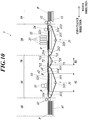
- the ventilation member 323 may be provided all over the upper side of the housing 321 in the support suction unit 32 of the fixing unit 30 as shown in Fig. 10 .
- the ventilation member 323 may be provided all over the upper side of the housing 321 in the support suction unit 32 of the fixing unit 30 as shown in Fig. 10 .
- the sheet member conveyance apparatus includes:
- the air chamber 322 comprises:
- the ventilation member 323 is provided such that, when the suction fan 62 sucks air from the air chamber 322, pressure loss in the ventilation path from the mounting surface side of the conveyance belt 311 to the first section R1 is smaller than pressure loss from the mounting surface side of the conveyance belt 311 to the second section R2.
- the recording medium P is strongly pressed against the mounting surface by the difference in the atmospheric pressure, and the recording medium P is adsorbed on the mounting surface with a higher adsorption sustainability.
- an edge of the recording medium P is reliably drawn and adsorbed to the mounting surface in the first section R1 while, in the second section R2 which is downstream from the first section R1 in the conveyance direction, the recording medium P is adsorbed and kept on the mounting surface with a high adsorption sustainability.
- the ventilation member 323 is provided in a range overlapping with the second section R2 as seen in the direction perpendicular to the mounting surface.
- the first section R1 in the air chamber 322 is ventilated along a ventilation path that does not pass through the ventilation member 323. Therefore, pressure loss by the ventilation member 323 does not occur in the first section R1. Pressure loss in the first section R1 is suppressed, and power to draw the recording medium P to the mounting surface is increased.
- the ventilation member 323 of Modifications 1 and 2 ( Fig. 6B and Fig. 6C ) is provided in a range overlapping with the first section R1 and the second section R2 as seen in the direction perpendicular to the mounting surface.
- the first section R1 in the air chamber 322 is ventilated along a ventilation path through the ventilation member 323. Therefore, the ventilation member 323 supports the conveyance belt 311 over the entire air chamber 322. Accordingly, the mounting surface of the conveyance belt 311 and the recording medium P on the mounting surface are kept flat in a wider range.
- each of portions of the ventilation member 323 overlapping with the first section R1 and the second section R2 has a flat plate shape.
- the thickness of the portion overlapping with the first section R1 in the direction perpendicular to the mounting surface is smaller than the thickness of the portion overlapping with the second section R2 in the direction perpendicular to the mounting surface. Therefore, it is easy to make pressure loss in the ventilation path in the first section R1 smaller than pressure loss in the ventilation path in the second section R2.
- the drawing power for the recording medium P in the first section R1 and the adsorption sustainability in the second section R2 are increased.
- the ventilation member 323 is constituted by the porous body, it is possible to realize the ventilation member 323 having ventilation while supporting the conveyance belt 311 with a simple configuration. Since the entire surface of the ventilation member 323 has ventilation, constant ventilation between the air chamber 322 and the mounting surface side of the conveyance belt 311 is performed regardless of positions of the vents 311a corresponding to conveyance of the conveyance belt 311.
- the open ratio of pores in a cross section parallel to the mounting surface in the portion overlapping with the first section R1 is larger than the open ratio of pores in the cross section parallel to the mounting surface in the portion overlapping with the second section R2. Therefore, it is possible to make pressure loss in the ventilation path in the first section R1 smaller than pressure loss in the ventilation path in the second section R2. Thus the drawing power for the recording medium P in the first section R1 and the adsorption sustainability in the second section R2 are increased.
- the ventilation member 323 of Modification 2 is constituted by a plate provided with through holes 323a (323b) penetrating in the direction perpendicular to the mounting surface.
- the ventilation member 323 having ventilation while supporting the conveyance belt 311 with a simple configuration.
- the open ratio of through holes 323a in the cross section parallel to the mounting surface in the portion overlapping with the first section R1 is larger than the open ratio of through holes 323b in the cross section parallel to the mounting surface in the portion overlapping with the second section R2. Therefore, it is possible to make pressure loss in the ventilation path in the first section R1 smaller than pressure loss in the ventilation path in the second section R2. Thus the drawing power for the recording medium P in the first section R1 and the adsorption sustainability in the second section R2 are increased.
- the air chamber 322 consists of the first section R1 within the predetermined range from the edge of the air chamber 322 on the upstream side in the conveyance direction, and the second section R2 which is the region other than the first section R1. Therefore, the adsorption state of the recording medium P drawn to the mounting surface in the first section R1 near the edge of the air chamber 322 on the upstream side in the conveyance direction is reliably kept in the second section R2 which extends to the downstream edge of the air chamber 322.
- the air chamber 322 of Modification 3 includes a first sub chamber 3221 that constitutes the first section R1 and a second sub chamber 3222 that constitutes the second section R2. Ventilation is not directly performed between the first sub chamber 3221 and the second sub chamber 3222.
- the suction fan 62 sucks air through the first sub chamber 3221 and the second sub chamber 3222 respectively. Therefore, the negative pressure in the second section R2 is easily increased, and thus the absorption sustainability in the second section R2 is increased.
- the suction fan 62 of Modification 3 includes the first suction fan that sucks air through the first sub chamber 3221, and the second suction fan that sucks air through the second sub chamber 3222. Therefore, it is possible to separately adjust the drawing power in the first section R1 and the adsorption sustainability in the second section R2.
- the conveyance belt 311 is a circular conveyance belt, and the external circumference of the circular conveyance belt constitutes the mounting surface.
- the medium conveyer 31 moves the conveyance belt 311 along a predetermined circuit path.
- the ventilation member 323 and the air chamber 322 are provided on the internal circumference side of the conveyance belt 311. Therefore, the recording medium P is more reliably adsorbed on the external circumference of the conveyance belt 311 in the medium conveyer 31 that has a simple and compact configuration for rotating the conveyance belt 311.
- the sheet member conveyance apparatus of Modification 5 includes:
- the medium conveyers 71, 31 move the conveyance belt 711 and the conveyance belt 311 along respective predetermined circuit paths to convey the recording medium P in the conveyance direction while passing the recording medium P between the conveyance belt 711 and the conveyance belt 311.
- the ventilation member 323 is provided on the internal circumference side of the conveyance belt 311.
- the air chamber 322 is partitioned into:
- the edge is drawn and adsorbed to the mounting surface of the conveyance belt 711 on the upstream side.
- the recording medium P is passed to the conveyance belt 311 on the downstream side while the edge is pressed to suppress warping. Therefore, the recording medium P is reliably adsorbed also on the conveyance belt 311.
- the medium conveyer 71 rotates at least one of the first conveyance rollers, around which the conveyance belt 711 is stretched, to move the conveyance belt 711.
- the medium conveyer 31 rotates at least one of the second conveyance rollers, around which the conveyance belt 311 is stretched, to move the conveyance belt 311.
- the diameter of the drive roller 712 closest to the rear edge e1 of the conveyance path of the recording medium P on the conveyance belt 711 is smaller than the diameter of the driven roller 313 closest to the front edge e2 of the conveyance path of the recording medium P on the conveyance belt 311 among the second conveyance rollers. Therefore, a section where the recording medium P is not adsorbed is shortened.
- the recording medium P is more reliably adsorbed on the mounting surface of the conveyance belt 311 on the downstream side.
- the ink jet recording apparatus 1 in the above embodiment and modifications includes:
- the print head 23 discharges ink, which cures in response to the application of ultraviolet rays, from the nozzle.
- the ink jet recording apparatus 1 includes the ultraviolet irradiator 33 which is provided on the side opposite to the second section R2 of the air chamber 322 across the conveyance belt 311 and which irradiates ink, which has landed on the recording medium P adsorbed on the mounting surface, with ultraviolet rays.
- the ink before ink cures and be fixed, the ink is applied to the surface of the recording medium P placed on the mounting surface of the conveyance belt 311.
- the recording medium P is drawn and adsorbed to the mounting surface by suction of air from the air chamber 322 in the first section R1. This prevents a problem that ink on the recording medium P touches other member to disturb an image.
- the conveyer of the sheet member conveyance apparatus includes:
- the medium conveyer 21 and the medium conveyer 31 move the recording medium P in the conveyance direction while passing the recording medium P between the medium conveyer 21 and the medium conveyer 31.
- the print head 23 discharges ink from the nozzle to the recording medium P being conveyed by the medium conveyer 21.
- the recording medium P on which ink has been discharged by the print head 23, is passed between the medium conveyer 21 and the medium conveyer 31, and the medium conveyer 31 conveys the recording medium P without contaminating the surface of the recording medium P.
- pressure loss in the ventilation path changes at two stages in the first section R1 and the second section R2.
- the material, shape and arrangement of the ventilation member 323 may be determined such that pressure loss gradually increases toward the downstream side in the conveyance direction.
- a section where pressure loss is at an intermediate value between pressure losses in the first section R1 and the second section R2 may be provided between the first section R1 and the second section R2.
- the air chamber 322 consists of the single first section R1 and the single second section R2
- the invention may have any configuration as long as at least one first section R1 and at least one second section R2 downstream from the first section R1 in the conveyance direction are provided.
- the air chamber 322 may have one first section R1 and two second sections R2 disposed on both sides of the first section R1 in the conveyance direction.
- a porous body and a metal plate are used for the ventilation member 323.
- any material may be used as long as pressure loss occurs in the ventilation path in the ventilation member 323 when air is sucked through the ventilation member 323.
- a strip-shaped conveyance belt is given as an example of the conveyance member.
- the invention is not limited thereto.
- the present invention may be applied to a conveyer that conveys a recording medium P by rotation of a cylindrical conveyance drum as the conveyance member.
- the support suction unit (the air chamber and the ventilation member) fixed to the rotation shaft is provided along a curved surface (internal circumference) inside the external circumference of the conveyance drum.
- the rotating drum is provided with vents.
- the support suction unit sucks air to adsorb the recording medium P on the drum surface.
- a mounting member may reciprocate in the conveyance direction in a movement range including a region above the support suction unit.
- ultraviolet curable ink is given as an example of ink discharged from the nozzle of the print head 23.
- the invention is not limited thereto.
- Various materials that polymerize and cure when certain energy is given may be used as ink.
- a thermosetting material that polymerizes when heated an electron beam curable material that polymerizes when irradiated with an electron beam, and the like may be used.
- the ink jet recording apparatus 1 of a single pass system is given as an example.
- the present invention may be applied to an ink jet recording apparatus that records an image while scanning with a print head or a recording head.
- the present invention can be utilized in a sheet member conveyance apparatus and an ink jet recording apparatus.
Landscapes
- Ink Jet (AREA)
- Handling Of Sheets (AREA)
- Delivering By Means Of Belts And Rollers (AREA)
Abstract
Description
- The present invention relates to a sheet member conveyance apparatus and an ink jet recording apparatus.
- There have been ink jet recording apparatuses for discharging ink to a sheet member, such as paper or a resin sheet, to form an image on the sheet member.
- For an ink jet recording apparatus, a sheet member conveyance apparatus for conveying a sheet member by placing the sheet member on a mounting surface of a conveyance member that moves along a predetermined movement path (e.g., a conveyance belt that moves around a predetermined circuit path) is commonly used.
- For such a sheet member conveyance apparatus, there is a technique of fixing a sheet member by adsorbing the sheet member on a mounting surface of a conveyance member by sucking air from the side opposite to the mounting surface through vents provided in the conveyance member. Furthermore, a technique of adsorbing a sheet member on a mounting surface of a conveyance member while ensuring flatness of the sheet member on the mounting surface as well as flatness of the mounting surface by supporting the side opposite to the mounting surface with a flat plate-shaped vent member (e.g., porous body) is known (e.g.,
Patent Document 1 and Patent Document 2). According to such a technique, it is possible to accurately perform various processes for sheet members, such as ink discharge, to form a high-quality image. -
- Patent Document 1:
JP 2013-212922 A - Patent Document 2:
JP 2015-047798 A - However, pressure loss occurs in the vent member while air is sucked through the vent member. Therefore, in order to reliably adsorb the sheet member on the mounting surface when an edge of the sheet member warps and floats on the mounting surface, suction force must be large enough to compensate pressure loss. There is a problem that the apparatus is very large or power consumption is increased.
- An object of the present invention is to provide a sheet member conveyance apparatus and an ink jet recording apparatus capable of more reliably adsorbing a sheet member on a mounting surface.
- To achieve the object, a sheet member conveyance apparatus according to
claim 1 includes: - a conveyer which moves a conveyance member in a conveyance direction to convey a sheet member placed on a mounting surface of the conveyance member;
- a ventilation member which is provided on a side opposite to the mounting surface of the conveyance member along a movement path in the conveyance direction of the conveyance member, and which ventilates in a direction perpendicular to the mounting surface;
- an air chamber which is provided on the side opposite to the mounting surface of the conveyance member along the movement path in a range including a region overlapping with the ventilation member as seen in the direction perpendicular to the mounting surface, so that ventilation between the air chamber and a mounting surface side of the conveyance member is maintained through vents provided in the conveyance member; and
- a suction unit which sucks air from the side opposite to the mounting surface of the conveyance member through the air chamber to adsorb the recording medium P on the mounting surface of the conveyance member,
wherein - the air chamber comprises:
- a first section within a predetermined range in the conveyance direction; and
- a second section which is provided downstream from the first section in the conveyance direction, and which is ventilated along a ventilation path through the vents and the ventilation member, and
- the ventilation member is provided such that, when the suction unit sucks air from the air chamber, pressure loss in a ventilation path from the mounting surface side of the conveyance member to the first section is smaller than pressure loss in a ventilation path from the mounting surface side of the conveyance member to the second section.
- The invention according to claim 2 is the sheet member conveyance apparatus according to
claim 1, wherein
the ventilation member is provided in a range overlapping with the second section as seen in the direction perpendicular to the mounting surface, and
the first section is ventilated along a ventilation path that does not pass through the ventilation member. - The invention according to claim 3 is the sheet member conveyance apparatus according to
claim 1, wherein - the ventilation member is provided in a range overlapping with the first section and the second section as seen in the direction perpendicular to the mounting surface, and
- the first section is ventilated along a ventilation path through the ventilation member.
- The invention according to claim 4 is the sheet member conveyance apparatus according to claim 3, wherein
- each of a portion of the ventilation member overlapping with the first section and a portion of the ventilation member overlapping with the second section as seen in the direction perpendicular to the mounting surface has a flat plate shape, and
- a thickness of the portion overlapping with the first section in the direction perpendicular to the mounting surface is smaller than a thickness of the portion overlapping with the second section in the direction perpendicular to the mounting surface.
- The invention according to claim 5 is the sheet member conveyance apparatus according to any one of
claims 1 to 4, wherein the ventilation member is constituted by a porous body. - The invention according to claim 6 is the sheet member conveyance apparatus according to claim 3 or 4, wherein
- the ventilation member is constituted by a porous body having pores, and
- an open ratio of the pores in a cross section parallel to the mounting surface in the portion overlapping with the first section as seen in the direction perpendicular to the mounting surface is larger than an open ratio of the pores in the cross section parallel to the mounting surface in the portion overlapping with the second section as seen in the direction perpendicular to the mounting surface.
- The invention according to claim 7 is the sheet member conveyance apparatus according to any one of
claims 1 to 4, wherein the ventilation member is constituted by a plate provided with through holes penetrating in the direction perpendicular to the mounting surface. - The invention according to claim 8 is the sheet member conveyance apparatus according to claim 3 or 4, wherein
- the ventilation member is constituted by a plate provided with through holes penetrating in the direction perpendicular to the mounting surface, and
- an open ratio of the through holes in a cross section parallel to the mounting surface in the portion overlapping with the first section as seen in the direction perpendicular to the mounting surface is larger than an open ratio of the through holes in the cross section parallel to the mounting surface in the portion overlapping with the second section as seen in the direction perpendicular to the mounting surface.
- The invention according to claim 9 is the sheet member conveyance apparatus according to any one of
claims 1 to 8, wherein - the first section of the air chamber occupies a predetermined range from an edge of the air chamber on an upstream side in the conveyance direction, and
- the second section is a section other than the first section.
- The invention according to
claim 10 is the sheet member conveyance apparatus according to claim 9, wherein - the air chamber comprises:
- a first sub chamber that constitutes the first section; and
- a second sub chamber that constitutes the second section,
- ventilation is not directly maintained between the first sub chamber and the second sub chamber, and
- the suction unit sucks air through the first sub chamber and the second sub chamber respectively.
- The invention according to
claim 11 is the sheet member conveyance apparatus according toclaim 10, wherein the suction unit comprises: - a first suction fan that sucks air through the first sub chamber; and
- a second suction fan that sucks air through the second sub chamber.
- The invention according to
claim 12 is the sheet member conveyance apparatus according to any one ofclaims 1 to 11, wherein - the conveyance member is a circular conveyance belt,
- an external circumference of the conveyance belt constitutes the mounting surface,
- the conveyer moves the conveyance belt along a predetermined circuit path, and
- the ventilation member and the air chamber are provided on an internal circumference side of the conveyance belt.
- The invention according to claim 13 is the sheet member conveyance apparatus according to any one of
claims 1 to 9, wherein - the conveyance member comprises:
- a first conveyance belt which is circular and which has an external circumference that constitutes the mounting surface; and
- a second conveyance belt which is circular, which is provided downstream from the first conveyance belt, and which has an external circumference that constitutes the mounting surface,
- the conveyer moves the first conveyance belt and the second conveyance belt respectively along predetermined circuit paths to convey the sheet member in the conveyance direction while passing the sheet member between the first conveyance belt and the second conveyance belt,
- the ventilation member is provided on the internal circumference side of the second conveyance belt, and
- the air chamber is partitioned into:
- an upstream chamber which is provided on the internal circumference side of the first conveyance belt and which includes at least a part of the first section; and
- a downstream chamber which is provided on the internal circumference side of the second conveyance belt and which includes the second section.
- The invention according to claim 14 is the sheet member conveyance apparatus according to claim 13, wherein
- the conveyer moves the first conveyance belt by rotating at least one of first conveyance rollers around which the first conveyance belt is stretched,
- the conveyer moves the second conveyance belt by rotating at least one of second conveyance rollers around which the second conveyance belt is stretched, and
- among the first conveyance rollers, a diameter of a first drive roller closest to a rear edge of a conveyance path of the sheet member on the first conveyance belt is smaller than a diameter of a second conveyance roller closest to a front edge of a conveyance path of the sheet member on the second conveyance belt among the second conveyance rollers.
- The invention according to claim 15 is an ink jet recording apparatus, comprising:
- an ink discharger that discharges ink from a nozzle to the sheet member; and
- the sheet member conveyance apparatus according to any one of
claims 1 to 14 that conveys the sheet member on which ink discharged from the nozzle of the ink discharger has landed. - The invention according to claim 16 is the ink jet recording apparatus according to claim 15, wherein
- the ink discharger discharges ink that cures in response to provision of predetermined energy from the nozzle,
- the ink jet recording apparatus comprises an energy applier which is provided on a side opposite to the second section of the air chamber across the conveyance member, and which gives the predetermined energy to ink that has landed on the sheet member adsorbed on the mounting surface.
- The invention according to claim 17 is the ink jet recording apparatus according to claim 15 or 16, wherein
- the conveyer comprises:
- a first conveyer that is provided with the ventilation member so that the vents constitutes ventilation paths to the first section and to the second section; and
- a second conveyer that conveys the sheet member in the conveyance direction upstream from the first conveyer in the conveyance direction,
- the conveyer moves the sheet member in the conveyance direction while passing the sheet member between the first conveyer and the second conveyer, and
- the ink discharger discharges ink from the nozzle to the sheet member being conveyed by the second conveyer.
- According to the present invention, there is an effect that it is possible to more reliably adsorb a sheet member on a mounting surface.
-
-
Fig. 1 is a diagram illustrating a schematic configuration of an ink jet recording apparatus. -
Fig. 2 is a block diagram illustrating a main functional configuration of the ink jet recording apparatus. -
Fig. 3A is a plan view of a support suction unit as seen from an ultraviolet irradiator side. -
Fig. 3B is a cross-sectional view in A-A line ofFig. 3A . -
Fig. 4 is a diagram illustrating suction characteristics of direct suction and suction through a vent member. -
Fig. 5A is a cross-sectional view showing a configuration of a support suction unit according toModification 1. -
Fig. 5B is a cross-sectional view showing a configuration of a support suction unit according toModification 1. -
Fig. 6A is a cross-sectional view showing a configuration of a support suction unit according to Modification 2. -
Fig. 6B is a cross-sectional view showing a configuration of a support suction unit according to Modification 2. -
Fig. 6C is a cross-sectional view showing a configuration of a support suction unit according to Modification 2. -
Fig. 7 is a cross-sectional view showing a configuration of a support suction unit according to Modification 3. -
Fig. 8 is a plan view showing a configuration of a support suction unit according to Modification 4. -
Fig. 9 is a diagram illustrating a schematic configuration of an ink jet recording apparatus according to Modification 5. -
Fig. 10 is a diagram illustrating a schematic configuration of an ink jet recording apparatus according to Modification 5. - Hereinafter, embodiments of the sheet member conveyance apparatus and the ink jet recording apparatus of the present invention will be described with reference to the drawings.
-
Fig. 1 is a diagram illustrating a schematic configuration of an inkjet recording apparatus 1 according to an embodiment of the present invention. - The ink
jet recording apparatus 1 includes arecording medium supplier 10, animage recorder 20, a fixingunit 30, arecording medium ejector 40, and the like. - The
recording medium supplier 10 includes a mountingtray 11,medium carrier rollers 12 and the like. - The mounting
tray 11 is a plate-shaped member on which various kinds of recording medium P (sheet member), such as paper, cardboard, corrugated cardboard and a resin sheet, are piled up. The uppermost recording medium P on the mounting tray is sent to theimage recorder 20 one by one. The mountingtray 11 is movable in the vertical direction. In accordance with, for example, the total weight of the placed recording media P, the uppermost recording medium P is kept at a position for sending the recording medium P to theimage recorder 20. -
Medium carrier rollers 12 are rotatable rollers that sandwich the recording medium P from above and below, and send the uppermost recording medium P mounted on the mountingtray 11. In this embodiment, the recording medium P is sent in a horizontal direction. A guide member for aligning the recording medium P to a predetermined position in a width direction perpendicular to the conveyance direction of the recording medium P (leftward inFig. 1 ) is attached to themedium carrier rollers 12. Themedium carrier rollers 12 send the recording medium P aligned in the width direction to theimage recorder 20. - The
image recorder 20 discharges ink onto the recording medium P passed from therecording medium supplier 10 to form an image. After ink lands on the recording medium P to form an image, the recording medium P is sent to the fixingunit 30. Theimage recorder 20 comprises a medium conveyer 21 (second conveyer), asupport suction unit 22, one or more (in this embodiment, four) print heads 23 that discharge ink (ink discharger), apress roller 24, and the like. Themedium conveyer 21 comprises aconveyance belt 211, adrive roller 212, a drivenroller 213, guiderollers 214, and atension roller 215. - The
conveyance belt 211 of the medium conveyer 21 (conveyance member) is an endless (circular) strip member. A steel belt is used in this embodiment. The steel belt is made of, for example, stainless steel such as SUS304 and SUS631 or aluminum alloy having thickness of about 0.3 mm Theconveyance belt 211 is provided with vents which have the same opening shape and which penetrate between the external circumference and the internal circumference of theconveyance belt 211. Specifically, a large number (plurality) of circular vents having a diameter of about 0.5 mm are arranged at about 1.4 mm intervals so that the open ratio is about 20%. Air passes between the external circumference and the internal circumference. - The
conveyance belt 211 bridges between thedrive roller 212 and the driven roller 213 (hereinafter, these rollers together are also referred to asconveyance rollers 212, 213). The external circumference on which the recording medium P is mounted (hereinafter, also referred to as a mounting surface) is movable along a circuit path around theconveyance rollers drive roller 212 rotates in accordance with rotation driven by a conveyance motor 65 (Fig. 2 ), theconveyance belt 211 moves along the circuit path around theconveyance rollers drive roller 212. In this embodiment, thedrive roller 212 rotates counterclockwise on the plane ofFig. 1 so that theconveyance belt 211 rotates counterclockwise. Thereby a portion of theconveyance belt 211 corresponding to the conveyance section from the drivenroller 213 to thedrive roller 212 moves in the conveyance direction. The recording medium P placed on the mounting surface of theconveyance belt 211 in the conveyance section is conveyed along the movement path in the conveyance direction of theconveyance belt 311 as theconveyance belt 311 moves. - A flat surface (in this embodiment, a horizontal surface) of the support suction unit 22 (hereinafter referred to as a support surface) supports the internal circumference of the conveyance belt 211 (the surface that touches the
conveyance rollers 212, 213) in a range within the conveyance section of theconveyance belt 211, the range including a portion where the mounting surface of theconveyance belt 211 faces an ink discharge surface of the print heads 23. The support surface of thesupport suction unit 22 consists of a plate-shapedvent member 223 constituted by a porous body having ventilation. Thesupport suction unit 22 has a suction fan 62 (Fig. 2 ) (suction unit) that sucks air from the internal circumference side of theconveyance belt 211 through the vents of theconveyance belt 211 and thevent member 223. Thus the recording medium P, which is placed on the mounting surface of theconveyance belt 211, is adsorbed on the mounting surface. -
Guide rollers 214 are provided respectively upstream and downstream from thesupport suction unit 22 in the conveyance direction. Twoguide rollers 214 support the internal circumference of theconveyance belt 211 outside both edges of the support surface of thesupport suction unit 22. Theguide rollers 214 respectively support theconveyance belt 211 at substantially the same height as the support surface of thesupport suction unit 22 to guide circumferential movement of theconveyance belt 211. - The
press roller 24 is rotatably provided at a position opposed to theupstream guide roller 214 across theconveyance belt 211. Upstream in the conveyance direction from a position on the recording medium P where ink is discharged, thepress roller 24 presses down the recording medium P on theconveyance belt 211 at an appropriate pressure and guide the recording medium P along theconveyance belt 211. Thereby the recording medium P, which has been sent from therecording medium supplier 10, is prevented from separating from theconveyance belt 211. Especially, an edge of the recording medium P is prevented from warping (curling) so that the recording medium P is more reliably adsorbed. Thepress roller 24 may be configured such that the distance from the conveyance surface of theconveyance belt 211 is variable in accordance with the thickness or the like of the recording medium P to be conveyed. - In order to give appropriate tension, on the side where the external circumference of the
conveyance belt 211 is not opposed to the print heads 23, thetension roller 215 presses theconveyance belt 211 from the internal circumference side at a position between the twoconveyance rollers conveyance belt 211 from thedrive roller 212 to the drivenroller 213. The vertical position of thetension roller 215 is adjustable at two different positions in the width direction, for example, at both edges. Thetension roller 215 corrects meander caused by non-uniformity of tension on theconveyance belt 211 applied by thesupport suction section 22 and the like. Thereby theconveyance belt 211 and the recording medium P are properly moved in the conveyance direction. - The print heads 23 are provided on the side opposite to the
support suction unit 22 across theconveyance belt 211. On the side facing theconveyance belt 211, the print heads 23 have an ink discharge surface provided with nozzle openings. The print heads 23 discharge ink to the recording medium P which is transferred while being adsorbed on the mounting surface of theconveyance belt 211 by thesupport suction unit 22. Thus ink lands on the recording medium P. The print heads 23 have one or more recording heads 231 (Fig. 2 ) in which nozzle openings are provided in a predetermined arrangement to perform an operation relating to ink discharge from the nozzle openings. A range in the width direction in which an image is formed on the recording medium P is within a range in the width direction in which the nozzles of the print heads 23 are arranged. The positions of the print heads 23 are fixed while an image is recorded. Ink is discharged sequentially on different positions in the conveyance direction at predetermined intervals (intervals in the conveyance direction) as the recording medium P is conveyed. Thereby an image is formed in a single-pass manner. The fourprint heads 23 are respectively connected to ink tanks (not shown) of colors cyan (C), magenta (M), yellow (Y) and black (K) to respectively discharge ink of these CMYK colors. Alternatively, theimage recorder 20 may include aprint head 23 for discharging ink other than these four colors, such as orange, green, violet, red, blue, white, or the like, or transparent ink. - Ink that changes phase between gel and sol is used as ink discharged from the nozzles of the print heads 23. Gel is classified as solid while Sol is classified as liquid. In the present embodiment, ink that has been made gelatinous through heating is discharged from the nozzles of the print heads 23. After ink lands on the recording medium P, the ink is cooled down to be gelatinous rapidly, and solidifies on the recording medium P.
- In the present embodiment, ink that cures under ultraviolet rays (curable material) is used. Ink that contains a photopolymerizable compound (monomer), a photopolymerization initiator and a colorant are used as this kind of ink. Among them, photopolymerizable compound polymerizes through polymerization reaction under ultraviolet rays. Ink cures through the polymerization. The photopolymerization initiator is a compound that initiates the above polymerization reaction. The colorant includes a pigment or dye of an ink color.
- The
image recorder 20 sends the recording medium P, on which ink has been discharged from theprint head 23, to the fixingunit 30. - The fixing
unit 30 is provided downstream from theimage recorder 20 in the conveyance direction of the recording medium P, and fixes ink on the recording medium P passed from theimage recorder 20. The fixingunit 30 includes a medium conveyer 31 (first conveyer), asupport suction unit 32, an ultraviolet irradiator 33 (energy provider), and the like. Themedium conveyer 31 has aconveyance belt 311, adrive roller 312, a drivenroller 313, aguide roller 314, and atension roller 315. - The configuration of the
medium conveyer 31 is the same as that of themedium conveyer 21 of theimage recorder 20. - The configuration of the
support suction unit 32 is different from thesupport suction unit 22 of theimage recorder 20 in that theventilation member 323 of the porous body, which constitutes the support surface, is provided in a region excluding a predetermined range in the edge of thesupport suction unit 32 on the upstream side in the conveyance direction. As described later, according to thesupport suction unit 32 having this configuration, the recording medium P is reliably adsorbed on the mounting surface of theconveyance belt 211 even if the recording medium P includes a warp or the like. Therefore, the fixingunit 30 is not provided with a press roller. The configuration of thesupport suction unit 32 will be described in detail later. - In an irradiation range in the width direction of the conveying
belt 311, theultraviolet irradiator 33 irradiates the recording medium P with ultraviolet rays, the recording medium P being conveyed while being adsorbed on the mounting surface of the conveyingbelt 311 by thesupport suction unit 32. Accordingly, ink on the recording medium P (ink that has landed on the recording medium P) cures to be fixed. Preferably, the recording medium P mounted on theconveyance belt 311 is irradiated with ultraviolet rays from theultraviolet irradiator 33 without large unevenness (variation in intensity). - The fixing
unit 30 sends the recording medium P, on which ink has been fixed, to therecording medium ejector 40. - The recording medium P passed from the fixing
unit 30 is held on therecording medium ejector 40 until it is taken out by the user. Therecording medium ejector 40 includes anejection tray 41 and guiderollers 42. Theguide rollers 42 sandwich the recording medium P, which has been sent from the fixingunit 30, from above and below, conveys the recording medium P, and put it on theejection tray 41. In order to carry the recording medium P from the mounting surface of theconveyance belt 311, theejection tray 41 may be set at a position lower than the mounting surface and be vertically movable in accordance with the amount of the mounted recording medium P. - As described above, the ink
jet recording apparatus 1 has a configuration that, while the recording medium P is conveyed by themedium conveyers jet recording apparatus 1 including the medium conveyingportions image recorder 20 and the fixingunit 30. This configuration shortens the ranges in which the recording medium P is placed on theconveyance belts medium conveyers conveyance belts image recorder 20 discharges ink to a desired position on the recording medium P. Further, it is possible to avoid problem that heat generated by the ultraviolet irradiation in the fixingunit 30 is transmitted to the recording medium P in theimage recorder 20 so that the temperature of the recording medium P deviates from a proper range for discharging ink. - The configuration of the ink
jet recording apparatus 1 is not limited to those described above. For example, a heater that heats the recording medium P to a predetermined temperature, a medium processor for performing a surface modification process, such as corona treatment, for the recording medium P, and the like may be provided between therecording medium supplier 10 and theimage recorder 20. -
Fig. 2 is a block diagram illustrating the main functional configuration of the inkjet recording apparatus 1. - The ink
jet recording apparatus 1 includes acontroller 50,support suction units suction controller 61 and asuction fan 62, aprint head 23 having ahead controller 63 and arecording head 231, aconveyance controller 64, aconveyance motor 65, an input-output interface 66, abus 67, and the like. A hardware configuration of thecontroller 50 may also be used as thesuction controller 61, thehead controller 63, or theconveyance controller 64. Alternatively, a dedicated CPU, a memory, a logic circuit, or the like may be provided separately. - The
controller 50 includes a CPU 51 (Central Processing Unit), a RAM 52 (Random Access Memory), a ROM 53 (Read Only Memory), and amemory 54. - The
CPU 51 reads the program and setting data stored in theROM 53 for various control, stores them in theRAM 52, and execute the program to perform various arithmetic processes. In addition, theCPU 51 oversees and controls the entire operation of the inkjet recording apparatus 1. - The
RAM 52 provides theCPU 51 with a memory space for working and stores temporary data. TheRAM 52 may include a non-volatile memory. - The
ROM 53 stores various control programs and setting data executed by theCPU 51. A rewritable non-volatile memory such as an EEPROM (Electrically Erasable Programmable Read Only Memory) or a flash memory may be used instead of theROM 53. - The
memory 54 stores a print job (image recording instruction) input from the external device 2 through the input-output interface 66 and image data of an image to be recorded by the print job. As thememory 54, for example, a HDD (Hard Disk Drive) is used. A DRAM (Dynamic Random Access Memory) or the like may be used together. -
Suction controller 61 rotates thesuction fan 62 of thesupport suction unit controller 50. - The
head controller 63 outputs various control signals and image data to a head driver in therecording head 231 at appropriate time in accordance with a control signal from thecontroller 50. Thereby ink is discharged from the nozzle opening of therecording head 231. - The
conveyance controller 64, based on a control signal supplied from thecontroller 50, controls operation of theconveyance motors 65 respectively connected to themedium carrier roller 12 and thedrive rollers - The input-
output interface 66 mediates transmission and reception of data between the external device 2 and thecontroller 50. The input-output interface 66 may comprise, for example, one of various serial interfaces or various parallel interfaces, or a combination thereof. - The
bus 67 is a path for transmitting and receiving signals between thecontroller 50 and other configurations. - The external device 2 is, for example, a personal computer, and supplies print jobs, image data, etc. to the
controller 50 via the input-output interface 66. - Among the components of the ink
jet recording apparatus 1 described above, themedium conveyers support suction units conveyance controller 64, and theconveyance motors 65 constitute the sheet member conveyance apparatus. Themedium conveyers medium conveyer 31 alone constitutes the conveyer. - Next, detailed configurations and operations of the
support suction unit 32 of the fixingunit 30 will be described. -
Fig. 3A is a plan view of thesupport suction unit 32 as seen from theultraviolet irradiator 33 side. InFig. 3A , for facilitation of understanding, each configuration is shown through theconveyance belt 311, and vents provided in theconveyance belt 311 are omitted. -
Fig. 3B is a cross-sectional view in line A-A ofFig. 3A . -
Support suction unit 32 includes acuboid housing 321, aventilation member 323, asuction fan 62, and the like. Thecuboid housing 321 is opened on the side of theconveyance belt 311. Theventilation member 323 consists of a plate-shaped porous body that partially closes the open side of thehousing 321. Thesuction fan 62 sucks air from thehousing 321. The open side of thehousing 321 is covered with theconveyance belt 311. Thereby, anair chamber 322 is formed inside thehousing 321. Thesuction fan 62 sucks air from theair chamber 322 through asuction port 321a opened in a part of the lower portion of thehousing 321. - The
housing 321 is made of a metal plate such as stainless steel or aluminum alloy having a thickness of some millimeters. The lengths of thehousing 321 in the width direction and in the conveyance direction are appropriately determined in accordance with the size, shape, and the like of the recording medium P to be conveyed by themedium conveyer 31. According to the embodiment ofFig. 3 , thesuction port 321a is provided in the vicinity of the edge of the bottom surface of thehousing 321 on the upstream side in the conveyance direction. However, the position of thesuction port 321a is not limited thereto. - The
ventilation member 323 is a plate-shaped porous body having a thickness of about 5 mm fixed to thehousing 321 along the open side of the housing 321 (i.e., along the movement path of the conveyance belt 311). Theventilation member 323, as seen in a direction perpendicular to the mounting surface of theconveyance belt 311, is provided in a range overlapping a second section R2 which corresponds to a range of theair chamber 322 excluding a first section R1 in a predetermined range at the edge on the upstream side in the conveyance direction. Therefore, in the first section R1, theair chamber 322 is not provided with theventilation member 323, and the upper side of thehousing 321 is opened. - Since the
ventilation member 323 is disposed in this way, in the first section R1, ventilation between theair chamber 322 and the mounting surface side of theconveyance belt 311 is maintained along a ventilation path that passes not through theventilation member 323 but through thevents 311a of theconveyance belt 311. In the second section R2, ventilation between theair chamber 322 and the mounting surface side of theconveyance belt 311 is maintained along a ventilation path through thevents 311a of theconveyance belt 311 and through theventilation member 323. - The length of the first section R1 in the
air chamber 322 in the conveyance direction is not particularly limited as long as it is set to be longer than a length in which an edge Pc of the recording medium P could warp. This is for sufficiently achieving effect that the warped edge Pc of the recording medium P is adsorbed on the mounting surface, which will be described later. - Preferably, the length of the second section R2 in the
air chamber 322 in the conveyance direction is set at, for example, approximately the length of the recording medium P in the conveyance direction (based on a standard length, the maximum length, or the like among various lengths of the recording medium P to be conveyed).
More preferably, the length of the second section R2 in the conveyance direction is set to be longer than the maximum length of the recording medium P so that the entire recording medium P is adsorbed within the second section R2. Therefore, usually, the length of the second section R2 in the conveyance direction is set at a length longer than the length of the first section R1 in the conveyance direction, and is several times or more than ten times as long as the length of the first section R1 in the conveyance direction. Theultraviolet irradiator 33 is disposed on the side opposite to the second section R2 of theair chamber 322 across the conveyance belt 311 (seeFig. 1 ). - The length of the first section R1 and the second section R2 in the width direction (i.e., the length of the
housing 321 and theventilation member 323 in the width direction) is set at a length equal to or longer than the maximum length in the width direction of the recording medium P to be conveyed. - The porous body constituting the
ventilation member 323 is made by sintering, for example, resin particles such as polyethylene resin, fluororesin, and polypropylene resin. Netlike pores spreading three-dimensionally inside the porous body constitute ventilation paths. This achieves three-dimensional ventilation. - The frictional resistance between the
conveyance belt 311 and theventilation member 323 constituted by the porous body of the above material is low. Therefore, it is possible to avoid damage to theconveyance belt 311, and to reduce a load on theconveyance motor 65. While theconveyance belt 311 slides on theventilation member 323, wear powder is hardly generated since the frictional resistance is low as described above. - The
suction fan 62 sucks air from theair chamber 322 through thesuction port 321a with a suction force controlled by thesuction controller 61, and discharges air. Thus a negative pressure is created in theair chamber 322. - Thus, as shown by a solid arrow in the
air chamber 322 inFig. 3B , air flows vertically downward toward thesuction port 321a through thevents 311a of theconveyance belt 311 in the first section R1. Thus air is discharged out of thehousing 321. Hereinafter, suction of air in the first section R1 not through theventilation member 323 but through thevents 311a is also referred to as "direct suction". - In the second section R2, air flows vertically downward through the
vents 311a of theconveyance belt 311 and through theventilation member 323. Then air flows toward thesuction port 321a in the direction opposite to the conveyance direction in the vicinity of the bottom surface of thehousing 321. Thus air is discharged out of thehousing 321. Hereinafter, suction of air in the second section R2 through thevents 311a and theventilation member 323 is also referred to as "suction through the ventilation member". -
Fig. 4 is a diagram illustrating the suction characteristics of the direct suction and the suction through the ventilation member. - In
Fig. 4 shows the relation between the direct suction and the suction through the ventilation member concerning drawing power and adsorption sustainability. The drawing power is a force for drawing the recording medium P, which is separated from (floating on) the mounting surface of theconveyance belt 311 by a predetermined distance in the vertical direction, to the mounting surface. The adsorption sustainability is a force for keeping an adsorption state by preventing the recording medium P, which is adsorbed on the mounting surface, from separating from the mounting surface or from sliding on the mounting surface. - The "L" in
Fig. 4 indicates that the drawing power or the adsorption sustainability is larger than the "S". As shown inFig. 4 , the drawing power in the direct suction is larger than that in the suction through the ventilation member. The adsorption sustainability in the suction through the ventilation member is larger than that in the direct suction. Reasons will be described below. - Suction of air by the
suction fan 62 causes pressure loss in thevents 311a of theconveyance belt 311 and in theventilation member 323. Pressure loss is caused by loss due to friction between air and walls of an air flow path, contracted flow due to decrease in an area of a flow path, separation of air flow due to increase in an area of a flow path, loss at an inlet and an outlet of a flow path, and the like. - In the
support suction unit 32 of the embodiment, the open area and the open ratio of thevents 311a is large enough with respect to the velocity and viscosity of air. The length (depth) in the vertical direction is sufficiently small. Therefore, pressure loss at thevents 311a is very little. On the other hand, since the fine pores in the porous body of theventilation member 323 constitute air flow paths, pressure loss due to various factors described above is larger than that in thevents 311a. Therefore, pressure loss along the ventilation path through thevents 311a and theventilation member 323 in the suction through the ventilation member in the second section R2 is larger than pressure loss along the ventilation path through thevents 311a in the direct suction in the first section R1 by an amount corresponding to pressure loss in theventilation member 323. - In the first section R1 where pressure loss is small, since air is sucked into the
vent 311a from the mounting surface side of theconveyance belt 311 at a pressure corresponding approximately to the negative pressure in theair chamber 322, the flow rate F1 (Fig. 3B ) of sucked air on the mounting surface is large. Therefore, the drawing power for the recording medium P separated from the mounting surface is large. - On the other hand, in the second section R2 where pressure loss is large, air is sucked into the
vent 311a from the mounting surface side of theconveyance belt 311 by a negative pressure of an absolute value smaller than an absolute value of the negative pressure in theair chamber 322. Therefore, the flow F2 (Fig. 3B ) of air on the mounting surface is smaller than the flow F1. Accordingly, the drawing power for the recording medium P separated from the mounting surface is smaller than that in the first section R1. - Because of this, as shown in
Fig. 4 , the drawing power of the direct suction in the first section R1 is larger than that of the suction through the ventilation member in the second section R2. - In the
support suction unit 32, even after the recording medium P is adsorbed on the mounting surface, the region around the recording medium P as seen from a direction perpendicular to the mounting surface (i.e., both sides of the recording medium P in the width direction as well as the upstream and downstream sides in the conveyance direction), air is sucked into theair chamber 322 from the mounting surface side of theconveyance belt 311. - During this suction, since pressure loss of the air passing through the
vents 311a of theconveyance belt 311 is very little in the first section R1, difference in the atmospheric pressure between theair chamber 322 and the area beside the mounting surface of theconveyance belt 311 hardly occurs. This prevents the effect of the difference in the atmospheric pressure, that is, facilitation of adsorption and maintenance of recording medium P on the mounting surface. Thus the adsorption sustainability decreases. - On the other hand, since pressure loss of air passing through the
vents 311a of theconveyance belt 311 and theventilation member 323 is large in the second section R2, the difference in the atmospheric pressure between theair chamber 322 and the area beside the mounting surface of theconveyance belt 311 is large (the air pressure in theair chamber 322 is relatively small). In other words, theventilation member 323 with large pressure loss seals the upper surface of theair chamber 322 with a certain degree of airtightness. Since the difference in the atmospheric pressure between theair chamber 322 and the mounting surface side of theconveyance belt 311 is large, the recording medium P is strongly pressed against the mounting surface by the difference. Thus the adsorption sustainability to adsorb and keep the recording medium P on the mounting surface increases. - Because of this, as shown in
Fig. 4 , the adsorption sustainability of the suction through the ventilation member in the second section R2 is larger than that of the direct suction in the first section R1. - In the
support suction unit 32 of the embodiment, the first section R1, where the drawing power is large, is provided upstream in the conveyance direction. Therefore, even if the edge Pc on the front side of the recording medium P warps (floats on the mounting surface), it is possible to draw and adsorb the edge Pc on the mounting surface by the direct suction when the recording medium P is conveyed by theconveyance belt 311 to the first section R1. - When the recording medium P adsorbed on the mounting surface is conveyed in the conveyance direction to the second section R2, the recording medium P is adsorbed with a strong adsorption sustainability by the suction through the ventilation member. Therefore, the edge Pc of the recording medium P is prevented from floating on the mounting surface again or sliding on the mounting surface. Thus problems are avoided.
- The
controller 50 controls the rotation speed of thesuction fan 62 such that the rotation speed is equal to or more than the minimum rotation speed that achieves a drawing power large enough to draw and adsorb the warped edge Pc of the recording medium P. The minimum rotation speed varies in accordance with various parameters such as the type (thickness, hardness, ventilation, etc.) of the conveyed recording medium P, the size of an assumed warpage (height from the mounting surface), the width in the width direction of the recording medium P (i.e., the width of the portion of the first section R1 not covered by the recording medium P), and the like. Therefore, the rotational speed of thesuction fan 62 is predetermined in accordance with, for example, each combination of these parameters. Alternatively, an edge Pc of one of recording media P to be used may be made to warp, and then conveyed. The rotation speed is set at a speed in which the edge Pc is actually adsorbed. - On the recording medium P mounted on the mounting surface of the
conveyance belt 311 in the fixingunit 30, ink discharged in theimage recorder 20 has not cured. Therefore, if the surface of the recording medium P with a warped edge Pc is pressed by a press roller, uncured ink on the recording medium P touches the press roller to distort an image, or the press roller is contaminated with ink. It is unfavorable. However, according to the configuration of the embodiment, the recording medium P is adsorbed on the mounting surface and is conveyed to a position facing theultraviolet irradiator 33 without such problems. - In the
support suction unit 22 in theimage recorder 20, theventilation member 223 is provided all over the surface of the housing, and the suction through the ventilation member is performed in the entiresupport suction unit 22. In a case in which the edge Pc of the recording medium P warps, the edge Pc is pressed against the mounting surface by thepress roller 24 as described above, and is adsorbed on the mounting surface. This is because, since ink is not discharged to the recording medium P in theimage recorder 20, the above problems do not happen when thepress roller 24 directly presses the surface of the recording medium P. - Next, conveyance operation of the recording medium P and recording operation of images in the ink
jet recording apparatus 1 according to the embodiment will be described. - In the ink
jet recording apparatus 1, recording operation of an image begins when a print job is stored in thememory 54 of thecontroller 50. - When the recording operation begins, a control signal is output from the
suction controller 61 to eachsuction fan 62 of thesupport suction units suction fan 62 at a predetermined rotational speed begins. - A control signal is output from the
conveyance controller 64 to theconveyance motors 65 respectively connected to themedium carrier rollers 12 and thedrive rollers recording medium supplier 10 to themedium conveyer 21 of theimage recorder 20 and conveyance operation of the recording medium P by themedium conveyers - At an appropriate time in accordance with a position of the recording medium P conveyed by the
medium conveyer 21, thehead controller 63 supplies image data of an image to be recorded and a control signal to eachrecording head 231 of theprint head 23. Thereby ink is discharged from the nozzle of theprint head 23, and an image is recorded on the recording medium P. At the time of recording the image, the recording medium P is adsorbed and fixed on the mounting surface of theconveyance belt 211 with a strong adsorption sustainability by the suction through the ventilation member in thesupport suction unit 22. This prevents erroneous recording caused by floating or vibration of the recording medium P. - The recording medium P on which ink has been discharged is passed from the
medium conveyer 21 of theimage recorder 20 to themedium conveyer 31 of the fixingunit 30. In a case in which the front edge of the recording medium P warps, the recording medium P is effectively drawn and adsorbed on the mounting portion of theconveyance belt 311 by the direct suction in a portion of thesupport suction unit 32 overlapping with the first section R1 as described above. Then, the recording medium P is conveyed to a portion overlapping with the second section R2, and the recording medium P is adsorbed and fixed on the mounting surface of theconveyance belt 211 with a strong adsorption sustainability by the suction through the ventilation member. Theultraviolet irradiator 33 performs curing and fixation of ink on the recording medium P in this state. This prevents erroneous fixation caused by floating or vibration of the recording medium P. - After ink is fixed, the recording medium P is ejected to the
recording medium ejector 40 by conveyance operation of themedium conveyer 31. - Next,
Modification 1 of the above embodiment will be described. This modification and the above embodiment are different in the configuration of thesupport suction unit 32. -
Fig. 5A and Fig. 5B are cross-sectional views showing a configuration of thesupport suction unit 32 according to the modification. - According to the
support suction unit 32 inFig. 5A and Fig. 5B , theventilation member 323 is provided in a range overlapping with theentire air chamber 322 as seen in a direction perpendicular to the mounting surface of theconveyance belt 311. Portions of theventilation member 323 inFig. 5A and Fig. 5B overlapping with the first section R1 and the second section R2 respectively have a flat plate shape. The material, shape and arrangement of theventilation member 323 is determined such that pressure loss in the portion overlapping with the first section R1 is smaller than pressure loss in the portion overlapping with the second section R2. - Specifically, in the example in
Fig. 5A , theventilation member 323 consists of afirst portion 3231 and asecond portion 3232. Thefirst portion 3231 is provided in a range overlapping with the first section R1, and is constituted by a porous body with coarse pores. Thesecond portion 3232 is provided in a range overlapping with the second section R2, and is constituted by a porous body with pores finer than those in thefirst portion 3231. According to theventilation member 323 inFig. 5A , the open ratio of the pores in a cross section parallel to the mounting surface of thefirst portion 3231 is larger than the open ratio of the pores in a cross section parallel to the mounting surface of thesecond portion 3232. In other words, the porosity of the porous body of thefirst portion 3231 is larger than the porosity of the porous body of thesecond portion 3232. According to the configuration inFig. 5A , pressure loss in the portion overlapping with the first section R1 of theventilation member 323 is smaller than pressure loss in the portion overlapping with the second section R2. - In the
ventilation member 323 of the example inFig. 5B , the thickness in the direction perpendicular to the mounting surface in thefirst portion 3233 overlapping with the first section R1 is smaller than the thickness in the direction perpendicular to the mounting surface in thesecond portion 3234 overlapping with the second section R2. The fineness of the porous body (i.e., the open ratio of the pores in a cross section parallel to the mounting surface) in each of thefirst portion 3233 and thesecond portion 3234 is the same as that of the porous body constituting theventilation member 323 of the above embodiment. Also according to the configuration inFig. 5B , pressure loss in the portion of theventilation member 323 overlapping with the first section R1 is smaller than pressure loss in the portion overlapping with the second section R2. - According to the configurations in
Fig. 5A and Fig. 5B , the suction through the ventilation member is performed in both the first section R1 and the second section R2. Pressure loss in the portion overlapping with the first section R1 is smaller than pressure loss in the portion overlapping with the second section R2. Therefore, like the above embodiment, the drawing power is larger in the first section R1 than in the second section R2 while the adsorption sustainability is larger in the second section R2 than in the first section R1. Thus, also according to the configuration of the modification, the front edge of the recording medium P is securely adsorbed in the first section R1 while the recording medium P is adsorbed with a high adsorption sustainability in the second section R2. - The first portion and the second portion of the
ventilation member 323 may be different inboth the fineness and the thickness of the pores. - Next, Modification 2 of the above embodiment will be described. This modification and the above embodiment are different in the configuration of the
support suction unit 32. -
Fig. 6A to Fig. 6C are cross-sectional views showing a configuration of thesupport suction unit 32 according to the modification. - According to the
support suction unit 32 inFig. 6A to Fig. 6C , theventilation member 323 is made of a flat metal plate provided with throughholes 323a (323b) penetrating in the direction perpendicular to the mounting surface. The material of theventilation member 323 is not limited to metal. A material which is strong enough to support theconveyance belt 311 and which has low friction against theconveyance belt 311, such as resin, may be used. - The material, shape and arrangement of the
ventilation member 323 inFig. 6A to Fig. 6C is also determined such that pressure loss in the portion overlapping with the first section R1 is smaller than pressure loss in the portion overlapping with the second section R2. - Specifically, in the example in
Fig. 6A , theventilation member 323 made of a metal plate is provided only in a region overlapping with the second section R2. According to the configuration ofFig. 6A , similarly to the above embodiment, the direct suction is performed in the first section R1 while the suction through the ventilation member is performed in the second section R2. Thus, also according to the configuration inFig. 6A , the front edge of the recording medium P is securely adsorbed in the first section R1 while the recording medium P is adsorbed with a high adsorption sustainability in the second section R2. - In the example of
Fig. 6B , theventilation member 323 is provided in a range overlapping with theentire air chamber 322. According to thisventilation member 323, the open area of the throughholes 323a in thefirst portion 3235 overlapping with the first section R1 is larger than the open area of the throughholes 323b in thesecond portion 3236 overlapping with the second section R2. Thus, the open ratio of the throughholes 323a in a cross section parallel to the mounting surface in thefirst portion 3231 is larger than the open ratio of the throughholes 323b in a cross section parallel to the mounting surface in thesecond portion 3232. Also according to theventilation member 323 of this configuration, pressure loss in the portion overlapping with the first section R1 is smaller than pressure loss in the portion overlapping with the second section R2. - Also in the example in
Fig. 6C , theventilation member 323 is provided in a range overlapping with theentire air chamber 322. The thickness of theventilation member 323 in the direction perpendicular to the mounting surface in thefirst portion 3237 overlapping with the first section R1 is smaller than the thickness in the direction perpendicular to the mounting surface in thesecond portion 3238 overlapping with the second section R2. The throughholes 323a in thefirst portion 3237 and thesecond portion 3238 have the same open area and the same open ratio. Also according to theventilation member 323 of this configuration, pressure loss in the portion overlapping with the first section R1 is smaller than pressure loss in the portion overlapping with the second section R2. - According to the configuration in
Fig. 6B and Fig. 6C , the suction through the ventilation member is performed in both the first section R1 and the second section R2. Pressure loss in the portion overlapping with the first section R1 is smaller than pressure loss in the portion overlapping with the second section R2. Therefore, like the above embodiment, the drawing power is larger in the first section R1 than in the second section R2 while the adsorption sustainability is larger in the second section R2 than in the first section R1. Thus, also in the configuration of the modification, the front edge of the recording medium P is securely adsorbed in the first section R1 while the recording medium P is adsorbed with a high adsorption sustainability in the second section R2. - The first portion and the second portion of the
ventilation member 323 may be different in the open area and the open ratio of the through holes as well as the thickness. - Next, Modification 3 of the above embodiment will be described. This modification and the above embodiment are different in the configuration of the
support suction unit 32. -
Fig. 7 is a cross-sectional view showing a configuration of thesupport suction unit 32 according to the modification. - According to the
support suction unit 32 inFig. 7 , theair chamber 322 is partitioned into afirst sub chamber 3221 constituting the first section R1 and asecond sub chamber 3222 constituting the second section R2. Thefirst sub chamber 3221 and thesecond sub chamber 3222 are partitioned by apartition 3211 which is welded to be fixed to the bottom and sides of thehousing 321, so that ventilation is not directly performed between them. Each of thefirst sub chamber 3221 and thesecond sub chamber 3222 is provided with asuction port 321a, and inner air is sucked by an individual suction fan 62 (the first suction fan and the second suction fan). Rotation operation of eachsuction fan 62 is individually controlled by thesuction controller 61. - According to the configuration of the modification, it is possible to separately adjust the drawing power in the first section R1 and the adsorption sustainability in the second section R2.
- Next, Modification 4 of the above embodiment will be described. This modification and the above embodiment are different in the configuration of the
support suction unit 32. -
Fig. 8 is a plan view showing a configuration of thesupport suction unit 32 according to the modification. - The
ventilation member 323 of thesupport suction unit 32 inFig. 8 consists of afirst portion 3231 and asecond portion 3232. Thesecond portion 3232 is provided in the vicinity of both edges in the width direction, and is constituted by a porous body with fine pores. Thefirst portion 3231 is provided in a portion excluding the vicinity of both edges in the width direction, and is constituted by a porous body with pores coarser than those in thesecond portion 3232. According to this configuration, pressure loss in the vicinity of both edges in the width direction of the second section R2 is larger than pressure loss in the center in the width direction. As a result, while the recording medium P is adsorbed on the second section R2, theventilation member 323 in the outer portion in the width direction of the recording medium P is sealed to a high extent. Therefore, the difference in the atmospheric pressure between theair chamber 322 and the conveyance surface side of theconveyance belt 311 increases more effectively. Thus power for adsorbing and keeping the recording medium P increases. - Next, Modification 5 of the above embodiment will be described. This modification and the above embodiment are different in that a
relay 70 for the recording medium P is provided between theimage recorder 20 and the fixingunit 30. -
Fig. 9 is a diagram illustrating a schematic configuration of the inkjet recording apparatus 1 according to the modification. - The ink
jet recording apparatus 1 according to the modification includes therelay 70 at a position which is downstream from theimage recorder 20 in the conveyance direction and which is upstream from the fixingunit 30 in the conveyance direction. Therelay 70 adsorbs the recording medium P passed from theimage recorder 20 and conveys it to the fixingunit 30 in the conveyance direction. - The
relay 70 includes amedium conveyer 71 and asupport suction unit 72. Themedium conveyer 71 includes a conveyance belt 711 (first conveyance belt), adrive roller 712, a drivenroller 713, and a tension roller 715 (first conveyance roller). In this modification, themedium conveyer 71 of therelay 70 and themedium conveyer 31 of the fixingunit 30 constitute the first conveyer. - The configuration of the
conveyance belt 711 is substantially the same as that of the conveyance belt 311 (second conveyance belt) of the fixingunit 30. The configurations of thedrive roller 712, the drivenroller 713, and thetension roller 715 are almost the same as those of thedrive roller 312, the drivenroller 313, and the tension roller 315 (second conveyance roller) of the fixingunit 30. However, the diameters of thedrive roller 712 and the drivenroller 713 are smaller than the diameters of thedrive roller 312 and the drivenroller 313. Therefore, among the first conveyance rollers in themedium conveyer 71, the diameter of thedrive roller 712 closest to the rear edge e1 of the conveyance path of the recording medium P on theconveyance belt 711 is smaller than the diameter of the drivenroller 313 closest to the front edge e2 of the conveyance path of the recording medium P on theconveyance belt 311 among the second conveyance rollers in themedium conveyer 31. The conveyance path of the recording medium P on theconveyance belt conveyance belt drive roller 712 and the drivenroller 713 is smaller than the distance in the conveyance direction between thedrive roller 312 and the drivenroller 313. Thus the circumferential length of theconveyance belt 711 is shorter than the circumferential length of theconveyance belt 311. - The configuration of the
support suction unit 72 is the same as that of thesupport suction unit 32 except that the length in the conveyance direction is shorter than that of thesupport suction unit 32 and that a member corresponding to theventilation member 323 is not provided. Accordingly, the entiresupport suction unit 72 performs the direct suction to adsorb the recording medium P on the mounting surface of theconveyance belt 711. In the modification, the air chamber in thesupport suction unit 72 constitutes an upstream chamber while the air chamber in thesupport suction unit 32 constitutes a downstream chamber. - The
relay 70 achieves the following effects. In a case in which the recording medium P is directly passed from theimage recorder 20 to the fixingunit 30, the length of a section where the recording medium P is not adsorbed is long since the diameters of thedrive roller 212 and the drivenroller 313 are large. On the other hand, in a case in which the conveyance of the recording medium P is relayed by therelay 70, which includes thedrive roller 712 and the drivenroller 713 with smaller diameters, the length of the section where the recording medium P is not adsorbed is short. Even if an edge of the recording medium P warps, it is possible to reliably draw and adsorb the edge on the mounting surface of theconveyance belt 711 since the recording medium P is adsorbed by the direct suction in therelay 70. - In a case in which the distance between the
support suction unit 72 of therelay 70 and thesupport suction unit 32 of the fixingunit 30 is sufficiently short, theventilation member 323 may be provided all over the upper side of thehousing 321 in thesupport suction unit 32 of the fixingunit 30 as shown inFig. 10 . According to this configuration, in a case in which an edge of the recording medium P warps, the edge is drawn and adsorbed to the mounting surface of theconveyance belt 711 by the direct suction in therelay 70. Then the recording medium P is passed to the fixingunit 30 while the warped edge is pressed. Thus the recording medium P is reliably adsorbed also in the fixingunit 30. - As described above, the sheet member conveyance apparatus according to the embodiment includes:
- the
medium conveyer 31 which conveys the recording medium P by moving theconveyance belt 311 in a conveyance direction, the recording medium P being placed on a mounting surface of theconveyance belt 311; - the
ventilation member 323 which is provided on a side opposite to the mounting surface of theconveyance belt 311 along a movement path in the conveyance direction of theconveyance belt 311, and which ventilates in a direction perpendicular to the mounting surface; - the
air chamber 322 which is provided on the side opposite to the mounting surface of theconveyance belt 311 along the movement path in a range including a region overlapping with theventilation member 323 as seen in the direction perpendicular to the mounting surface, so that ventilation between theair chamber 322 and the mounting surface side of theconveyance belt 311 is maintained through thevents 311a of theconveyance belt 311; and - the
suction fan 62 which sucks air from the side opposite to the mounting surface of theconveyance belt 311 through theair chamber 322 to adsorb the recording medium P on the mounting surface of theconveyance belt 311. - The
air chamber 322 comprises: - a first section R1 within a predetermined range in the conveyance direction; and
- a second section R2 which is provided downstream from the first section R1 in the conveyance direction, and which is ventilated along the ventilation path through the
vents 311a and theventilation member 323. - The
ventilation member 323 is provided such that, when thesuction fan 62 sucks air from theair chamber 322, pressure loss in the ventilation path from the mounting surface side of theconveyance belt 311 to the first section R1 is smaller than pressure loss from the mounting surface side of theconveyance belt 311 to the second section R2. - According to this configuration, in the first section R1, where pressure loss in the ventilation path is smaller than that in the second section R2, an edge of the recording medium P, which has been separated from (floating on) the mounting surface of the
conveyance belt 311, is sucked to the mounting surface more strongly than in the second section R2. Thus, even if a front edge of the recording medium P warps and floats, the front edge is reliably adsorbed on the mounting surface when the front edge comes to the first section R1. In the second section R2, where pressure loss in the ventilation path is larger, the difference in the atmospheric pressure between theair chamber 322 and the area beside the mounting surface of theconveyance belt 311 is larger than that in the first section R1. Therefore, the recording medium P is strongly pressed against the mounting surface by the difference in the atmospheric pressure, and the recording medium P is adsorbed on the mounting surface with a higher adsorption sustainability. Thus, according to the above configuration, an edge of the recording medium P is reliably drawn and adsorbed to the mounting surface in the first section R1 while, in the second section R2 which is downstream from the first section R1 in the conveyance direction, the recording medium P is adsorbed and kept on the mounting surface with a high adsorption sustainability. - The
ventilation member 323 is provided in a range overlapping with the second section R2 as seen in the direction perpendicular to the mounting surface. The first section R1 in theair chamber 322 is ventilated along a ventilation path that does not pass through theventilation member 323. Therefore, pressure loss by theventilation member 323 does not occur in the first section R1. Pressure loss in the first section R1 is suppressed, and power to draw the recording medium P to the mounting surface is increased. - The
ventilation member 323 ofModifications 1 and 2 (Fig. 6B and Fig. 6C ) is provided in a range overlapping with the first section R1 and the second section R2 as seen in the direction perpendicular to the mounting surface. The first section R1 in theair chamber 322 is ventilated along a ventilation path through theventilation member 323. Therefore, theventilation member 323 supports theconveyance belt 311 over theentire air chamber 322. Accordingly, the mounting surface of theconveyance belt 311 and the recording medium P on the mounting surface are kept flat in a wider range. - In Modification 1 (
Fig. 5B ) and Modification 2 (Fig. 6C ), each of portions of theventilation member 323 overlapping with the first section R1 and the second section R2 has a flat plate shape. The thickness of the portion overlapping with the first section R1 in the direction perpendicular to the mounting surface is smaller than the thickness of the portion overlapping with the second section R2 in the direction perpendicular to the mounting surface. Therefore, it is easy to make pressure loss in the ventilation path in the first section R1 smaller than pressure loss in the ventilation path in the second section R2. Thus the drawing power for the recording medium P in the first section R1 and the adsorption sustainability in the second section R2 are increased. - Since the
ventilation member 323 is constituted by the porous body, it is possible to realize theventilation member 323 having ventilation while supporting theconveyance belt 311 with a simple configuration. Since the entire surface of theventilation member 323 has ventilation, constant ventilation between theair chamber 322 and the mounting surface side of theconveyance belt 311 is performed regardless of positions of thevents 311a corresponding to conveyance of theconveyance belt 311. - According to the porous body of the
ventilation member 323 of Modification 1 (Fig. 5A ), the open ratio of pores in a cross section parallel to the mounting surface in the portion overlapping with the first section R1 is larger than the open ratio of pores in the cross section parallel to the mounting surface in the portion overlapping with the second section R2. Therefore, it is possible to make pressure loss in the ventilation path in the first section R1 smaller than pressure loss in the ventilation path in the second section R2. Thus the drawing power for the recording medium P in the first section R1 and the adsorption sustainability in the second section R2 are increased. - The
ventilation member 323 of Modification 2 is constituted by a plate provided with throughholes 323a (323b) penetrating in the direction perpendicular to the mounting surface. Thus, it is possible to realize theventilation member 323 having ventilation while supporting theconveyance belt 311 with a simple configuration. - According to the
ventilation member 323 of Modification 2 (Fig. 6B ), the open ratio of throughholes 323a in the cross section parallel to the mounting surface in the portion overlapping with the first section R1 is larger than the open ratio of throughholes 323b in the cross section parallel to the mounting surface in the portion overlapping with the second section R2. Therefore, it is possible to make pressure loss in the ventilation path in the first section R1 smaller than pressure loss in the ventilation path in the second section R2. Thus the drawing power for the recording medium P in the first section R1 and the adsorption sustainability in the second section R2 are increased. - The
air chamber 322 consists of the first section R1 within the predetermined range from the edge of theair chamber 322 on the upstream side in the conveyance direction, and the second section R2 which is the region other than the first section R1. Therefore, the adsorption state of the recording medium P drawn to the mounting surface in the first section R1 near the edge of theair chamber 322 on the upstream side in the conveyance direction is reliably kept in the second section R2 which extends to the downstream edge of theair chamber 322. - The
air chamber 322 of Modification 3 includes afirst sub chamber 3221 that constitutes the first section R1 and asecond sub chamber 3222 that constitutes the second section R2. Ventilation is not directly performed between thefirst sub chamber 3221 and thesecond sub chamber 3222. Thesuction fan 62 sucks air through thefirst sub chamber 3221 and thesecond sub chamber 3222 respectively. Therefore, the negative pressure in the second section R2 is easily increased, and thus the absorption sustainability in the second section R2 is increased. - The
suction fan 62 of Modification 3 includes the first suction fan that sucks air through thefirst sub chamber 3221, and the second suction fan that sucks air through thesecond sub chamber 3222. Therefore, it is possible to separately adjust the drawing power in the first section R1 and the adsorption sustainability in the second section R2. - The
conveyance belt 311 is a circular conveyance belt, and the external circumference of the circular conveyance belt constitutes the mounting surface. Themedium conveyer 31 moves theconveyance belt 311 along a predetermined circuit path. Theventilation member 323 and theair chamber 322 are provided on the internal circumference side of theconveyance belt 311. Therefore, the recording medium P is more reliably adsorbed on the external circumference of theconveyance belt 311 in themedium conveyer 31 that has a simple and compact configuration for rotating theconveyance belt 311. - The sheet member conveyance apparatus of Modification 5 includes:
- a
conveyance belt 711 which is circular and has an external circumference that constitutes a mounting surface; and - a
conveyance belt 311 provided downstream from theconveyance belt 711. - The
medium conveyers conveyance belt 711 and theconveyance belt 311 along respective predetermined circuit paths to convey the recording medium P in the conveyance direction while passing the recording medium P between theconveyance belt 711 and theconveyance belt 311. Theventilation member 323 is provided on the internal circumference side of theconveyance belt 311. - The
air chamber 322 is partitioned into: - the upstream chamber which is provided on the internal circumference side of the
conveyance belt 711 and which includes at least a part of the first section R1; and - the downstream chamber which is provided on the internal circumference side of the
conveyance belt 311 and which includes the second section R2. - According to this configuration, in a case in which an edge of the recording medium P warps, the edge is drawn and adsorbed to the mounting surface of the
conveyance belt 711 on the upstream side. The recording medium P is passed to theconveyance belt 311 on the downstream side while the edge is pressed to suppress warping. Therefore, the recording medium P is reliably adsorbed also on theconveyance belt 311. - The
medium conveyer 71 rotates at least one of the first conveyance rollers, around which theconveyance belt 711 is stretched, to move theconveyance belt 711. Themedium conveyer 31 rotates at least one of the second conveyance rollers, around which theconveyance belt 311 is stretched, to move theconveyance belt 311. Among the first conveyance rollers, the diameter of thedrive roller 712 closest to the rear edge e1 of the conveyance path of the recording medium P on theconveyance belt 711 is smaller than the diameter of the drivenroller 313 closest to the front edge e2 of the conveyance path of the recording medium P on theconveyance belt 311 among the second conveyance rollers. Therefore, a section where the recording medium P is not adsorbed is shortened. The recording medium P is more reliably adsorbed on the mounting surface of theconveyance belt 311 on the downstream side. - The ink
jet recording apparatus 1 in the above embodiment and modifications includes: - the
print head 23 that discharges ink from the nozzle to the recording medium P; and - the above sheet member conveyance apparatus that conveys the recording medium P on which ink discharged from the nozzle of the
print head 23 has landed. - According to this configuration, air is sucked from the
air chamber 322 in the first section R1 to draw and adsorb the recording medium P to the mounting surface. After theprint head 23 discharges ink, the recording medium P is adsorbed on the mounting surface and is conveyed without contaminating the surface of the recording medium P. - The
print head 23 discharges ink, which cures in response to the application of ultraviolet rays, from the nozzle. The inkjet recording apparatus 1 includes theultraviolet irradiator 33 which is provided on the side opposite to the second section R2 of theair chamber 322 across theconveyance belt 311 and which irradiates ink, which has landed on the recording medium P adsorbed on the mounting surface, with ultraviolet rays. - According to this configuration, before ink cures and be fixed, the ink is applied to the surface of the recording medium P placed on the mounting surface of the
conveyance belt 311. The recording medium P is drawn and adsorbed to the mounting surface by suction of air from theair chamber 322 in the first section R1. This prevents a problem that ink on the recording medium P touches other member to disturb an image. - The conveyer of the sheet member conveyance apparatus includes:
- a
medium conveyer 31 that is provided with theventilation member 323 so that thevents 311a constitute a ventilation path to the first section R1 and to the second section R2; and - a
medium conveyer 21 that conveys the recording medium P in the conveyance direction on the upstream side of themedium conveyer 31. - The
medium conveyer 21 and themedium conveyer 31 move the recording medium P in the conveyance direction while passing the recording medium P between themedium conveyer 21 and themedium conveyer 31. Theprint head 23 discharges ink from the nozzle to the recording medium P being conveyed by themedium conveyer 21. - Thus, the recording medium P, on which ink has been discharged by the
print head 23, is passed between themedium conveyer 21 and themedium conveyer 31, and themedium conveyer 31 conveys the recording medium P without contaminating the surface of the recording medium P. - The present invention is not limited to the above embodiment and modifications, and various changes can be made.
- For example, according to the above embodiment and modifications, pressure loss in the ventilation path changes at two stages in the first section R1 and the second section R2. However, the invention is not limited thereto. For example, the material, shape and arrangement of the
ventilation member 323 may be determined such that pressure loss gradually increases toward the downstream side in the conveyance direction. Specifically, a section where pressure loss is at an intermediate value between pressure losses in the first section R1 and the second section R2 may be provided between the first section R1 and the second section R2. - In the above embodiment and modifications, an example in which the
air chamber 322 consists of the single first section R1 and the single second section R2 is given. However, the invention may have any configuration as long as at least one first section R1 and at least one second section R2 downstream from the first section R1 in the conveyance direction are provided. For example, theair chamber 322 may have one first section R1 and two second sections R2 disposed on both sides of the first section R1 in the conveyance direction. - In the above embodiment and modifications, a porous body and a metal plate are used for the
ventilation member 323. However, any material may be used as long as pressure loss occurs in the ventilation path in theventilation member 323 when air is sucked through theventilation member 323. - In the above embodiment and modifications, a strip-shaped conveyance belt is given as an example of the conveyance member. However, the invention is not limited thereto.
- For example, the present invention may be applied to a conveyer that conveys a recording medium P by rotation of a cylindrical conveyance drum as the conveyance member. According to this conveyer, the support suction unit (the air chamber and the ventilation member) fixed to the rotation shaft is provided along a curved surface (internal circumference) inside the external circumference of the conveyance drum. The rotating drum is provided with vents. The support suction unit sucks air to adsorb the recording medium P on the drum surface.
- A mounting member may reciprocate in the conveyance direction in a movement range including a region above the support suction unit.
- In the above embodiment and modifications, ultraviolet curable ink is given as an example of ink discharged from the nozzle of the
print head 23. However, the invention is not limited thereto. Various materials that polymerize and cure when certain energy is given may be used as ink. For example, a thermosetting material that polymerizes when heated, an electron beam curable material that polymerizes when irradiated with an electron beam, and the like may be used. - In the above embodiment and modifications, the ink
jet recording apparatus 1 of a single pass system is given as an example. However, the present invention may be applied to an ink jet recording apparatus that records an image while scanning with a print head or a recording head. - Although some embodiments of the present invention have been described, the scope of the present invention is not limited to the embodiments described above, but includes the scope of the invention described in the claims and its equivalent range.
- The present invention can be utilized in a sheet member conveyance apparatus and an ink jet recording apparatus.
-
- 1
- ink jet recording apparatus
- 2
- external device
- 10
- recording medium supplier
- 20
- image recorder
- 21, 31, 71
- medium conveyer
- 22, 32, 72
- support suction unit
- 23
- print head
- 24
- press roller
- 30
- fixing unit
- 33
- ultraviolet irradiator
- 40
- recording medium ejector
- 50
- controller
- 51
- CPU
- 52
- RAM
- 53
- ROM
- 54
- memory
- 61
- suction controller
- 62
- suction fan
- 63
- head controller
- 64
- conveyance controller
- 65
- conveyance motor
- 66
- input-output interface
- 67
- bus
- 70
- relay
- 211, 311, 711
- conveyance belt
- 212, 312, 712
- drive roller
- 213, 313, 713
- driven roller
- 214, 314
- guide roller
- 215,315,317
- tension roller
- 223, 323
- ventilation member
- 311a
- vent
- 321
- housing
- 321a
- suction port
- 3211
- partition
- 322
- air chamber
- 323a, 323b
- through hole
- 3221
- first sub chamber
- 3222
- second sub chamber
- P
- recording medium
- R1
- first section
- R2
- second section
Claims (17)
- A sheet member conveyance apparatus, comprising:a conveyer which moves a conveyance member in a conveyance direction to convey a sheet member placed on a mounting surface of the conveyance member;a ventilation member which is provided on a side opposite to the mounting surface of the conveyance member along a movement path in the conveyance direction of the conveyance member, and which ventilates in a direction perpendicular to the mounting surface;an air chamber which is provided on the side opposite to the mounting surface of the conveyance member along the movement path in a range including a region overlapping with the ventilation member as seen in the direction perpendicular to the mounting surface, so that ventilation between the air chamber and a mounting surface side of the conveyance member is maintained through vents provided in the conveyance member; anda suction unit which sucks air from the side opposite to the mounting surface of the conveyance member through the air chamber to adsorb the recording medium P on the mounting surface of the conveyance member,
whereinthe air chamber comprises:a first section within a predetermined range in the conveyance direction; anda second section which is provided downstream from the first section in the conveyance direction, and which is ventilated along a ventilation path through the vents and the ventilation member, andthe ventilation member is provided such that, when the suction unit sucks air from the air chamber, pressure loss in a ventilation path from the mounting surface side of the conveyance member to the first section is smaller than pressure loss in a ventilation path from the mounting surface side of the conveyance member to the second section. - The sheet member conveyance apparatus according to claim 1, wherein
the ventilation member is provided in a range overlapping with the second section as seen in the direction perpendicular to the mounting surface, and
the first section is ventilated along a ventilation path that does not pass through the ventilation member. - The sheet member conveyance apparatus according to claim 1, wherein
the ventilation member is provided in a range overlapping with the first section and the second section as seen in the direction perpendicular to the mounting surface, and
the first section is ventilated along a ventilation path through the ventilation member. - The sheet member conveyance apparatus according to claim 3, wherein
each of a portion of the ventilation member overlapping with the first section and a portion of the ventilation member overlapping with the second section as seen in the direction perpendicular to the mounting surface has a flat plate shape, and
a thickness of the portion overlapping with the first section in the direction perpendicular to the mounting surface is smaller than a thickness of the portion overlapping with the second section in the direction perpendicular to the mounting surface. - The sheet member conveyance apparatus according to any one of claims 1 to 4, wherein the ventilation member is constituted by a porous body.
- The sheet member conveyance apparatus according to claim 3 or 4, wherein
the ventilation member is constituted by a porous body having pores, and
an open ratio of the pores in a cross section parallel to the mounting surface in the portion overlapping with the first section as seen in the direction perpendicular to the mounting surface is larger than an open ratio of the pores in the cross section parallel to the mounting surface in the portion overlapping with the second section as seen in the direction perpendicular to the mounting surface. - The sheet member conveyance apparatus according to any one of claims 1 to 4, wherein the ventilation member is constituted by a plate provided with through holes penetrating in the direction perpendicular to the mounting surface.
- The sheet member conveyance apparatus according to claim 3 or 4, wherein
the ventilation member is constituted by a plate provided with through holes penetrating in the direction perpendicular to the mounting surface, and
an open ratio of the through holes in a cross section parallel to the mounting surface in the portion overlapping with the first section as seen in the direction perpendicular to the mounting surface is larger than an open ratio of the through holes in the cross section parallel to the mounting surface in the portion overlapping with the second section as seen in the direction perpendicular to the mounting surface. - The sheet member conveyance apparatus according to any one of claims 1 to 8, wherein
the first section of the air chamber occupies a predetermined range from an edge of the air chamber on an upstream side in the conveyance direction, and
the second section is a section other than the first section. - The sheet member conveyance apparatus according to claim 9, wherein
the air chamber comprises:a first sub chamber that constitutes the first section; anda second sub chamber that constitutes the second section,ventilation is not directly maintained between the first sub chamber and the second sub chamber, and
the suction unit sucks air through the first sub chamber and the second sub chamber respectively. - The sheet member conveyance apparatus according to claim 10, wherein the suction unit comprises:a first suction fan that sucks air through the first sub chamber; anda second suction fan that sucks air through the second sub chamber.
- The sheet member conveyance apparatus according to any one of claims 1 to 11, wherein
the conveyance member is a circular conveyance belt,
an external circumference of the conveyance belt constitutes the mounting surface,
the conveyer moves the conveyance belt along a predetermined circuit path, and
the ventilation member and the air chamber are provided on an internal circumference side of the conveyance belt. - The sheet member conveyance apparatus according to any one of claims 1 to 9, wherein
the conveyance member comprises:a first conveyance belt which is circular and which has an external circumference that constitutes the mounting surface; anda second conveyance belt which is circular, which is provided downstream from the first conveyance belt, and which has an external circumference that constitutes the mounting surface,the conveyer moves the first conveyance belt and the second conveyance belt respectively along predetermined circuit paths to convey the sheet member in the conveyance direction while passing the sheet member between the first conveyance belt and the second conveyance belt,
the ventilation member is provided on the internal circumference side of the second conveyance belt, and
the air chamber is partitioned into:an upstream chamber which is provided on the internal circumference side of the first conveyance belt and which includes at least a part of the first section; anda downstream chamber which is provided on the internal circumference side of the second conveyance belt and which includes the second section. - The sheet member conveyance apparatus according to claim 13, wherein
the conveyer moves the first conveyance belt by rotating at least one of first conveyance rollers around which the first conveyance belt is stretched,
the conveyer moves the second conveyance belt by rotating at least one of second conveyance rollers around which the second conveyance belt is stretched, and
among the first conveyance rollers, a diameter of a first drive roller closest to a rear edge of a conveyance path of the sheet member on the first conveyance belt is smaller than a diameter of a second conveyance roller closest to a front edge of a conveyance path of the sheet member on the second conveyance belt among the second conveyance rollers. - An ink jet recording apparatus, comprising:an ink discharger that discharges ink from a nozzle to the sheet member; andthe sheet member conveyance apparatus according to any one of claims 1 to 14 that conveys the sheet member on which ink discharged from the nozzle of the ink discharger has landed.
- The ink jet recording apparatus according to claim 15, wherein
the ink discharger discharges ink that cures in response to provision of predetermined energy from the nozzle,
the ink jet recording apparatus comprises an energy applier which is provided on a side opposite to the second section of the air chamber across the conveyance member, and which gives the predetermined energy to ink that has landed on the sheet member adsorbed on the mounting surface. - The ink jet recording apparatus according to claim 15 or 16, wherein
the conveyer comprises:a first conveyer that is provided with the ventilation member so that the vents constitutes ventilation paths to the first section and to the second section; anda second conveyer that conveys the sheet member in the conveyance direction upstream from the first conveyer in the conveyance direction,the conveyer moves the sheet member in the conveyance direction while passing the sheet member between the first conveyer and the second conveyer, and
the ink discharger discharges ink from the nozzle to the sheet member being conveyed by the second conveyer.
Applications Claiming Priority (1)
| Application Number | Priority Date | Filing Date | Title |
|---|---|---|---|
| PCT/JP2017/035764 WO2019069341A1 (en) | 2017-10-02 | 2017-10-02 | Sheet member conveyance apparatus and ink jet recording apparatus |
Publications (3)
| Publication Number | Publication Date |
|---|---|
| EP3693170A1 true EP3693170A1 (en) | 2020-08-12 |
| EP3693170A4 EP3693170A4 (en) | 2020-10-14 |
| EP3693170B1 EP3693170B1 (en) | 2022-10-26 |
Family
ID=65994409
Family Applications (1)
| Application Number | Title | Priority Date | Filing Date |
|---|---|---|---|
| EP17928060.7A Active EP3693170B1 (en) | 2017-10-02 | 2017-10-02 | Sheet member conveyance apparatus and ink jet recording apparatus |
Country Status (3)
| Country | Link |
|---|---|
| EP (1) | EP3693170B1 (en) |
| JP (1) | JP6958626B2 (en) |
| WO (1) | WO2019069341A1 (en) |
Cited By (1)
| Publication number | Priority date | Publication date | Assignee | Title |
|---|---|---|---|---|
| EP4559690A1 (en) * | 2023-11-24 | 2025-05-28 | Canon Kabushiki Kaisha | Transport device with reduced fluid consumption |
Families Citing this family (3)
| Publication number | Priority date | Publication date | Assignee | Title |
|---|---|---|---|---|
| US11318760B2 (en) | 2019-12-23 | 2022-05-03 | Xerox Corporation | Media transport belt that attenuates thermal artifacts in images on substrates printed by aqueous ink printers |
| CN113219802B (en) * | 2021-04-30 | 2022-06-03 | 龙南格林园艺制品有限公司 | Color card type automatic identification production line |
| JP2024060215A (en) * | 2022-10-19 | 2024-05-02 | 京セラドキュメントソリューションズ株式会社 | Inkjet recording device |
Family Cites Families (11)
| Publication number | Priority date | Publication date | Assignee | Title |
|---|---|---|---|---|
| US6497522B2 (en) * | 2000-04-17 | 2002-12-24 | Hewlett-Packard Company | Edge lift reduction for belt type transports |
| JP4500227B2 (en) * | 2005-07-22 | 2010-07-14 | オリンパス株式会社 | Paper transport mechanism |
| JP2007083510A (en) * | 2005-09-21 | 2007-04-05 | Fujifilm Corp | Photo-curable ink jet recording apparatus |
| JP2007175948A (en) * | 2005-12-27 | 2007-07-12 | Fujifilm Corp | Inkjet printer |
| JP5125678B2 (en) * | 2008-03-27 | 2013-01-23 | セイコーエプソン株式会社 | Recording device |
| JP2009280320A (en) * | 2008-05-20 | 2009-12-03 | Seiko Epson Corp | Conveying device, recording apparatus equipped with conveying device and conveying method for recording medium |
| JP5286461B1 (en) * | 2012-04-04 | 2013-09-11 | 株式会社ディムコ | Suction transfer device |
| JP5876858B2 (en) | 2013-09-03 | 2016-03-02 | 株式会社ディムコ | Suction transfer device |
| JP6166213B2 (en) * | 2014-04-01 | 2017-07-19 | 京セラドキュメントソリューションズ株式会社 | Conveying apparatus and inkjet recording apparatus |
| JP6166214B2 (en) * | 2014-04-01 | 2017-07-19 | 京セラドキュメントソリューションズ株式会社 | Conveying apparatus and inkjet recording apparatus |
| JP2016150794A (en) * | 2015-02-16 | 2016-08-22 | キヤノン株式会社 | Sheet transport device and recording device |
-
2017
- 2017-10-02 JP JP2019547207A patent/JP6958626B2/en active Active
- 2017-10-02 EP EP17928060.7A patent/EP3693170B1/en active Active
- 2017-10-02 WO PCT/JP2017/035764 patent/WO2019069341A1/en not_active Ceased
Cited By (1)
| Publication number | Priority date | Publication date | Assignee | Title |
|---|---|---|---|---|
| EP4559690A1 (en) * | 2023-11-24 | 2025-05-28 | Canon Kabushiki Kaisha | Transport device with reduced fluid consumption |
Also Published As
| Publication number | Publication date |
|---|---|
| EP3693170B1 (en) | 2022-10-26 |
| JPWO2019069341A1 (en) | 2020-11-05 |
| WO2019069341A1 (en) | 2019-04-11 |
| JP6958626B2 (en) | 2021-11-02 |
| EP3693170A4 (en) | 2020-10-14 |
Similar Documents
| Publication | Publication Date | Title |
|---|---|---|
| EP3693170B1 (en) | Sheet member conveyance apparatus and ink jet recording apparatus | |
| JP7052249B2 (en) | Image forming device, device for discharging liquid | |
| JP4539271B2 (en) | Image recording device | |
| CN101544134B (en) | Recording apparatus, target transport device, and target transport method | |
| JP6909603B2 (en) | Ink dryer and printing system | |
| CN111070896A (en) | Ink mist collecting device and ink jet recording apparatus | |
| JP2018177393A (en) | Conveyance device and inkjet recording device | |
| US10011123B2 (en) | Recording device and curl determination method | |
| WO2018163590A1 (en) | Curing apparatus and ink jet recording apparatus | |
| CN104070789B (en) | Printing equipment | |
| JP2005271481A (en) | Image forming device and method | |
| CN109153258B (en) | Ink jet recording apparatus | |
| US20120026263A1 (en) | Image forming apparatus | |
| JP2013512120A (en) | Sheet processing device | |
| US20190135565A1 (en) | Recording medium conveyance device and inkjet recording device | |
| JP6984606B2 (en) | Recording medium transfer device and image recording device | |
| US11155107B2 (en) | Recording medium conveying apparatus and image recording apparatus | |
| JP2019167230A (en) | Sheet conveyance device and image formation device | |
| CN108349245B (en) | Inkjet recording device | |
| JP7661764B2 (en) | Image forming device | |
| JP2004314586A (en) | Image recording apparatus | |
| JP2006240009A (en) | Inkjet printer | |
| WO2016035521A1 (en) | Inkjet recording device |
Legal Events
| Date | Code | Title | Description |
|---|---|---|---|
| STAA | Information on the status of an ep patent application or granted ep patent |
Free format text: STATUS: THE INTERNATIONAL PUBLICATION HAS BEEN MADE |
|
| PUAI | Public reference made under article 153(3) epc to a published international application that has entered the european phase |
Free format text: ORIGINAL CODE: 0009012 |
|
| STAA | Information on the status of an ep patent application or granted ep patent |
Free format text: STATUS: REQUEST FOR EXAMINATION WAS MADE |
|
| 17P | Request for examination filed |
Effective date: 20200304 |
|
| AK | Designated contracting states |
Kind code of ref document: A1 Designated state(s): AL AT BE BG CH CY CZ DE DK EE ES FI FR GB GR HR HU IE IS IT LI LT LU LV MC MK MT NL NO PL PT RO RS SE SI SK SM TR |
|
| AX | Request for extension of the european patent |
Extension state: BA ME |
|
| A4 | Supplementary search report drawn up and despatched |
Effective date: 20200914 |
|
| RIC1 | Information provided on ipc code assigned before grant |
Ipc: B41J 11/00 20060101ALI20200908BHEP Ipc: B41J 2/01 20060101AFI20200908BHEP Ipc: B41J 13/08 20060101ALI20200908BHEP |
|
| DAV | Request for validation of the european patent (deleted) | ||
| DAX | Request for extension of the european patent (deleted) | ||
| GRAP | Despatch of communication of intention to grant a patent |
Free format text: ORIGINAL CODE: EPIDOSNIGR1 |
|
| STAA | Information on the status of an ep patent application or granted ep patent |
Free format text: STATUS: GRANT OF PATENT IS INTENDED |
|
| INTG | Intention to grant announced |
Effective date: 20220608 |
|
| RIN1 | Information on inventor provided before grant (corrected) |
Inventor name: ICHIKAWA, JUNYA Inventor name: KARAKAMA, SHO Inventor name: KOSUGI, AKIRA Inventor name: MORITA, SHINJI |
|
| GRAS | Grant fee paid |
Free format text: ORIGINAL CODE: EPIDOSNIGR3 |
|
| GRAA | (expected) grant |
Free format text: ORIGINAL CODE: 0009210 |
|
| STAA | Information on the status of an ep patent application or granted ep patent |
Free format text: STATUS: THE PATENT HAS BEEN GRANTED |
|
| AK | Designated contracting states |
Kind code of ref document: B1 Designated state(s): AL AT BE BG CH CY CZ DE DK EE ES FI FR GB GR HR HU IE IS IT LI LT LU LV MC MK MT NL NO PL PT RO RS SE SI SK SM TR |
|
| REG | Reference to a national code |
Ref country code: GB Ref legal event code: FG4D |
|
| REG | Reference to a national code |
Ref country code: CH Ref legal event code: EP |
|
| REG | Reference to a national code |
Ref country code: AT Ref legal event code: REF Ref document number: 1526770 Country of ref document: AT Kind code of ref document: T Effective date: 20221115 |
|
| REG | Reference to a national code |
Ref country code: DE Ref legal event code: R096 Ref document number: 602017063164 Country of ref document: DE |
|
| REG | Reference to a national code |
Ref country code: IE Ref legal event code: FG4D |
|
| REG | Reference to a national code |
Ref country code: LT Ref legal event code: MG9D |
|
| REG | Reference to a national code |
Ref country code: NL Ref legal event code: MP Effective date: 20221026 |
|
| REG | Reference to a national code |
Ref country code: AT Ref legal event code: MK05 Ref document number: 1526770 Country of ref document: AT Kind code of ref document: T Effective date: 20221026 |
|
| PG25 | Lapsed in a contracting state [announced via postgrant information from national office to epo] |
Ref country code: NL Free format text: LAPSE BECAUSE OF FAILURE TO SUBMIT A TRANSLATION OF THE DESCRIPTION OR TO PAY THE FEE WITHIN THE PRESCRIBED TIME-LIMIT Effective date: 20221026 |
|
| PG25 | Lapsed in a contracting state [announced via postgrant information from national office to epo] |
Ref country code: SE Free format text: LAPSE BECAUSE OF FAILURE TO SUBMIT A TRANSLATION OF THE DESCRIPTION OR TO PAY THE FEE WITHIN THE PRESCRIBED TIME-LIMIT Effective date: 20221026 Ref country code: PT Free format text: LAPSE BECAUSE OF FAILURE TO SUBMIT A TRANSLATION OF THE DESCRIPTION OR TO PAY THE FEE WITHIN THE PRESCRIBED TIME-LIMIT Effective date: 20230227 Ref country code: NO Free format text: LAPSE BECAUSE OF FAILURE TO SUBMIT A TRANSLATION OF THE DESCRIPTION OR TO PAY THE FEE WITHIN THE PRESCRIBED TIME-LIMIT Effective date: 20230126 Ref country code: LT Free format text: LAPSE BECAUSE OF FAILURE TO SUBMIT A TRANSLATION OF THE DESCRIPTION OR TO PAY THE FEE WITHIN THE PRESCRIBED TIME-LIMIT Effective date: 20221026 Ref country code: FI Free format text: LAPSE BECAUSE OF FAILURE TO SUBMIT A TRANSLATION OF THE DESCRIPTION OR TO PAY THE FEE WITHIN THE PRESCRIBED TIME-LIMIT Effective date: 20221026 Ref country code: ES Free format text: LAPSE BECAUSE OF FAILURE TO SUBMIT A TRANSLATION OF THE DESCRIPTION OR TO PAY THE FEE WITHIN THE PRESCRIBED TIME-LIMIT Effective date: 20221026 Ref country code: AT Free format text: LAPSE BECAUSE OF FAILURE TO SUBMIT A TRANSLATION OF THE DESCRIPTION OR TO PAY THE FEE WITHIN THE PRESCRIBED TIME-LIMIT Effective date: 20221026 |
|
| PG25 | Lapsed in a contracting state [announced via postgrant information from national office to epo] |
Ref country code: RS Free format text: LAPSE BECAUSE OF FAILURE TO SUBMIT A TRANSLATION OF THE DESCRIPTION OR TO PAY THE FEE WITHIN THE PRESCRIBED TIME-LIMIT Effective date: 20221026 Ref country code: PL Free format text: LAPSE BECAUSE OF FAILURE TO SUBMIT A TRANSLATION OF THE DESCRIPTION OR TO PAY THE FEE WITHIN THE PRESCRIBED TIME-LIMIT Effective date: 20221026 Ref country code: LV Free format text: LAPSE BECAUSE OF FAILURE TO SUBMIT A TRANSLATION OF THE DESCRIPTION OR TO PAY THE FEE WITHIN THE PRESCRIBED TIME-LIMIT Effective date: 20221026 Ref country code: IS Free format text: LAPSE BECAUSE OF FAILURE TO SUBMIT A TRANSLATION OF THE DESCRIPTION OR TO PAY THE FEE WITHIN THE PRESCRIBED TIME-LIMIT Effective date: 20230226 Ref country code: HR Free format text: LAPSE BECAUSE OF FAILURE TO SUBMIT A TRANSLATION OF THE DESCRIPTION OR TO PAY THE FEE WITHIN THE PRESCRIBED TIME-LIMIT Effective date: 20221026 Ref country code: GR Free format text: LAPSE BECAUSE OF FAILURE TO SUBMIT A TRANSLATION OF THE DESCRIPTION OR TO PAY THE FEE WITHIN THE PRESCRIBED TIME-LIMIT Effective date: 20230127 |
|
| P01 | Opt-out of the competence of the unified patent court (upc) registered |
Effective date: 20230510 |
|
| REG | Reference to a national code |
Ref country code: DE Ref legal event code: R097 Ref document number: 602017063164 Country of ref document: DE |
|
| PG25 | Lapsed in a contracting state [announced via postgrant information from national office to epo] |
Ref country code: SM Free format text: LAPSE BECAUSE OF FAILURE TO SUBMIT A TRANSLATION OF THE DESCRIPTION OR TO PAY THE FEE WITHIN THE PRESCRIBED TIME-LIMIT Effective date: 20221026 Ref country code: RO Free format text: LAPSE BECAUSE OF FAILURE TO SUBMIT A TRANSLATION OF THE DESCRIPTION OR TO PAY THE FEE WITHIN THE PRESCRIBED TIME-LIMIT Effective date: 20221026 Ref country code: EE Free format text: LAPSE BECAUSE OF FAILURE TO SUBMIT A TRANSLATION OF THE DESCRIPTION OR TO PAY THE FEE WITHIN THE PRESCRIBED TIME-LIMIT Effective date: 20221026 Ref country code: DK Free format text: LAPSE BECAUSE OF FAILURE TO SUBMIT A TRANSLATION OF THE DESCRIPTION OR TO PAY THE FEE WITHIN THE PRESCRIBED TIME-LIMIT Effective date: 20221026 Ref country code: CZ Free format text: LAPSE BECAUSE OF FAILURE TO SUBMIT A TRANSLATION OF THE DESCRIPTION OR TO PAY THE FEE WITHIN THE PRESCRIBED TIME-LIMIT Effective date: 20221026 |
|
| PG25 | Lapsed in a contracting state [announced via postgrant information from national office to epo] |
Ref country code: SK Free format text: LAPSE BECAUSE OF FAILURE TO SUBMIT A TRANSLATION OF THE DESCRIPTION OR TO PAY THE FEE WITHIN THE PRESCRIBED TIME-LIMIT Effective date: 20221026 Ref country code: AL Free format text: LAPSE BECAUSE OF FAILURE TO SUBMIT A TRANSLATION OF THE DESCRIPTION OR TO PAY THE FEE WITHIN THE PRESCRIBED TIME-LIMIT Effective date: 20221026 |
|
| PLBE | No opposition filed within time limit |
Free format text: ORIGINAL CODE: 0009261 |
|
| STAA | Information on the status of an ep patent application or granted ep patent |
Free format text: STATUS: NO OPPOSITION FILED WITHIN TIME LIMIT |
|
| 26N | No opposition filed |
Effective date: 20230727 |
|
| PG25 | Lapsed in a contracting state [announced via postgrant information from national office to epo] |
Ref country code: SI Free format text: LAPSE BECAUSE OF FAILURE TO SUBMIT A TRANSLATION OF THE DESCRIPTION OR TO PAY THE FEE WITHIN THE PRESCRIBED TIME-LIMIT Effective date: 20221026 |
|
| PG25 | Lapsed in a contracting state [announced via postgrant information from national office to epo] |
Ref country code: IT Free format text: LAPSE BECAUSE OF FAILURE TO SUBMIT A TRANSLATION OF THE DESCRIPTION OR TO PAY THE FEE WITHIN THE PRESCRIBED TIME-LIMIT Effective date: 20221026 Ref country code: MC Free format text: LAPSE BECAUSE OF FAILURE TO SUBMIT A TRANSLATION OF THE DESCRIPTION OR TO PAY THE FEE WITHIN THE PRESCRIBED TIME-LIMIT Effective date: 20221026 |
|
| REG | Reference to a national code |
Ref country code: CH Ref legal event code: PL |
|
| REG | Reference to a national code |
Ref country code: BE Ref legal event code: MM Effective date: 20231031 |
|
| PG25 | Lapsed in a contracting state [announced via postgrant information from national office to epo] |
Ref country code: LU Free format text: LAPSE BECAUSE OF NON-PAYMENT OF DUE FEES Effective date: 20231002 |
|
| PG25 | Lapsed in a contracting state [announced via postgrant information from national office to epo] |
Ref country code: LU Free format text: LAPSE BECAUSE OF NON-PAYMENT OF DUE FEES Effective date: 20231002 |
|
| PG25 | Lapsed in a contracting state [announced via postgrant information from national office to epo] |
Ref country code: CH Free format text: LAPSE BECAUSE OF NON-PAYMENT OF DUE FEES Effective date: 20231031 |
|
| PG25 | Lapsed in a contracting state [announced via postgrant information from national office to epo] |
Ref country code: CH Free format text: LAPSE BECAUSE OF NON-PAYMENT OF DUE FEES Effective date: 20231031 |
|
| PG25 | Lapsed in a contracting state [announced via postgrant information from national office to epo] |
Ref country code: BE Free format text: LAPSE BECAUSE OF NON-PAYMENT OF DUE FEES Effective date: 20231031 |
|
| PG25 | Lapsed in a contracting state [announced via postgrant information from national office to epo] |
Ref country code: IE Free format text: LAPSE BECAUSE OF NON-PAYMENT OF DUE FEES Effective date: 20231002 |
|
| PG25 | Lapsed in a contracting state [announced via postgrant information from national office to epo] |
Ref country code: IE Free format text: LAPSE BECAUSE OF NON-PAYMENT OF DUE FEES Effective date: 20231002 |
|
| PG25 | Lapsed in a contracting state [announced via postgrant information from national office to epo] |
Ref country code: BG Free format text: LAPSE BECAUSE OF FAILURE TO SUBMIT A TRANSLATION OF THE DESCRIPTION OR TO PAY THE FEE WITHIN THE PRESCRIBED TIME-LIMIT Effective date: 20221026 |
|
| PG25 | Lapsed in a contracting state [announced via postgrant information from national office to epo] |
Ref country code: BG Free format text: LAPSE BECAUSE OF FAILURE TO SUBMIT A TRANSLATION OF THE DESCRIPTION OR TO PAY THE FEE WITHIN THE PRESCRIBED TIME-LIMIT Effective date: 20221026 |
|
| PG25 | Lapsed in a contracting state [announced via postgrant information from national office to epo] |
Ref country code: CY Free format text: LAPSE BECAUSE OF FAILURE TO SUBMIT A TRANSLATION OF THE DESCRIPTION OR TO PAY THE FEE WITHIN THE PRESCRIBED TIME-LIMIT; INVALID AB INITIO Effective date: 20171002 |
|
| PG25 | Lapsed in a contracting state [announced via postgrant information from national office to epo] |
Ref country code: HU Free format text: LAPSE BECAUSE OF FAILURE TO SUBMIT A TRANSLATION OF THE DESCRIPTION OR TO PAY THE FEE WITHIN THE PRESCRIBED TIME-LIMIT; INVALID AB INITIO Effective date: 20171002 |
|
| PGFP | Annual fee paid to national office [announced via postgrant information from national office to epo] |
Ref country code: GB Payment date: 20250904 Year of fee payment: 9 |
|
| PGFP | Annual fee paid to national office [announced via postgrant information from national office to epo] |
Ref country code: FR Payment date: 20250908 Year of fee payment: 9 |
|
| PG25 | Lapsed in a contracting state [announced via postgrant information from national office to epo] |
Ref country code: TR Free format text: LAPSE BECAUSE OF FAILURE TO SUBMIT A TRANSLATION OF THE DESCRIPTION OR TO PAY THE FEE WITHIN THE PRESCRIBED TIME-LIMIT Effective date: 20221026 |
|
| PGFP | Annual fee paid to national office [announced via postgrant information from national office to epo] |
Ref country code: DE Payment date: 20250902 Year of fee payment: 9 |