EP3693097B1 - Guidance device, device for moving disc-shaped member, can lid manufacturing system, and beverage can manufacturing system - Google Patents
Guidance device, device for moving disc-shaped member, can lid manufacturing system, and beverage can manufacturing system Download PDFInfo
- Publication number
- EP3693097B1 EP3693097B1 EP18864335.7A EP18864335A EP3693097B1 EP 3693097 B1 EP3693097 B1 EP 3693097B1 EP 18864335 A EP18864335 A EP 18864335A EP 3693097 B1 EP3693097 B1 EP 3693097B1
- Authority
- EP
- European Patent Office
- Prior art keywords
- upstream
- downstream
- guidance
- members
- side guidance
- Prior art date
- Legal status (The legal status is an assumption and is not a legal conclusion. Google has not performed a legal analysis and makes no representation as to the accuracy of the status listed.)
- Active
Links
Images





Classifications
-
- B—PERFORMING OPERATIONS; TRANSPORTING
- B21—MECHANICAL METAL-WORKING WITHOUT ESSENTIALLY REMOVING MATERIAL; PUNCHING METAL
- B21D—WORKING OR PROCESSING OF SHEET METAL OR METAL TUBES, RODS OR PROFILES WITHOUT ESSENTIALLY REMOVING MATERIAL; PUNCHING METAL
- B21D51/00—Making hollow objects
- B21D51/16—Making hollow objects characterised by the use of the objects
- B21D51/38—Making inlet or outlet arrangements of cans, tins, baths, bottles, or other vessels; Making can ends; Making closures
- B21D51/44—Making closures, e.g. caps
- B21D51/446—Feeding or removal of material
-
- B—PERFORMING OPERATIONS; TRANSPORTING
- B21—MECHANICAL METAL-WORKING WITHOUT ESSENTIALLY REMOVING MATERIAL; PUNCHING METAL
- B21D—WORKING OR PROCESSING OF SHEET METAL OR METAL TUBES, RODS OR PROFILES WITHOUT ESSENTIALLY REMOVING MATERIAL; PUNCHING METAL
- B21D51/00—Making hollow objects
- B21D51/16—Making hollow objects characterised by the use of the objects
- B21D51/26—Making hollow objects characterised by the use of the objects cans or tins; Closing same in a permanent manner
- B21D51/2692—Manipulating, e.g. feeding and positioning devices; Control systems
-
- B—PERFORMING OPERATIONS; TRANSPORTING
- B21—MECHANICAL METAL-WORKING WITHOUT ESSENTIALLY REMOVING MATERIAL; PUNCHING METAL
- B21D—WORKING OR PROCESSING OF SHEET METAL OR METAL TUBES, RODS OR PROFILES WITHOUT ESSENTIALLY REMOVING MATERIAL; PUNCHING METAL
- B21D51/00—Making hollow objects
- B21D51/16—Making hollow objects characterised by the use of the objects
- B21D51/26—Making hollow objects characterised by the use of the objects cans or tins; Closing same in a permanent manner
- B21D51/2653—Methods or machines for closing cans by applying caps or bottoms
-
- B—PERFORMING OPERATIONS; TRANSPORTING
- B65—CONVEYING; PACKING; STORING; HANDLING THIN OR FILAMENTARY MATERIAL
- B65G—TRANSPORT OR STORAGE DEVICES, e.g. CONVEYORS FOR LOADING OR TIPPING, SHOP CONVEYOR SYSTEMS OR PNEUMATIC TUBE CONVEYORS
- B65G21/00—Supporting or protective framework or housings for endless load-carriers or traction elements of belt or chain conveyors
- B65G21/20—Means incorporated in, or attached to, framework or housings for guiding load-carriers, traction elements or loads supported on moving surfaces
-
- B—PERFORMING OPERATIONS; TRANSPORTING
- B65—CONVEYING; PACKING; STORING; HANDLING THIN OR FILAMENTARY MATERIAL
- B65G—TRANSPORT OR STORAGE DEVICES, e.g. CONVEYORS FOR LOADING OR TIPPING, SHOP CONVEYOR SYSTEMS OR PNEUMATIC TUBE CONVEYORS
- B65G21/00—Supporting or protective framework or housings for endless load-carriers or traction elements of belt or chain conveyors
- B65G21/20—Means incorporated in, or attached to, framework or housings for guiding load-carriers, traction elements or loads supported on moving surfaces
- B65G21/2045—Mechanical means for guiding or retaining the load on the load-carrying surface
- B65G21/2054—Mechanical means for guiding or retaining the load on the load-carrying surface comprising elements movable in the direction of load-transport
-
- B—PERFORMING OPERATIONS; TRANSPORTING
- B65—CONVEYING; PACKING; STORING; HANDLING THIN OR FILAMENTARY MATERIAL
- B65G—TRANSPORT OR STORAGE DEVICES, e.g. CONVEYORS FOR LOADING OR TIPPING, SHOP CONVEYOR SYSTEMS OR PNEUMATIC TUBE CONVEYORS
- B65G21/00—Supporting or protective framework or housings for endless load-carriers or traction elements of belt or chain conveyors
- B65G21/20—Means incorporated in, or attached to, framework or housings for guiding load-carriers, traction elements or loads supported on moving surfaces
- B65G21/2045—Mechanical means for guiding or retaining the load on the load-carrying surface
- B65G21/2063—Mechanical means for guiding or retaining the load on the load-carrying surface comprising elements not movable in the direction of load-transport
- B65G21/2072—Laterial guidance means
-
- B—PERFORMING OPERATIONS; TRANSPORTING
- B65—CONVEYING; PACKING; STORING; HANDLING THIN OR FILAMENTARY MATERIAL
- B65G—TRANSPORT OR STORAGE DEVICES, e.g. CONVEYORS FOR LOADING OR TIPPING, SHOP CONVEYOR SYSTEMS OR PNEUMATIC TUBE CONVEYORS
- B65G11/00—Chutes
- B65G11/14—Chutes extensible, e.g. telescopic
- B65G11/143—Chutes extensible, e.g. telescopic for articles
-
- B—PERFORMING OPERATIONS; TRANSPORTING
- B67—OPENING, CLOSING OR CLEANING BOTTLES, JARS OR SIMILAR CONTAINERS; LIQUID HANDLING
- B67B—APPLYING CLOSURE MEMBERS TO BOTTLES JARS, OR SIMILAR CONTAINERS; OPENING CLOSED CONTAINERS
- B67B3/00—Closing bottles, jars or similar containers by applying caps
- B67B3/02—Closing bottles, jars or similar containers by applying caps by applying flanged caps, e.g. crown caps, and securing by deformation of flanges
- B67B3/06—Feeding caps to capping heads
Definitions
- the present invention relates to a guidance device, a device for moving a disc-shaped member, a can lid manufacturing system and a beverage can manufacturing system.
- Patent Document 1 discloses a guidance device according to the preamble of claim 1 of the appended claims.
- Patent Document 1 Japanese Utility Model Application Laid-Open No. 1-118833
- a guidance device guiding a disc-shaped member used as a can lid it is possible to change the full length of the guidance device by arranging plural guidance members in line along a conveyance direction of a disc-shaped member and moving part of the guidance members to the upstream side and the downstream side in the conveyance direction of the disc-shaped member.
- the part of the guidance members interferes with the other part of the guidance members positioned on the same axis as the part of the guidance members.
- the interference can be avoided by, for example, making one of the parts of the guidance members hollow and causing the other part of the guidance members to be inserted into the one part of the guidance members.
- the strength of the guidance device is reduced.
- An object of the present invention is to cause a guidance device guiding a disc-shaped member to be used for a can lid to be capable of changing a full length of the device while suppressing degradation of strength of the device.
- a guidance device guiding a disc-shaped member to be used for a can lid to be capable of changing a full length of the device while suppressing degradation of strength of the device.
- FIG. 1 is a diagram showing a can lid manufacturing system 1 related to the exemplary embodiment.
- the can lid manufacturing system 1 of the exemplary embodiment is provided with a delivery device 10 delivering a base material in an extended state from the base material in a rolled state. Moreover, the can lid manufacturing system 1 is provided with a first press device 20, a sealing agent application device 30 and a second press device 40, each of which performs a predetermined process on the base material.
- the first press device 20 performs a punching process and a rough-molding process on the base material delivered by the delivery device 10 to thereby form a member in a disc shape having a flange at an outer circumferential edge thereof (hereinafter, referred to as "disc-shaped member"). Thereafter, in the exemplary embodiment, a curling process (a hemming process) (not shown) is performed on the outer circumferential portion of the disc-shaped member.
- the sealing agent application device 30 as an example of a processing device applies a sealing agent to one surface of the disc-shaped member.
- a die is pressed against the disc-shaped member, to which the sealing agent has been applied, to thereby put a tap (to form a groove (a score) for an opening).
- a tab for the opening is attached.
- a can lid to which a tab has been attached is completed.
- the completed can lid is conveyed to a packing device 60 through an inspection device 50.
- the can lid manufacturing system 1 of the exemplary embodiment is provided with moving devices 100 (an example of a device for moving a disc-shaped member) moving the disc-shaped member between the respective devices.
- the moving device 100 indicated by a reference sign 1A is provided with a conveyance device 110 giving a driving force to the disc-shaped member to convey the disc-shaped member to the downstream side, and a guidance device 120 guiding the disc-shaped member conveyed by the conveyance device 110.
- the guidance device 120 is configured with a guidance device main body part 130 and an extendable part 140 positioned on a downstream side of the guidance device main body part 130.
- the guidance device main body part 130 is provided with a guidance member 131 that is in a round bar shape along a conveyance route of the disc-shaped member, the guidance member 131 being disposed around the conveyance route of the disc-shaped member. In the guidance device main body part 130, the disc-shaped member is guided by the guidance member 131.
- the extendable part 140 is disposed between the sealing agent application device 30 positioned on the downstream side and the guidance device main body part 130 to connect the sealing agent application device 30 and the guidance device main body part 130.
- the conveyance device 110 and the guidance device 120 are provided in a similar manner.
- a can lid to be attached to a can main body (not shown) for beverage is manufactured.
- the manufactured can lid is attached to a can main body (not shown) that has been filled with the beverage.
- the manufactured can lid is an opening portion of the cylindrical can main body, and is attached to an opening portion of the can main body after the can main body has been filled with the beverage through the opening portion. Consequently, a beverage can filled with a beverage is completed.
- examples of the can lid manufactured by the can lid manufacturing system 1 of the exemplary embodiment include a can lid made of metal. More specifically, the examples include a can lid composed of aluminum or an aluminum alloy.
- a can lid in which a tab is not separated from the can lid even after the opening is formed in the can lid namely, a can lid with a so-called stay-on-tab (SOT) is formed.
- SOT stay-on-tab
- examples of the can main body, to which the can lid manufactured by the can lid manufacturing system 1 of the exemplary embodiment is to be attached include a can main body made of metal.
- the examples include a can main body manufactured by performing drawing and ironing (DI) molding on aluminum or an aluminum alloy.
- the examples of the can main body include a two-piece can made of aluminum or an aluminum alloy.
- examples of a beverage to be packaged inside the can main body include an alcoholic beverage, such as beer or Chuhai, or a soft drink (non-alcoholic beverage).
- FIG. 2 is a diagram in the case where the conveyance device 110 provided to the moving device 100 is viewed from above.
- the conveyance device 110 gives a driving force to a disc-shaped member 300 to convey the disc-shaped member 300 toward the downstream side.
- the conveyance device 110 is provided with a driving force supply device 111 that gives a driving force to the disc-shaped member 300 to convey thereof.
- the driving force supply device 111 is provided with belt members 112 that are positioned at both sides of the conveyance route of the disc-shaped member 300 to perform circulating movement.
- the belt members 112 are brought into contact with the disc-shaped member 300 from the both sides thereof. This gives the driving force (propulsive force) to the disc-shaped member 300, and thereby the disc-shaped member 300 is conveyed to the downstream side.
- the disc-shaped members 300 are laminated in a thickness direction and conveyed in the thickness direction.
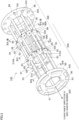
- FIG. 3 is a perspective view showing the extendable part 140 of the guidance device 120.
- FIG. 3 shows a case where the extendable part 140 is viewed from the downstream side in the conveyance direction of the disc-shaped member 300.
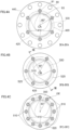
- FIGS. 4A to 4C are cross-sectional views of the extendable part 140.
- FIG. 4A is a cross-sectional view of the extendable part 140 along the IVA-IVA line in FIG. 3
- FIG. 4B is a cross-sectional view of the extendable part 140 along the IVB-IVB line in FIG. 3
- FIG. 4C is a cross-sectional view of the extendable part 140 along the IVC-IVC line in FIG. 3 .
- the extendable part 140 is provided with an upstream-side guidance part 400 guiding the disc-shaped members 300 and a downstream-side guidance part 500 guiding the disc-shaped members 300.
- the upstream-side guidance part 400 guides the disc-shaped members 300 that have been guided by the guidance device main body part 130 (refer to FIG. 1 ).
- the downstream-side guidance part 500 guides the disc-shaped members 300 that have been conveyed while being guided by the upstream-side guidance part 400.
- the installation region of the upstream-side guidance part 400 and the installation region of the downstream-side guidance part 500 partially overlap.
- a guidance region GA in which the upstream-side guidance part 400 guides the disc-shaped members 300 and a guidance region in which the downstream-side guidance part 500 guides the disc-shaped members 300 partially overlap in the conveyance direction.
- the guidance region GA that is a guidance region by the upstream-side guidance part 400 in the conveyance direction and the guidance region GB that is a guidance region by the downstream-side guidance part 500 in the conveyance direction partially overlap in the conveyance direction.
- a portion where the guidance region GA in which the upstream-side guidance part 400 guides the disc-shaped members 300 and the guidance region GB in which the downstream-side guidance part 500 guides the disc-shaped members 300 overlap is hereinafter referred to as an "overlapping portion GE.”
- guidance of the disc-shaped members 300 by the downstream-side guidance part 500 is started in the middle of the guidance of the disc-shaped members 300 by the upstream-side guidance part 400.
- the disc-shaped members 300 are guided by both the upstream-side guidance part 400 and the downstream-side guidance part 500 in the overlapping portion GE.
- the upstream-side guidance part 400 is provided with plural upstream-side guidance members 410 in the round bar shape.
- the plural upstream-side guidance members 410 are disposed along the conveyance route of the disc-shaped members 300 to be conveyed.
- the plural upstream-side guidance members 410 are disposed around the conveyance route of the disc-shaped members 300.
- the plural upstream-side guidance members 410 are disposed so that the positions thereof in the circumferential direction of the disc-shaped members 300 to be conveyed are different from one another. More specifically, the plural upstream-side guidance members 410 are disposed to be placed on a circle (a virtual circle) 420 positioned around the conveyance route of the disc-shaped members 300.
- the disc-shaped members 300 pass through the inside of the plurally-provided upstream-side guidance members 410 (on the center portion side of the circle 420 on which the plurally-provided upstream-side guidance members 410 are placed).
- downstream-side guidance part 500 is also provided with plural downstream-side guidance members 510 in the round bar shape.
- the plural downstream-side guidance members 510 are disposed around the conveyance route of the disc-shaped members 300. Further, as shown in FIG. 4B , the plural downstream-side guidance members 510 are also disposed so that the positions thereof in the circumferential direction of the disc-shaped members 300 to be conveyed are different from one another.
- the plural downstream-side guidance members 510 are also disposed to be placed on a circle (a virtual circle) 520 positioned around the conveyance route of the disc-shaped members 300. Then, in the exemplary embodiment, the disc-shaped members 300 pass through the inside of the plurally-provided downstream-side guidance members 510.
- the upstream-side guidance member 410 and the downstream-side guidance member 510 are just required to have good anticorrosion properties, scratch resistance, abrasion resistance, lubricating properties, strength and the like; the members are formed by, for example, stainless steel.
- the upstream-side guidance member 410 and the downstream-side guidance member 510 may be formed by other materials, not limited to the stainless steel. Moreover, the upstream-side guidance member 410 and the downstream-side guidance member 510 may have a configuration in which a surface of a base material in a columnar shape is covered with a member configured with a material other than the material of the base material.
- FIG. 4C is a cross-sectional view along the IVC-IVC line in FIG. 3 .
- FIG. 4C is a cross-sectional view in a plane orthogonal to the conveyance direction of the disc-shaped members 300, the plane passing both the upstream-side guidance part 400 and the downstream-side guidance part 500.
- FIG. 4C is a cross-sectional view in a plane orthogonal to the conveyance direction of the disc-shaped members 300, the plane passing the overlapping portion GE.
- the guidance region GA in which the upstream-side guidance part 400 guides the disc-shaped members 300 and the guidance region GB in which the downstream-side guidance part 500 guides the disc-shaped members 300 overlap in the overlapping portion GE.
- the downstream-side guidance members 510 constituting the downstream-side guidance part 500 are respectively inserted.
- both the upstream-side guidance members 410 and the downstream-side guidance members 510 appear in the overlapping portion GE.
- the plural upstream-side guidance members 410 and the plural downstream-side guidance members 510 are placed on the same circle (virtual circle) 620. Moreover, in the circumferential direction of the same circle 620, the upstream-side guidance members 410 and the downstream-side guidance members 510 are alternately disposed.
- the position of each of the upstream-side guidance members 410 is different from the position of each of the downstream-side guidance members 510.
- upstream-side guidance members 410 are provided.
- the upstream-side guidance members 410 are disposed to be positioned at respective vertex portions of the regular hexagon. To put it another way, the upstream-side guidance members 410 are disposed at intervals of 60° in the circumferential direction of the disc-shaped member 300.
- downstream-side guidance members 510 are also provided.
- a regular hexagon (not shown), whose center portion is positioned at a center CB of the circle 520 (refer to FIG. 4B ) on which each of the downstream-side guidance members 510 is placed, is disposed so that the downstream-side guidance members 510 are disposed to be positioned at respective vertex portions of the regular hexagon.
- downstream-side guidance members 510 are disposed at intervals of 60° in the circumferential direction of the disc-shaped member 300.
- the upstream-side guidance members 410 and the downstream-side guidance members 510 are disposed at intervals of 30° in the circumferential direction of the disc-shaped member 300.
- each number of the upstream-side guidance members 410 and the downstream-side guidance members 510 is not particularly limited. However, it is necessary to set each number of the upstream-side guidance members 410 and the downstream-side guidance members 510 to prevent the disc-shaped members 300 from falling.
- the preferable number of each of the upstream-side guidance members 410 and the downstream-side guidance members 510 to be provided is four to six.
- a gap positioned between the upstream-side guidance member 410 and the disc-shaped member 300 to be conveyed (a difference between an inscribed circle in the plural upstream-side guidance members 410 and the diameter of the disc-shaped member 300) is set at a size that makes it possible to smoothly convey the disc-shaped member 300.
- a gap positioned between the downstream-side guidance member 510 and the disc-shaped member 300 to be conveyed (a difference between an inscribed circle in the plural downstream-side guidance members 510 and the diameter of the disc-shaped member 300) is also set at a size that makes it possible to smoothly convey the disc-shaped member 300.
- the gap is too large, the disc-shaped members 300 are likely to be slanted, or jamming of the disc-shaped members 300 is likely to occur. Moreover, if the gap is too large, there is a possibility that the disc-shaped member 300 drops through a gap between the upstream-side guidance members 410 adjacent to each other or a gap between the downstream-side guidance members 510 adjacent to each other.
- the diameter of a circle 425 shown in FIG. 4A , the diameter of a circle 525 shown in FIG. 4B and the diameter of a circle 625 shown in FIG. 4C are equal to one another.
- the diameter of the inscribed circle of the plural upstream-side guidance members 410 and the diameter of the inscribed circle of the plural downstream-side guidance members 510 are equal to each other.
- the gap formed between the upstream-side guidance members 410 and the disc-shaped member 300 and the gap formed between the downstream-side guidance members 510 and the disc-shaped member 300 are equal to each other.
- the upstream-side guidance part 400 is provided with a first fixing member 430 in an annular shape (a flange shape).
- the first fixing member 430 is fixed at a portion of the plurally-provided upstream-side guidance members 410, the portion being positioned at the downstream side in the conveyance direction. More specifically, the first fixing member 430 is fixed at end portions in the downstream side of the plurally-provided upstream-side guidance members 410.
- the downstream-side guidance part 500 is also provided with a second fixing member 530 in an annular shape (a flange shape).
- the second fixing member 530 is fixed at a portion of the plurally-provided downstream-side guidance members 510, the portion being positioned at the upstream side in the conveyance direction. More specifically, the second fixing member 530 is fixed at end portions in the upstream side of the plurally-provided downstream-side guidance members 510.
- the first fixing member 430 connects the plural upstream-side guidance members 410
- the second fixing member 530 connects the plural downstream-side guidance members 510.
- the upstream-side guidance part 400 is provided with an upstream-side fixed member 440
- the downstream-side guidance part 500 is provided with a downstream-side fixed member 540.
- the upstream-side fixed member 440 is formed into an annular shape (a flange shape). Moreover, the upstream-side fixed member 440 is fixed at end portions on the upstream side of the plural upstream-side guidance members 410.
- the upstream-side fixed member 440 has a function of coupling the end portions on the upstream side of the plural upstream-side guidance members 410.
- the upstream-side fixed member 440 is fixed to the guidance device main body part 130 (refer to FIG. 1 ), to thereby perform positioning of the extendable part 140 with respect to the guidance device main body part 130.
- downstream-side fixed member 540 is also formed into an annular shape (a flange shape).
- the downstream-side fixed member 540 is fixed at end portions on the downstream side of the plural downstream-side guidance members 510.
- the downstream-side fixed member 540 has a function of coupling the plural downstream-side guidance members 510.
- the downstream-side fixed member 540 is fixed to a fixing location positioned on the downstream side of the downstream-side fixed member 540.
- the downstream-side fixed member 540 is fixed to the sealing agent application device 30 (refer to FIG. 1 ).
- Each of the upstream-side fixed member 440 and the downstream-side fixed member 540 is formed into the annular shape, and inside an outer circumferential edge 68, plural through holes 80 are formed along the thickness direction.
- bar-shaped fastening members such as bolts, are inserted into the through holes 80.
- the upstream-side fixed member 440 is fixed to the guidance device main body part 130 by use of the fastening members.
- the downstream-side fixed member 540 is fixed to the sealing agent application device 30.
- the through holes 80 formed in the downstream-side fixed member 540 have an elongate-hole shape. More specifically, the through holes 80 formed in the downstream-side fixed member 540 have an elongate-hole shape extending in the circumferential direction of the downstream-side fixed member 540.
- the through holes 80 formed in the elongate-hole shape as described above makes it possible to fix the downstream-side fixed member 540 to the fixing location with ease as compared to the case in which the through holes 80 are formed as circular holes.
- the through holes 80 are formed as the circular holes, in the case where bolt holes or the like formed at the fixing location are deviated from the through holes 80, it becomes difficult to fix the downstream-side fixed member 540 to the fixing location. In contrast thereto, if the through holes 80 are formed as elongate holes, it becomes possible to easily fix the downstream-side fixed member 540 to the fixing location.
- the through holes 80 formed in the downstream-side fixed member 540 had the elongate-hole shape; however, the through holes 80 formed in the upstream-side fixed member 440 may have the elongate-hole shape. In addition, the through holes 80 may have the elongate-hole shape in both the upstream-side fixed member 440 and the downstream-side fixed member 540.
- fixing holes 81 for fixing the upstream-side guidance members 410 are provided inside the through holes 80 in the radial direction of the upstream-side fixed member 440.
- the upstream-side guidance members 410 are fixed to the upstream-side fixed member 440 by inserting the end portions of the upstream-side guidance members 410 into the fixing holes 81 and performing welding.
- a passing through hole 83 for passing the disc-shaped members 300 is formed at the center portion in the radial direction of the upstream-side fixed member 440.
- the downstream-side guidance members 510 are fixed to the downstream-side fixed member 540 by inserting the end portions of the downstream-side guidance members 510 into the fixing holes 81 and performing welding.
- the passing through hole 83 for passing the disc-shaped members 300 is also formed at the center portion in the radial direction of the downstream-side fixed member 540.
- through holes 95 are formed in each of the first fixing member 430 and the second fixing member 530.
- Plural through holes 95 are formed and disposed at predetermined regular intervals (equally spaced intervals) along the circumferential direction of each of the first fixing member 430 and the second fixing member 530.
- the through holes 95 formed in each of the first fixing member 430 and the second fixing member 530 are formed along the moving-forward and -backward direction when one of the upstream-side guidance part 400 and the downstream-side guidance part 500 moves forward or the backward (details thereof will be described later) with respect to the other.
- the passing through hole 83 for passing the disc-shaped members 300 is also formed at the center portion in the radial direction.
- the plural upstream-side guidance members 410 are passed through the respective through holes 95 in the second fixing member 530, and the plural downstream-side guidance members 510 are passed through the respective through holes 95 in the first fixing member 430.
- the upstream-side guidance members 410 are passed through the through holes 95 positioned alternately, of the plural through holes 95 formed in the second fixing member 530.
- the end portions of the downstream-side guidance members 510 are inserted into the through holes 95 positioned between the through holes 95 through which the upstream-side guidance members 410 are passed, among the plural through holes 95 formed in the second fixing member 530.
- the through holes 95 of the same number as the sum of the installed number of the upstream-side guidance members 410 and the installed number of the downstream-side guidance members 510 are formed in the second fixing member 530.
- the upstream-side guidance members 410 are passed through a part of the through holes 95, and the end portions of the downstream-side guidance members 510 are inserted into the other part of the through holes 95.
- the second fixing member 530 twelve through holes 95 are formed. Then, the upstream-side guidance members 410 are passed through six through holes 95, and the end portions of the downstream-side guidance members 510 are inserted into the other six through holes 95.
- downstream-side guidance members 510 are passed through the through holes 95 positioned alternately, of the plural through holes 95 formed in the first fixing member 430.
- the end portions of the upstream-side guidance members 410 are inserted into the through holes 95 positioned between the through holes 95 through which the downstream-side guidance members 510 are passed, among the plural through holes 95 formed in the first fixing member 430.
- the through holes 95 of the same number as the sum of the installed number of the upstream-side guidance members 410 and the installed number of the downstream-side guidance members 510 are formed in the first fixing member 430, and the downstream-side guidance members 510 are passed through a part of the through holes 95, and the end portions of the upstream-side guidance members 410 are inserted into the other part of the through holes 95.
- the downstream-side guidance members 510 are passed through six through holes 95, and the end portions of the upstream-side guidance members 410 are inserted into the other six through holes 95.
- a spiral-shaped female thread is formed on an inner circumferential surface 98A of the screw through hole 98.
- the screw through hole 98 is formed from the outer circumferential surface 92 of each of the first fixing member 430 and the second fixing member 530 toward the passing through hole 83.
- the end portion 410A on the downstream side of) the upstream-side guidance member 410 is fixed to the first fixing member 430 by attaching a screw to the screw through hole 98 (the screw through hole 98 indicated by a reference sign 3A) and pressing the tip end of the screw against the upstream-side guidance member 410.
- the end portion 510A on the upstream side of) the downstream-side guidance member 510 is fixed to the second fixing member 530 by attaching a screw to the screw through hole 98 (the screw through hole 98 indicated by a reference sign 3B) and pressing the tip end of the screw against the downstream-side guidance member 510.
- the upstream-side guidance part 400 is fixed to the downstream-side guidance part 500 by attaching screws to the screw through holes 98 (the screw through holes 98 indicated by a reference sign 3C) in the first fixing member 430 and pressing the tip ends of the screws against the downstream-side guidance members 510.
- the downstream-side guidance part 500 is fixed to the upstream-side guidance part 400 by attaching screws to the screw through holes 98 (the screw through holes 98 indicated by a reference sign 3D) in the second fixing member 530 and pressing the tip ends of the screws against the upstream-side guidance members 410.
- first fixing member 430, the second fixing member 530, the upstream-side fixed member 440 and the downstream-side fixed member 540 are just required to have good anticorrosion properties, scratch resistance, abrasion resistance, lubricating properties, strength and the like; therefore, it is preferable that the members are formed of stainless steel. Note that the members may be formed by other materials, not limited to the stainless steel.
- each of the first fixing member 430, the second fixing member 530, the upstream-side fixed member 440 and the downstream-side fixed member 540 may have a configuration in which a surface of an annular-shaped member is covered with a material other than the material of the annular-shaped member.
- the exemplary embodiment has a configuration in which one of the upstream-side guidance part 400 and the downstream-side guidance part 500 is capable of moving forward and backward with respect to the other, and the moving forward and backward changes the full length of the extendable part 140.
- downstream-side guidance members 510, the second fixing member 530 and the downstream-side fixed member 540 are unitized as one piece.
- the unitized portion is moved toward the upstream-side guidance part 400, to thereby contract the extendable part 140.
- the unitized portion is moved in a direction away from the upstream-side guidance part 400, to thereby extend the extendable part 140.
- the upstream-side guidance members 410, the first fixing member 430 and the upstream-side fixed member 440 are unitized as one piece, and thereby the extendable part 140 is contracted by moving the unitized portion toward the downstream-side guidance part 500.
- the unitized portion is moved in a direction away from the downstream-side guidance part 500, to thereby extend the extendable part 140.
- two unitized portions are provided; further, the two unitized portions are disposed so that a part of each thereof overlaps in the conveyance direction while the portions are deviated from each other in the circumferential direction of the disc-shaped member 300.
- the extendable part 140 contracts or extends.
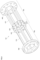
- FIG. 5 is a diagram showing a state of the extendable part 140 after the extendable part 140 is contracted.
- the upstream-side fixed member 440 and the downstream-side fixed member 540 approach each other. This reduces the full length of the extendable part 140.
- the extendable part 140 when the extendable part 140 is contracted, the length of the overlapping portion GE positioned between the first fixing member 430 and the second fixing member 530 (the separation distance between the first fixing member 430 and the second fixing member 530) is increased.
- FIG. 6 is a diagram showing a state of the extendable part 140 after the extendable part 140 is extended.
- the upstream-side fixed member 440 and the downstream-side fixed member 540 are separated from each other. This increases the full length of the extendable part 140.
- the extendable part 140 when the extendable part 140 is extended, the length of the overlapping portion GE positioned between the first fixing member 430 and the second fixing member 530 (the separation distance between the first fixing member 430 and the second fixing member 530) is reduced.
- the gap (clearance) between the disc-shaped members 300 and the upstream-side guidance members 410, the downstream-side guidance members 510 is constant.
- the moving devices 100 are installed among the various kinds of processing devices to move the disc-shaped members 300 among the processing devices.
- the full length of the moving device 100 is increased beyond necessity, or the full length of the moving device 100 is decreased to be smaller than the required length.
- increase of the full length of the moving device 100 generates necessity of cutting or grinding members constituting the moving device 100, to thereby require efforts.
- decrease of the full length of the moving device 100 causes necessity of, for example, detaching an end portion of the moving device 100 that has been once assembled, preparing a longer end portion, and thereafter, attaching the longer end portion.
- the extendable part 140 is extended or contracted.
- At least one of the upstream-side guidance part 400 and the downstream-side guidance part 500 is moved along the conveyance direction of the disc-shaped members 300.
- the first fixing member 430 (refer to FIG. 3 ) is fixed to the downstream-side guidance members 510 and the second fixing member 530 is fixed to the upstream-side guidance members 410.
- the screw is attached to each of the screw through holes 98 in the first fixing member 430 (the screw through holes 98 indicated by the reference sign 3C in FIG. 3 ), to thereby fix the first fixing member 430 to each of the plurally-provided downstream-side guidance members 510.
- the screw is attached to each of the screw through holes 98 in the second fixing member 530 (the screw through holes 98 indicated by the reference sign 3D in FIG. 3 ), to thereby fix the second fixing member 530 to each of the plurally-provided upstream-side guidance members 410.
- the first fixing member 430 is fixed to each of the downstream-side guidance members 510 and the second fixing member 530 is fixed to each of the upstream-side guidance members 410.
- plural points in the longitudinal direction in each of the plurally-provided downstream-side guidance members 510 are fixed to the upstream-side guidance part 400.
- plural points in the longitudinal direction in each of the plurally-provided upstream-side guidance members 410 are fixed to the downstream-side guidance part 500.
- downstream-side guidance members 510 are fixed to the upstream-side guidance part 400 (the upstream-side guidance members 410) at the portion where the second fixing member 530 is provided, and fixed to the upstream-side guidance part 400 (the upstream-side guidance members 410) at the portion where the first fixing member 430 is provided.
- downstream-side guidance members 510 are fixed to the upstream-side guidance part 400 at two locations; the location where the first fixing member 430 is provided and the location where the second fixing member 530 is provided.
- downstream-side guidance members 510 are fixed to the upstream-side guidance part 400 (the upstream-side guidance members 410) at two locations indicated by reference signs 3X and 3Y in FIG. 3 .
- downstream-side guidance members 510 are fixed to the upstream-side guidance members 410 via the first fixing member 430 and the second fixing member 530 at the installation positions different from each other in the conveyance direction. Consequently, the plural points in the longitudinal direction in each of the downstream-side guidance members 510 are fixed to the upstream-side guidance part 400.
- the upstream-side guidance members 410 are fixed to the downstream-side guidance part 500 (the downstream-side guidance members 510) at the portion where the first fixing member 430 is provided, and fixed to the downstream-side guidance part 500 (the downstream-side guidance members 510) at the portion where the second fixing member 530 is provided.
- the upstream-side guidance members 410 are fixed to the downstream-side guidance part 500 at two locations; the location where the first fixing member 430 is provided and the location where the second fixing member 530 is provided.
- the upstream-side guidance members 410 are fixed to the downstream-side guidance part 500 (the downstream-side guidance members 510) at two locations indicated by the reference signs 3X and 3Y in FIG. 3 .
- the upstream-side guidance members 410 are fixed to the downstream-side guidance members 510 via the first fixing member 430 and the second fixing member 530 at the installation positions different from each other in the conveyance direction.
- a cover member 89 composed of a resin material is attached to each of the upstream-side guidance members 410 and the downstream-side guidance members 510.
- the cover member 89 is attached to the guidance member 131 provided to the guidance device main body part 130 (refer to FIG. 1 ).
- FIG. 7 shows a cross-sectional view along the VII-VII line in FIG. 3 after the cover member 89 is attached. To put it another way, FIG. 7 shows a state after the cover members 89 are attached to portions of the upstream-side guidance members 410, the portions being positioned between the upstream-side fixed member 440 and the second fixing member 530.
- the cover member 89 composed of a resin material and having a C-shaped cross section is attached to each of the upstream-side guidance members 410. Consequently, the disc-shaped members 300 are less likely to be scratched as compared to the case where the upstream-side guidance members 410 are directly brought into contact with the disc-shaped members 300.
- the cover members 89 are attached to the upstream-side guidance members 410 and the upstream-side guidance members 510 positioned at the overlapping portion GE.
- cover members 89 are also attached to portions of the downstream-side guidance members 510, the portions being positioned between the first fixing member 430 and the downstream-side fixed member 540 (the portions indicated by a reference sign 3H in FIG. 3 ).
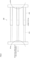
- FIG. 8 is a cross-sectional view of the extendable part 140 along the VIII-VIII line in FIG. 4B .
- FIG. 8 the state of the cross section of the entire region in the longitudinal direction of the extendable part 140 is shown. Moreover, in FIG. 8 , the upstream-side guidance members 410 that originally do not exist on the VIII-VIII line in FIG. 4B are also shown. In addition, FIG. 8 also shows the cover members 89.
- an inclination is imparted to an inner circumferential surface 79 of each of the upstream-side fixed member 440, the downstream-side fixed member 540, the first fixing member 430 and the second fixing member 530.
- the diameter of the inner circumferential surface 79 is not constant; the diameter of the inner circumferential surface 79 increases as moving toward the upstream side in the conveyance direction of the disc-shaped members 300.
- the inner circumferential surface 79 is provided with an inclination that increases the diameter of the inner circumferential surface 79 as moving toward the upstream side in the conveyance direction.
- the surface of the cover member 89 is positioned closer to the center of the conveyance route of the disc-shaped members 300 than an upstream-side end portion 79A of the inner circumferential surface 79.
- the surface of the cover member 89 is positioned closer to the center of the conveyance route of the disc-shaped members 300 than the upstream-side end portion 79A.
- the disc-shaped members 300 are less likely to be caught on the upstream-side end portions 79A, and thereby the disc-shaped members 300 are smoothly conveyed.
- an downstream-side end portion 79B of the inner circumferential surface 79 is positioned closer to the center of the conveyance route of the disc-shaped members 300 than the surface of the cover member 89.
- downstream-side end portion 79B and the surface of the cover member 89 positioned at the downstream side of the downstream-side end portion 79B are compared, the downstream-side end portion 79B is positioned closer to the center of the conveyance route of the disc-shaped members 300 than the surface of the cover member 89.
- the disc-shaped members 300 are less likely to be caught on the cover members 89, and thereby the disc-shaped members 300 are smoothly conveyed.
- FIG. 9 is a diagram showing Comparative example of the extendable part 140. Note that FIG. 9 shows a state in which the extendable part 140 is viewed from the lateral side.
- Comparative example the upstream-side guidance member 410 and the downstream-side guidance member 510 are coaxially disposed.
- Comparative example has a configuration in which the upstream-side guidance member 410 is formed into the cylindrical shape and the downstream-side guidance member 510 is inserted into the upstream-side guidance member 410.
- the downstream-side guidance member 510 comes in and out of the upstream-side guidance member 410, to thereby change the full length of the extendable part 140.
- the upstream-side guidance member 410 and the downstream-side guidance member 510 are coaxially disposed, the upstream-side guidance member 410 and the downstream-side guidance member 410 interfere with each other.
- the upstream-side guidance member 410 is formed into a hollow cylindrical member to avoid the interference.
- the guidance member is formed to be hollow as described above, the strength thereof is degraded as compared to the case where the member is solid.
- the upstream-side guidance member 410 and the downstream-side guidance member 510 are not coaxially disposed; in the circumferential direction of the disc-shaped member 300, the installation position of the upstream-side guidance member 410 and the installation position of the downstream-side guidance member 510 are different from each other.
- both the upstream-side guidance member 410 and the downstream-side guidance member 510 can be the solid members, and thereby degradation of the strength in the extendable part 140 is less likely to occur.
- the extendable part 140 is likely to be deformed. More specifically, the extendable part 140 is likely to be deformed, such as bending in the extendable part 140 around the center portion in the longitudinal direction of the extendable part 140 (around a joining portion of the upstream-side guidance member 410 and the downstream-side guidance member 510).
- the plural points in the longitudinal direction in each of the downstream-side guidance members 510 are fixed to the upstream-side guidance part 400.
- the plural points in the longitudinal direction in each of the upstream-side guidance members 410 are fixed to the downstream-side guidance part 500. In this case, even though the load working in the direction crossing the conveyance direction acts on the extendable part 140, the extendable part 140 is less likely to be deformed.
- the extendable part 140 may be disposed along the vertical direction or an oblique direction (a direction crossing the horizontal direction and the vertical direction).
- the upstream-side guidance members 410 and the downstream-side guidance members 510 are linearly formed; however, a constant curvature may be imparted to each of the upstream-side guidance members 410 and the downstream-side guidance part 500.
- at least one of the upstream-side guidance part 400 and the downstream-side guidance part 500 is moved along the conveyance route in an arc shape according to the curvature to change the full length of the extendable part 140.
- the moving devices 100 are provided during the manufacturing process of the can lids; however, the moving devices 100 may be provided during the manufacturing process of the beverage cans.
- the disc-shaped members 300 (the disc-shaped members 300 to which the tabs have already been attached (the disc-shaped members 300 in the completed state as the can lids)) are also conveyed.
- the full length of the moving device 100 is increased beyond necessity, or the full length of the moving device 100 is decreased to be smaller than the required length.
- Provision of the extendable part 140 of the exemplary embodiment makes it possible to install each processing device also in the manufacturing process of the beverage cans (a beverage can manufacturing factory) easier.
- an attaching device is provided, and thereby the disc-shaped member 300 (the disc-shaped member 300 to which the tab has already been attached) is attached to an opening portion of a can main body after being filled with a beverage through the opening portion.
- the disc-shaped member 300 is placed on the can main body, and thereafter, bending is performed on both the outer circumferential edge of the disc-shaped member 300 and the opening edge of the can main body, to thereby attach the disc-shaped member 300 to the opening portion of the can main body.
- the disc-shaped member 300 is attached to the opening portion of the can main body. Consequently, a beverage can filled with a beverage is completed.
Landscapes
- Engineering & Computer Science (AREA)
- Mechanical Engineering (AREA)
- Automation & Control Theory (AREA)
- Framework For Endless Conveyors (AREA)
- Structure Of Belt Conveyors (AREA)
- Attitude Control For Articles On Conveyors (AREA)
- Feeding Of Articles To Conveyors (AREA)
- Electroplating Methods And Accessories (AREA)
Description
- The present invention relates to a guidance device, a device for moving a disc-shaped member, a can lid manufacturing system and a beverage can manufacturing system.
- Patent Document 1 discloses a guidance device according to the preamble of claim 1 of the appended claims.
- Patent Document 1:
Japanese Utility Model Application Laid-Open No. 1-118833 - In a guidance device guiding a disc-shaped member used as a can lid, it is possible to change the full length of the guidance device by arranging plural guidance members in line along a conveyance direction of a disc-shaped member and moving part of the guidance members to the upstream side and the downstream side in the conveyance direction of the disc-shaped member.
- By the way, in the case where the part of the guidance members is moved, it is assumed that the part of the guidance members interferes with the other part of the guidance members positioned on the same axis as the part of the guidance members. In this case, the interference can be avoided by, for example, making one of the parts of the guidance members hollow and causing the other part of the guidance members to be inserted into the one part of the guidance members. However, in this case, due to the one part of the hollow guide members, there is a possibility that the strength of the guidance device is reduced.
- An object of the present invention is to cause a guidance device guiding a disc-shaped member to be used for a can lid to be capable of changing a full length of the device while suppressing degradation of strength of the device.
- The present invention is defined in the appended claims.
- According to the present invention, it is possible to cause a guidance device guiding a disc-shaped member to be used for a can lid to be capable of changing a full length of the device while suppressing degradation of strength of the device.
-
-
FIG. 1 is a diagram showing a can lid manufacturing system related to the exemplary embodiment; -
FIG. 2 is a diagram in the case where a conveyance device provided to a moving device is viewed from above; -
FIG. 3 is a perspective view showing an extendable part of the guidance device; -
FIGS. 4A to 4C are cross-sectional views of the extendable part; -
FIG. 5 is a diagram showing a state of the extendable part after the extendable part is contracted; -
FIG. 6 is a diagram showing a state of the extendable part after the extendable part is extended; -
FIG. 7 shows a cross-sectional view along the VII-VII line inFIG. 3 after a cover member is attached; -
FIG. 8 is a cross-sectional view of the extendable part along the VIII-VIII line inFIG. 4B ; and -
FIG. 9 is a diagram showing Comparative example of the extendable part. - Hereinafter, an exemplary embodiment according to the present invention will be described in detail with reference to attached drawings.
-
FIG. 1 is a diagram showing a can lid manufacturing system 1 related to the exemplary embodiment. - The can lid manufacturing system 1 of the exemplary embodiment is provided with a
delivery device 10 delivering a base material in an extended state from the base material in a rolled state. Moreover, the can lid manufacturing system 1 is provided with afirst press device 20, a sealingagent application device 30 and asecond press device 40, each of which performs a predetermined process on the base material. - The
first press device 20 performs a punching process and a rough-molding process on the base material delivered by thedelivery device 10 to thereby form a member in a disc shape having a flange at an outer circumferential edge thereof (hereinafter, referred to as "disc-shaped member"). Thereafter, in the exemplary embodiment, a curling process (a hemming process) (not shown) is performed on the outer circumferential portion of the disc-shaped member. - Next, in the exemplary embodiment, the sealing
agent application device 30 as an example of a processing device applies a sealing agent to one surface of the disc-shaped member. - Thereafter, in the exemplary embodiment, in the
second press device 40, a die is pressed against the disc-shaped member, to which the sealing agent has been applied, to thereby put a tap (to form a groove (a score) for an opening). Moreover, in thesecond press device 40, a tab for the opening is attached. - When processing by the
second press device 40 is finished, a can lid to which a tab has been attached is completed. The completed can lid is conveyed to apacking device 60 through aninspection device 50. - Further, the can lid manufacturing system 1 of the exemplary embodiment is provided with moving devices 100 (an example of a device for moving a disc-shaped member) moving the disc-shaped member between the respective devices.
- The moving
device 100 indicated by areference sign 1A is provided with aconveyance device 110 giving a driving force to the disc-shaped member to convey the disc-shaped member to the downstream side, and aguidance device 120 guiding the disc-shaped member conveyed by theconveyance device 110. - The
guidance device 120 is configured with a guidance devicemain body part 130 and anextendable part 140 positioned on a downstream side of the guidance devicemain body part 130. - The guidance device
main body part 130 is provided with aguidance member 131 that is in a round bar shape along a conveyance route of the disc-shaped member, theguidance member 131 being disposed around the conveyance route of the disc-shaped member. In the guidance devicemain body part 130, the disc-shaped member is guided by theguidance member 131. - The
extendable part 140 is disposed between the sealingagent application device 30 positioned on the downstream side and the guidance devicemain body part 130 to connect the sealingagent application device 30 and the guidance devicemain body part 130. - Note that, in the
moving devices 100 other than the movingdevice 100 indicated by thereference sign 1A, theconveyance device 110 and theguidance device 120 are provided in a similar manner. - In the can lid manufacturing system 1 of the exemplary embodiment, a can lid to be attached to a can main body (not shown) for beverage is manufactured. The manufactured can lid is attached to a can main body (not shown) that has been filled with the beverage. More specifically, the manufactured can lid is an opening portion of the cylindrical can main body, and is attached to an opening portion of the can main body after the can main body has been filled with the beverage through the opening portion. Consequently, a beverage can filled with a beverage is completed.
- Here, examples of the can lid manufactured by the can lid manufacturing system 1 of the exemplary embodiment include a can lid made of metal. More specifically, the examples include a can lid composed of aluminum or an aluminum alloy.
- Moreover, in the can lid manufacturing system 1 of the exemplary embodiment, a can lid in which a tab is not separated from the can lid even after the opening is formed in the can lid, namely, a can lid with a so-called stay-on-tab (SOT) is formed.
- Moreover, examples of the can main body, to which the can lid manufactured by the can lid manufacturing system 1 of the exemplary embodiment is to be attached, include a can main body made of metal.
- More specifically, the examples include a can main body manufactured by performing drawing and ironing (DI) molding on aluminum or an aluminum alloy. In addition, other than the above, the examples of the can main body include a two-piece can made of aluminum or an aluminum alloy.
- Moreover, examples of a beverage to be packaged inside the can main body include an alcoholic beverage, such as beer or Chuhai, or a soft drink (non-alcoholic beverage).
-
FIG. 2 is a diagram in the case where theconveyance device 110 provided to themoving device 100 is viewed from above. - The
conveyance device 110 gives a driving force to a disc-shaped member 300 to convey the disc-shaped member 300 toward the downstream side. - Specifically, the
conveyance device 110 is provided with a drivingforce supply device 111 that gives a driving force to the disc-shaped member 300 to convey thereof. The drivingforce supply device 111 is provided withbelt members 112 that are positioned at both sides of the conveyance route of the disc-shaped member 300 to perform circulating movement. - In the exemplary embodiment, when the disc-shaped
member 300 reaches the drivingforce supply device 111, thebelt members 112 are brought into contact with the disc-shapedmember 300 from the both sides thereof. This gives the driving force (propulsive force) to the disc-shapedmember 300, and thereby the disc-shapedmember 300 is conveyed to the downstream side. - Note that, in the moving device 100 (the
conveyance device 110 and the guidance device 120), the disc-shapedmembers 300 are laminated in a thickness direction and conveyed in the thickness direction. -
FIG. 3 is a perspective view showing theextendable part 140 of theguidance device 120. - Note that, only the single disc-shaped
member 300 is shown inFIG. 3 ; however, in actuality, the disc-shapedmembers 300 are laminated in the thickness direction and conveyed in the thickness direction as shown inFIG. 2 . In addition,FIG. 3 shows a case where theextendable part 140 is viewed from the downstream side in the conveyance direction of the disc-shapedmember 300. - Moreover,
FIGS. 4A to 4C are cross-sectional views of theextendable part 140. - Specifically,
FIG. 4A is a cross-sectional view of theextendable part 140 along the IVA-IVA line inFIG. 3 ,FIG. 4B is a cross-sectional view of theextendable part 140 along the IVB-IVB line inFIG. 3 , andFIG. 4C is a cross-sectional view of theextendable part 140 along the IVC-IVC line inFIG. 3 . - As shown in
FIG. 3 , theextendable part 140 is provided with an upstream-side guidance part 400 guiding the disc-shapedmembers 300 and a downstream-side guidance part 500 guiding the disc-shapedmembers 300. - The upstream-
side guidance part 400 guides the disc-shapedmembers 300 that have been guided by the guidance device main body part 130 (refer toFIG. 1 ). The downstream-side guidance part 500 guides the disc-shapedmembers 300 that have been conveyed while being guided by the upstream-side guidance part 400. - In the exemplary embodiment, in the conveyance direction of the disc-shaped members 300 (hereinafter, simply referred to as a "conveyance direction"), the installation region of the upstream-
side guidance part 400 and the installation region of the downstream-side guidance part 500 partially overlap. - To additionally describe, in the exemplary embodiment, a guidance region GA in which the upstream-
side guidance part 400 guides the disc-shapedmembers 300 and a guidance region in which the downstream-side guidance part 500 guides the disc-shapedmembers 300 partially overlap in the conveyance direction. - More specifically, in the exemplary embodiment, the guidance region GA that is a guidance region by the upstream-
side guidance part 400 in the conveyance direction and the guidance region GB that is a guidance region by the downstream-side guidance part 500 in the conveyance direction partially overlap in the conveyance direction. - Note that, in the exemplary embodiment, a portion where the guidance region GA in which the upstream-
side guidance part 400 guides the disc-shapedmembers 300 and the guidance region GB in which the downstream-side guidance part 500 guides the disc-shapedmembers 300 overlap is hereinafter referred to as an "overlapping portion GE." - To put it another way, in the exemplary embodiment, there is a portion where both the upstream-
side guidance part 400 and the downstream-side guidance part 500 are positioned beside the conveyance route of the disc-shapedmembers 300. - Consequently, in the exemplary embodiment, guidance of the disc-shaped
members 300 by the downstream-side guidance part 500 is started in the middle of the guidance of the disc-shapedmembers 300 by the upstream-side guidance part 400. - In other words, in the exemplary embodiment, the disc-shaped
members 300 are guided by both the upstream-side guidance part 400 and the downstream-side guidance part 500 in the overlapping portion GE. - The upstream-
side guidance part 400 is provided with plural upstream-side guidance members 410 in the round bar shape. - The plural upstream-
side guidance members 410 are disposed along the conveyance route of the disc-shapedmembers 300 to be conveyed. - In addition, as shown in
FIG. 4A , the plural upstream-side guidance members 410 are disposed around the conveyance route of the disc-shapedmembers 300. - Further, as shown in
FIG. 4A , the plural upstream-side guidance members 410 are disposed so that the positions thereof in the circumferential direction of the disc-shapedmembers 300 to be conveyed are different from one another. More specifically, the plural upstream-side guidance members 410 are disposed to be placed on a circle (a virtual circle) 420 positioned around the conveyance route of the disc-shapedmembers 300. - In the exemplary embodiment, the disc-shaped
members 300 pass through the inside of the plurally-provided upstream-side guidance members 410 (on the center portion side of thecircle 420 on which the plurally-provided upstream-side guidance members 410 are placed). - Moreover, as shown in
FIG. 3 , the downstream-side guidance part 500 is also provided with plural downstream-side guidance members 510 in the round bar shape. - As shown in
FIG. 4B , the plural downstream-side guidance members 510 are disposed around the conveyance route of the disc-shapedmembers 300. Further, as shown inFIG. 4B , the plural downstream-side guidance members 510 are also disposed so that the positions thereof in the circumferential direction of the disc-shapedmembers 300 to be conveyed are different from one another. - Moreover, as shown in
FIG. 4B , the plural downstream-side guidance members 510 are also disposed to be placed on a circle (a virtual circle) 520 positioned around the conveyance route of the disc-shapedmembers 300. Then, in the exemplary embodiment, the disc-shapedmembers 300 pass through the inside of the plurally-provided downstream-side guidance members 510. - The upstream-
side guidance member 410 and the downstream-side guidance member 510 are just required to have good anticorrosion properties, scratch resistance, abrasion resistance, lubricating properties, strength and the like; the members are formed by, for example, stainless steel. - Note that the upstream-
side guidance member 410 and the downstream-side guidance member 510 may be formed by other materials, not limited to the stainless steel. Moreover, the upstream-side guidance member 410 and the downstream-side guidance member 510 may have a configuration in which a surface of a base material in a columnar shape is covered with a member configured with a material other than the material of the base material. -
FIG. 4C is a cross-sectional view along the IVC-IVC line inFIG. 3 . - To put it another way,
FIG. 4C is a cross-sectional view in a plane orthogonal to the conveyance direction of the disc-shapedmembers 300, the plane passing both the upstream-side guidance part 400 and the downstream-side guidance part 500. In other words,FIG. 4C is a cross-sectional view in a plane orthogonal to the conveyance direction of the disc-shapedmembers 300, the plane passing the overlapping portion GE. - In the exemplary embodiment, as described above, the guidance region GA in which the upstream-
side guidance part 400 guides the disc-shapedmembers 300 and the guidance region GB in which the downstream-side guidance part 500 guides the disc-shapedmembers 300 overlap in the overlapping portion GE. - More specifically, in the exemplary embodiment, among the upstream-
side guidance members 410 constituting the upstream-side guidance part 400, the downstream-side guidance members 510 constituting the downstream-side guidance part 500 are respectively inserted. - Consequently, the guidance region GA of the upstream-
side guidance part 400 and the guidance region GB of the downstream-side guidance part 500 overlap. - In this case, as shown in
FIG. 4C , both the upstream-side guidance members 410 and the downstream-side guidance members 510 appear in the overlapping portion GE. - As shown in
FIG. 4C , in the overlapping portion GE, the plural upstream-side guidance members 410 and the plural downstream-side guidance members 510 are placed on the same circle (virtual circle) 620. Moreover, in the circumferential direction of thesame circle 620, the upstream-side guidance members 410 and the downstream-side guidance members 510 are alternately disposed. - Further, in the exemplary embodiment, as shown in
FIG. 4C , in the circumferential direction of the disc-shapedmembers 300 to be conveyed (in the circumferential direction of the circle 620), the position of each of the upstream-side guidance members 410 is different from the position of each of the downstream-side guidance members 510. - Further, in the exemplary embodiment, as shown in
FIGS. 4A and 4C , six upstream-side guidance members 410 are provided. - In the case of assuming a regular hexagon (not shown) whose center portion is positioned at a center CA of the circle 420 (refer to
FIG. 4A ) on which each of the upstream-side guidance members 410 is placed, the upstream-side guidance members 410 are disposed to be positioned at respective vertex portions of the regular hexagon. To put it another way, the upstream-side guidance members 410 are disposed at intervals of 60° in the circumferential direction of the disc-shapedmember 300. - Similarly, as shown in
FIGS. 4B and 4C , six downstream-side guidance members 510 are also provided. In addition, regarding the downstream-side guidance members 510, a regular hexagon (not shown), whose center portion is positioned at a center CB of the circle 520 (refer toFIG. 4B ) on which each of the downstream-side guidance members 510 is placed, is disposed so that the downstream-side guidance members 510 are disposed to be positioned at respective vertex portions of the regular hexagon. - Further, as shown in
FIG. 4B , the downstream-side guidance members 510 are disposed at intervals of 60° in the circumferential direction of the disc-shapedmember 300. - Still further, in the exemplary embodiment, as shown in
FIG. 4C , the upstream-side guidance members 410 and the downstream-side guidance members 510 are disposed at intervals of 30° in the circumferential direction of the disc-shapedmember 300. - Note that each number of the upstream-
side guidance members 410 and the downstream-side guidance members 510 is not particularly limited. However, it is necessary to set each number of the upstream-side guidance members 410 and the downstream-side guidance members 510 to prevent the disc-shapedmembers 300 from falling. The preferable number of each of the upstream-side guidance members 410 and the downstream-side guidance members 510 to be provided is four to six. - If there are too many upstream-
side guidance members 410 and the downstream-side guidance members 510, resistive forces acting on the disc-shapedmembers 300 from the upstream-side guidance members 410 and the downstream-side guidance members 510 are increased, and thereby it becomes difficult for the disc-shapedmembers 300 to move. - Moreover, if there are too many upstream-
side guidance members 410 and the downstream-side guidance members 510, costs of the movingdevice 100 are increased. - In the exemplary embodiment, a gap positioned between the upstream-
side guidance member 410 and the disc-shapedmember 300 to be conveyed (a difference between an inscribed circle in the plural upstream-side guidance members 410 and the diameter of the disc-shaped member 300) is set at a size that makes it possible to smoothly convey the disc-shapedmember 300. - Similarly, a gap positioned between the downstream-
side guidance member 510 and the disc-shapedmember 300 to be conveyed (a difference between an inscribed circle in the plural downstream-side guidance members 510 and the diameter of the disc-shaped member 300) is also set at a size that makes it possible to smoothly convey the disc-shapedmember 300. - Here, if the gap is too small, jamming of the disc-shaped
members 300 or scratches on the outer circumferential edge of the disc-shapedmember 300 is likely to occur. - In addition, if the gap is too large, the disc-shaped
members 300 are likely to be slanted, or jamming of the disc-shapedmembers 300 is likely to occur. Moreover, if the gap is too large, there is a possibility that the disc-shapedmember 300 drops through a gap between the upstream-side guidance members 410 adjacent to each other or a gap between the downstream-side guidance members 510 adjacent to each other. - Moreover, in the exemplary embodiment, the diameter of a
circle 425 shown inFIG. 4A , the diameter of acircle 525 shown inFIG. 4B and the diameter of acircle 625 shown inFIG. 4C are equal to one another. - To put it another way, the diameter of the inscribed circle of the plural upstream-
side guidance members 410 and the diameter of the inscribed circle of the plural downstream-side guidance members 510 are equal to each other. - To additionally describe, in the exemplary embodiment, the gap formed between the upstream-
side guidance members 410 and the disc-shapedmember 300 and the gap formed between the downstream-side guidance members 510 and the disc-shapedmember 300 are equal to each other. - Consequently, as compared to the case in which the gaps are not equal, troubles such as the disc-shaped
members 300 being caught on the downstream-side guidance members 510 are less likely to occur. - With reference to
FIG. 3 again, theextendable part 140 will be further described. - The upstream-
side guidance part 400 is provided with a first fixingmember 430 in an annular shape (a flange shape). Thefirst fixing member 430 is fixed at a portion of the plurally-provided upstream-side guidance members 410, the portion being positioned at the downstream side in the conveyance direction. More specifically, the first fixingmember 430 is fixed at end portions in the downstream side of the plurally-provided upstream-side guidance members 410. - Moreover, the downstream-
side guidance part 500 is also provided with asecond fixing member 530 in an annular shape (a flange shape). Thesecond fixing member 530 is fixed at a portion of the plurally-provided downstream-side guidance members 510, the portion being positioned at the upstream side in the conveyance direction. More specifically, the second fixingmember 530 is fixed at end portions in the upstream side of the plurally-provided downstream-side guidance members 510. - Here, the first fixing
member 430 connects the plural upstream-side guidance members 410, and the second fixingmember 530 connects the plural downstream-side guidance members 510. - Moreover, the upstream-
side guidance part 400 is provided with an upstream-side fixedmember 440, and the downstream-side guidance part 500 is provided with a downstream-side fixedmember 540. - The upstream-side fixed
member 440 is formed into an annular shape (a flange shape). Moreover, the upstream-side fixedmember 440 is fixed at end portions on the upstream side of the plural upstream-side guidance members 410. - The upstream-side fixed
member 440 has a function of coupling the end portions on the upstream side of the plural upstream-side guidance members 410. In addition, the upstream-side fixedmember 440 is fixed to the guidance device main body part 130 (refer toFIG. 1 ), to thereby perform positioning of theextendable part 140 with respect to the guidance devicemain body part 130. - Moreover, the downstream-side fixed
member 540 is also formed into an annular shape (a flange shape). The downstream-side fixedmember 540 is fixed at end portions on the downstream side of the plural downstream-side guidance members 510. - The downstream-side fixed
member 540 has a function of coupling the plural downstream-side guidance members 510. In addition, the downstream-side fixedmember 540 is fixed to a fixing location positioned on the downstream side of the downstream-side fixedmember 540. Specifically, the downstream-side fixedmember 540 is fixed to the sealing agent application device 30 (refer toFIG. 1 ). - Each of the upstream-side fixed
member 440 and the downstream-side fixedmember 540 is formed into the annular shape, and inside an outercircumferential edge 68, plural throughholes 80 are formed along the thickness direction. In the exemplary embodiment, bar-shaped fastening members, such as bolts, are inserted into the through holes 80. - Then, the upstream-side fixed
member 440 is fixed to the guidance devicemain body part 130 by use of the fastening members. Moreover, the downstream-side fixedmember 540 is fixed to the sealingagent application device 30. - Here, in the exemplary embodiment, the through
holes 80 formed in the downstream-side fixedmember 540 have an elongate-hole shape. More specifically, the throughholes 80 formed in the downstream-side fixedmember 540 have an elongate-hole shape extending in the circumferential direction of the downstream-side fixedmember 540. - The through holes 80 formed in the elongate-hole shape as described above makes it possible to fix the downstream-side fixed
member 540 to the fixing location with ease as compared to the case in which the throughholes 80 are formed as circular holes. - More specifically, if the through
holes 80 are formed as the circular holes, in the case where bolt holes or the like formed at the fixing location are deviated from the throughholes 80, it becomes difficult to fix the downstream-side fixedmember 540 to the fixing location. In contrast thereto, if the throughholes 80 are formed as elongate holes, it becomes possible to easily fix the downstream-side fixedmember 540 to the fixing location. - Note that, in the exemplary embodiment, the through
holes 80 formed in the downstream-side fixedmember 540 had the elongate-hole shape; however, the throughholes 80 formed in the upstream-side fixedmember 440 may have the elongate-hole shape. In addition, the throughholes 80 may have the elongate-hole shape in both the upstream-side fixedmember 440 and the downstream-side fixedmember 540. - Moreover, as shown in
FIG. 4A , in the upstream-side fixedmember 440, fixingholes 81 for fixing the upstream-side guidance members 410 are provided inside the throughholes 80 in the radial direction of the upstream-side fixedmember 440. - In the exemplary embodiment, the upstream-
side guidance members 410 are fixed to the upstream-side fixedmember 440 by inserting the end portions of the upstream-side guidance members 410 into the fixing holes 81 and performing welding. - Moreover, as shown in
FIG. 4A , in the upstream-side fixedmember 440, a passing throughhole 83 for passing the disc-shapedmembers 300 is formed at the center portion in the radial direction of the upstream-side fixedmember 440. - Moreover, the same is true in the downstream-side fixed
member 540; in the downstream-side fixedmember 540, as shown inFIG. 3 , the fixing holes 81 for fixing the downstream-side guidance members 510 are provided inside the throughholes 80 in the radial direction of the downstream-side fixedmember 540. In the exemplary embodiment, the downstream-side guidance members 510 are fixed to the downstream-side fixedmember 540 by inserting the end portions of the downstream-side guidance members 510 into the fixing holes 81 and performing welding. - Moreover, in the downstream-side fixed
member 540, the passing throughhole 83 for passing the disc-shapedmembers 300 is also formed at the center portion in the radial direction of the downstream-side fixedmember 540. - Moreover, as shown in
FIG. 3 , in the exemplary embodiment, throughholes 95 are formed in each of the first fixingmember 430 and the second fixingmember 530. - Plural through
holes 95 are formed and disposed at predetermined regular intervals (equally spaced intervals) along the circumferential direction of each of the first fixingmember 430 and the second fixingmember 530. - Here, the through
holes 95 formed in each of the first fixingmember 430 and the second fixingmember 530 are formed along the moving-forward and -backward direction when one of the upstream-side guidance part 400 and the downstream-side guidance part 500 moves forward or the backward (details thereof will be described later) with respect to the other. - Moreover, in each of the first fixing
member 430 and the second fixingmember 530, the passing throughhole 83 for passing the disc-shapedmembers 300 is also formed at the center portion in the radial direction. - As shown in
FIG. 3 , in the exemplary embodiment, the plural upstream-side guidance members 410 are passed through the respective throughholes 95 in the second fixingmember 530, and the plural downstream-side guidance members 510 are passed through the respective throughholes 95 in the first fixingmember 430. - More specifically, the upstream-
side guidance members 410 are passed through the throughholes 95 positioned alternately, of the plural throughholes 95 formed in the second fixingmember 530. - Further, in the exemplary embodiment, the end portions of the downstream-side guidance members 510 (the end portions on the upstream side) are inserted into the through
holes 95 positioned between the throughholes 95 through which the upstream-side guidance members 410 are passed, among the plural throughholes 95 formed in the second fixingmember 530. - To additionally describe, in the exemplary embodiment, the through
holes 95 of the same number as the sum of the installed number of the upstream-side guidance members 410 and the installed number of the downstream-side guidance members 510 are formed in the second fixingmember 530. - Then, in the exemplary embodiment, the upstream-
side guidance members 410 are passed through a part of the throughholes 95, and the end portions of the downstream-side guidance members 510 are inserted into the other part of the through holes 95. - More specifically, in the second fixing
member 530, twelve throughholes 95 are formed. Then, the upstream-side guidance members 410 are passed through six throughholes 95, and the end portions of the downstream-side guidance members 510 are inserted into the other six throughholes 95. - Moreover, the downstream-
side guidance members 510 are passed through the throughholes 95 positioned alternately, of the plural throughholes 95 formed in the first fixingmember 430. - Further, in the exemplary embodiment, the end portions of the upstream-side guidance members 410 (the end portions on the upstream side) are inserted into the through
holes 95 positioned between the throughholes 95 through which the downstream-side guidance members 510 are passed, among the plural throughholes 95 formed in the first fixingmember 430. - To additionally describe, in the exemplary embodiment, the through
holes 95 of the same number as the sum of the installed number of the upstream-side guidance members 410 and the installed number of the downstream-side guidance members 510 are formed in the first fixingmember 430, and the downstream-side guidance members 510 are passed through a part of the throughholes 95, and the end portions of the upstream-side guidance members 410 are inserted into the other part of the through holes 95. - More specifically, in the first fixing
member 430, twelve throughholes 95 are formed. Then, the downstream-side guidance members 510 are passed through six throughholes 95, and the end portions of the upstream-side guidance members 410 are inserted into the other six throughholes 95. - Moreover, as shown in
FIG. 3 , in each of the first fixingmember 430 and the second fixingmember 530, screw throughholes 98 corresponding to the respective throughholes 95 are formed. - On an inner
circumferential surface 98A of the screw throughhole 98, a spiral-shaped female thread is formed. In addition, the screw throughhole 98 is formed from the outercircumferential surface 92 of each of the first fixingmember 430 and the second fixingmember 530 toward the passing throughhole 83. - In the exemplary embodiment, (the
end portion 410A on the downstream side of) the upstream-side guidance member 410 is fixed to the first fixingmember 430 by attaching a screw to the screw through hole 98 (the screw throughhole 98 indicated by areference sign 3A) and pressing the tip end of the screw against the upstream-side guidance member 410. - Moreover, (the
end portion 510A on the upstream side of) the downstream-side guidance member 510 is fixed to the second fixingmember 530 by attaching a screw to the screw through hole 98 (the screw throughhole 98 indicated by areference sign 3B) and pressing the tip end of the screw against the downstream-side guidance member 510. - Further, in the exemplary embodiment, the upstream-
side guidance part 400 is fixed to the downstream-side guidance part 500 by attaching screws to the screw through holes 98 (the screw throughholes 98 indicated by areference sign 3C) in the first fixingmember 430 and pressing the tip ends of the screws against the downstream-side guidance members 510. - Moreover, in the exemplary embodiment, the downstream-
side guidance part 500 is fixed to the upstream-side guidance part 400 by attaching screws to the screw through holes 98 (the screw throughholes 98 indicated by areference sign 3D) in the second fixingmember 530 and pressing the tip ends of the screws against the upstream-side guidance members 410. - Note that the first fixing
member 430, the second fixingmember 530, the upstream-side fixedmember 440 and the downstream-side fixedmember 540 are just required to have good anticorrosion properties, scratch resistance, abrasion resistance, lubricating properties, strength and the like; therefore, it is preferable that the members are formed of stainless steel. Note that the members may be formed by other materials, not limited to the stainless steel. In addition, each of the first fixingmember 430, the second fixingmember 530, the upstream-side fixedmember 440 and the downstream-side fixedmember 540 may have a configuration in which a surface of an annular-shaped member is covered with a material other than the material of the annular-shaped member. - Here, the exemplary embodiment has a configuration in which one of the upstream-
side guidance part 400 and the downstream-side guidance part 500 is capable of moving forward and backward with respect to the other, and the moving forward and backward changes the full length of theextendable part 140. - More specifically, in the exemplary embodiment, the downstream-
side guidance members 510, the second fixingmember 530 and the downstream-side fixedmember 540 are unitized as one piece. - Then, for example, the unitized portion is moved toward the upstream-
side guidance part 400, to thereby contract theextendable part 140. To the contrary, the unitized portion is moved in a direction away from the upstream-side guidance part 400, to thereby extend theextendable part 140. - Similarly, the upstream-
side guidance members 410, the first fixingmember 430 and the upstream-side fixedmember 440 are unitized as one piece, and thereby theextendable part 140 is contracted by moving the unitized portion toward the downstream-side guidance part 500. - In addition, to the contrary, the unitized portion is moved in a direction away from the downstream-
side guidance part 500, to thereby extend theextendable part 140. - To additionally describe, in the exemplary embodiment, two unitized portions are provided; further, the two unitized portions are disposed so that a part of each thereof overlaps in the conveyance direction while the portions are deviated from each other in the circumferential direction of the disc-shaped
member 300. - Then, in the exemplary embodiment, when one unitized portion is moved forward or backward with respect to the other unitized portion, the
extendable part 140 contracts or extends. -
FIG. 5 is a diagram showing a state of theextendable part 140 after theextendable part 140 is contracted. - When the
extendable part 140 is contracted, the upstream-side fixedmember 440 and the downstream-side fixedmember 540 approach each other. This reduces the full length of theextendable part 140. - Note that, when the
extendable part 140 is contracted, the length of the overlapping portion GE positioned between the first fixingmember 430 and the second fixing member 530 (the separation distance between the first fixingmember 430 and the second fixing member 530) is increased. -
FIG. 6 is a diagram showing a state of theextendable part 140 after theextendable part 140 is extended. - When the
extendable part 140 is extended, the upstream-side fixedmember 440 and the downstream-side fixedmember 540 are separated from each other. This increases the full length of theextendable part 140. - Moreover, when the
extendable part 140 is extended, the length of the overlapping portion GE positioned between the first fixingmember 430 and the second fixing member 530 (the separation distance between the first fixingmember 430 and the second fixing member 530) is reduced. - Note that, in the exemplary embodiment, irrespective of the state of the extendable part 140 (irrespective of whether the
extendable part 140 is in the extended state or the contracted state), the gap (clearance) between the disc-shapedmembers 300 and the upstream-side guidance members 410, the downstream-side guidance members 510 is constant. - Here, in the exemplary embodiment, as shown in
FIG. 1 , the movingdevices 100 are installed among the various kinds of processing devices to move the disc-shapedmembers 300 among the processing devices. - Here, in a factory or the like, in installing the moving
devices 100 or processing devices, due to a dimensional tolerance of each device, installation error or the like, the full length of the movingdevice 100 is increased beyond necessity, or the full length of the movingdevice 100 is decreased to be smaller than the required length. - Increase or decrease of the full length of the moving
device 100 in this manner causes troubles in installing the movingdevices 100 or the processing devices. - Specifically, increase of the full length of the moving
device 100 generates necessity of cutting or grinding members constituting the movingdevice 100, to thereby require efforts. Moreover, decrease of the full length of the movingdevice 100 causes necessity of, for example, detaching an end portion of the movingdevice 100 that has been once assembled, preparing a longer end portion, and thereafter, attaching the longer end portion. - In contrast thereto, in the configuration of the exemplary embodiment, in the case where the full length of the moving
device 100 is increased or decreased beyond necessity, theextendable part 140 is extended or contracted. - More specifically, at least one of the upstream-
side guidance part 400 and the downstream-side guidance part 500 is moved along the conveyance direction of the disc-shapedmembers 300. - This makes it possible to change the full length of the moving
device 100 easier in the exemplary embodiment. - Note that, after the full length of the moving
device 100 is changed, in the exemplary embodiment, the first fixing member 430 (refer toFIG. 3 ) is fixed to the downstream-side guidance members 510 and the second fixingmember 530 is fixed to the upstream-side guidance members 410. - Specifically, the screw is attached to each of the screw through
holes 98 in the first fixing member 430 (the screw throughholes 98 indicated by thereference sign 3C inFIG. 3 ), to thereby fix the first fixingmember 430 to each of the plurally-provided downstream-side guidance members 510. - Moreover, the screw is attached to each of the screw through
holes 98 in the second fixing member 530 (the screw throughholes 98 indicated by thereference sign 3D inFIG. 3 ), to thereby fix the second fixingmember 530 to each of the plurally-provided upstream-side guidance members 410. - Here, in the exemplary embodiment, as described above, the first fixing
member 430 is fixed to each of the downstream-side guidance members 510 and the second fixingmember 530 is fixed to each of the upstream-side guidance members 410. - As a result, in the exemplary embodiment, plural points in the longitudinal direction in each of the plurally-provided downstream-
side guidance members 510 are fixed to the upstream-side guidance part 400. Moreover, plural points in the longitudinal direction in each of the plurally-provided upstream-side guidance members 410 are fixed to the downstream-side guidance part 500. - More specifically, the downstream-
side guidance members 510 are fixed to the upstream-side guidance part 400 (the upstream-side guidance members 410) at the portion where the second fixingmember 530 is provided, and fixed to the upstream-side guidance part 400 (the upstream-side guidance members 410) at the portion where the first fixingmember 430 is provided. - In other words, the downstream-
side guidance members 510 are fixed to the upstream-side guidance part 400 at two locations; the location where the first fixingmember 430 is provided and the location where the second fixingmember 530 is provided. - More specifically, the downstream-
side guidance members 510 are fixed to the upstream-side guidance part 400 (the upstream-side guidance members 410) at two locations indicated byreference signs FIG. 3 . - To additionally describe, in the exemplary embodiment, the downstream-
side guidance members 510 are fixed to the upstream-side guidance members 410 via the first fixingmember 430 and the second fixingmember 530 at the installation positions different from each other in the conveyance direction. Consequently, the plural points in the longitudinal direction in each of the downstream-side guidance members 510 are fixed to the upstream-side guidance part 400. - Moreover, the upstream-
side guidance members 410 are fixed to the downstream-side guidance part 500 (the downstream-side guidance members 510) at the portion where the first fixingmember 430 is provided, and fixed to the downstream-side guidance part 500 (the downstream-side guidance members 510) at the portion where the second fixingmember 530 is provided. - In other words, the upstream-
side guidance members 410 are fixed to the downstream-side guidance part 500 at two locations; the location where the first fixingmember 430 is provided and the location where the second fixingmember 530 is provided. - More specifically, the upstream-
side guidance members 410 are fixed to the downstream-side guidance part 500 (the downstream-side guidance members 510) at two locations indicated by thereference signs FIG. 3 . - To additionally describe, in the exemplary embodiment, the upstream-
side guidance members 410 are fixed to the downstream-side guidance members 510 via the first fixingmember 430 and the second fixingmember 530 at the installation positions different from each other in the conveyance direction. - Consequently, the plural points in the longitudinal direction in each of the plural upstream-
side guidance members 410 are fixed to the downstream-side guidance part 500. - In the exemplary embodiment, after the extension or contraction of the
extendable part 140 is completed and the upstream-side guidance part 400 and the downstream-side guidance part 500 are fixed to each other by use of the above screws, acover member 89 composed of a resin material is attached to each of the upstream-side guidance members 410 and the downstream-side guidance members 510. - Note that, similarly, the
cover member 89 is attached to theguidance member 131 provided to the guidance device main body part 130 (refer toFIG. 1 ). -
FIG. 7 shows a cross-sectional view along the VII-VII line inFIG. 3 after thecover member 89 is attached. To put it another way,FIG. 7 shows a state after thecover members 89 are attached to portions of the upstream-side guidance members 410, the portions being positioned between the upstream-side fixedmember 440 and the second fixingmember 530. - In the exemplary embodiment, as indicated by an
arrow 7A, thecover member 89 composed of a resin material and having a C-shaped cross section is attached to each of the upstream-side guidance members 410. Consequently, the disc-shapedmembers 300 are less likely to be scratched as compared to the case where the upstream-side guidance members 410 are directly brought into contact with the disc-shapedmembers 300. - Note that, other than the above, the
cover members 89 are attached to the upstream-side guidance members 410 and the upstream-side guidance members 510 positioned at the overlapping portion GE. - In addition, the
cover members 89 are also attached to portions of the downstream-side guidance members 510, the portions being positioned between the first fixingmember 430 and the downstream-side fixed member 540 (the portions indicated by areference sign 3H inFIG. 3 ). -
FIG. 8 is a cross-sectional view of theextendable part 140 along the VIII-VIII line inFIG. 4B . - Note that, in
FIG. 8 , the state of the cross section of the entire region in the longitudinal direction of theextendable part 140 is shown. Moreover, inFIG. 8 , the upstream-side guidance members 410 that originally do not exist on the VIII-VIII line inFIG. 4B are also shown. In addition,FIG. 8 also shows thecover members 89. - In the exemplary embodiment, as shown in
FIG. 8 , an inclination is imparted to an innercircumferential surface 79 of each of the upstream-side fixedmember 440, the downstream-side fixedmember 540, the first fixingmember 430 and the second fixingmember 530. - Specifically, in each of the upstream-side fixed
member 440, the downstream-side fixedmember 540, the first fixingmember 430 and the second fixingmember 530, the diameter of the innercircumferential surface 79 is not constant; the diameter of the innercircumferential surface 79 increases as moving toward the upstream side in the conveyance direction of the disc-shapedmembers 300. - In other words, in each of the upstream-side fixed
member 440, the downstream-side fixedmember 540, the first fixingmember 430 and the second fixingmember 530, the innercircumferential surface 79 is provided with an inclination that increases the diameter of the innercircumferential surface 79 as moving toward the upstream side in the conveyance direction. - Consequently, it becomes easier for the disc-shaped
members 300 to pass through each of the upstream-side fixedmember 440, the downstream-side fixedmember 540, the first fixingmember 430 and the second fixingmember 530 as compared to the case in which the inclination is not imparted. - Further, in the exemplary embodiment, as indicated by a
reference sign 8A inFIG. 8 , the surface of thecover member 89 is positioned closer to the center of the conveyance route of the disc-shapedmembers 300 than an upstream-side end portion 79A of the innercircumferential surface 79. - More specifically, in the case where the upstream-
side end portion 79A and the surface of thecover member 89 positioned at the upstream side of the upstream-side end portion 79A are compared, the surface of thecover member 89 is positioned closer to the center of the conveyance route of the disc-shapedmembers 300 than the upstream-side end portion 79A. - Consequently, as compared to the case where the upstream-
side end portion 79A is positioned closer to the center of the conveyance route than the surface of thecover member 89, the disc-shapedmembers 300 are less likely to be caught on the upstream-side end portions 79A, and thereby the disc-shapedmembers 300 are smoothly conveyed. - Further, in the exemplary embodiment, as indicated by a
reference sign 8B inFIG. 8 , an downstream-side end portion 79B of the innercircumferential surface 79 is positioned closer to the center of the conveyance route of the disc-shapedmembers 300 than the surface of thecover member 89. - More specifically, in the case where the downstream-
side end portion 79B and the surface of thecover member 89 positioned at the downstream side of the downstream-side end portion 79B are compared, the downstream-side end portion 79B is positioned closer to the center of the conveyance route of the disc-shapedmembers 300 than the surface of thecover member 89. - Consequently, as compared to the case where the surface of the
cover member 89 is positioned closer to the center of the conveyance route than the downstream-side end portion 79B, the disc-shapedmembers 300 are less likely to be caught on thecover members 89, and thereby the disc-shapedmembers 300 are smoothly conveyed. -
FIG. 9 is a diagram showing Comparative example of theextendable part 140. Note thatFIG. 9 shows a state in which theextendable part 140 is viewed from the lateral side. - In Comparative example, the upstream-
side guidance member 410 and the downstream-side guidance member 510 are coaxially disposed. In addition, Comparative example has a configuration in which the upstream-side guidance member 410 is formed into the cylindrical shape and the downstream-side guidance member 510 is inserted into the upstream-side guidance member 410. In this Comparative example, the downstream-side guidance member 510 comes in and out of the upstream-side guidance member 410, to thereby change the full length of theextendable part 140. - Here, in general, when the upstream-
side guidance member 410 and the downstream-side guidance member 510 are coaxially disposed, the upstream-side guidance member 410 and the downstream-side guidance member 410 interfere with each other. - In this Comparative example, the upstream-
side guidance member 410 is formed into a hollow cylindrical member to avoid the interference. By the way, when the guidance member is formed to be hollow as described above, the strength thereof is degraded as compared to the case where the member is solid. - In contrast thereto, in the configuration of the exemplary embodiment, the upstream-
side guidance member 410 and the downstream-side guidance member 510 are not coaxially disposed; in the circumferential direction of the disc-shapedmember 300, the installation position of the upstream-side guidance member 410 and the installation position of the downstream-side guidance member 510 are different from each other. - In this case, both the upstream-
side guidance member 410 and the downstream-side guidance member 510 can be the solid members, and thereby degradation of the strength in theextendable part 140 is less likely to occur. - Moreover, in Comparative example, in the case where a torque as indicated by an
arrow 9A in the figure acts on the upstream-side guidance member 410 and the downstream-side guidance member 510, theextendable part 140 is likely to be deformed. More specifically, theextendable part 140 is likely to be deformed, such as bending in theextendable part 140 around the center portion in the longitudinal direction of the extendable part 140 (around a joining portion of the upstream-side guidance member 410 and the downstream-side guidance member 510). - To additionally describe, in Comparative example, in the case where a load to move end portions on the free-end side of the upstream-
side guidance member 410 and the downstream-side guidance member 510 in the direction crossing the conveyance direction acts on theextendable part 140, theextendable part 140 is likely to be deformed. - In contrast thereto, in the configuration of the exemplary embodiment, the plural points in the longitudinal direction in each of the downstream-
side guidance members 510 are fixed to the upstream-side guidance part 400. Moreover, the plural points in the longitudinal direction in each of the upstream-side guidance members 410 are fixed to the downstream-side guidance part 500. In this case, even though the load working in the direction crossing the conveyance direction acts on theextendable part 140, theextendable part 140 is less likely to be deformed. - In addition, as in Comparative example, if provided is a configuration in which the upstream-
side guidance member 410 is formed into the cylindrical shape and the downstream-side guidance member 510 is inserted into the upstream-side guidance member 410, a step is generated at the joining portion of the upstream-side guidance member 410 and the downstream-side guidance member 510. - In contrast thereto, in the configuration of the exemplary embodiment, it is possible to suppress generation of the step and to smoothly convey the disc-shaped
members 300. - In the exemplary embodiment described above, the case where the
extendable part 140 is disposed along the horizontal direction has been described; however, theextendable part 140 may be disposed along the vertical direction or an oblique direction (a direction crossing the horizontal direction and the vertical direction). - Moreover, in the above, the case where the upstream-
side guidance members 410 and the downstream-side guidance members 510 are linearly formed has been described; however, a constant curvature may be imparted to each of the upstream-side guidance members 410 and the downstream-side guidance part 500. In this case, at least one of the upstream-side guidance part 400 and the downstream-side guidance part 500 is moved along the conveyance route in an arc shape according to the curvature to change the full length of theextendable part 140. - Moreover, in the above, the case where the moving
devices 100 are provided during the manufacturing process of the can lids has been described; however, the movingdevices 100 may be provided during the manufacturing process of the beverage cans. - In the manufacturing process of the beverage cans, the disc-shaped members 300 (the disc-shaped
members 300 to which the tabs have already been attached (the disc-shapedmembers 300 in the completed state as the can lids)) are also conveyed. In this case, similar to the above, due to a dimensional tolerance of each device, the full length of the movingdevice 100 is increased beyond necessity, or the full length of the movingdevice 100 is decreased to be smaller than the required length. - Provision of the
extendable part 140 of the exemplary embodiment makes it possible to install each processing device also in the manufacturing process of the beverage cans (a beverage can manufacturing factory) easier. - Note that, in the manufacturing process of the beverage cans, an attaching device is provided, and thereby the disc-shaped member 300 (the disc-shaped
member 300 to which the tab has already been attached) is attached to an opening portion of a can main body after being filled with a beverage through the opening portion. - More specifically, the disc-shaped
member 300 is placed on the can main body, and thereafter, bending is performed on both the outer circumferential edge of the disc-shapedmember 300 and the opening edge of the can main body, to thereby attach the disc-shapedmember 300 to the opening portion of the can main body. To additionally describe, by so-called seaming, the disc-shapedmember 300 is attached to the opening portion of the can main body. Consequently, a beverage can filled with a beverage is completed. -
- 1 Can body manufacturing system
- 30 Sealing agent application device
- 80 Through hole
- 95 Through hole
- 100 Moving device
- 110 Conveyance device
- 120 Guidance device
- 300 Disc-shaped member
- 400 Upstream-side guidance part
- 410 Upstream-side guidance member
- 430 First fixing member
- 440 Upstream-side fixed member
- 500 Downstream-side guidance part
- 510 Downstream-side guidance member
- 530 Second fixing member
- 540 Downstream-side fixed member
- 620 Circle (Virtual circle)
- GA Guidance region
- GB Guidance region
- GE Overlapping portion
Claims (4)
- A guidance device (120) comprising:an upstream-side guidance part (400) including plural upstream-side guidance members (410) disposed along a conveyance route of a disc-shaped member (300) to be used as a can lid, thereby being configured to guide the disc-shaped member (300); anda downstream-side guidance part (500) including plural downstream-side guidance members (510) disposed along the conveyance route, thereby being configured to guide the disc-shaped member (300) having been guided by the upstream-side guidance members (410) and conveyed, whereina guidance region (GA) in a conveyance direction of the disc-shaped member (300) where the upstream-side guidance part (400) is configured to guide the disc-shaped member (300) and a guidance region (GB) in the conveyance direction where the downstream-side guidance part (500) is configured to guide the disc-shaped member (300) partially overlap in the conveyance direction, and movement of at least one of the upstream-side guidance part (400) and the downstream-side guidance part (500) toward the other changes a length in the conveyance direction of a portion (GE) where the guidance regions overlap, andplural points in a longitudinal direction in each of the plural downstream-side guidance members (510) constituting the downstream-side guidance part (500) are fixed to the upstream-side guidance part (400), and plural points in a longitudinal direction in each of the plural upstream-side guidance members (410) constituting the upstream-side guidance part (400) are fixed to the downstream-side guidance part (500),characterized in that the guidance device (120) further comprises:a first fixing member (430) fixed to portions of the plural upstream-side guidance members (410) positioned on a downstream side in the conveyance direction, the first fixing member (430) coupling the plural upstream-side guidance members (410) and being fixed to the downstream-side guidance members (510); anda second fixing member (530) fixed to portions of the plural downstream-side guidance members (510) positioned on an upstream side in the conveyance direction, the second fixing member (530) coupling the plural downstream-side guidance members (510) and being fixed to the upstream-side guidance members (410), whereinthe upstream-side guidance members (410) are fixed to the downstream-side guidance members (510) via the first fixing member (430) and the second fixing member (530), to thereby fix the plural points in the longitudinal direction of the upstream-side guidance members (410) to the downstream-side guidance part (500), andthe downstream-side guidance members (510) are fixed to the upstream-side guidance members (410) via the first fixing member (430) and the second fixing member (530), to thereby fix the plural points in the longitudinal direction of the downstream-side guidance members (510) to the upstream-side guidance part (400),whereinplural through holes (95) are formed in each of the first fixing member (430) and the second fixing member (530), the plural through holes being along a moving direction when one of the guidance parts moves with respect to the other, andeach of the plural downstream-side guidance members (510) is passed through each of the through holes in the first fixing member (430), and each of the plural upstream-side guidance members (410) is passed through each of the through holes in the second fixing member (530).
- A device (100) for moving a disc-shaped member (300) comprising:a conveyance device (110) providing a driving force to a disc-shaped member (300) to be used as a can lid and conveying the disc-shaped member (300); anda guidance device (120) guiding the disc-shaped member (300) conveyed by the conveyance device (110), whereinthe guidance device (120) comprises the guidance device according to claim 1.
- A can lid manufacturing system comprising:a conveyance device (110) providing a driving force to a disc-shaped member (300) to be used as a can lid and conveying the disc-shaped member (300);a guidance device (120) guiding the disc-shaped member conveyed by the conveyance device (110); anda processor performing predetermined processing to the disc-shaped member (300), whereinthe guidance device (120) comprises the guidance device according to claim 1.
- A beverage can manufacturing system (1) comprising:a conveyance device (110) providing a driving force to a disc-shaped member (300) to be used as a can lid and conveying the disc-shaped member (300);a guidance device (120) guiding the disc-shaped member (300) conveyed by the conveyance device (110); andan attaching device attaching the disc-shaped member to an opening portion of a can lid filled with a beverage, whereinthe guidance device (120) comprises the guidance device according to claim 1.
Applications Claiming Priority (2)
| Application Number | Priority Date | Filing Date | Title |
|---|---|---|---|
| JP2017195051A JP6843724B2 (en) | 2017-10-05 | 2017-10-05 | Guidance device, disk-shaped member moving device, can lid manufacturing system, and beverage can manufacturing system |
| PCT/JP2018/025067 WO2019069517A1 (en) | 2017-10-05 | 2018-07-02 | Guidance device, device for moving disc-shaped member, can lid manufacturing system, and beverage can manufacturing system |
Publications (4)
| Publication Number | Publication Date |
|---|---|
| EP3693097A1 EP3693097A1 (en) | 2020-08-12 |
| EP3693097A4 EP3693097A4 (en) | 2021-06-30 |
| EP3693097C0 EP3693097C0 (en) | 2023-09-06 |
| EP3693097B1 true EP3693097B1 (en) | 2023-09-06 |
Family
ID=65995124
Family Applications (1)
| Application Number | Title | Priority Date | Filing Date |
|---|---|---|---|
| EP18864335.7A Active EP3693097B1 (en) | 2017-10-05 | 2018-07-02 | Guidance device, device for moving disc-shaped member, can lid manufacturing system, and beverage can manufacturing system |
Country Status (5)
| Country | Link |
|---|---|
| US (1) | US11213876B2 (en) |
| EP (1) | EP3693097B1 (en) |
| JP (1) | JP6843724B2 (en) |
| CN (1) | CN111093855B (en) |
| WO (1) | WO2019069517A1 (en) |
Cited By (1)
| Publication number | Priority date | Publication date | Assignee | Title |
|---|---|---|---|---|
| US10435594B2 (en) | 2015-04-02 | 2019-10-08 | Tesa Se | Removable pressure-sensitive adhesive strip |
Families Citing this family (1)
| Publication number | Priority date | Publication date | Assignee | Title |
|---|---|---|---|---|
| CN113582105A (en) * | 2021-08-19 | 2021-11-02 | 广州达意隆包装机械股份有限公司 | Telescopic cover supplying slide way and cover sealing system |
Family Cites Families (18)
| Publication number | Priority date | Publication date | Assignee | Title |
|---|---|---|---|---|
| US2720302A (en) * | 1953-09-09 | 1955-10-11 | Homer W Madden | Telescopic can and package conveying chute |
| US2717089A (en) * | 1953-12-23 | 1955-09-06 | American Can Co | Apparatus for manually bulk loading cans into freight cars and other compartments |
| US3618550A (en) * | 1970-01-26 | 1971-11-09 | Fleetwood Syst Inc | Method and apparatus for controlling the supply in a can end processing system |
| JPS5434747Y2 (en) * | 1977-04-26 | 1979-10-23 | ||
| JPS5434747A (en) | 1977-08-24 | 1979-03-14 | Victor Co Of Japan Ltd | Fm demodulation circuit of phase tracking loop system |
| JPS6310947A (en) | 1986-07-02 | 1988-01-18 | Nippon Telegr & Teleph Corp <Ntt> | Voice packet transmission/reception system |
| JPH0610870Y2 (en) * | 1986-07-08 | 1994-03-23 | 東洋金属化工株式会社 | Telescopic shelf |
| US4795018A (en) * | 1987-04-22 | 1989-01-03 | Anderson Jon V | Contained trackwork for can conveying |
| DE3717037A1 (en) | 1987-05-21 | 1988-12-08 | Basf Ag | PHOTOPOLYMERIZABLE RECORDING MATERIALS, PHOTORESIS LAYERS AND FLAT PRINTING PLATES BASED ON THESE RECORDING MATERIALS |
| JPH0649385Y2 (en) * | 1988-01-29 | 1994-12-14 | 大和製罐株式会社 | Supply position adjustment device for can lid supply device |
| US5161919A (en) * | 1991-08-06 | 1992-11-10 | Simplimatic Engineering Company | Bottle air conveyor |
| CN1081941A (en) * | 1992-08-11 | 1994-02-16 | 雷诺兹金属公司 | The method and apparatus of can ends moulding |
| JPH0952133A (en) * | 1995-08-16 | 1997-02-25 | Mitsubishi Heavy Ind Ltd | Device for supplying can cover |
| US7721876B2 (en) * | 2006-10-27 | 2010-05-25 | Illinois Tool Works Inc. | Adjustable side rails for article conveying system, and conveyor and system incorporating same |
| CN102814426B (en) * | 2012-07-19 | 2015-01-28 | 东莞市精丽制罐有限公司 | Production system of tank body |
| US9481524B2 (en) * | 2014-02-21 | 2016-11-01 | Septimatech Group Inc. | Guide rail system with cover element |
| CN204524085U (en) * | 2014-12-31 | 2015-08-05 | 广州市金峰机械科技有限公司 | A kind of aerosol pot face cover automatic punching machine |
| JP6727098B2 (en) * | 2016-10-26 | 2020-07-22 | 昭和アルミニウム缶株式会社 | Force measuring method and force measuring device |
-
2017
- 2017-10-05 JP JP2017195051A patent/JP6843724B2/en active Active
-
2018
- 2018-07-02 US US16/648,231 patent/US11213876B2/en active Active
- 2018-07-02 CN CN201880059928.3A patent/CN111093855B/en active Active
- 2018-07-02 WO PCT/JP2018/025067 patent/WO2019069517A1/en not_active Ceased
- 2018-07-02 EP EP18864335.7A patent/EP3693097B1/en active Active
Cited By (1)
| Publication number | Priority date | Publication date | Assignee | Title |
|---|---|---|---|---|
| US10435594B2 (en) | 2015-04-02 | 2019-10-08 | Tesa Se | Removable pressure-sensitive adhesive strip |
Also Published As
| Publication number | Publication date |
|---|---|
| EP3693097A4 (en) | 2021-06-30 |
| CN111093855B (en) | 2022-02-22 |
| US20200261960A1 (en) | 2020-08-20 |
| CN111093855A (en) | 2020-05-01 |
| EP3693097C0 (en) | 2023-09-06 |
| WO2019069517A1 (en) | 2019-04-11 |
| JP2019063855A (en) | 2019-04-25 |
| JP6843724B2 (en) | 2021-03-17 |
| EP3693097A1 (en) | 2020-08-12 |
| US11213876B2 (en) | 2022-01-04 |
Similar Documents
| Publication | Publication Date | Title |
|---|---|---|
| EP3851223B1 (en) | Shaped metal container | |
| EP2006038B1 (en) | Method of joining members together | |
| US8910385B2 (en) | Method of forming a bearing device | |
| EP3670990B1 (en) | Metal seal fitting with tight bend technology | |
| US11213876B2 (en) | Guidance device, device for moving disc-shaped member, can lid manufacturing system and beverage can manufacturing system | |
| US20170113261A1 (en) | Container, and Selectively Formed Shell, and Tooling and Associated Method for Providing Same | |
| EP2907596B1 (en) | Method for manufacturing cylindrical container | |
| EP2334936B1 (en) | Lining fasteners and methods and apparatus therefor | |
| US11841044B2 (en) | Retainer and a retainer and nut assembly | |
| CA2983404C (en) | Pressed component manufacturing method, pressed component, and press apparatus | |
| US20020146277A1 (en) | Ball joint and method of manufacturing housing therefor | |
| US7100925B2 (en) | Pressure energized metallic seal | |
| US20210347526A1 (en) | Ecology tab, can end, tooling and method | |
| EP2363620A2 (en) | Adhesive wheel balance weight and process for producing the same | |
| EP2662162B1 (en) | Roller hemming device | |
| EP1681493A1 (en) | Ball screw device | |
| WO2019040128A1 (en) | Can end with a coined rivet, tooling assembly therefor and a method of forming | |
| JP4988246B2 (en) | Method for joining pipe and plate | |
| CN102311035B (en) | Conveyor Manufacturing Method | |
| US20180021836A1 (en) | Method of manufacturing tooth-shaped component, and tooth-shaped component | |
| US11745250B2 (en) | Swaging device and swaging method | |
| EP4578566A1 (en) | Manufacturing method and blank for press-formed product | |
| US20130175086A1 (en) | Knockout for electrical box | |
| CN221202009U (en) | Corrugated pipe | |
| JP2009184763A (en) | Curve conveyor with guide width adjustment device |
Legal Events
| Date | Code | Title | Description |
|---|---|---|---|
| STAA | Information on the status of an ep patent application or granted ep patent |
Free format text: STATUS: THE INTERNATIONAL PUBLICATION HAS BEEN MADE |
|
| PUAI | Public reference made under article 153(3) epc to a published international application that has entered the european phase |
Free format text: ORIGINAL CODE: 0009012 |
|
| STAA | Information on the status of an ep patent application or granted ep patent |
Free format text: STATUS: REQUEST FOR EXAMINATION WAS MADE |
|
| 17P | Request for examination filed |
Effective date: 20200327 |
|
| AK | Designated contracting states |
Kind code of ref document: A1 Designated state(s): AL AT BE BG CH CY CZ DE DK EE ES FI FR GB GR HR HU IE IS IT LI LT LU LV MC MK MT NL NO PL PT RO RS SE SI SK SM TR |
|
| AX | Request for extension of the european patent |
Extension state: BA ME |
|
| DAV | Request for validation of the european patent (deleted) | ||
| DAX | Request for extension of the european patent (deleted) | ||
| A4 | Supplementary search report drawn up and despatched |
Effective date: 20210528 |
|
| RIC1 | Information provided on ipc code assigned before grant |
Ipc: B21D 51/26 20060101AFI20210521BHEP Ipc: B21D 43/00 20060101ALI20210521BHEP Ipc: B21D 43/12 20060101ALI20210521BHEP Ipc: B21D 51/30 20060101ALI20210521BHEP Ipc: B21D 51/46 20060101ALI20210521BHEP Ipc: B65G 11/14 20060101ALI20210521BHEP Ipc: B65G 15/14 20060101ALI20210521BHEP Ipc: B65G 21/20 20060101ALI20210521BHEP Ipc: B65G 47/28 20060101ALI20210521BHEP Ipc: B67B 3/06 20060101ALI20210521BHEP Ipc: B21D 51/44 20060101ALI20210521BHEP |
|
| RAP3 | Party data changed (applicant data changed or rights of an application transferred) |
Owner name: SHOWA ALUMINIUM CAN GLOBAL CORPORATION |
|
| RAP1 | Party data changed (applicant data changed or rights of an application transferred) |
Owner name: SHOWA ALUMINUM CAN CORPORATION |
|
| RAP3 | Party data changed (applicant data changed or rights of an application transferred) |
Owner name: ALTEMIRA CO., LTD. |
|
| RAP3 | Party data changed (applicant data changed or rights of an application transferred) |
Owner name: ALTEMIRA CO., LTD. |
|
| GRAP | Despatch of communication of intention to grant a patent |
Free format text: ORIGINAL CODE: EPIDOSNIGR1 |
|
| STAA | Information on the status of an ep patent application or granted ep patent |
Free format text: STATUS: GRANT OF PATENT IS INTENDED |
|
| RIC1 | Information provided on ipc code assigned before grant |
Ipc: B21D 51/44 20060101ALI20230131BHEP Ipc: B67B 3/06 20060101ALI20230131BHEP Ipc: B65G 47/28 20060101ALI20230131BHEP Ipc: B65G 21/20 20060101ALI20230131BHEP Ipc: B65G 15/14 20060101ALI20230131BHEP Ipc: B65G 11/14 20060101ALI20230131BHEP Ipc: B21D 51/46 20060101ALI20230131BHEP Ipc: B21D 51/30 20060101ALI20230131BHEP Ipc: B21D 43/12 20060101ALI20230131BHEP Ipc: B21D 43/00 20060101ALI20230131BHEP Ipc: B21D 51/26 20060101AFI20230131BHEP |
|
| INTG | Intention to grant announced |
Effective date: 20230215 |
|
| GRAS | Grant fee paid |
Free format text: ORIGINAL CODE: EPIDOSNIGR3 |
|
| GRAA | (expected) grant |
Free format text: ORIGINAL CODE: 0009210 |
|
| STAA | Information on the status of an ep patent application or granted ep patent |
Free format text: STATUS: THE PATENT HAS BEEN GRANTED |
|
| AK | Designated contracting states |
Kind code of ref document: B1 Designated state(s): AL AT BE BG CH CY CZ DE DK EE ES FI FR GB GR HR HU IE IS IT LI LT LU LV MC MK MT NL NO PL PT RO RS SE SI SK SM TR |
|
| REG | Reference to a national code |
Ref country code: GB Ref legal event code: FG4D |
|
| REG | Reference to a national code |
Ref country code: CH Ref legal event code: EP |
|
| REG | Reference to a national code |
Ref country code: DE Ref legal event code: R096 Ref document number: 602018057200 Country of ref document: DE |
|
| REG | Reference to a national code |
Ref country code: IE Ref legal event code: FG4D |
|
| U01 | Request for unitary effect filed |
Effective date: 20230906 |
|
| U07 | Unitary effect registered |
Designated state(s): AT BE BG DE DK EE FI FR IT LT LU LV MT NL PT SE SI Effective date: 20230912 |
|
| PG25 | Lapsed in a contracting state [announced via postgrant information from national office to epo] |
Ref country code: GR Free format text: LAPSE BECAUSE OF FAILURE TO SUBMIT A TRANSLATION OF THE DESCRIPTION OR TO PAY THE FEE WITHIN THE PRESCRIBED TIME-LIMIT Effective date: 20231207 |
|
| PG25 | Lapsed in a contracting state [announced via postgrant information from national office to epo] |
Ref country code: RS Free format text: LAPSE BECAUSE OF FAILURE TO SUBMIT A TRANSLATION OF THE DESCRIPTION OR TO PAY THE FEE WITHIN THE PRESCRIBED TIME-LIMIT Effective date: 20230906 Ref country code: NO Free format text: LAPSE BECAUSE OF FAILURE TO SUBMIT A TRANSLATION OF THE DESCRIPTION OR TO PAY THE FEE WITHIN THE PRESCRIBED TIME-LIMIT Effective date: 20231206 Ref country code: HR Free format text: LAPSE BECAUSE OF FAILURE TO SUBMIT A TRANSLATION OF THE DESCRIPTION OR TO PAY THE FEE WITHIN THE PRESCRIBED TIME-LIMIT Effective date: 20230906 Ref country code: GR Free format text: LAPSE BECAUSE OF FAILURE TO SUBMIT A TRANSLATION OF THE DESCRIPTION OR TO PAY THE FEE WITHIN THE PRESCRIBED TIME-LIMIT Effective date: 20231207 |
|
| PG25 | Lapsed in a contracting state [announced via postgrant information from national office to epo] |
Ref country code: IS Free format text: LAPSE BECAUSE OF FAILURE TO SUBMIT A TRANSLATION OF THE DESCRIPTION OR TO PAY THE FEE WITHIN THE PRESCRIBED TIME-LIMIT Effective date: 20240106 |
|
| PG25 | Lapsed in a contracting state [announced via postgrant information from national office to epo] |
Ref country code: ES Free format text: LAPSE BECAUSE OF FAILURE TO SUBMIT A TRANSLATION OF THE DESCRIPTION OR TO PAY THE FEE WITHIN THE PRESCRIBED TIME-LIMIT Effective date: 20230906 |
|
| PG25 | Lapsed in a contracting state [announced via postgrant information from national office to epo] |
Ref country code: SM Free format text: LAPSE BECAUSE OF FAILURE TO SUBMIT A TRANSLATION OF THE DESCRIPTION OR TO PAY THE FEE WITHIN THE PRESCRIBED TIME-LIMIT Effective date: 20230906 Ref country code: RO Free format text: LAPSE BECAUSE OF FAILURE TO SUBMIT A TRANSLATION OF THE DESCRIPTION OR TO PAY THE FEE WITHIN THE PRESCRIBED TIME-LIMIT Effective date: 20230906 Ref country code: IS Free format text: LAPSE BECAUSE OF FAILURE TO SUBMIT A TRANSLATION OF THE DESCRIPTION OR TO PAY THE FEE WITHIN THE PRESCRIBED TIME-LIMIT Effective date: 20240106 Ref country code: ES Free format text: LAPSE BECAUSE OF FAILURE TO SUBMIT A TRANSLATION OF THE DESCRIPTION OR TO PAY THE FEE WITHIN THE PRESCRIBED TIME-LIMIT Effective date: 20230906 Ref country code: CZ Free format text: LAPSE BECAUSE OF FAILURE TO SUBMIT A TRANSLATION OF THE DESCRIPTION OR TO PAY THE FEE WITHIN THE PRESCRIBED TIME-LIMIT Effective date: 20230906 Ref country code: SK Free format text: LAPSE BECAUSE OF FAILURE TO SUBMIT A TRANSLATION OF THE DESCRIPTION OR TO PAY THE FEE WITHIN THE PRESCRIBED TIME-LIMIT Effective date: 20230906 |
|
| PG25 | Lapsed in a contracting state [announced via postgrant information from national office to epo] |
Ref country code: PL Free format text: LAPSE BECAUSE OF FAILURE TO SUBMIT A TRANSLATION OF THE DESCRIPTION OR TO PAY THE FEE WITHIN THE PRESCRIBED TIME-LIMIT Effective date: 20230906 |
|
| REG | Reference to a national code |
Ref country code: DE Ref legal event code: R097 Ref document number: 602018057200 Country of ref document: DE |
|
| PLBE | No opposition filed within time limit |
Free format text: ORIGINAL CODE: 0009261 |
|
| STAA | Information on the status of an ep patent application or granted ep patent |
Free format text: STATUS: NO OPPOSITION FILED WITHIN TIME LIMIT |
|
| 26N | No opposition filed |
Effective date: 20240607 |
|
| U20 | Renewal fee for the european patent with unitary effect paid |
Year of fee payment: 7 Effective date: 20240731 |
|
| PG25 | Lapsed in a contracting state [announced via postgrant information from national office to epo] |
Ref country code: MC Free format text: LAPSE BECAUSE OF FAILURE TO SUBMIT A TRANSLATION OF THE DESCRIPTION OR TO PAY THE FEE WITHIN THE PRESCRIBED TIME-LIMIT Effective date: 20230906 |
|
| REG | Reference to a national code |
Ref country code: CH Ref legal event code: PL |
|
| PG25 | Lapsed in a contracting state [announced via postgrant information from national office to epo] |
Ref country code: CH Free format text: LAPSE BECAUSE OF NON-PAYMENT OF DUE FEES Effective date: 20240731 |
|
| PG25 | Lapsed in a contracting state [announced via postgrant information from national office to epo] |
Ref country code: IE Free format text: LAPSE BECAUSE OF NON-PAYMENT OF DUE FEES Effective date: 20240702 |
|
| U20 | Renewal fee for the european patent with unitary effect paid |
Year of fee payment: 8 Effective date: 20250728 |
|
| PGFP | Annual fee paid to national office [announced via postgrant information from national office to epo] |
Ref country code: GB Payment date: 20250722 Year of fee payment: 8 |
|
| PG25 | Lapsed in a contracting state [announced via postgrant information from national office to epo] |
Ref country code: CY Free format text: LAPSE BECAUSE OF FAILURE TO SUBMIT A TRANSLATION OF THE DESCRIPTION OR TO PAY THE FEE WITHIN THE PRESCRIBED TIME-LIMIT; INVALID AB INITIO Effective date: 20180702 |
|
| PG25 | Lapsed in a contracting state [announced via postgrant information from national office to epo] |
Ref country code: HU Free format text: LAPSE BECAUSE OF FAILURE TO SUBMIT A TRANSLATION OF THE DESCRIPTION OR TO PAY THE FEE WITHIN THE PRESCRIBED TIME-LIMIT; INVALID AB INITIO Effective date: 20180702 |