EP3692944A1 - Surgical drill guide for edentulous patients - Google Patents
Surgical drill guide for edentulous patients Download PDFInfo
- Publication number
- EP3692944A1 EP3692944A1 EP20000112.1A EP20000112A EP3692944A1 EP 3692944 A1 EP3692944 A1 EP 3692944A1 EP 20000112 A EP20000112 A EP 20000112A EP 3692944 A1 EP3692944 A1 EP 3692944A1
- Authority
- EP
- European Patent Office
- Prior art keywords
- surgical
- track
- lower jaw
- guide
- mounting
- Prior art date
- Legal status (The legal status is an assumption and is not a legal conclusion. Google has not performed a legal analysis and makes no representation as to the accuracy of the status listed.)
- Granted
Links
Images







Classifications
-
- A—HUMAN NECESSITIES
- A61—MEDICAL OR VETERINARY SCIENCE; HYGIENE
- A61C—DENTISTRY; APPARATUS OR METHODS FOR ORAL OR DENTAL HYGIENE
- A61C1/00—Dental machines for boring or cutting ; General features of dental machines or apparatus, e.g. hand-piece design
- A61C1/08—Machine parts specially adapted for dentistry
- A61C1/082—Positioning or guiding, e.g. of drills
- A61C1/084—Positioning or guiding, e.g. of drills of implanting tools
-
- A—HUMAN NECESSITIES
- A61—MEDICAL OR VETERINARY SCIENCE; HYGIENE
- A61B—DIAGNOSIS; SURGERY; IDENTIFICATION
- A61B17/00—Surgical instruments, devices or methods
- A61B17/16—Instruments for performing osteoclasis; Drills or chisels for bones; Trepans
- A61B17/1662—Instruments for performing osteoclasis; Drills or chisels for bones; Trepans for particular parts of the body
- A61B17/1673—Instruments for performing osteoclasis; Drills or chisels for bones; Trepans for particular parts of the body for the jaw
Definitions
- This embodiment is in field of dental prostheses and methods and apparatus for performing dental fixed implant retained bridges, removable overdentures or screw retained overdentures and for set up dental intraoral prostheses in the mouth of patients.
- the inventions include a novel surgical guide aimed at locating ideal position for dental implants in edentulous patients.
- This embodiment relates particularly to surgical drill guide device aimed at locating ideal position for dental implants in patients without teeth and providing an improved surgical guide for installing and insertion of dental implants.
- This embodiment has a reference to the portion of dental device, methods and apparatus as a surgical guide aimed at locating the ideal position for dental implants in edentulous patients that is particularly adapted for dental use, which allows for more efficient function of the placement of dental implants in edentulous patients.
- Modern implant dentistry usually involves restoring teeth in an edentulous patient by using dental implants to reconstruct intraoral defects with the help of dental prosthesis.
- Dental prosthesis means a set of artificial teeth that is designed to reestablish esthetically and functionally missing teeth in edentulous patients.
- Dental implants surgical drill guide means a fitting device that is used by a dentist to establish the right position for drilled apertures for the insertion of dental implants.
- the present embodiment relates generally to a surgical drill guide aimed at locating ideal position for dental implants in edentulous patients and to techniques, methods and apparatus for locating the ideal placement of dental implants when patient doesn't have any teeth at all. In this situation it is very difficult to locate the right position for the insertion of dental implants.
- the positioning guides may also be called dental implant placement guides for edentulous patients, implant dental drill guides for edentulous patients, or surgical drill guides aimed at locating the ideal position for dental implants in edentulous patients.
- the prosthetic device In the majority of cases, the prosthetic device is indistinguishable from a natural tooth. In this way, patients who are edentulous because they have lost the all of their teeth structures can obtain several prosthetic replacements. It is not currently possible to insert dental implant in a precise anatomical position.
- the dental implant surgery initially involves making an incision in the gum tissue to uncover the underlying bone. After that, an initial hole is drilled in the initial layer of bone to establish the position and the initial depth for the future dental implant.
- the diameter of first hole is generally smaller in diameter than the diameter of dental implant and will be enlarged during the surgical procedure using standard drilling protocol for the dental implant insertion.
- the dental provider during the dental implant surgery uses a parallel technique or positioning guide technique to establish the parallel and right angulations of the initial holes drilled into the bone and extending outwardly from bone.
- the dentist can detect the orientation of the extending portion of the parallelism and analyses of the future position of the dental implants.
- the patient's dental surgeon has no reference points and very difficult task to drill the initial holes to create the appropriate spacing between adjacent holes and to established parallel positioning.
- One embodiment of the present disclosure is directed to a surgical drill guide aimed at locating the ideal position for dental implants in edentulous patients, comprising a surgical stent material from metal or other material from which the surgical guides are made.
- the guides must have the features of being relatively rigid so that the guide is aligned to provide support and stability of fully edentulous upper and lower jaw to navigate orientation surgical drills in area of operation.
- the casting apparatus is formed or shaped resembling a toothless upper or lower jaw which can be positioned to dental area to be restored.
- the present invention relates to an improved mounting device and apparatus for use in the area of surgery with studs comprising slot channels that imitate the position of natural teeth.
- an item of present embodiment is to provide a new concept and value-added surgical guide aimed at navigating the ideal position for dental implants in edentulous patients during dental procedures.
- An advance object of the current invention is to provide a way that can enhance the function of a surgical guide.
- An item of present current invention consists of two plates joined together by several screws.
- the present embodiment comprises a metal plate containing a top surface of the surgical stent that has a shape reminiscent of the shape of the upper or lower jaw that contacts the soft tissue of maxilla and mandibula and the bottom surface of the stent has the same shape as the top one.
- the surgical guide stent for lower jaw has a U- shape cross section and is comprised of metal material.
- the surgical drill guide for upper jaw is generally fan-shaped in design whereas the surgical guide for lower jaw is U-shaped and corresponds to the forms and contour of upper and lower jaws of the patient.
- the internal surface of present invention is anatomically contoured to match respectively over either of the upper and lower jaw and contacting soft tissue.
- the base of the surgical guide is aimed at locating the ideal position for dental implants in edentulous patients. It is formed of metal or any other rigid material which allows the base to adapt to the anatomical structure of individual patient mouth and proved a relatively tight seal between base and adjacent soft tissue.
- the present embodiment comprises a metal plate containing one major slot channel along the axis of the surgical guide stent with fourteen mounting points in the position of the fourteen teeth on upper or lower jaw.
- the major perforated L track make up a supplemental short slot channels with extended positions corresponding to the natural position of absent teeth.
- the major perforated L track extends to the buccal and lingual sides allowing the positioning of all fourteen teeth in upper or lower jaws by extending major L track.
- the present invention is also directed to a mounting apparatus for use with a stud slot channel.
- the surgical guide may accommodate employment of two or more mounting devices on major perforated L track with distance of 3-4 mm there between.
- this present embodiment comprises the devices, described by way of example and illustrated in the following drawings.
- FIGS. 1-13 An embodiment of set of surgical drill guides aimed at locating the ideal position for dental implants in edentulous patients for upper and lower jaws 10 and 30 respectively, of present invention, is shown in FIGS. 1-13 .
- a surgical drill guide for upper jaw 10 is generally fan-shaped in plan.
- One embodiment 10 includes a base portion 17.
- the base is normally defined by an arcuated buccal wall 19 and this wall 19 extends mostly vertical from the base portion 17 and the created outer edge 15.
- the upper surgical guide comprises at least two plates: top plate 11 and bottom plate (not shown), which are connected together by means of screws 41.
- the present embodiment 10 is provided with a palatal upwardly convex extending arch surface 26.
- each surgical guide consists of at least 2 plates: top plate 11 and 12 respectively and bottom plate 13 and 14 respectively, which are connected together by means of screws 41 (see FIGS. 1-6 );
- surgical drill guide for upper jaw 10 contains base portion 17 in which is located the major perforated L track 65, consisting of perforated portion and narrowed portion 66 and added by supplemental short slots 67.
- the base portion 17 is connected from mesial side to the top plate 11 and connected with bottom plate (not shown) by screws 41 which follow by the palatal upwardly convex extending arch surface 26 and the lingual wall 21 of surgical drill guide 10 and forms the outer lingual edge 24 and from the distal side base portion 17 defined by arcuated buccal wall 19.
- the surgical guide for upper jaw 10 is provided with spherical upwardly palatal ledge extension which covers the area between outer edges 15 and 23 of base portion 17 for better support and stability of surgical guide as illustrated in FIG. 2 .
- the main member 10 comprises a bottom plate 13.
- the bottom plate lengthens and forms the lingual wall 21 and the outer lingual edge 24.
- the lingual outer edge extends from the base portion 17 in which the major perforated L track 65, consisting of a perforated portion and a narrowed portion 66, combined with supplemental short slots 67 that are located and which in turn ends by outer edge 15.
- the mesial to lingual edge is situated lingual upwardly extending arch concave surface 25.
- the bottom plate 13 is connected with the top plate (not shown) by screws 41.
- top 11 and bottom 13 plates of surgical guide for upper jaw 10 have a fan-shaped design.
- a surgical drill guide for lower jaw 30 is mostly U shape in design.
- the one embodiment 30 comprises a base portion 18.
- the base is normally defined by an arcuated buccal wall 23 and this wall extends typically vertical from the base portion 18 and the outer edge 16.
- the surgical guide for lower jaw 30 comprises at least two plates: top plate (not shown) and bottom plate 14, which are connected together by means of screws 41.
- the present embodiment 30 is extended by the lingual wall 22 and the forming outer lingual edge 20.
- the present embodiment encloses the major perforated L track 65, containing the perforated portion, and the narrowed portion 66 in addition to the supplemental short slots 67.
- An additional lingual wall 21 of lower surgical guide connects to the base portion of the lower surgical guide 18 and forms an internal angle 20 of approximately 90 degree.
- one embodiment 30 comprises by top plate 12.
- the top plate lengthens and developing lingual wall 22 and outer lingual edge 20.
- the lingual outer edge extends and creating base portion 18 in which the major perforated L track 65, consisting of a perforated portion and a narrowed portion 66 in addition to the supplemental short slots 67 that are located and which in turn ends by outer buccal edge 16.
- the top plate 12 is attached to the bottom plate 14 (not shown) by screws 41.
- surgical drill guide for the lower jaw 30 contains a base portion 18 in which is located the major perforated L track 65, consisting of perforated portion and narrowed portion 66 in addition to supplemental short slots 67.
- the bottom plate 14 is connected to the top plate 16 (not shown) by screws 41. From distal side base portion 18 is defined by arcuated buccal wall 23.
- the base portion is extended by creating outer buccal edge 16.
- the bottom plate lengthens and developing lingual wall 22 and outer lingual edge 20.
- the arcuated buccal walls 19 and 23 relatively connected to the bases portions of the surgical guides 17 and 18 correspondingly and form an angle of approximately 90 degrees.
- each base 17 and 18 correspondingly is generally defined by the arcuated buccal edges 15 and 16 respectively and the arcuated lingual edges 17 and 20 accordingly.
- each surgical guide includes a base portion 17 and 18 respectively.
- Each base is defined by an arcuated front walls 19 and 23 respectively (see FIGS. 1-6 ).
- Mounting navigated device comprises a guided tube 60 and plate 61.
- the mounting navigated device extends from the rotatable head 62 in the top and may comprise collar 63 and drill guided sleeve 64 as seen in FIG. 7- 9.
- the mounting device 59 may be constructed from a rigid material such as metal or plastic and mounted and aligned to orientation marks according to position of natural teeth in the patient mouth.
- the mounting navigated device extends from rotatable head 62 in the top and may comprise the collar 63 and the drill guided sleeve 64 (see FIGS. 7-9 ).
- a major perforated L track 65 fitting mounting navigated assembly includes but is not limited to a rotatable head 62 and drill guided sleeve 64.
- the rotatable head is used to fix in the desired position the mounting navigated device for subsequent drilling with a drill through guided sleeve 64 and guided tube 60 (not shown).
- the guided sleeve and the guided tube is 2 mm or more, although the sleeve and the tube can be varied depending on the implant system.
- the diameter of plate 61 (not shown) is not limited by the width of the diameter of the track.
- the locking mechanism or plate 61 (not shown) is shaped to match the outlines of L-track.
- the major perforated L track 65 is comprised of a plurality of supplemental short slots 67 which are interspersed with narrowed portions of track 66 corresponding to the natural position of absent teeth.
- FIGS. 11-13 show the contours of the main L track 65 space underneath, containing shapes of the supplemental short slots 67 and the narrowed portions of the track 66.
- FIG. 14 illustrates an example how the drill can be generally handled by a headpiece to be installed and inserted into a mounting device of surgical guide.
Landscapes
- Health & Medical Sciences (AREA)
- Oral & Maxillofacial Surgery (AREA)
- Dentistry (AREA)
- Epidemiology (AREA)
- Life Sciences & Earth Sciences (AREA)
- Animal Behavior & Ethology (AREA)
- General Health & Medical Sciences (AREA)
- Public Health (AREA)
- Veterinary Medicine (AREA)
- Dental Prosthetics (AREA)
- Orthopedic Medicine & Surgery (AREA)
Abstract
Description
- This embodiment is in field of dental prostheses and methods and apparatus for performing dental fixed implant retained bridges, removable overdentures or screw retained overdentures and for set up dental intraoral prostheses in the mouth of patients.
- This disclosure concerns improved dental care for edentulous patients, toothless patients or patients lacking teeth. The inventions include a novel surgical guide aimed at locating ideal position for dental implants in edentulous patients. This embodiment relates particularly to surgical drill guide device aimed at locating ideal position for dental implants in patients without teeth and providing an improved surgical guide for installing and insertion of dental implants. This embodiment has a reference to the portion of dental device, methods and apparatus as a surgical guide aimed at locating the ideal position for dental implants in edentulous patients that is particularly adapted for dental use, which allows for more efficient function of the placement of dental implants in edentulous patients.
- The following is a tabulation of teachings that may relate to the invention described herein:
U.S. Patents Patent Number Kind Code Issue Date Patentee 9211165 B2 2015-12-15 Jamison 8105081 B2 2012-01-31 Bavar 7097451 B2 2006-08-29 Tang 5967777 A 1999-10-19 Klein et al. 5320529 A 1994-006-14 Pompa 5133660 A 1992-07-28 Fenick U.S. Patent Application Publications 20090130630 A1 2009-05-21 Zachary et al. - Modern implant dentistry usually involves restoring teeth in an edentulous patient by using dental implants to reconstruct intraoral defects with the help of dental prosthesis.
- Dental prosthesis means a set of artificial teeth that is designed to reestablish esthetically and functionally missing teeth in edentulous patients.
- Dental implants surgical drill guide means a fitting device that is used by a dentist to establish the right position for drilled apertures for the insertion of dental implants.
- The present embodiment relates generally to a surgical drill guide aimed at locating ideal position for dental implants in edentulous patients and to techniques, methods and apparatus for locating the ideal placement of dental implants when patient doesn't have any teeth at all. In this situation it is very difficult to locate the right position for the insertion of dental implants.
- The positioning guides may also be called dental implant placement guides for edentulous patients, implant dental drill guides for edentulous patients, or surgical drill guides aimed at locating the ideal position for dental implants in edentulous patients.
- In the majority of cases, the prosthetic device is indistinguishable from a natural tooth. In this way, patients who are edentulous because they have lost the all of their teeth structures can obtain several prosthetic replacements. It is not currently possible to insert dental implant in a precise anatomical position.
- This inability to achieve a correct anatomical orientation can occur for a number of reasons. Most obviously, the patient's lack of any natural teeth prevents appropriated orientation. Unquestionably, the dental implants must align in the same angulation as the natural teeth. The dental practitioner may choose the position to place the implant in the jaw at an angle to a precise vertical direction but it's very difficult when patient doesn't have natural teeth. Volume and quality of bone tissue of jaw are critical elements for deliberate anatomical positioning and for the proper angularity in the insertion process of the dental implants, particularly for edentulous patients.
- The dental implant surgery initially involves making an incision in the gum tissue to uncover the underlying bone. After that, an initial hole is drilled in the initial layer of bone to establish the position and the initial depth for the future dental implant. The diameter of first hole is generally smaller in diameter than the diameter of dental implant and will be enlarged during the surgical procedure using standard drilling protocol for the dental implant insertion.
- The dental provider during the dental implant surgery uses a parallel technique or positioning guide technique to establish the parallel and right angulations of the initial holes drilled into the bone and extending outwardly from bone.
- The dentist can detect the orientation of the extending portion of the parallelism and analyses of the future position of the dental implants. In case of edentulous, the patient's dental surgeon has no reference points and very difficult task to drill the initial holes to create the appropriate spacing between adjacent holes and to established parallel positioning.
- As a result, there is a need for a surgical drill guide which effectively helps aim at the right position for the dental implants for toothless patients. It is usually important that the dental implant be inserted at the proper approach with respect to the individual structure of the alveolar bone of the patient.
- In implant dentistry we are exceptionally limited in methods and devices that have been developed for the correct placement of a dental implant in edentulous patients. Some techniques depend only on the skill and experience of the dental provider for positioning and installing the implant in these cases.
- In reaction to the complications and problems discussed herein, a very effective surgical drill guide aimed at locating ideal position for dental implants in edentulous patients is provided.
- One embodiment of the present disclosure is directed to a surgical drill guide aimed at locating the ideal position for dental implants in edentulous patients, comprising a surgical stent material from metal or other material from which the surgical guides are made. The guides must have the features of being relatively rigid so that the guide is aligned to provide support and stability of fully edentulous upper and lower jaw to navigate orientation surgical drills in area of operation.
- The casting apparatus is formed or shaped resembling a toothless upper or lower jaw which can be positioned to dental area to be restored.
- The present invention relates to an improved mounting device and apparatus for use in the area of surgery with studs comprising slot channels that imitate the position of natural teeth.
- Therefore, an item of present embodiment is to provide a new concept and value-added surgical guide aimed at navigating the ideal position for dental implants in edentulous patients during dental procedures.
- An advance object of the current invention is to provide a way that can enhance the function of a surgical guide.
- An item of present current invention consists of two plates joined together by several screws.
- The present embodiment comprises a metal plate containing a top surface of the surgical stent that has a shape reminiscent of the shape of the upper or lower jaw that contacts the soft tissue of maxilla and mandibula and the bottom surface of the stent has the same shape as the top one.
- In another embodiment, the surgical guide stent for lower jaw has a U- shape cross section and is comprised of metal material. Moreover the surgical drill guide for upper jaw is generally fan-shaped in design whereas the surgical guide for lower jaw is U-shaped and corresponds to the forms and contour of upper and lower jaws of the patient. The internal surface of present invention is anatomically contoured to match respectively over either of the upper and lower jaw and contacting soft tissue.
- The base of the surgical guide is aimed at locating the ideal position for dental implants in edentulous patients. It is formed of metal or any other rigid material which allows the base to adapt to the anatomical structure of individual patient mouth and proved a relatively tight seal between base and adjacent soft tissue.
- In this manner the surgical guide is retained securely against any movement and provides a very accurate navigation for the subsequent drilling protocol.
- The present embodiment comprises a metal plate containing one major slot channel along the axis of the surgical guide stent with fourteen mounting points in the position of the fourteen teeth on upper or lower jaw.
- In other embodiment, the major perforated L track make up a supplemental short slot channels with extended positions corresponding to the natural position of absent teeth. The major perforated L track extends to the buccal and lingual sides allowing the positioning of all fourteen teeth in upper or lower jaws by extending major L track.
- The present invention is also directed to a mounting apparatus for use with a stud slot channel.
- The surgical guide may accommodate employment of two or more mounting devices on major perforated L track with distance of 3-4 mm there between.
- The foregoing advantages and objectives of the present embodiment will be more gladly understood upon consideration of the following detailed description of the present invention taken in combination with the selected drawings.
- With the above and supplementary items and advantages in view, as will hereinafter appear, this present embodiment comprises the devices, described by way of example and illustrated in the following drawings.
-
FIG. 1 is a perspective view of the first embodiment of surgical guide for upper jaw in accordance with present invention. -
FIG. 2 is a top plan view of the tissue side of a surgical guide for upper jaw ofFIG. 1 . -
FIG. 3 is a bottom plan view of another embodiment in accordance with the present invention. -
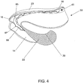
FIG. 4 is perspective view of the second embodiment of surgical guide for lower jaw in accordance with present invention. -
FIG. 5 is a top plan view of the second embodiment of surgical guide for lower jaw ofFIG. 4 . -
FIG. 6 is a bottom plan view of the tissue side of surgical guide for lower jaw ofFIG. 4 . -
FIG. 7 is a bottom view of the mounting device of the present invention. -
FIG. 8 is a bottom perspective view of the mounting device of the present invention. -
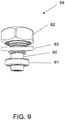
FIG. 9 is a perspective view of the embodiment of mounting device for surgical guide for upper and lower jaw in accordance with present invention. -
FIG. 10 is a top view of apparatus ofFIG.1 with the mounting device secured to the visible portion of perforated L track of present invention. -
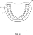
FIG. 11 is a top view of disassembled inner surface of present invention, showing the "hidden" contours of visible potion of L track. -
FIG. 12 is a perspective view of a portion of major perforated L track, for which one of the embodiments is fitted. -
FIG. 13 is a bottom perspective view of a portion of major perforated L track and supplemental short slots. -
FIG.14 illustrates a drill installing a mounting device of surgical guide. -
- 10 Surgical guide for dental implants for upper jaw
- 30 Surgical guide for dental implants for lower jaw
- 17 Base portion of surgical guide for upper jaw
- 18 Base portion of surgical guide for lower jaw
- 19 Arcuated buccal wall for upper surgical guide
- 23 Arcuated buccal wall for lower surgical guide
- 11 Top plate for upper surgical guide
- 12 Top plate for lower surgical guide
- 13 Bottom plate for upper surgical guide
- 14 Bottom plate for lower surgical guide
- 41 Connecting screw
- 15 Outer buccal edge of surgical guide for upper jaw
- 16 Outer buccal edge of surgical guide for lower jaw
- 24 Outer lingual edge of surgical guide for upper jaw
- 20 Outer lingual edge of surgical guide for lower jaw
- 21 Lingual wall of surgical guide for upper jaw
- 22 Lingual wall of surgical guide for lower jaw
- 25 Lingual upwardly extending arch concave surface of surgical guide for upper jaw
- 26 Palatal upwardly extending arch convex surface of surgical guide for upper jaw
- 59 Mounting navigated device
- 60 Guided tube
- 61 Plate
- 62 Rotatable head
- 63 Collar
- 64 Drill guided sleeve
- 65 Major perforated L track
- 66 Narrowed portion of the track
- 67 Supplemental short slots
- An embodiment of set of surgical drill guides aimed at locating the ideal position for dental implants in edentulous patients for upper and
lower jaws FIGS. 1-13 . - Referring to
FIG.1 , a surgical drill guide forupper jaw 10 is generally fan-shaped in plan. Oneembodiment 10 includes abase portion 17. The base is normally defined by an arcuatedbuccal wall 19 and thiswall 19 extends mostly vertical from thebase portion 17 and the createdouter edge 15. The upper surgical guide comprises at least two plates:top plate 11 and bottom plate (not shown), which are connected together by means ofscrews 41. In addition, thepresent embodiment 10 is provided with a palatal upwardly convex extendingarch surface 26. - Preferably, each surgical guide consists of at least 2 plates:
top plate bottom plate FIGS. 1-6 ); - As illustrated in
FIG. 2 surgical drill guide forupper jaw 10 containsbase portion 17 in which is located the majorperforated L track 65, consisting of perforated portion and narrowedportion 66 and added by supplementalshort slots 67. Thebase portion 17 is connected from mesial side to thetop plate 11 and connected with bottom plate (not shown) byscrews 41 which follow by the palatal upwardly convex extendingarch surface 26 and thelingual wall 21 ofsurgical drill guide 10 and forms the outerlingual edge 24 and from the distalside base portion 17 defined by arcuatedbuccal wall 19. - Therefore, the surgical guide for
upper jaw 10 is provided with spherical upwardly palatal ledge extension which covers the area betweenouter edges base portion 17 for better support and stability of surgical guide as illustrated inFIG. 2 . - As seen in
FIG. 3 , themain member 10 comprises abottom plate 13. The bottom plate lengthens and forms thelingual wall 21 and the outerlingual edge 24. The lingual outer edge extends from thebase portion 17 in which the majorperforated L track 65, consisting of a perforated portion and a narrowedportion 66, combined with supplementalshort slots 67 that are located and which in turn ends byouter edge 15. The mesial to lingual edge is situated lingual upwardly extending archconcave surface 25. Thebottom plate 13 is connected with the top plate (not shown) by screws 41. - As a shown in
FIGS. 1-3 , the top 11 and bottom 13 plates of surgical guide forupper jaw 10 have a fan-shaped design. - Referring now to
FIG. 4 , a surgical drill guide forlower jaw 30 is mostly U shape in design. The oneembodiment 30 comprises abase portion 18. The base is normally defined by an arcuatedbuccal wall 23 and this wall extends typically vertical from thebase portion 18 and theouter edge 16. The surgical guide forlower jaw 30 comprises at least two plates: top plate (not shown) andbottom plate 14, which are connected together by means ofscrews 41. In addition, thepresent embodiment 30 is extended by thelingual wall 22 and the forming outerlingual edge 20. In addition, the present embodiment encloses the majorperforated L track 65, containing the perforated portion, and the narrowedportion 66 in addition to the supplementalshort slots 67. - An additional
lingual wall 21 of lower surgical guide connects to the base portion of the lowersurgical guide 18 and forms aninternal angle 20 of approximately 90 degree. - As shown in
FIG. 5 oneembodiment 30 comprises bytop plate 12. The top plate lengthens and developinglingual wall 22 and outerlingual edge 20. The lingual outer edge extends and creatingbase portion 18 in which the majorperforated L track 65, consisting of a perforated portion and a narrowedportion 66 in addition to the supplementalshort slots 67 that are located and which in turn ends by outerbuccal edge 16. Thetop plate 12 is attached to the bottom plate 14 (not shown) by screws 41. - As demonstrated in
FIG. 6 surgical drill guide for thelower jaw 30 contains abase portion 18 in which is located the majorperforated L track 65, consisting of perforated portion and narrowedportion 66 in addition to supplementalshort slots 67. Thebottom plate 14 is connected to the top plate 16 (not shown) by screws 41. From distalside base portion 18 is defined by arcuatedbuccal wall 23. The base portion is extended by creating outerbuccal edge 16. The bottom plate lengthens and developinglingual wall 22 and outerlingual edge 20. - As shown in
FIGS. 1-6 , the arcuatedbuccal walls surgical guides - With continue reference to
FIGS. 1-6 it is desirable that each base 17 and 18 correspondingly is generally defined by the arcuatedbuccal edges lingual edges - As shown in
FIGS. 4-6 , preferably thetop plate 12 andbottom plate 14 of surgical the surgical guide for upper and lower jaws correspond to the forms and contour of upper and lower jaws of the patient. Each surgical guide includes abase portion front walls FIGS. 1-6 ). - With continuing reference to
FIGS. 7-9 , another embodiment of the mounting navigateddevice 59 of present invention is shown. Mounting navigated device comprises a guidedtube 60 andplate 61. The mounting navigated device extends from therotatable head 62 in the top and may comprisecollar 63 and drill guidedsleeve 64 as seen inFIG. 7- 9. - As illustrated in
FIGS. 7 ,8 ,9 , the mountingdevice 59 may be constructed from a rigid material such as metal or plastic and mounted and aligned to orientation marks according to position of natural teeth in the patient mouth. - The mounting navigated device extends from
rotatable head 62 in the top and may comprise thecollar 63 and the drill guided sleeve 64 (seeFIGS. 7-9 ). - Referring to
FIG. 10 , one embodiment of a majorperforated L track 65 fitting mounting navigated assembly includes but is not limited to arotatable head 62 and drill guidedsleeve 64. In this particular embodiment, the rotatable head is used to fix in the desired position the mounting navigated device for subsequent drilling with a drill through guidedsleeve 64 and guided tube 60 (not shown). It is contemplated that the guided sleeve and the guided tube is 2 mm or more, although the sleeve and the tube can be varied depending on the implant system. In fact, because guidedtube 60 is positioned above the top surface of L track, the narrowedportion 66 and the supplementalshort slots 67, the diameter of plate 61 (not shown) is not limited by the width of the diameter of the track. The locking mechanism or plate 61 (not shown) is shaped to match the outlines of L-track. - With reference to
FIGS. 11 ,12 ,13 , the majorperforated L track 65 is comprised of a plurality of supplementalshort slots 67 which are interspersed with narrowed portions oftrack 66 corresponding to the natural position of absent teeth. - The internal profile outlines of
FIGS. 11-13 show the contours of themain L track 65 space underneath, containing shapes of the supplementalshort slots 67 and the narrowed portions of thetrack 66. -
FIG.14 illustrates an example how the drill can be generally handled by a headpiece to be installed and inserted into a mounting device of surgical guide.
Claims (10)
- A surgical drill guide aimed at locating an ideal position for dental implants in edentulous patients comprising:an apparatus with a negative contact surface to be fitted on and retained over soft tissue of a patient in a fully edentulous upper or lower jaw,the apparatus containing an opening where the dental implant is inserted;a metal surgical stent that is aligned to provide support and stability of the upper or lower jaw to navigate an orientation of a surgical drill,a casting apparatus is provided to form or shape the apparatus to the upper or lower jaw, said apparatus which can be positioned to a dental area to be restored,wherein the apparatus for the upper jaw is generally fan-shaped and whereas the apparatus for the lower jaw is U-shaped and corresponds to a form and contour of the lower jaw of the patient, a mounting navigated device located at the opening of an L track, on the negative contact surface of the apparatus that is aligned to orientation marks according to position of natural teeth in the patient's mouth,a major extending perforated L track comprising a supplemental short slot channels with extended positions corresponding to the natural position of absent teeth and extend to buccal and lingual sides positioning all fourteen teeth in the upper or lower jaws.
- The surgical drill guide of claim 1 whereinthe surgical drill guide for upper jaw is generally fan-shapedand whereas the surgical guide for lower jaw is U-shaped and corresponds to forms and contour of the upper or lower jaw of the patient.
- The surgical drill guide of claim 1 whereinthe metal plate containing a top surface of the surgical stent has a shape reminiscent of the shape of the upper or lower jaw that contacts the soft tissue of a maxilla and a mandibular;and the bottom surface of the stent has the same shape as the top surface.
- The surgical drill guide of claim 1 wherein
said surgical guide consists at least 2 plates: a top plate and a bottom plate, which are connected together with several screws and have a fan-shape for the upper jaw and a U-shape for the lower jaw. - The surgical drill guide of claim 1 wherein
the major perforated L track corresponds to the natural position of absent teeth and extends to buccal and lingual sides; whereas the position of all fourteen teeth in the upper or lower jaws reside on the extended major L track. - The surgical drill guide of claim 1 wherein the major perforated track fitting assembly engages with a track having top and bottom surfaces with openings.
- A mounting navigated device for gearing with a major perforated L track having a top surface with navigating hole, the mounting navigated device comprising:a guided tube extending upwards from a surface of a surgical guide is located above the top surface of the major perforated L track and is used to navigate to a desired location for insertion of a dental implant;a navigated hole of the guided tube which receives drill bits for osteotomy drilling;a lip of the guided tube for use as a locking tool to attach the mounting navigated device to the perforated L track;a driving element or rotatable head used as a fixation element to lock the mounting navigated device at a desired position in the patient mouth.
- A method of insertion a dental implant in a mouth of an edentulous patient comprising:mounting a surgical guide over soft tissue of the edentulous patient;directing a mounting navigated device using a perforated L track;locking the mounting navigated device in a desire position;drilling apertures for insertion of the dental implants through a guided tube of the mounting navigated device;after drilling apertures, removing the surgical guide from the mouth of the patient.
- The method of claim 8, further comprising determining the desired location and position of the dental implants to be placed in the patient's mouth at a same time.
- The method of claim 8, wherein said surgical guide for edentulous patients fits over the soft tissue to mark a best position for drilling and insertion of the dental implant.
Applications Claiming Priority (1)
| Application Number | Priority Date | Filing Date | Title |
|---|---|---|---|
| US16/350,996 US11510754B2 (en) | 2019-02-11 | 2019-02-11 | Surgical drill guide aimed at locating ideal position for dental implants in edentulous patients |
Publications (2)
| Publication Number | Publication Date |
|---|---|
| EP3692944A1 true EP3692944A1 (en) | 2020-08-12 |
| EP3692944B1 EP3692944B1 (en) | 2022-02-16 |
Family
ID=69902955
Family Applications (1)
| Application Number | Title | Priority Date | Filing Date |
|---|---|---|---|
| EP20000112.1A Active EP3692944B1 (en) | 2019-02-11 | 2020-03-16 | Surgical drill guide for edentulous patients |
Country Status (3)
| Country | Link |
|---|---|
| US (1) | US11510754B2 (en) |
| EP (1) | EP3692944B1 (en) |
| ES (1) | ES2913852T3 (en) |
Families Citing this family (1)
| Publication number | Priority date | Publication date | Assignee | Title |
|---|---|---|---|---|
| CN114098964A (en) * | 2021-11-19 | 2022-03-01 | 四川大学 | An edentulous jaw navigation system and method |
Citations (6)
| Publication number | Priority date | Publication date | Assignee | Title |
|---|---|---|---|---|
| EP0534552A1 (en) * | 1991-09-23 | 1993-03-31 | Bernard M. Kruger | Dental implant product and method of making |
| WO2004064664A1 (en) * | 2003-01-23 | 2004-08-05 | Giancarlo Parise | Multiple dental implant, implantation method and tools therefor |
| EP2377486A1 (en) * | 2010-04-14 | 2011-10-19 | Vincenzo Crudo | Template for drilling holes for dental implants |
| EP2465462A2 (en) * | 2010-11-26 | 2012-06-20 | Po-Kun Cheng | Dental positioning stent, and manufacturing method, using method and components for the same |
| US20140272778A1 (en) * | 2013-03-14 | 2014-09-18 | Daniel R. Llop | Bone foundation guide and method of use |
| WO2017069797A1 (en) * | 2015-10-23 | 2017-04-27 | Llop Daniel R | Bone foundation guide system and method |
Family Cites Families (6)
| Publication number | Priority date | Publication date | Assignee | Title |
|---|---|---|---|---|
| US7331786B2 (en) * | 1996-02-27 | 2008-02-19 | Technique D'usinage Sinlab Inc. | Manufacturing a dental implant drill guide and a dental implant superstructure |
| EP2060240A3 (en) * | 2007-11-16 | 2009-08-12 | Biomet 3i, LLC | Components for use with a surgical guide for dental implant placement |
| EP3000430B1 (en) * | 2008-04-16 | 2017-11-15 | Biomet 3i, LLC | Method of virtually developing a surgical guide for dental implant |
| US9795458B2 (en) * | 2013-03-15 | 2017-10-24 | National Dentex, Llc | Dental surgical implant guide and prosthesis combination and method of use |
| US20160278878A1 (en) * | 2014-09-19 | 2016-09-29 | Jason Watson | Sequential dental surgical guide system and related methods |
| EP3569185B1 (en) * | 2018-05-18 | 2021-03-17 | 3Shape A/S | A method for providing a dental prothesis and a positioning guide for placing the dental prothesis |
-
2019
- 2019-02-11 US US16/350,996 patent/US11510754B2/en active Active
-
2020
- 2020-03-16 EP EP20000112.1A patent/EP3692944B1/en active Active
- 2020-03-16 ES ES20000112T patent/ES2913852T3/en active Active
Patent Citations (6)
| Publication number | Priority date | Publication date | Assignee | Title |
|---|---|---|---|---|
| EP0534552A1 (en) * | 1991-09-23 | 1993-03-31 | Bernard M. Kruger | Dental implant product and method of making |
| WO2004064664A1 (en) * | 2003-01-23 | 2004-08-05 | Giancarlo Parise | Multiple dental implant, implantation method and tools therefor |
| EP2377486A1 (en) * | 2010-04-14 | 2011-10-19 | Vincenzo Crudo | Template for drilling holes for dental implants |
| EP2465462A2 (en) * | 2010-11-26 | 2012-06-20 | Po-Kun Cheng | Dental positioning stent, and manufacturing method, using method and components for the same |
| US20140272778A1 (en) * | 2013-03-14 | 2014-09-18 | Daniel R. Llop | Bone foundation guide and method of use |
| WO2017069797A1 (en) * | 2015-10-23 | 2017-04-27 | Llop Daniel R | Bone foundation guide system and method |
Also Published As
| Publication number | Publication date |
|---|---|
| EP3692944B1 (en) | 2022-02-16 |
| US11510754B2 (en) | 2022-11-29 |
| ES2913852T3 (en) | 2022-06-06 |
| US20200253690A1 (en) | 2020-08-13 |
Similar Documents
| Publication | Publication Date | Title |
|---|---|---|
| US7153132B2 (en) | Mini-dental implant surgical stent | |
| CN102316818B (en) | Systems, methods and devices for implementing dental implants | |
| KR101631261B1 (en) | surgical guide for dental implant with opening | |
| US5556278A (en) | Method for making and using a template for a dental implant osteotomy and components relating thereto | |
| ES2296211T3 (en) | SURGICAL GUIDE OF IMPLANT TO ASSOCIATED STRAWBERRY AND STRAWBERRY, AND MANUFACTURING PROCEDURE OF THE SAME. | |
| US7429175B2 (en) | Dental implant surgical guide | |
| US20080057467A1 (en) | Dental Implant Surgical Guide | |
| KR102608567B1 (en) | Artificial tooth drill-guide creation method | |
| US20050282106A1 (en) | Hole guide for mini and standard dental implants | |
| EA028861B1 (en) | Dental implant | |
| JP7450845B2 (en) | Surgical guide and implant with alignment member | |
| KR101566456B1 (en) | Drill for implant and apparatus having the same | |
| KR20110055907A (en) | Prefixes for Image Registration | |
| KR101763763B1 (en) | Apparatus for guiding implant position | |
| KR102205986B1 (en) | trephine drill for implant | |
| US20100003634A1 (en) | Orthodontic implant device | |
| Atsu | A surgical guide for dental implant placement in edentulous posterior regions | |
| Kennedy et al. | Simplified guide for precise implant placement: a technical note. | |
| CN203898472U (en) | Dental implant operation guide plate | |
| TWI772773B (en) | Dental implant surgical guide and manufacturing method thereof | |
| EP3692944B1 (en) | Surgical drill guide for edentulous patients | |
| JP5616738B2 (en) | Surgical guide and embedding hole drilling tool | |
| KR100852572B1 (en) | Dental medical equipment | |
| JP7189299B1 (en) | Denture base frame and denture base | |
| CN112773532B (en) | Bone-supported maxillary posterior long implant implant guide based on 3D printing technology |
Legal Events
| Date | Code | Title | Description |
|---|---|---|---|
| PUAI | Public reference made under article 153(3) epc to a published international application that has entered the european phase |
Free format text: ORIGINAL CODE: 0009012 |
|
| STAA | Information on the status of an ep patent application or granted ep patent |
Free format text: STATUS: THE APPLICATION HAS BEEN PUBLISHED |
|
| AK | Designated contracting states |
Kind code of ref document: A1 Designated state(s): AL AT BE BG CH CY CZ DE DK EE ES FI FR GB GR HR HU IE IS IT LI LT LU LV MC MK MT NL NO PL PT RO RS SE SI SK SM TR |
|
| AX | Request for extension of the european patent |
Extension state: BA ME |
|
| STAA | Information on the status of an ep patent application or granted ep patent |
Free format text: STATUS: REQUEST FOR EXAMINATION WAS MADE |
|
| 17P | Request for examination filed |
Effective date: 20210211 |
|
| RBV | Designated contracting states (corrected) |
Designated state(s): AL AT BE BG CH CY CZ DE DK EE ES FI FR GB GR HR HU IE IS IT LI LT LU LV MC MK MT NL NO PL PT RO RS SE SI SK SM TR |
|
| GRAP | Despatch of communication of intention to grant a patent |
Free format text: ORIGINAL CODE: EPIDOSNIGR1 |
|
| STAA | Information on the status of an ep patent application or granted ep patent |
Free format text: STATUS: GRANT OF PATENT IS INTENDED |
|
| INTG | Intention to grant announced |
Effective date: 20210914 |
|
| GRAS | Grant fee paid |
Free format text: ORIGINAL CODE: EPIDOSNIGR3 |
|
| GRAA | (expected) grant |
Free format text: ORIGINAL CODE: 0009210 |
|
| STAA | Information on the status of an ep patent application or granted ep patent |
Free format text: STATUS: THE PATENT HAS BEEN GRANTED |
|
| AK | Designated contracting states |
Kind code of ref document: B1 Designated state(s): AL AT BE BG CH CY CZ DE DK EE ES FI FR GB GR HR HU IE IS IT LI LT LU LV MC MK MT NL NO PL PT RO RS SE SI SK SM TR |
|
| REG | Reference to a national code |
Ref country code: GB Ref legal event code: FG4D |
|
| REG | Reference to a national code |
Ref country code: CH Ref legal event code: EP |
|
| REG | Reference to a national code |
Ref country code: DE Ref legal event code: R096 Ref document number: 602020001817 Country of ref document: DE |
|
| REG | Reference to a national code |
Ref country code: AT Ref legal event code: REF Ref document number: 1468425 Country of ref document: AT Kind code of ref document: T Effective date: 20220315 |
|
| REG | Reference to a national code |
Ref country code: IE Ref legal event code: FG4D |
|
| REG | Reference to a national code |
Ref country code: ES Ref legal event code: FG2A Ref document number: 2913852 Country of ref document: ES Kind code of ref document: T3 Effective date: 20220606 |
|
| REG | Reference to a national code |
Ref country code: LT Ref legal event code: MG9D |
|
| REG | Reference to a national code |
Ref country code: NL Ref legal event code: MP Effective date: 20220216 |
|
| REG | Reference to a national code |
Ref country code: AT Ref legal event code: MK05 Ref document number: 1468425 Country of ref document: AT Kind code of ref document: T Effective date: 20220216 |
|
| PG25 | Lapsed in a contracting state [announced via postgrant information from national office to epo] |
Ref country code: SE Free format text: LAPSE BECAUSE OF FAILURE TO SUBMIT A TRANSLATION OF THE DESCRIPTION OR TO PAY THE FEE WITHIN THE PRESCRIBED TIME-LIMIT Effective date: 20220216 Ref country code: RS Free format text: LAPSE BECAUSE OF FAILURE TO SUBMIT A TRANSLATION OF THE DESCRIPTION OR TO PAY THE FEE WITHIN THE PRESCRIBED TIME-LIMIT Effective date: 20220216 Ref country code: PT Free format text: LAPSE BECAUSE OF FAILURE TO SUBMIT A TRANSLATION OF THE DESCRIPTION OR TO PAY THE FEE WITHIN THE PRESCRIBED TIME-LIMIT Effective date: 20220616 Ref country code: NO Free format text: LAPSE BECAUSE OF FAILURE TO SUBMIT A TRANSLATION OF THE DESCRIPTION OR TO PAY THE FEE WITHIN THE PRESCRIBED TIME-LIMIT Effective date: 20220516 Ref country code: NL Free format text: LAPSE BECAUSE OF FAILURE TO SUBMIT A TRANSLATION OF THE DESCRIPTION OR TO PAY THE FEE WITHIN THE PRESCRIBED TIME-LIMIT Effective date: 20220216 Ref country code: LT Free format text: LAPSE BECAUSE OF FAILURE TO SUBMIT A TRANSLATION OF THE DESCRIPTION OR TO PAY THE FEE WITHIN THE PRESCRIBED TIME-LIMIT Effective date: 20220216 Ref country code: HR Free format text: LAPSE BECAUSE OF FAILURE TO SUBMIT A TRANSLATION OF THE DESCRIPTION OR TO PAY THE FEE WITHIN THE PRESCRIBED TIME-LIMIT Effective date: 20220216 Ref country code: BG Free format text: LAPSE BECAUSE OF FAILURE TO SUBMIT A TRANSLATION OF THE DESCRIPTION OR TO PAY THE FEE WITHIN THE PRESCRIBED TIME-LIMIT Effective date: 20220516 |
|
| PG25 | Lapsed in a contracting state [announced via postgrant information from national office to epo] |
Ref country code: PL Free format text: LAPSE BECAUSE OF FAILURE TO SUBMIT A TRANSLATION OF THE DESCRIPTION OR TO PAY THE FEE WITHIN THE PRESCRIBED TIME-LIMIT Effective date: 20220216 Ref country code: LV Free format text: LAPSE BECAUSE OF FAILURE TO SUBMIT A TRANSLATION OF THE DESCRIPTION OR TO PAY THE FEE WITHIN THE PRESCRIBED TIME-LIMIT Effective date: 20220216 Ref country code: GR Free format text: LAPSE BECAUSE OF FAILURE TO SUBMIT A TRANSLATION OF THE DESCRIPTION OR TO PAY THE FEE WITHIN THE PRESCRIBED TIME-LIMIT Effective date: 20220517 Ref country code: FI Free format text: LAPSE BECAUSE OF FAILURE TO SUBMIT A TRANSLATION OF THE DESCRIPTION OR TO PAY THE FEE WITHIN THE PRESCRIBED TIME-LIMIT Effective date: 20220216 Ref country code: AT Free format text: LAPSE BECAUSE OF FAILURE TO SUBMIT A TRANSLATION OF THE DESCRIPTION OR TO PAY THE FEE WITHIN THE PRESCRIBED TIME-LIMIT Effective date: 20220216 |
|
| PG25 | Lapsed in a contracting state [announced via postgrant information from national office to epo] |
Ref country code: IS Free format text: LAPSE BECAUSE OF FAILURE TO SUBMIT A TRANSLATION OF THE DESCRIPTION OR TO PAY THE FEE WITHIN THE PRESCRIBED TIME-LIMIT Effective date: 20220617 |
|
| PG25 | Lapsed in a contracting state [announced via postgrant information from national office to epo] |
Ref country code: SM Free format text: LAPSE BECAUSE OF FAILURE TO SUBMIT A TRANSLATION OF THE DESCRIPTION OR TO PAY THE FEE WITHIN THE PRESCRIBED TIME-LIMIT Effective date: 20220216 Ref country code: SK Free format text: LAPSE BECAUSE OF FAILURE TO SUBMIT A TRANSLATION OF THE DESCRIPTION OR TO PAY THE FEE WITHIN THE PRESCRIBED TIME-LIMIT Effective date: 20220216 Ref country code: RO Free format text: LAPSE BECAUSE OF FAILURE TO SUBMIT A TRANSLATION OF THE DESCRIPTION OR TO PAY THE FEE WITHIN THE PRESCRIBED TIME-LIMIT Effective date: 20220216 Ref country code: EE Free format text: LAPSE BECAUSE OF FAILURE TO SUBMIT A TRANSLATION OF THE DESCRIPTION OR TO PAY THE FEE WITHIN THE PRESCRIBED TIME-LIMIT Effective date: 20220216 Ref country code: DK Free format text: LAPSE BECAUSE OF FAILURE TO SUBMIT A TRANSLATION OF THE DESCRIPTION OR TO PAY THE FEE WITHIN THE PRESCRIBED TIME-LIMIT Effective date: 20220216 Ref country code: CZ Free format text: LAPSE BECAUSE OF FAILURE TO SUBMIT A TRANSLATION OF THE DESCRIPTION OR TO PAY THE FEE WITHIN THE PRESCRIBED TIME-LIMIT Effective date: 20220216 |
|
| REG | Reference to a national code |
Ref country code: DE Ref legal event code: R097 Ref document number: 602020001817 Country of ref document: DE |
|
| PG25 | Lapsed in a contracting state [announced via postgrant information from national office to epo] |
Ref country code: MC Free format text: LAPSE BECAUSE OF FAILURE TO SUBMIT A TRANSLATION OF THE DESCRIPTION OR TO PAY THE FEE WITHIN THE PRESCRIBED TIME-LIMIT Effective date: 20220216 Ref country code: AL Free format text: LAPSE BECAUSE OF FAILURE TO SUBMIT A TRANSLATION OF THE DESCRIPTION OR TO PAY THE FEE WITHIN THE PRESCRIBED TIME-LIMIT Effective date: 20220216 |
|
| REG | Reference to a national code |
Ref country code: BE Ref legal event code: MM Effective date: 20220331 |
|
| PLBE | No opposition filed within time limit |
Free format text: ORIGINAL CODE: 0009261 |
|
| STAA | Information on the status of an ep patent application or granted ep patent |
Free format text: STATUS: NO OPPOSITION FILED WITHIN TIME LIMIT |
|
| 26N | No opposition filed |
Effective date: 20221117 |
|
| PG25 | Lapsed in a contracting state [announced via postgrant information from national office to epo] |
Ref country code: LU Free format text: LAPSE BECAUSE OF NON-PAYMENT OF DUE FEES Effective date: 20220316 Ref country code: IE Free format text: LAPSE BECAUSE OF NON-PAYMENT OF DUE FEES Effective date: 20220316 |
|
| PG25 | Lapsed in a contracting state [announced via postgrant information from national office to epo] |
Ref country code: SI Free format text: LAPSE BECAUSE OF FAILURE TO SUBMIT A TRANSLATION OF THE DESCRIPTION OR TO PAY THE FEE WITHIN THE PRESCRIBED TIME-LIMIT Effective date: 20220216 Ref country code: BE Free format text: LAPSE BECAUSE OF NON-PAYMENT OF DUE FEES Effective date: 20220331 |
|
| PG25 | Lapsed in a contracting state [announced via postgrant information from national office to epo] |
Ref country code: MK Free format text: LAPSE BECAUSE OF FAILURE TO SUBMIT A TRANSLATION OF THE DESCRIPTION OR TO PAY THE FEE WITHIN THE PRESCRIBED TIME-LIMIT Effective date: 20220216 Ref country code: CY Free format text: LAPSE BECAUSE OF FAILURE TO SUBMIT A TRANSLATION OF THE DESCRIPTION OR TO PAY THE FEE WITHIN THE PRESCRIBED TIME-LIMIT Effective date: 20220216 |
|
| PG25 | Lapsed in a contracting state [announced via postgrant information from national office to epo] |
Ref country code: HU Free format text: LAPSE BECAUSE OF FAILURE TO SUBMIT A TRANSLATION OF THE DESCRIPTION OR TO PAY THE FEE WITHIN THE PRESCRIBED TIME-LIMIT; INVALID AB INITIO Effective date: 20200316 |
|
| PG25 | Lapsed in a contracting state [announced via postgrant information from national office to epo] |
Ref country code: MT Free format text: LAPSE BECAUSE OF FAILURE TO SUBMIT A TRANSLATION OF THE DESCRIPTION OR TO PAY THE FEE WITHIN THE PRESCRIBED TIME-LIMIT Effective date: 20220216 |
|
| PGFP | Annual fee paid to national office [announced via postgrant information from national office to epo] |
Ref country code: IT Payment date: 20250207 Year of fee payment: 6 |
|
| PGFP | Annual fee paid to national office [announced via postgrant information from national office to epo] |
Ref country code: DE Payment date: 20250520 Year of fee payment: 6 |
|
| PGFP | Annual fee paid to national office [announced via postgrant information from national office to epo] |
Ref country code: GB Payment date: 20250424 Year of fee payment: 6 Ref country code: ES Payment date: 20250520 Year of fee payment: 6 |
|
| PGFP | Annual fee paid to national office [announced via postgrant information from national office to epo] |
Ref country code: CH Payment date: 20250617 Year of fee payment: 6 |
|
| PG25 | Lapsed in a contracting state [announced via postgrant information from national office to epo] |
Ref country code: TR Free format text: LAPSE BECAUSE OF FAILURE TO SUBMIT A TRANSLATION OF THE DESCRIPTION OR TO PAY THE FEE WITHIN THE PRESCRIBED TIME-LIMIT Effective date: 20220216 |
|
| PGFP | Annual fee paid to national office [announced via postgrant information from national office to epo] |
Ref country code: FR Payment date: 20260331 Year of fee payment: 7 |