EP3692928A1 - Suture tape construct for providing anchor with non-sliding suture tape - Google Patents
Suture tape construct for providing anchor with non-sliding suture tape Download PDFInfo
- Publication number
- EP3692928A1 EP3692928A1 EP20166063.6A EP20166063A EP3692928A1 EP 3692928 A1 EP3692928 A1 EP 3692928A1 EP 20166063 A EP20166063 A EP 20166063A EP 3692928 A1 EP3692928 A1 EP 3692928A1
- Authority
- EP
- European Patent Office
- Prior art keywords
- suture
- construct
- section
- anchor
- protrusions
- Prior art date
- Legal status (The legal status is an assumption and is not a legal conclusion. Google has not performed a legal analysis and makes no representation as to the accuracy of the status listed.)
- Granted
Links
Images




Classifications
-
- A—HUMAN NECESSITIES
- A61—MEDICAL OR VETERINARY SCIENCE; HYGIENE
- A61B—DIAGNOSIS; SURGERY; IDENTIFICATION
- A61B17/00—Surgical instruments, devices or methods
- A61B17/04—Surgical instruments, devices or methods for suturing wounds; Holders or packages for needles or suture materials
- A61B17/0401—Suture anchors, buttons or pledgets, i.e. means for attaching sutures to bone, cartilage or soft tissue; Instruments for applying or removing suture anchors
-
- A—HUMAN NECESSITIES
- A61—MEDICAL OR VETERINARY SCIENCE; HYGIENE
- A61B—DIAGNOSIS; SURGERY; IDENTIFICATION
- A61B17/00—Surgical instruments, devices or methods
- A61B17/04—Surgical instruments, devices or methods for suturing wounds; Holders or packages for needles or suture materials
- A61B17/06—Needles ; Sutures; Needle-suture combinations; Holders or packages for needles or suture materials
- A61B17/06166—Sutures
-
- A—HUMAN NECESSITIES
- A61—MEDICAL OR VETERINARY SCIENCE; HYGIENE
- A61B—DIAGNOSIS; SURGERY; IDENTIFICATION
- A61B17/00—Surgical instruments, devices or methods
- A61B17/04—Surgical instruments, devices or methods for suturing wounds; Holders or packages for needles or suture materials
- A61B17/0401—Suture anchors, buttons or pledgets, i.e. means for attaching sutures to bone, cartilage or soft tissue; Instruments for applying or removing suture anchors
- A61B2017/0403—Dowels
-
- A—HUMAN NECESSITIES
- A61—MEDICAL OR VETERINARY SCIENCE; HYGIENE
- A61B—DIAGNOSIS; SURGERY; IDENTIFICATION
- A61B17/00—Surgical instruments, devices or methods
- A61B17/04—Surgical instruments, devices or methods for suturing wounds; Holders or packages for needles or suture materials
- A61B17/0401—Suture anchors, buttons or pledgets, i.e. means for attaching sutures to bone, cartilage or soft tissue; Instruments for applying or removing suture anchors
- A61B2017/0406—Pledgets
-
- A—HUMAN NECESSITIES
- A61—MEDICAL OR VETERINARY SCIENCE; HYGIENE
- A61B—DIAGNOSIS; SURGERY; IDENTIFICATION
- A61B17/00—Surgical instruments, devices or methods
- A61B17/04—Surgical instruments, devices or methods for suturing wounds; Holders or packages for needles or suture materials
- A61B17/0401—Suture anchors, buttons or pledgets, i.e. means for attaching sutures to bone, cartilage or soft tissue; Instruments for applying or removing suture anchors
- A61B2017/0412—Suture anchors, buttons or pledgets, i.e. means for attaching sutures to bone, cartilage or soft tissue; Instruments for applying or removing suture anchors having anchoring barbs or pins extending outwardly from suture anchor body
-
- A—HUMAN NECESSITIES
- A61—MEDICAL OR VETERINARY SCIENCE; HYGIENE
- A61B—DIAGNOSIS; SURGERY; IDENTIFICATION
- A61B17/00—Surgical instruments, devices or methods
- A61B17/04—Surgical instruments, devices or methods for suturing wounds; Holders or packages for needles or suture materials
- A61B17/0401—Suture anchors, buttons or pledgets, i.e. means for attaching sutures to bone, cartilage or soft tissue; Instruments for applying or removing suture anchors
- A61B2017/0414—Suture anchors, buttons or pledgets, i.e. means for attaching sutures to bone, cartilage or soft tissue; Instruments for applying or removing suture anchors having a suture-receiving opening, e.g. lateral opening
-
- A—HUMAN NECESSITIES
- A61—MEDICAL OR VETERINARY SCIENCE; HYGIENE
- A61B—DIAGNOSIS; SURGERY; IDENTIFICATION
- A61B17/00—Surgical instruments, devices or methods
- A61B17/04—Surgical instruments, devices or methods for suturing wounds; Holders or packages for needles or suture materials
- A61B17/0401—Suture anchors, buttons or pledgets, i.e. means for attaching sutures to bone, cartilage or soft tissue; Instruments for applying or removing suture anchors
- A61B2017/044—Suture anchors, buttons or pledgets, i.e. means for attaching sutures to bone, cartilage or soft tissue; Instruments for applying or removing suture anchors with a threaded shaft, e.g. screws
-
- A—HUMAN NECESSITIES
- A61—MEDICAL OR VETERINARY SCIENCE; HYGIENE
- A61B—DIAGNOSIS; SURGERY; IDENTIFICATION
- A61B17/00—Surgical instruments, devices or methods
- A61B17/04—Surgical instruments, devices or methods for suturing wounds; Holders or packages for needles or suture materials
- A61B17/0401—Suture anchors, buttons or pledgets, i.e. means for attaching sutures to bone, cartilage or soft tissue; Instruments for applying or removing suture anchors
- A61B2017/0464—Suture anchors, buttons or pledgets, i.e. means for attaching sutures to bone, cartilage or soft tissue; Instruments for applying or removing suture anchors for soft tissue
-
- A—HUMAN NECESSITIES
- A61—MEDICAL OR VETERINARY SCIENCE; HYGIENE
- A61B—DIAGNOSIS; SURGERY; IDENTIFICATION
- A61B17/00—Surgical instruments, devices or methods
- A61B17/04—Surgical instruments, devices or methods for suturing wounds; Holders or packages for needles or suture materials
- A61B17/06—Needles ; Sutures; Needle-suture combinations; Holders or packages for needles or suture materials
- A61B17/06166—Sutures
- A61B2017/06176—Sutures with protrusions, e.g. barbs
Definitions
- the present invention relates to sutures and, more specifically, to a suture construct having non-sliding suture tape capturing a suture anchor.
- suture tape a generally flat material of woven fibers.
- Suture tape is considered advantageous for use in certain procedures such as rotator cuff repairs because it can promote increased tissue-to-bone contact area and can more evenly distribute pressure compared to round suture.
- a drawback of using suture tape is that knots formed from suture tape are larger than knots of round suture and thus are often avoided to reduce the chance of post-operative pain.
- the double row rotator cuff repair is a common repair technique used to fix soft tissue to bone.
- a suture anchor is placed at the medial row and two limbs of sliding #2 suture associated with the anchor are passed through the tissue and then tied together to create a horizontal mattress stitch.
- the non-sliding tails of these stiches are then fixed to knotless anchors placed at the lateral row.
- Non-sliding sutures are generally preferred over sliding sutures for use with knotless anchors because non-sliding sutures do not require additional steps to maintain tension on the suture and reduce the risk of cutting though the tissue with a sawing effect as the suture slides though the tissue.
- Embodiments of the present invention include a suture anchor having a first section that extends from a first end to a second end, a second section woven about the first section between the first end and the second end and moveable between an extended position and a deployed position, and a pair of protrusions extending from the first section and positioned to allow movement of the second section from the extended position to the deployed position and to prevent movement of the second section from the deployed position to the extended position.
- the first section comprises suture tape and the second section is braided suture material to form an all-suture anchor.
- the first section may be comprised of any type of flexible strands to hold soft tissue to bone, such as suture tape, round #2 suture, and monofilament suture, for example.
- the second section can also be embodied in other forms of objects to provide fixation to bone, such as flat woven material, with or without cannulation, and an eyelet or other ridged hole, including a revo-style eyelet and a crossFT® knotless style eyelet, for example.
- the protrusions may be suture woven into the suture tape of the first section.
- the suture anchor is deployed by inserting the anchor into a hole in a bone and pulling the first and second ends of the first section until the second section moves from the extended position to the deployed position.
- the protrusions trap the deployed braided material therebetween and prevent any movement of the suture tape relative to the deployed braided material.
- FIG. 1 a non-sliding suture construct 10 comprising a length of fibrous filament (which can be suture tape) 12 having a pair of protrusions 14 and 16 extending outwardly therefrom.
- a length of flat braided material 18 serving as a suture anchor is positioned along fibrous filament 12, i.e., fibrous filament 12 has been woven through braided material 18.
- material 18 may be folded several times with fibrous filament 12 passing through each fold.
- braided material 18 has six punctures to receive suture fibrous filament 12; however, four punctures or eight punctures can be used (or any other number of punctures can be used as may be required for application of the non-sliding suture construct, as should be appreciated by a person of ordinary skill in the art in conjunction with a review of this disclosure).
- flat braided material 18 may also be tubular (has a lumen).
- neither material 18 nor fibrous filament 12 has any knots, allowing free sliding of 18 over 12 (except for back over protrusions 14 and 16, described below).
- Protrusions 14 and 16 may be formed from round #2 sutures that are partially woven into fibrous filament 12 so that the portion of protrusions 14 and 16 that extend from fibrous filament 12 form barbs that are angled toward the free ends of fibrous filament 12.
- the protrusions 14 and 16 can be formed separate from suture fibrous filament 12 or integrally with suture fibrous filament 12.
- suture fibrous filament 12 is woven over the protrusion 14 and 16, which are pulled out of suture fibrous filament 12.
- suture fibrous filament 12 is double backed into itself and exits itself to become protrusions 14 and 16.
- protrusions 14 and 16 form barbs angled toward the free ends of fibrous filament 12.
- Protrusions 14 and 16 are thus configured to allow material 18 to pass thereover in a single direction, i.e., material 18 is free to transition from an extended un-deployed configuration as seen in FIG. 1 to a deployed configuration as seen in FIG. 2 by sliding over protrusions 14 and 16.
- the angling of protrusions 14 and 16 relative to fibrous filament 12 and braided material 18 prevents braided material 18 from sliding over protrusions 14 and 16 once braided material 18 is in the deployed configuration of FIG. 2 .
- braided material 18 comprises a lumen extending through a portion of braided material 18 between protrusions 14 and 16.
- suture fibrous filament 12 is not only woven through braided material 18, but is also extended through the lumen portion.
- suture construct 10 illustrated in FIG. 2 provides an all-suture anchor that, when deployed inside a hole formed in a bone, may be used for a soft tissue to bone repair procedure, such as a double rotator cuff repair.
- Suture construct 10 may be deployed into a hole formed in bone with an installation device, such as that shown in FIG. 5 of U.S. Patent Publication No. 2012/0290004 , which is incorporated herein by reference along with the related description in its entirety.
- braided material 12 between protrusions 14 and 16 can expand freely into the space within the bone, such as shown in FIG. 6 of U.S. Patent Publication No. 2012/0290004 , which is incorporated herein by reference along with the related description in its entirety.
- suture construct 10 with braided material 18 is positioned into a hole formed in bone 20 in the extended configuration.
- braided material 18 will move to the deployed configuration of FIG. 4 by passing over protrusions 14 and 16 to an anchor knot, referred to as a Y-Knot® anchor knot between protrusions 14 and 16.
- an anchor knot referred to as a Y-Knot® anchor knot between protrusions 14 and 16.
- protrusions 14 and 16 prevent suture fibrous filament 12 from sliding relative to the y-knot formed by braided material 18.
- suture construct 10 may be used for a soft tissue to bone repair procedure, such as a double rotator cuff repair.
- Suture construct 10 thus allows for a soft tissue to bone repair using suture tape without the need for additional steps to secure against sliding as the suture tape of suture construct 10 is non-sliding with respect to braided material 18 that acts as the suture anchor.
- the ends of braided material 18 are distally positioned in the extended configuration, while the ends of suture fibrous filament 12 are proximally positioned.
- the ends of braided material 18 are located closer to the bone wall, they stick to the bone wall when the ends of suture fibrous filament 12 are pulled upward. Resistance provided by the bone wall against the ends of braided material 12 causes the portion of braided material 18 between protrusions 14 and 16 to compress and expand, filling the width of the bone hole.
- non-sliding suture construct 10 comprising a length of suture fibrous filament 12 and having a pair of protrusions 14 and 16 extending outwardly therefrom may also be used in combination with a threaded anchor 22 having an eyelet 24.
- anchor 22 is first positioned in a bone 20, as seen in FIG. 5 , with protrusions 14 and 16 positioned to one side of eyelet 24.
- construct 10 is slid through eyelet 24 in one direction until one of protrusions 14 and 16 passes through eyelet 24, thereby capturing eyelet 24 between protrusions 14 and 16, as seen in FIG. 6 .
Landscapes
- Health & Medical Sciences (AREA)
- Surgery (AREA)
- Life Sciences & Earth Sciences (AREA)
- Medical Informatics (AREA)
- Nuclear Medicine, Radiotherapy & Molecular Imaging (AREA)
- Engineering & Computer Science (AREA)
- Biomedical Technology (AREA)
- Heart & Thoracic Surgery (AREA)
- Molecular Biology (AREA)
- Animal Behavior & Ethology (AREA)
- General Health & Medical Sciences (AREA)
- Public Health (AREA)
- Veterinary Medicine (AREA)
- Rheumatology (AREA)
- Surgical Instruments (AREA)
- Materials For Medical Uses (AREA)
Abstract
Description
- The present application relates and claims priority to
U.S. Provisional Application Serial Number 62/271,401 filed December 28, 2015 - The present invention relates to sutures and, more specifically, to a suture construct having non-sliding suture tape capturing a suture anchor.
- In soft tissue to bone repair procedures, such as rotator cuff repair, round sutures have commonly been used to hold soft tissue to bone in surgical procedures. An increasingly common practice, however, is to use what is referred to as suture tape, a generally flat material of woven fibers. Suture tape is considered advantageous for use in certain procedures such as rotator cuff repairs because it can promote increased tissue-to-bone contact area and can more evenly distribute pressure compared to round suture. A drawback of using suture tape is that knots formed from suture tape are larger than knots of round suture and thus are often avoided to reduce the chance of post-operative pain.
- The double row rotator cuff repair is a common repair technique used to fix soft tissue to bone. In the repair, a suture anchor is placed at the medial row and two limbs of sliding #2 suture associated with the anchor are passed through the tissue and then tied together to create a horizontal mattress stitch. The non-sliding tails of these stiches are then fixed to knotless anchors placed at the lateral row. Non-sliding sutures are generally preferred over sliding sutures for use with knotless anchors because non-sliding sutures do not require additional steps to maintain tension on the suture and reduce the risk of cutting though the tissue with a sawing effect as the suture slides though the tissue. If a double row repair is attempted with suture tape, however, the surgeon must either tie a horizontal mattress stitch with the suture tape, thus leaving a large irritating knot, or avoid the use of horizontal mattress stitch, thus leaving the suture free to slide and requiring additional steps that could potentially cause damage. Thus, there is a need for a non-sliding suture tape construct that can be used with a suture anchor at the medial row in a double row rotator cuff repair without forming large, irritating knots or requiring additional steps that could cause damage.
- Embodiments of the present invention include a suture anchor having a first section that extends from a first end to a second end, a second section woven about the first section between the first end and the second end and moveable between an extended position and a deployed position, and a pair of protrusions extending from the first section and positioned to allow movement of the second section from the extended position to the deployed position and to prevent movement of the second section from the deployed position to the extended position. The first section comprises suture tape and the second section is braided suture material to form an all-suture anchor. However, in alternative embodiments, the first section may be comprised of any type of flexible strands to hold soft tissue to bone, such as suture tape, round #2 suture, and monofilament suture, for example. Additionally, as an all suture anchor, the second section can also be embodied in other forms of objects to provide fixation to bone, such as flat woven material, with or without cannulation, and an eyelet or other ridged hole, including a revo-style eyelet and a crossFT® knotless style eyelet, for example. The protrusions may be suture woven into the suture tape of the first section. The suture anchor is deployed by inserting the anchor into a hole in a bone and pulling the first and second ends of the first section until the second section moves from the extended position to the deployed position. The protrusions trap the deployed braided material therebetween and prevent any movement of the suture tape relative to the deployed braided material.
- The present invention will be more fully understood and appreciated by reading the following Detailed Description in conjunction with the accompanying drawings, in which:
-
FIG. 1 is a schematic of a suture tape construct in an un-deployed configuration according to the present invention; -
FIG. 2 is a schematic of a suture tape construct in a deployed configuration according to the present invention; -
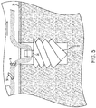
FIG. 3 is a schematic of a suture tape construct positioned in the bone of a subject prior to deployment; -
FIG. 4 is a schematic of a suture tape construct positioned in the bone of a subject after deployment; -
FIG. 5 is schematic of a suture tape construct used in connection with a threaded anchor prior to deployment; -
FIG. 6 is schematic of a suture tape construct used in connection with a threaded anchor after deployment; and -
FIG. 7 is a schematic of an alternative embodiment of a suture tape construct in an un-deployed configuration according to the present invention. - Referring now to the drawings, wherein like reference numerals refer to like parts throughout, there is seen in
FIG. 1 anon-sliding suture construct 10 comprising a length of fibrous filament (which can be suture tape) 12 having a pair ofprotrusions material 18 serving as a suture anchor is positioned alongfibrous filament 12, i.e.,fibrous filament 12 has been woven through braidedmaterial 18. For example,material 18 may be folded several times withfibrous filament 12 passing through each fold. In the depicted embodiment, braidedmaterial 18 has six punctures to receive suturefibrous filament 12; however, four punctures or eight punctures can be used (or any other number of punctures can be used as may be required for application of the non-sliding suture construct, as should be appreciated by a person of ordinary skill in the art in conjunction with a review of this disclosure). In accordance with an embodiment, flat braidedmaterial 18 may also be tubular (has a lumen). Further, in one embodiment, neithermaterial 18 norfibrous filament 12 has any knots, allowing free sliding of 18 over 12 (except for back overprotrusions -
Protrusions fibrous filament 12 so that the portion ofprotrusions fibrous filament 12 form barbs that are angled toward the free ends offibrous filament 12. Theprotrusions fibrous filament 12 or integrally with suturefibrous filament 12. In one embodiment where theprotrusions fibrous filament 12, suturefibrous filament 12 is woven over theprotrusion fibrous filament 12. In another embodiment, suturefibrous filament 12 is double backed into itself and exits itself to becomeprotrusions - As stated above,
protrusions fibrous filament 12.Protrusions material 18 to pass thereover in a single direction, i.e.,material 18 is free to transition from an extended un-deployed configuration as seen inFIG. 1 to a deployed configuration as seen inFIG. 2 by sliding overprotrusions protrusions fibrous filament 12 and braidedmaterial 18 prevents braidedmaterial 18 from sliding overprotrusions material 18 is in the deployed configuration ofFIG. 2 . - Referring briefly to
FIG. 7 , there is seen an alternative embodiment ofsuture tape construct 10 in an un-deployed configuration. In the depicted embodiment,braided material 18 comprises a lumen extending through a portion ofbraided material 18 betweenprotrusions fibrous filament 12 is not only woven through braidedmaterial 18, but is also extended through the lumen portion. - The configuration of
suture construct 10 illustrated inFIG. 2 provides an all-suture anchor that, when deployed inside a hole formed in a bone, may be used for a soft tissue to bone repair procedure, such as a double rotator cuff repair.Suture construct 10 may be deployed into a hole formed in bone with an installation device, such as that shown inFIG. 5 ofU.S. Patent Publication No. 2012/0290004 , which is incorporated herein by reference along with the related description in its entirety. Once braidedmaterial 18 has been shifted in the deployed configuration ofFIG. 2 ,protrusions 14 prevent any further movement ofmaterial 18 relative tofibrous filament 12, thereby providing a non-sliding arrangement wherefibrous filament 12 is fixed relative tomaterial 18. Additionally, in the deployed configuration, braidedmaterial 12 betweenprotrusions FIG. 6 ofU.S. Patent Publication No. 2012/0290004 , which is incorporated herein by reference along with the related description in its entirety. - Referring to
FIG. 3 , suture construct 10 with braidedmaterial 18 is positioned into a hole formed inbone 20 in the extended configuration. When the ends offibrous filament 12 are pulled, braidedmaterial 18 will move to the deployed configuration ofFIG. 4 by passing overprotrusions protrusions protrusions material 18 but do not allow passage of braidedmaterial 18 relative to suturefibrous filament 12 in the opposite direction,protrusions fibrous filament 12 from sliding relative to the y-knot formed by braidedmaterial 18. As a result,suture construct 10 may be used for a soft tissue to bone repair procedure, such as a double rotator cuff repair.Suture construct 10 thus allows for a soft tissue to bone repair using suture tape without the need for additional steps to secure against sliding as the suture tape ofsuture construct 10 is non-sliding with respect to braidedmaterial 18 that acts as the suture anchor. - In an alternative embodiment, similar to
FIG. 3 , the ends of braidedmaterial 18 are distally positioned in the extended configuration, while the ends of suturefibrous filament 12 are proximally positioned. When the ends of braidedmaterial 18 are located closer to the bone wall, they stick to the bone wall when the ends of suturefibrous filament 12 are pulled upward. Resistance provided by the bone wall against the ends of braidedmaterial 12 causes the portion of braidedmaterial 18 betweenprotrusions - Referring to
FIG. 5 ,non-sliding suture construct 10 comprising a length of suturefibrous filament 12 and having a pair ofprotrusions anchor 22 having aneyelet 24. In this embodiment,anchor 22 is first positioned in abone 20, as seen inFIG. 5 , withprotrusions eyelet 24. Next, construct 10 is slid througheyelet 24 in one direction until one ofprotrusions eyelet 24, thereby capturingeyelet 24 betweenprotrusions FIG. 6 . - While embodiments of the present invention has been particularly shown and described with reference to certain exemplary embodiments, it will be understood by one skilled in the art that various changes in detail may be effected therein without departing from the spirit and scope of the invention as defined by claims that can be supported by the written description and drawings. Further, where exemplary embodiments are described with reference to a certain number of elements it will be understood that the exemplary embodiments can be practiced utilizing either less than or more than the certain number of elements.
- Important Aspects of the present invention are:
- [1] A fibrous filament construct, comprising:
- a first section of fibrous filament extending from a first end to a second end; and
- a pair of protrusions extending from intermediate portions of the first section and spaced apart from each other to capture a suture anchor therebetween.
- [2] The construct of [1], further comprising a second section woven about the first section between the first end and the second end and moveable from an un-deployed position where the second section extends beyond the pair of protrusions to a deployed position where the second section is captured between the pair of protrusions.
- [3] The construct of [1], wherein the fibrous filament is suture tape.
- [4] The construct of [2], wherein the second section is braided.
- [5] The construct of [2], wherein the second section is flat.
- [6] The construct of [2], wherein the protrusions comprise segments of suture woven into the fibrous filament of the first section and extending therefrom at an angle that only allows passage of the second section in one direction.
- [7] The construct of [2], wherein the thickness of the second section is greater in the deployed position as compared to the thickness of the second section in the un-deployed position.
- [8] The construct of [2], wherein the second section comprises a lumen and is tubular.
- [9] The construct of [8], wherein the lumen extends within the second section between the pair of protrusions.
- [10] The construct of [9], wherein a portion of the first section extends through the lumen of the second section.
- [11] The construct of [1], further comprising a threaded anchor having an eyelet through which the first section passes.
- [12] The construct of [11], wherein the first section is moveable from an un-deployed position where the eyelet is positioned along the first section outside of the pair of protrusions to a deployed position where the eyelet is captured between the pair of protrusions.
- [13] A method of anchoring tissue to bone, comprising the steps of:
- inserting a suture anchor into a hole in a bone; and
- deploying a suture tape construct comprised of a first section of suture tape extending from a first end to a second end and a pair of protrusions extending from intermediate portions of the first section and spaced apart from each other so that the suture anchor is captured between the pair of protrusions.
- [14] The method of [13], wherein the suture anchor comprises a second section woven about the first section between the first end and the second end.
- [15] The method of [14], wherein the step of deploying the suture tape construct comprises pulling the first and second ends of the first section until the suture anchor is captured between the pair of protrusions.
- [16] The method of [14], wherein the second section is braided.
- [17] The method of [14], wherein the second section comprises a lumen extending therethrough between the pair of protrusions.
- [18] The method of [17], wherein a portion of the first section extends through the lumen of the second section.
- [19] The method of [13], wherein the suture anchor comprises a threaded anchor having an eyelet through which the first section passes.
- [20] The method of [19], wherein the step of deploying the suture tape construct comprises pulling one of the first and second ends of the first section until the eyelet of the suture anchor is captured between the pair of protrusions.
Claims (6)
- A fibrous filament and anchor construct (10), comprising:a first section (12) of fibrous filament extending from a first end to a second end;a pair of protrusions (14, 16) extending from intermediate portions of the first section (12) and spaced apart from each other;a second section comprising an anchor (22) comprising a proximal portion (24) and a distal portion, the anchor (22) being moveable from an undeployed position and configuraton to a deployed position and configuration, wherein the proximal portion (24) is configured to be captured between the pair of protrusions (14, 16) and the distal portion is configured to be fixed in a bone hole in the deployed position and configuration.
- The construct (10) of claim 1, wherein the fibrous filament is suture tape.
- The construct (10) of claim 1, wherein the distal portion of the anchor (22) is threaded.
- The construct (10) of claim 1, wherein the proximal portion (24) of the anchor (22) is an eyelet.
- The construct (10) of claim 1, wherein the protrusions (14, 16) comprise segments of suture woven into the fibrous filament of the first section (12) and extending therefrom at an angle that only allows passage of the second section (18) in one direction.
- The construct (10) of claim 1, wherein each respective protrusion (14, 16) is configured to be bent toward the other respective protrusion in the deployed position and configuration.
Applications Claiming Priority (3)
| Application Number | Priority Date | Filing Date | Title |
|---|---|---|---|
| US201562271401P | 2015-12-28 | 2015-12-28 | |
| PCT/US2016/068664 WO2017117100A1 (en) | 2015-12-28 | 2016-12-27 | Suture tape construct for providing anchor with non-sliding suture tape |
| EP16826611.2A EP3397174B1 (en) | 2015-12-28 | 2016-12-27 | Suture tape construct for providing anchor with non-sliding suture tape |
Related Parent Applications (1)
| Application Number | Title | Priority Date | Filing Date |
|---|---|---|---|
| EP16826611.2A Division EP3397174B1 (en) | 2015-12-28 | 2016-12-27 | Suture tape construct for providing anchor with non-sliding suture tape |
Publications (2)
| Publication Number | Publication Date |
|---|---|
| EP3692928A1 true EP3692928A1 (en) | 2020-08-12 |
| EP3692928B1 EP3692928B1 (en) | 2022-06-22 |
Family
ID=57799886
Family Applications (2)
| Application Number | Title | Priority Date | Filing Date |
|---|---|---|---|
| EP16826611.2A Active EP3397174B1 (en) | 2015-12-28 | 2016-12-27 | Suture tape construct for providing anchor with non-sliding suture tape |
| EP20166063.6A Active EP3692928B1 (en) | 2015-12-28 | 2016-12-27 | Suture tape construct for providing anchor with non-sliding suture tape |
Family Applications Before (1)
| Application Number | Title | Priority Date | Filing Date |
|---|---|---|---|
| EP16826611.2A Active EP3397174B1 (en) | 2015-12-28 | 2016-12-27 | Suture tape construct for providing anchor with non-sliding suture tape |
Country Status (9)
| Country | Link |
|---|---|
| US (2) | US10863978B2 (en) |
| EP (2) | EP3397174B1 (en) |
| JP (1) | JP7089472B2 (en) |
| KR (2) | KR102204150B1 (en) |
| CN (1) | CN108430340B (en) |
| AU (1) | AU2016381442B2 (en) |
| CA (2) | CA3010005C (en) |
| ES (2) | ES2923202T3 (en) |
| WO (1) | WO2017117100A1 (en) |
Families Citing this family (15)
| Publication number | Priority date | Publication date | Assignee | Title |
|---|---|---|---|---|
| WO2012151592A2 (en) * | 2011-05-05 | 2012-11-08 | Linvatec Corporation | Soft anchor made from suture filament and suture tape |
| CN116942244A (en) | 2017-07-24 | 2023-10-27 | 康曼德公司 | Self drilling anchor inserter system |
| EP3664719A1 (en) * | 2017-08-10 | 2020-06-17 | ConMed Corporation | Hybrid suture anchor |
| US20190380693A1 (en) * | 2018-06-18 | 2019-12-19 | Arthrex, Inc. | Flat surgical suture constructs with loops and methods of tissue fixation |
| US10849616B2 (en) | 2018-09-25 | 2020-12-01 | Arthrex, Inc. | Reinforced graft constructs and methods of tissue repairs |
| CN119405368A (en) | 2018-12-18 | 2025-02-11 | 康曼德公司 | Anchor inserters and anchor inserter systems |
| CN110368048A (en) * | 2019-07-04 | 2019-10-25 | 北京德益达美医疗科技有限公司 | All fronts holdfast |
| CN110353749A (en) * | 2019-07-10 | 2019-10-22 | 北京德益达美医疗科技有限公司 | All fronts holdfast |
| CN115397338B (en) * | 2020-05-06 | 2026-04-10 | 史密夫和内修有限公司 | Suture anchor insertion assembly and usage method |
| US11666323B1 (en) * | 2020-08-27 | 2023-06-06 | Riverpoint Medical, Llc | Soft anchors having increased engagement between deployment sutures and sleeve |
| US12279945B2 (en) | 2020-10-30 | 2025-04-22 | Ins Ortho, Inc. | Dynamic ligament repair device |
| US12458340B2 (en) * | 2022-04-24 | 2025-11-04 | LMD Innovations, LLC | Tapetak and methods of anchoring soft tissue to bone |
| KR102439443B1 (en) * | 2022-08-03 | 2022-09-05 | 아주약품(주) | Method for manufacturing suture anchor and manufactured suture anchor |
| WO2024089532A1 (en) * | 2022-10-24 | 2024-05-02 | DePuy Synthes Products, Inc. | Suture-based repair |
| JP2026505621A (en) * | 2023-02-18 | 2026-02-16 | アイエヌエス オルソ,インク. | Self-cinching adjustable loop suture construct |
Citations (3)
| Publication number | Priority date | Publication date | Assignee | Title |
|---|---|---|---|---|
| US20120101526A1 (en) * | 2010-10-26 | 2012-04-26 | Bennett William F | Surgical Suture System |
| US20120290004A1 (en) | 2011-05-06 | 2012-11-15 | Linvatec Corporation | Soft anchor made from suture filament and suture tape |
| WO2014164605A1 (en) * | 2013-03-12 | 2014-10-09 | Ziptek LLC. | Apparatus and method for securing tissue |
Family Cites Families (15)
| Publication number | Priority date | Publication date | Assignee | Title |
|---|---|---|---|---|
| US5540703A (en) | 1993-01-06 | 1996-07-30 | Smith & Nephew Richards Inc. | Knotted cable attachment apparatus formed of braided polymeric fibers |
| US5769894A (en) | 1997-02-05 | 1998-06-23 | Smith & Nephew, Inc. | Graft attachment device and method of attachment |
| US6773450B2 (en) * | 2002-08-09 | 2004-08-10 | Quill Medical, Inc. | Suture anchor and method |
| EA007116B1 (en) * | 2002-08-23 | 2006-06-30 | Квинно Сентр Пти Лтд. | Anchoring device and its implementation |
| US8100940B2 (en) * | 2002-09-30 | 2012-01-24 | Quill Medical, Inc. | Barb configurations for barbed sutures |
| US20090105826A1 (en) * | 2005-06-03 | 2009-04-23 | Mcleod Alan | Surgical Implants |
| EP2501300B1 (en) * | 2009-11-16 | 2018-07-11 | Ethicon LLC | Braided self-retaining sutures and methods |
| US9398943B2 (en) * | 2009-11-30 | 2016-07-26 | Covidien Lp | Ventral hernia repair with barbed suture |
| EP2404557A1 (en) * | 2010-07-06 | 2012-01-11 | Tornier, Inc. | Barbed scaffolds |
| EP2663240B1 (en) * | 2011-01-14 | 2017-03-22 | Synthes GmbH | Insertion instrument for anchor assembly |
| US8795334B2 (en) | 2011-01-28 | 2014-08-05 | Smith & Nephew, Inc. | Tissue repair |
| US9084597B2 (en) * | 2012-03-09 | 2015-07-21 | Smith & Nephew, Inc. | Suture-based knotless repair |
| US10016192B2 (en) | 2013-06-14 | 2018-07-10 | Tornier, Inc. | Suture for connecting a human or animal tissue, soft anchor and method for attaching a tissue to a bone |
| KR20150045280A (en) * | 2013-10-18 | 2015-04-28 | 한용갑 | Suture thread |
| US9888997B2 (en) * | 2015-07-20 | 2018-02-13 | Arthrex, Inc. | Soft anchor assembly with barbed flexible strand and techniques for use |
-
2016
- 2016-12-27 KR KR1020187018652A patent/KR102204150B1/en active Active
- 2016-12-27 CA CA3010005A patent/CA3010005C/en active Active
- 2016-12-27 EP EP16826611.2A patent/EP3397174B1/en active Active
- 2016-12-27 ES ES20166063T patent/ES2923202T3/en active Active
- 2016-12-27 EP EP20166063.6A patent/EP3692928B1/en active Active
- 2016-12-27 AU AU2016381442A patent/AU2016381442B2/en active Active
- 2016-12-27 ES ES16826611T patent/ES2796365T3/en active Active
- 2016-12-27 CN CN201680076624.9A patent/CN108430340B/en active Active
- 2016-12-27 JP JP2018534166A patent/JP7089472B2/en active Active
- 2016-12-27 CA CA3158855A patent/CA3158855A1/en active Pending
- 2016-12-27 US US15/390,969 patent/US10863978B2/en active Active
- 2016-12-27 WO PCT/US2016/068664 patent/WO2017117100A1/en not_active Ceased
- 2016-12-27 KR KR1020217000849A patent/KR102271609B1/en active Active
-
2020
- 2020-11-18 US US16/951,634 patent/US20210068808A1/en not_active Abandoned
Patent Citations (3)
| Publication number | Priority date | Publication date | Assignee | Title |
|---|---|---|---|---|
| US20120101526A1 (en) * | 2010-10-26 | 2012-04-26 | Bennett William F | Surgical Suture System |
| US20120290004A1 (en) | 2011-05-06 | 2012-11-15 | Linvatec Corporation | Soft anchor made from suture filament and suture tape |
| WO2014164605A1 (en) * | 2013-03-12 | 2014-10-09 | Ziptek LLC. | Apparatus and method for securing tissue |
Also Published As
| Publication number | Publication date |
|---|---|
| CA3010005A1 (en) | 2017-07-06 |
| KR102204150B1 (en) | 2021-01-19 |
| CA3158855A1 (en) | 2017-07-06 |
| AU2016381442A1 (en) | 2018-07-12 |
| AU2016381442B2 (en) | 2019-08-01 |
| US20210068808A1 (en) | 2021-03-11 |
| ES2796365T3 (en) | 2020-11-26 |
| EP3397174A1 (en) | 2018-11-07 |
| US20170181739A1 (en) | 2017-06-29 |
| KR102271609B1 (en) | 2021-07-02 |
| ES2923202T3 (en) | 2022-09-26 |
| KR20180090320A (en) | 2018-08-10 |
| WO2017117100A1 (en) | 2017-07-06 |
| EP3397174B1 (en) | 2020-04-08 |
| CN108430340A (en) | 2018-08-21 |
| EP3692928B1 (en) | 2022-06-22 |
| JP2019502463A (en) | 2019-01-31 |
| JP7089472B2 (en) | 2022-06-22 |
| KR20210007047A (en) | 2021-01-19 |
| CN108430340B (en) | 2021-03-09 |
| US10863978B2 (en) | 2020-12-15 |
| CA3010005C (en) | 2022-08-16 |
Similar Documents
| Publication | Publication Date | Title |
|---|---|---|
| EP3397174B1 (en) | Suture tape construct for providing anchor with non-sliding suture tape | |
| AU2018203869B2 (en) | Suture leader | |
| AU2017313744B2 (en) | Device for securing suture to an anchor body of a suture anchor | |
| US20200337697A1 (en) | Knotless soft tissue devices and techniques | |
| US20140039551A1 (en) | Suture Anchor Device and Methods of Use | |
| CN109077762B (en) | Fingerstall for collapsed suture loops | |
| US20140052177A1 (en) | Method and apparatus for attaching soft tissue to bone | |
| US11911019B2 (en) | All-suture anchor | |
| US12011155B2 (en) | Double row collapsible suture construct |
Legal Events
| Date | Code | Title | Description |
|---|---|---|---|
| PUAI | Public reference made under article 153(3) epc to a published international application that has entered the european phase |
Free format text: ORIGINAL CODE: 0009012 |
|
| STAA | Information on the status of an ep patent application or granted ep patent |
Free format text: STATUS: REQUEST FOR EXAMINATION WAS MADE |
|
| 17P | Request for examination filed |
Effective date: 20200331 |
|
| AC | Divisional application: reference to earlier application |
Ref document number: 3397174 Country of ref document: EP Kind code of ref document: P |
|
| AK | Designated contracting states |
Kind code of ref document: A1 Designated state(s): AL AT BE BG CH CY CZ DE DK EE ES FI FR GB GR HR HU IE IS IT LI LT LU LV MC MK MT NL NO PL PT RO RS SE SI SK SM TR |
|
| GRAP | Despatch of communication of intention to grant a patent |
Free format text: ORIGINAL CODE: EPIDOSNIGR1 |
|
| STAA | Information on the status of an ep patent application or granted ep patent |
Free format text: STATUS: GRANT OF PATENT IS INTENDED |
|
| INTG | Intention to grant announced |
Effective date: 20220110 |
|
| RIN1 | Information on inventor provided before grant (corrected) |
Inventor name: BRESLICH, GRADY |
|
| GRAS | Grant fee paid |
Free format text: ORIGINAL CODE: EPIDOSNIGR3 |
|
| GRAA | (expected) grant |
Free format text: ORIGINAL CODE: 0009210 |
|
| STAA | Information on the status of an ep patent application or granted ep patent |
Free format text: STATUS: THE PATENT HAS BEEN GRANTED |
|
| AC | Divisional application: reference to earlier application |
Ref document number: 3397174 Country of ref document: EP Kind code of ref document: P |
|
| AK | Designated contracting states |
Kind code of ref document: B1 Designated state(s): AL AT BE BG CH CY CZ DE DK EE ES FI FR GB GR HR HU IE IS IT LI LT LU LV MC MK MT NL NO PL PT RO RS SE SI SK SM TR |
|
| REG | Reference to a national code |
Ref country code: GB Ref legal event code: FG4D |
|
| REG | Reference to a national code |
Ref country code: CH Ref legal event code: EP |
|
| REG | Reference to a national code |
Ref country code: DE Ref legal event code: R096 Ref document number: 602016073101 Country of ref document: DE |
|
| REG | Reference to a national code |
Ref country code: AT Ref legal event code: REF Ref document number: 1499264 Country of ref document: AT Kind code of ref document: T Effective date: 20220715 |
|
| REG | Reference to a national code |
Ref country code: IE Ref legal event code: FG4D |
|
| REG | Reference to a national code |
Ref country code: ES Ref legal event code: FG2A Ref document number: 2923202 Country of ref document: ES Kind code of ref document: T3 Effective date: 20220926 |
|
| REG | Reference to a national code |
Ref country code: LT Ref legal event code: MG9D |
|
| REG | Reference to a national code |
Ref country code: NL Ref legal event code: MP Effective date: 20220622 |
|
| PG25 | Lapsed in a contracting state [announced via postgrant information from national office to epo] |
Ref country code: SE Free format text: LAPSE BECAUSE OF FAILURE TO SUBMIT A TRANSLATION OF THE DESCRIPTION OR TO PAY THE FEE WITHIN THE PRESCRIBED TIME-LIMIT Effective date: 20220622 Ref country code: NO Free format text: LAPSE BECAUSE OF FAILURE TO SUBMIT A TRANSLATION OF THE DESCRIPTION OR TO PAY THE FEE WITHIN THE PRESCRIBED TIME-LIMIT Effective date: 20220922 Ref country code: LT Free format text: LAPSE BECAUSE OF FAILURE TO SUBMIT A TRANSLATION OF THE DESCRIPTION OR TO PAY THE FEE WITHIN THE PRESCRIBED TIME-LIMIT Effective date: 20220622 Ref country code: HR Free format text: LAPSE BECAUSE OF FAILURE TO SUBMIT A TRANSLATION OF THE DESCRIPTION OR TO PAY THE FEE WITHIN THE PRESCRIBED TIME-LIMIT Effective date: 20220622 Ref country code: GR Free format text: LAPSE BECAUSE OF FAILURE TO SUBMIT A TRANSLATION OF THE DESCRIPTION OR TO PAY THE FEE WITHIN THE PRESCRIBED TIME-LIMIT Effective date: 20220923 Ref country code: FI Free format text: LAPSE BECAUSE OF FAILURE TO SUBMIT A TRANSLATION OF THE DESCRIPTION OR TO PAY THE FEE WITHIN THE PRESCRIBED TIME-LIMIT Effective date: 20220622 Ref country code: BG Free format text: LAPSE BECAUSE OF FAILURE TO SUBMIT A TRANSLATION OF THE DESCRIPTION OR TO PAY THE FEE WITHIN THE PRESCRIBED TIME-LIMIT Effective date: 20220922 |
|
| REG | Reference to a national code |
Ref country code: AT Ref legal event code: MK05 Ref document number: 1499264 Country of ref document: AT Kind code of ref document: T Effective date: 20220622 |
|
| PG25 | Lapsed in a contracting state [announced via postgrant information from national office to epo] |
Ref country code: RS Free format text: LAPSE BECAUSE OF FAILURE TO SUBMIT A TRANSLATION OF THE DESCRIPTION OR TO PAY THE FEE WITHIN THE PRESCRIBED TIME-LIMIT Effective date: 20220622 Ref country code: LV Free format text: LAPSE BECAUSE OF FAILURE TO SUBMIT A TRANSLATION OF THE DESCRIPTION OR TO PAY THE FEE WITHIN THE PRESCRIBED TIME-LIMIT Effective date: 20220622 |
|
| PG25 | Lapsed in a contracting state [announced via postgrant information from national office to epo] |
Ref country code: NL Free format text: LAPSE BECAUSE OF FAILURE TO SUBMIT A TRANSLATION OF THE DESCRIPTION OR TO PAY THE FEE WITHIN THE PRESCRIBED TIME-LIMIT Effective date: 20220622 |
|
| PG25 | Lapsed in a contracting state [announced via postgrant information from national office to epo] |
Ref country code: SM Free format text: LAPSE BECAUSE OF FAILURE TO SUBMIT A TRANSLATION OF THE DESCRIPTION OR TO PAY THE FEE WITHIN THE PRESCRIBED TIME-LIMIT Effective date: 20220622 Ref country code: SK Free format text: LAPSE BECAUSE OF FAILURE TO SUBMIT A TRANSLATION OF THE DESCRIPTION OR TO PAY THE FEE WITHIN THE PRESCRIBED TIME-LIMIT Effective date: 20220622 Ref country code: RO Free format text: LAPSE BECAUSE OF FAILURE TO SUBMIT A TRANSLATION OF THE DESCRIPTION OR TO PAY THE FEE WITHIN THE PRESCRIBED TIME-LIMIT Effective date: 20220622 Ref country code: PT Free format text: LAPSE BECAUSE OF FAILURE TO SUBMIT A TRANSLATION OF THE DESCRIPTION OR TO PAY THE FEE WITHIN THE PRESCRIBED TIME-LIMIT Effective date: 20221024 Ref country code: EE Free format text: LAPSE BECAUSE OF FAILURE TO SUBMIT A TRANSLATION OF THE DESCRIPTION OR TO PAY THE FEE WITHIN THE PRESCRIBED TIME-LIMIT Effective date: 20220622 Ref country code: CZ Free format text: LAPSE BECAUSE OF FAILURE TO SUBMIT A TRANSLATION OF THE DESCRIPTION OR TO PAY THE FEE WITHIN THE PRESCRIBED TIME-LIMIT Effective date: 20220622 Ref country code: AT Free format text: LAPSE BECAUSE OF FAILURE TO SUBMIT A TRANSLATION OF THE DESCRIPTION OR TO PAY THE FEE WITHIN THE PRESCRIBED TIME-LIMIT Effective date: 20220622 |
|
| PG25 | Lapsed in a contracting state [announced via postgrant information from national office to epo] |
Ref country code: PL Free format text: LAPSE BECAUSE OF FAILURE TO SUBMIT A TRANSLATION OF THE DESCRIPTION OR TO PAY THE FEE WITHIN THE PRESCRIBED TIME-LIMIT Effective date: 20220622 Ref country code: IS Free format text: LAPSE BECAUSE OF FAILURE TO SUBMIT A TRANSLATION OF THE DESCRIPTION OR TO PAY THE FEE WITHIN THE PRESCRIBED TIME-LIMIT Effective date: 20221022 |
|
| REG | Reference to a national code |
Ref country code: DE Ref legal event code: R097 Ref document number: 602016073101 Country of ref document: DE |
|
| PG25 | Lapsed in a contracting state [announced via postgrant information from national office to epo] |
Ref country code: AL Free format text: LAPSE BECAUSE OF FAILURE TO SUBMIT A TRANSLATION OF THE DESCRIPTION OR TO PAY THE FEE WITHIN THE PRESCRIBED TIME-LIMIT Effective date: 20220622 |
|
| PG25 | Lapsed in a contracting state [announced via postgrant information from national office to epo] |
Ref country code: DK Free format text: LAPSE BECAUSE OF FAILURE TO SUBMIT A TRANSLATION OF THE DESCRIPTION OR TO PAY THE FEE WITHIN THE PRESCRIBED TIME-LIMIT Effective date: 20220622 |
|
| PLBE | No opposition filed within time limit |
Free format text: ORIGINAL CODE: 0009261 |
|
| STAA | Information on the status of an ep patent application or granted ep patent |
Free format text: STATUS: NO OPPOSITION FILED WITHIN TIME LIMIT |
|
| 26N | No opposition filed |
Effective date: 20230323 |
|
| P01 | Opt-out of the competence of the unified patent court (upc) registered |
Effective date: 20230526 |
|
| REG | Reference to a national code |
Ref country code: CH Ref legal event code: PL |
|
| REG | Reference to a national code |
Ref country code: BE Ref legal event code: MM Effective date: 20221231 |
|
| PG25 | Lapsed in a contracting state [announced via postgrant information from national office to epo] |
Ref country code: SI Free format text: LAPSE BECAUSE OF FAILURE TO SUBMIT A TRANSLATION OF THE DESCRIPTION OR TO PAY THE FEE WITHIN THE PRESCRIBED TIME-LIMIT Effective date: 20220622 Ref country code: LU Free format text: LAPSE BECAUSE OF NON-PAYMENT OF DUE FEES Effective date: 20221227 |
|
| PG25 | Lapsed in a contracting state [announced via postgrant information from national office to epo] |
Ref country code: LI Free format text: LAPSE BECAUSE OF NON-PAYMENT OF DUE FEES Effective date: 20221231 Ref country code: IE Free format text: LAPSE BECAUSE OF NON-PAYMENT OF DUE FEES Effective date: 20221227 Ref country code: CH Free format text: LAPSE BECAUSE OF NON-PAYMENT OF DUE FEES Effective date: 20221231 |
|
| PG25 | Lapsed in a contracting state [announced via postgrant information from national office to epo] |
Ref country code: BE Free format text: LAPSE BECAUSE OF NON-PAYMENT OF DUE FEES Effective date: 20221231 |
|
| PG25 | Lapsed in a contracting state [announced via postgrant information from national office to epo] |
Ref country code: CY Free format text: LAPSE BECAUSE OF FAILURE TO SUBMIT A TRANSLATION OF THE DESCRIPTION OR TO PAY THE FEE WITHIN THE PRESCRIBED TIME-LIMIT Effective date: 20220622 |
|
| PG25 | Lapsed in a contracting state [announced via postgrant information from national office to epo] |
Ref country code: MK Free format text: LAPSE BECAUSE OF FAILURE TO SUBMIT A TRANSLATION OF THE DESCRIPTION OR TO PAY THE FEE WITHIN THE PRESCRIBED TIME-LIMIT Effective date: 20220622 Ref country code: HU Free format text: LAPSE BECAUSE OF FAILURE TO SUBMIT A TRANSLATION OF THE DESCRIPTION OR TO PAY THE FEE WITHIN THE PRESCRIBED TIME-LIMIT; INVALID AB INITIO Effective date: 20161227 |
|
| PG25 | Lapsed in a contracting state [announced via postgrant information from national office to epo] |
Ref country code: MC Free format text: LAPSE BECAUSE OF FAILURE TO SUBMIT A TRANSLATION OF THE DESCRIPTION OR TO PAY THE FEE WITHIN THE PRESCRIBED TIME-LIMIT Effective date: 20220622 |
|
| PG25 | Lapsed in a contracting state [announced via postgrant information from national office to epo] |
Ref country code: TR Free format text: LAPSE BECAUSE OF FAILURE TO SUBMIT A TRANSLATION OF THE DESCRIPTION OR TO PAY THE FEE WITHIN THE PRESCRIBED TIME-LIMIT Effective date: 20220622 Ref country code: MC Free format text: LAPSE BECAUSE OF FAILURE TO SUBMIT A TRANSLATION OF THE DESCRIPTION OR TO PAY THE FEE WITHIN THE PRESCRIBED TIME-LIMIT Effective date: 20220622 |
|
| PG25 | Lapsed in a contracting state [announced via postgrant information from national office to epo] |
Ref country code: MT Free format text: LAPSE BECAUSE OF FAILURE TO SUBMIT A TRANSLATION OF THE DESCRIPTION OR TO PAY THE FEE WITHIN THE PRESCRIBED TIME-LIMIT Effective date: 20220622 |
|
| PG25 | Lapsed in a contracting state [announced via postgrant information from national office to epo] |
Ref country code: BG Free format text: LAPSE BECAUSE OF FAILURE TO SUBMIT A TRANSLATION OF THE DESCRIPTION OR TO PAY THE FEE WITHIN THE PRESCRIBED TIME-LIMIT Effective date: 20220622 |
|
| PG25 | Lapsed in a contracting state [announced via postgrant information from national office to epo] |
Ref country code: BG Free format text: LAPSE BECAUSE OF FAILURE TO SUBMIT A TRANSLATION OF THE DESCRIPTION OR TO PAY THE FEE WITHIN THE PRESCRIBED TIME-LIMIT Effective date: 20220622 |
|
| PGFP | Annual fee paid to national office [announced via postgrant information from national office to epo] |
Ref country code: DE Payment date: 20251126 Year of fee payment: 10 |
|
| PGFP | Annual fee paid to national office [announced via postgrant information from national office to epo] |
Ref country code: GB Payment date: 20251120 Year of fee payment: 10 |
|
| PGFP | Annual fee paid to national office [announced via postgrant information from national office to epo] |
Ref country code: IT Payment date: 20251126 Year of fee payment: 10 |
|
| PGFP | Annual fee paid to national office [announced via postgrant information from national office to epo] |
Ref country code: FR Payment date: 20251124 Year of fee payment: 10 |
|
| PGFP | Annual fee paid to national office [announced via postgrant information from national office to epo] |
Ref country code: ES Payment date: 20260115 Year of fee payment: 10 |