EP3692859A1 - Sliding guide for container or shelf - Google Patents
Sliding guide for container or shelf Download PDFInfo
- Publication number
- EP3692859A1 EP3692859A1 EP19156304.8A EP19156304A EP3692859A1 EP 3692859 A1 EP3692859 A1 EP 3692859A1 EP 19156304 A EP19156304 A EP 19156304A EP 3692859 A1 EP3692859 A1 EP 3692859A1
- Authority
- EP
- European Patent Office
- Prior art keywords
- fixed
- movable portion
- shelf
- fixed portion
- bar
- Prior art date
- Legal status (The legal status is an assumption and is not a legal conclusion. Google has not performed a legal analysis and makes no representation as to the accuracy of the status listed.)
- Withdrawn
Links
- 230000000903 blocking effect Effects 0.000 claims description 8
- 239000006096 absorbing agent Substances 0.000 claims description 4
- 230000035939 shock Effects 0.000 claims description 4
- 238000000605 extraction Methods 0.000 description 3
- 238000003780 insertion Methods 0.000 description 2
- 230000008878 coupling Effects 0.000 description 1
- 238000010168 coupling process Methods 0.000 description 1
- 238000005859 coupling reaction Methods 0.000 description 1
- 238000005096 rolling process Methods 0.000 description 1
- 238000006467 substitution reaction Methods 0.000 description 1
- 230000007704 transition Effects 0.000 description 1
Images



Classifications
-
- A—HUMAN NECESSITIES
- A47—FURNITURE; DOMESTIC ARTICLES OR APPLIANCES; COFFEE MILLS; SPICE MILLS; SUCTION CLEANERS IN GENERAL
- A47B—TABLES; DESKS; OFFICE FURNITURE; CABINETS; DRAWERS; GENERAL DETAILS OF FURNITURE
- A47B88/00—Drawers for tables, cabinets or like furniture; Guides for drawers
- A47B88/40—Sliding drawers; Slides or guides therefor
- A47B88/41—Drawers with castors, rollers or wheels, supported directly on a surface below, e.g. on a floor, shelf or desktop
-
- A—HUMAN NECESSITIES
- A47—FURNITURE; DOMESTIC ARTICLES OR APPLIANCES; COFFEE MILLS; SPICE MILLS; SUCTION CLEANERS IN GENERAL
- A47B—TABLES; DESKS; OFFICE FURNITURE; CABINETS; DRAWERS; GENERAL DETAILS OF FURNITURE
- A47B88/00—Drawers for tables, cabinets or like furniture; Guides for drawers
- A47B88/40—Sliding drawers; Slides or guides therefor
- A47B88/483—Sliding drawers; Slides or guides therefor with single extensible guides or parts
- A47B88/487—Sliding drawers; Slides or guides therefor with single extensible guides or parts with rollers, ball bearings, wheels, or the like
Definitions
- the present invention relates to the technical sector of furniture accessories and in particular refers to a sliding guide for container or shelf.
- guides are used in pairs, since they are fixed to opposite sides of container or shelf in order to guarantee its sliding in a direction parallel to the longitudinal axis of the guides.
- a disadvantage of the known guides is that they must be fixed parallel and that they cannot be used, for example, to allow the sliding of "quarter" containers or shelves, i.e. those containers or shelves which are triangular shaped and that must be contained in a corner cabinet or between corner walls.
- the main object of the present invention is to propose a sliding guide for container or support or shelf allowing the support and the sliding of a container and/or of a support and/or of a plane of triangular shape and which must be extracted or inserted respectively in a corner cabinet or between two walls arranged at an angle.
- Another object is to propose a guide that allows the extraction and total re-insertion of container or shelf into relative furniture or corner niche.
- numeral 1 indicates a sliding guide intended to centrally support a container 2, commonly a drawer or a shelf for an angular piece of furniture 10.
- the sliding guide 1 is designed to sustain a shelf 30 sliding onto a mostly horizontal support 27 fixed between two walls 31 arranged at an angle.
- the sliding guide 1 consists of a fixed portion 3 and a movable portion 4, mutually combinable and sliding between a closed condition C, wherein the movable portion 4 is almost completely facing and superimposed on the fixed portion 3 and an opened condition A wherein the movable portion 4 is almost completely withdrawn from the fixed portion 3 and is marginally overlapped thereto.
- the fixed portion 3 is fixed to the support 27 arranged almost horizontally in the angular furniture 10 or fixed between the two corner walls 31.
- This fixed portion 3 comprises a longitudinal guide 8 on each of its sides a longitudinal support 6 is fixed.
- the longitudinal guide 8 is shaped like a rectangular section tubular having a longitudinal opening 28 and an external end 11 and an inner wall 22.
- a stop 9 is fixed outside the longitudinal guide 8 near its external end 11.
- the longitudinal support 6 has four first through holes 20 designed to be each engaged by a first fixing element 23, for example constituted by a screw, for locking itself to support 27.
- the movable portion 4 comprises a bar 15 with an inverted "T" shaped section having a longitudinal bracket 19 projecting laterally from the vertical wall or "T leg".
- the heads of the bar 15 are defined by an outer wall 25 and an inner wall 26.
- the vertical wall, "T leg”, of the bar 15 has third holes 32 designed to engage second fixing elements 24, for example constituted by screws or bolts, for locking the bar 15 to the drawer 2, in particular to its container bottom 18, or to the shelf 30.
- the movable portion 4 can also comprises a longitudinal plane, known and not illustrated, also provided with through holes which acts as a thickness interposed between the bar 15 and the container bottom 18 of drawer 2 or of shelf 30.
- the movable portion 4 further comprises a blocking means 14 constituted by a rod 29 which carries a pin 16 at an inner end and carries a handle 17 to the remaining external end.
- the sliding member 7 is interposed between the fixed portion 3 and the movable portion 4 for facilitating the mutual sliding.
- the sliding member 7 consist of a plurality of wheels, four of which are shown in figure 2 , which are rotatably supported by T bar 15 so allowing rolling friction of this latter 15 with respect the longitudinal guide 8 during the mutual sliding of fixed 3 and movable 4 portions.
- the sliding member 7 could likewise comprises rollers and/or balls and/or bearings, which are together or as substitutions of the wheels of figure 2 .
- the sliding member 7 is constituted by a plurality of wheels pivoted inside the longitudinal guide 8 so as to contact the side walls of the bar 15 so as to guide and facilitate its sliding inside the longitudinal guide 8.
- the sliding member 7 has rollers and/or balls and/or bearings together or in place of the wheels shown in Figure 7 .
- the sliding guide 1 provides that the movable portion 4 is coupled to the fixed portion 3 so as to slide between a closed condition C, wherein the movable portion 4 is almost completely facing to or laid upon the fixed portion 3 and the container 2 or the shelf 30 stand above the support 27, and an opened condition A in which the movable portion 4 is almost completely removed from the fixed portion 3, or are only marginally overlapped, and the container 2 or shelf 30 protrude from support 27.
- the head of the overturned T bar 15 is slidably inserted into the longitudinal guide 8 and the "T leg" or vertical wall of the bar 15 protrudes from the longitudinal opening 28.
- the blocking means 14, therefore the rod 29, is rotatably supported by the longitudinal bracket 19 and is interposed between the fixed portion 3 and the movable portion 4 to prevent its decoupling in the passage between the closed condition C and the opened condition A and vice versa.
- the release of movable portion 4 from fixed portion 3 is avoided because the handle 17 abuts the outer wall 25 of the bar 15 and the pin 16 abuts the inner wall 26 of the latter 15 until insisting into the stop 9 blocking the extraction of the movable portion 4 from the fixed portion 3.
- the handle 17 acts as a rotatable grip to allow the pin 16 to disengage from the inner wall 26 of the bar 15 in correspondence with the transition from the opened condition A to a release condition S in which the bar 15 is removed completely from the longitudinal guide 8 and the movable portion 4 is thus uncoupled from the fixed portion 3.
- the handle 17 In the passage from the opened condition A to the closed condition C, the handle 17 is released so as to position itself almost perpendicularly in front of the head of the bar 15.
- a shock absorber 12 is fixed at the outer end of the fixed portion 3 from which its piston rod 33 protrudes to contact with compliance the container 2 or the shelf 30 near the end phase of the passage from the opened condition A to the closed condition C.
- shock absorber 12 between the fixed portion 3 and the movable portion 4, but with the latter 12 fixed to the movable portion 4 near the outer wall 25 of the bar 15, or of the inner wall 26 of the latter.
- shock absorber 12 is fixed to the furniture bottom or to corner wall bottom facing respectively the container 2 or the shelf 30 so that the piston rod 33 can contact with compliance the latter during the passage from the opening condition A to closing condition C.
- the main advantage of the present invention is to provide a sliding guide for container or shelf which allows the support and the sliding of a container and/or of a shelf and/or of a triangular shaped surface which must be extracted and inserted respectively in a corner furniture or between two walls arranged at an angle.
- Another advantage is to provide a guide allowing the complete extraction and re-insertion of the container or shelf from or into the relative furniture or corner niche.
Landscapes
- Drawers Of Furniture (AREA)
Abstract
A sliding guide for container (2) or shelf (30) consists of at least one fixed portion (3), which can be fixed to a support (27) arranged almost horizontally in a piece of furniture (10) or between two corner walls (31), and at least a movable portion (4) that can be fixed to the container (2) or to the shelf (30), with said fixed portion (3) and movable portion (4), mutually coupled and sliding between a closed condition (C), where the movable portion (4) is almost completely facing the fixed portion (3) and the container (2) is inside the furniture (10) or the shelf (30) is between the corner walls (31), and an open condition (A) in which the movable portion (4) is almost completely withdrawn from the fixed portion (3) and the container (2) is extracted from the furniture (10) or the shelf (30) is extracted from the recess defined by the angled walls (31).
The fixed portion (3) comprises a longitudinal guide (8) which is fixed to a longitudinal support (6). The movable portion (4) comprises a bar (15) slidingly inserted into the longitudinal guide (8) almost completely in the closed condition (C) and almost partially inserted in the opened condition (A).
A sliding member (7) is interposed between the fixed portion (3) and the movable portion (4) for facilitating the mutual sliding.
Description
- The present invention relates to the technical sector of furniture accessories and in particular refers to a sliding guide for container or shelf.
- There are known guides for containers, such as drawers and/or shelves and/or supports, which each have a portion that can be fixed to a piece of furniture, or a vertical wall, and a portion that can be fixed to the container or shelf and with these two portions that can be coupled together during use.
- Usually guides are used in pairs, since they are fixed to opposite sides of container or shelf in order to guarantee its sliding in a direction parallel to the longitudinal axis of the guides.
- A disadvantage of the known guides is that they must be fixed parallel and that they cannot be used, for example, to allow the sliding of "quarter" containers or shelves, i.e. those containers or shelves which are triangular shaped and that must be contained in a corner cabinet or between corner walls.
- The main object of the present invention is to propose a sliding guide for container or support or shelf allowing the support and the sliding of a container and/or of a support and/or of a plane of triangular shape and which must be extracted or inserted respectively in a corner cabinet or between two walls arranged at an angle.
- Another object is to propose a guide that allows the extraction and total re-insertion of container or shelf into relative furniture or corner niche.
- The characteristics of the invention are shown below with particular reference to the attached drawings in which:
-
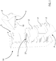
Figure 1 shows a perspective view of an angle drawer unit equipped with drawers each supported by a sliding guide for container or support or shelf object of the present invention; -
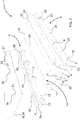
Figure 2 shows an exploded view of one of the sliding guide offigure 1 ; -
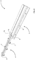
Figure 3 shows a perspective view of the guide offigure 2 in a closed condition; -
Figure 4 shows a view of the guide offigure 3 in an opened condition; -
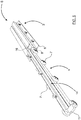
Figure 5 shows a view of the guide offigure 3 in a release condition; -
Figure 6 shows a perspective view of a support or shelf arranged between corner walls and slidably supported by a sliding guide object of the present invention; -
Figure 7 shows a second embodiment of the sliding guide object of the present invention, having removed parts for better highlighting other parts. - With reference to
Figures 1-5 ,numeral 1 indicates a sliding guide intended to centrally support acontainer 2, commonly a drawer or a shelf for an angular piece offurniture 10. - In
Figure 6 , thesliding guide 1 is designed to sustain ashelf 30 sliding onto a mostlyhorizontal support 27 fixed between twowalls 31 arranged at an angle. - The
sliding guide 1 consists of a fixedportion 3 and amovable portion 4, mutually combinable and sliding between a closed condition C, wherein themovable portion 4 is almost completely facing and superimposed on thefixed portion 3 and an opened condition A wherein themovable portion 4 is almost completely withdrawn from thefixed portion 3 and is marginally overlapped thereto. - The
fixed portion 3 is fixed to thesupport 27 arranged almost horizontally in theangular furniture 10 or fixed between the twocorner walls 31. - This
fixed portion 3 comprises alongitudinal guide 8 on each of its sides alongitudinal support 6 is fixed. - The
longitudinal guide 8 is shaped like a rectangular section tubular having alongitudinal opening 28 and anexternal end 11 and aninner wall 22. - A
stop 9 is fixed outside thelongitudinal guide 8 near itsexternal end 11. - The
longitudinal support 6 has four first throughholes 20 designed to be each engaged by afirst fixing element 23, for example constituted by a screw, for locking itself to support 27. - The
movable portion 4 comprises abar 15 with an inverted "T" shaped section having alongitudinal bracket 19 projecting laterally from the vertical wall or "T leg". The heads of thebar 15 are defined by anouter wall 25 and aninner wall 26. - The vertical wall, "T leg", of the
bar 15 hasthird holes 32 designed to engagesecond fixing elements 24, for example constituted by screws or bolts, for locking thebar 15 to thedrawer 2, in particular to itscontainer bottom 18, or to theshelf 30. - The
movable portion 4 can also comprises a longitudinal plane, known and not illustrated, also provided with through holes which acts as a thickness interposed between thebar 15 and thecontainer bottom 18 ofdrawer 2 or ofshelf 30. - The
movable portion 4 further comprises ablocking means 14 constituted by arod 29 which carries apin 16 at an inner end and carries ahandle 17 to the remaining external end. - The sliding
member 7 is interposed between the fixedportion 3 and themovable portion 4 for facilitating the mutual sliding. - In the preferred embodiment of
figure 2 , the slidingmember 7 consist of a plurality of wheels, four of which are shown infigure 2 , which are rotatably supported byT bar 15 so allowing rolling friction of this latter 15 with respect thelongitudinal guide 8 during the mutual sliding of fixed 3 and movable 4 portions. - In variants not illustrated but equivalent, the sliding
member 7 could likewise comprises rollers and/or balls and/or bearings, which are together or as substitutions of the wheels offigure 2 . - In a second embodiment shown in
Figure 7 , the slidingmember 7 is constituted by a plurality of wheels pivoted inside thelongitudinal guide 8 so as to contact the side walls of thebar 15 so as to guide and facilitate its sliding inside thelongitudinal guide 8. - In variants not shown but equivalent of the second embodiment, the sliding
member 7 has rollers and/or balls and/or bearings together or in place of the wheels shown inFigure 7 . - During usage, the
sliding guide 1 provides that themovable portion 4 is coupled to thefixed portion 3 so as to slide between a closed condition C, wherein themovable portion 4 is almost completely facing to or laid upon thefixed portion 3 and thecontainer 2 or theshelf 30 stand above thesupport 27, and an opened condition A in which themovable portion 4 is almost completely removed from thefixed portion 3, or are only marginally overlapped, and thecontainer 2 orshelf 30 protrude fromsupport 27. - When the
guide 1 is assembled, the head of theoverturned T bar 15 is slidably inserted into thelongitudinal guide 8 and the "T leg" or vertical wall of thebar 15 protrudes from thelongitudinal opening 28. - The blocking means 14, therefore the
rod 29, is rotatably supported by thelongitudinal bracket 19 and is interposed between the fixedportion 3 and themovable portion 4 to prevent its decoupling in the passage between the closed condition C and the opened condition A and vice versa. During this step the release ofmovable portion 4 from fixedportion 3 is avoided because thehandle 17 abuts theouter wall 25 of thebar 15 and thepin 16 abuts theinner wall 26 of the latter 15 until insisting into thestop 9 blocking the extraction of themovable portion 4 from thefixed portion 3. - With reference to
Figure 5 , thehandle 17 acts as a rotatable grip to allow thepin 16 to disengage from theinner wall 26 of thebar 15 in correspondence with the transition from the opened condition A to a release condition S in which thebar 15 is removed completely from thelongitudinal guide 8 and themovable portion 4 is thus uncoupled from the fixedportion 3. - The coupling between the two portions, movable 4 and fixed 3, occurs simply by inserting the head of the
bar 15 into thelongitudinal guide 8 and the "T leg" or vertical wall into theopening 28 while thepin 16 is kept raised by thestop 9, so avoiding interference, by means of the proper rotation ofhandle 17. - In the passage from the opened condition A to the closed condition C, the
handle 17 is released so as to position itself almost perpendicularly in front of the head of thebar 15. - A
shock absorber 12 is fixed at the outer end of the fixedportion 3 from which itspiston rod 33 protrudes to contact with compliance thecontainer 2 or theshelf 30 near the end phase of the passage from the opened condition A to the closed condition C. - To these two preferred embodiments it is possible to associate other equivalent forms, not shown, always providing the interposition of shock absorber 12 between the
fixed portion 3 and themovable portion 4, but with the latter 12 fixed to themovable portion 4 near theouter wall 25 of thebar 15, or of theinner wall 26 of the latter. - A variant not shown provides that the
shock absorber 12 is fixed to the furniture bottom or to corner wall bottom facing respectively thecontainer 2 or theshelf 30 so that thepiston rod 33 can contact with compliance the latter during the passage from the opening condition A to closing condition C. - The main advantage of the present invention is to provide a sliding guide for container or shelf which allows the support and the sliding of a container and/or of a shelf and/or of a triangular shaped surface which must be extracted and inserted respectively in a corner furniture or between two walls arranged at an angle.
- Another advantage is to provide a guide allowing the complete extraction and re-insertion of the container or shelf from or into the relative furniture or corner niche.
Claims (10)
- Sliding guide for container (2) or shelf (30) consisting of at least one fixed portion (3), which can be fixed to a support (27) arranged almost horizontally in a furniture (10) or between two corner walls (31), and at least a movable portion (4) that can be fixed to the container (2) or to the shelf (30), with said fixed portion (3) and movable portion (4), mutually coupled and sliding between a closed condition (C), wherein the movable portion (4) is almost completely facing the fixed portion (3) and the container (2) or the shelf (30) overhang the support (27), and an opened condition (A) in which the movable portion (4) is almost completely withdrawn from the fixed portion (3) and the container (2) or the shelf (30) protrude from the support (27); said guide (1) being characterized in that :- the fixed portion (3) comprises at least a longitudinal guide (8) fixed to at least a longitudinal support (6);- the movable portion (4) comprises at least a bar (15) slidingly inserted into the longitudinal guide (8) almost completely at closed condition (C) and almost partially at opened condition (A);- at least a sliding member (7) is interposed between the fixed portion (3) and the movable portion (4) to facilitate the mutual sliding.
- Guide according to claim 1 characterized in that :- the fixed portion (3) further comprises a stop (9) fixed outside the longitudinal guide (8) near an external end (11);- the movable portion (4) further comprises a blocking means (14), longitudinally supported by the bar (15), and provided with a pin (16) at an inner end thereof and the remaining external end of the blocking means (14) is provided with a handle (17);- said blocking means (14) being interposed between the fixed portion (3) and the movable portion (4) to prevent its decoupling during the passage between the closed condition (C) and the opened condition (A) and vice versa.
- Guide according to claim 2 characterized in that , passing from the closed condition (C) to the open condition (A), the handle (17) always abuts the outer wall (25) of the bar (15) and the pin (16) always abuts the inner wall (26) of the bar (15) until abutting the stop (9) of the fixed portion (3), avoiding the release of the movable portion (4) from the fixed portion (3).
- Guide according to claim 3 or claim 4, characterized in that the handle (17) acts as a rotatable grip for disengaging the pin (16) both from the inner wall (26) of the bar (15) and from the stop (9) of the fixed portion (3) during the passage from the opened condition (A) to the release condition (S) in which the movable portion (4) is released from the fixed portion (3).
- Guide according to any of the previous claims 2-4, characterized in that the bar (15) carries a longitudinal bracket (19) for housing the blocking means (14).
- Guide according to any of the previous claims, characterized in that the at least one sliding member (7) comprises at least one of roller and/or wheel and/or ball and/or bearing carried by at least a side of the bar (15).
- Guide according to any of the previous claims, characterized in that the at least one sliding member (7) comprises at least one of roller and/or wheel and/or ball and/or bearing housed inside the longitudinal guide (8).
- Guide according to any of the previous claims, characterized in that at least the longitudinal support (6) is provided with at least a first hole (20) intended to be engaged by at least a first fixing element (23) of the movable portion (4) to the support (27).
- Guide according to any of the previous claims, characterized in that the bar (15) is provided with at least a third hole (32) designed to be engaged by at least one second fixing element (24) for blocking the bar (15) to the drawer (2) or to the shelf (30).
- Guide according to any of the previous claims, characterized in that between the fixed portion (3) and the movable portion (4) a shock absorber (12) is interposed to softly dampen the speed of the drawer (2) or of the shelf (30) in the passage from the opened condition (A) to the closed condition (C).
Priority Applications (1)
| Application Number | Priority Date | Filing Date | Title |
|---|---|---|---|
| EP19156304.8A EP3692859A1 (en) | 2019-02-08 | 2019-02-08 | Sliding guide for container or shelf |
Applications Claiming Priority (1)
| Application Number | Priority Date | Filing Date | Title |
|---|---|---|---|
| EP19156304.8A EP3692859A1 (en) | 2019-02-08 | 2019-02-08 | Sliding guide for container or shelf |
Publications (1)
| Publication Number | Publication Date |
|---|---|
| EP3692859A1 true EP3692859A1 (en) | 2020-08-12 |
Family
ID=66685330
Family Applications (1)
| Application Number | Title | Priority Date | Filing Date |
|---|---|---|---|
| EP19156304.8A Withdrawn EP3692859A1 (en) | 2019-02-08 | 2019-02-08 | Sliding guide for container or shelf |
Country Status (1)
| Country | Link |
|---|---|
| EP (1) | EP3692859A1 (en) |
Citations (3)
| Publication number | Priority date | Publication date | Assignee | Title |
|---|---|---|---|---|
| US2074371A (en) * | 1935-09-09 | 1937-03-23 | Sheldon & Co E H | Drawer guide |
| US5813736A (en) * | 1996-09-12 | 1998-09-29 | Ballew; Ann | Cabinet storage device |
| EP1374735A1 (en) * | 2002-06-27 | 2004-01-02 | Westfalia Profiltechnik GmbH & Co. KG | Guide and runner system of drawers for tool wagons or such |
-
2019
- 2019-02-08 EP EP19156304.8A patent/EP3692859A1/en not_active Withdrawn
Patent Citations (3)
| Publication number | Priority date | Publication date | Assignee | Title |
|---|---|---|---|---|
| US2074371A (en) * | 1935-09-09 | 1937-03-23 | Sheldon & Co E H | Drawer guide |
| US5813736A (en) * | 1996-09-12 | 1998-09-29 | Ballew; Ann | Cabinet storage device |
| EP1374735A1 (en) * | 2002-06-27 | 2004-01-02 | Westfalia Profiltechnik GmbH & Co. KG | Guide and runner system of drawers for tool wagons or such |
Similar Documents
| Publication | Publication Date | Title |
|---|---|---|
| US20130270987A1 (en) | Freezer slide rack alignment | |
| US7997667B2 (en) | Rack and pinion refrigerator storage system | |
| US8141968B2 (en) | Support beam for a cabinet drawer | |
| US9872562B2 (en) | Cabinet | |
| US9894996B1 (en) | Cabinet | |
| US8777341B2 (en) | Sliding shelves for refrigerators and freezers | |
| US8668290B2 (en) | Rack and pinion refrigerator storage system | |
| US8328302B2 (en) | Refrigerator drawer and refrigerator having the same | |
| US7677125B2 (en) | Rack and pinion stabilizer system | |
| TW201900072A (en) | Guide system for guiding the door leaf | |
| US9433292B2 (en) | Alignment guide | |
| US20100065700A1 (en) | Lock for fixation device | |
| US10716397B2 (en) | Gun cabinet | |
| US9016813B2 (en) | Floating time bar | |
| CN113727627A (en) | Rotatable wall cabinet pull-out element | |
| CN106163330A (en) | Furniture or home appliances and for furniture or the engagement unit of home appliances | |
| US20190174919A1 (en) | Cabinet drawer | |
| KR101965980B1 (en) | shelf for mounting sliding Rail | |
| EP3692859A1 (en) | Sliding guide for container or shelf | |
| JP7311539B2 (en) | A furniture or appliance component and a method for attaching a functional unit of a drawer element to a furniture or appliance component | |
| KR102609376B1 (en) | Refrigerator | |
| WO2013041686A2 (en) | A cooling device wherein shelf height can be changed | |
| US12167792B2 (en) | Revolving shelf multi-shelf cabinet storage system | |
| EP2201862B1 (en) | Equipment for the partial and temporary extraction of a corner furniture chariot | |
| EP2415370B1 (en) | Cabinet with pull-out shelf provided with articulated arm and guide means. |
Legal Events
| Date | Code | Title | Description |
|---|---|---|---|
| PUAI | Public reference made under article 153(3) epc to a published international application that has entered the european phase |
Free format text: ORIGINAL CODE: 0009012 |
|
| STAA | Information on the status of an ep patent application or granted ep patent |
Free format text: STATUS: THE APPLICATION HAS BEEN PUBLISHED |
|
| AK | Designated contracting states |
Kind code of ref document: A1 Designated state(s): AL AT BE BG CH CY CZ DE DK EE ES FI FR GB GR HR HU IE IS IT LI LT LU LV MC MK MT NL NO PL PT RO RS SE SI SK SM TR |
|
| AX | Request for extension of the european patent |
Extension state: BA ME |
|
| 18W | Application withdrawn |
Effective date: 20210209 |