EP3692334B1 - Coordinate measuring machine probe identification apparatus and method - Google Patents
Coordinate measuring machine probe identification apparatus and method Download PDFInfo
- Publication number
- EP3692334B1 EP3692334B1 EP18795846.7A EP18795846A EP3692334B1 EP 3692334 B1 EP3692334 B1 EP 3692334B1 EP 18795846 A EP18795846 A EP 18795846A EP 3692334 B1 EP3692334 B1 EP 3692334B1
- Authority
- EP
- European Patent Office
- Prior art keywords
- probe
- indicia
- shaft
- stripe
- stripes
- Prior art date
- Legal status (The legal status is an assumption and is not a legal conclusion. Google has not performed a legal analysis and makes no representation as to the accuracy of the status listed.)
- Active
Links
Images



Classifications
-
- G—PHYSICS
- G01—MEASURING; TESTING
- G01B—MEASURING LENGTH, THICKNESS OR SIMILAR LINEAR DIMENSIONS; MEASURING ANGLES; MEASURING AREAS; MEASURING IRREGULARITIES OF SURFACES OR CONTOURS
- G01B5/00—Measuring arrangements characterised by the use of mechanical techniques
- G01B5/004—Measuring arrangements characterised by the use of mechanical techniques for measuring coordinates of points
- G01B5/008—Measuring arrangements characterised by the use of mechanical techniques for measuring coordinates of points using coordinate measuring machines
- G01B5/012—Contact-making feeler heads therefor
-
- G—PHYSICS
- G01—MEASURING; TESTING
- G01B—MEASURING LENGTH, THICKNESS OR SIMILAR LINEAR DIMENSIONS; MEASURING ANGLES; MEASURING AREAS; MEASURING IRREGULARITIES OF SURFACES OR CONTOURS
- G01B11/00—Measuring arrangements characterised by the use of optical techniques
- G01B11/002—Measuring arrangements characterised by the use of optical techniques for measuring two or more coordinates
- G01B11/005—Measuring arrangements characterised by the use of optical techniques for measuring two or more coordinates coordinate measuring machines
- G01B11/007—Measuring arrangements characterised by the use of optical techniques for measuring two or more coordinates coordinate measuring machines feeler heads therefor
-
- G—PHYSICS
- G01—MEASURING; TESTING
- G01B—MEASURING LENGTH, THICKNESS OR SIMILAR LINEAR DIMENSIONS; MEASURING ANGLES; MEASURING AREAS; MEASURING IRREGULARITIES OF SURFACES OR CONTOURS
- G01B21/00—Measuring arrangements or details thereof, where the measuring technique is not covered by the other groups of this subclass, unspecified or not relevant
- G01B21/02—Measuring arrangements or details thereof, where the measuring technique is not covered by the other groups of this subclass, unspecified or not relevant for measuring length, width, or thickness
- G01B21/04—Measuring arrangements or details thereof, where the measuring technique is not covered by the other groups of this subclass, unspecified or not relevant for measuring length, width, or thickness by measuring coordinates of points
- G01B21/047—Accessories, e.g. for positioning, for tool-setting, for measuring probes
-
- G—PHYSICS
- G01—MEASURING; TESTING
- G01B—MEASURING LENGTH, THICKNESS OR SIMILAR LINEAR DIMENSIONS; MEASURING ANGLES; MEASURING AREAS; MEASURING IRREGULARITIES OF SURFACES OR CONTOURS
- G01B7/00—Measuring arrangements characterised by the use of electric or magnetic techniques
- G01B7/004—Measuring arrangements characterised by the use of electric or magnetic techniques for measuring coordinates of points
- G01B7/008—Measuring arrangements characterised by the use of electric or magnetic techniques for measuring coordinates of points using coordinate measuring machines
- G01B7/012—Contact-making feeler heads therefor
-
- G—PHYSICS
- G01—MEASURING; TESTING
- G01B—MEASURING LENGTH, THICKNESS OR SIMILAR LINEAR DIMENSIONS; MEASURING ANGLES; MEASURING AREAS; MEASURING IRREGULARITIES OF SURFACES OR CONTOURS
- G01B2210/00—Aspects not specifically covered by any group under G01B, e.g. of wheel alignment, caliper-like sensors
- G01B2210/60—Unique sensor identification
Definitions
- Various embodiments of the invention relate to identifying probes for use with coordinate measurement machines.
- CMMs Coordinate measuring machines
- CMMs can measure critical dimensions of aircraft engine components, surgical tools, and gun barrels. Precise and accurate measurements help ensure that their underlying systems, such as an aircraft in the case of aircraft components, operate as specified.
- CMMs often use one or more tactile or optical probes to measure an object. Proper identification of the correct probe can be critical to accurate measurement.
- a probe for coupling with a movable portion of a coordinate measuring machine is defined according to claim 1.
- a method of identifying a probe is defined according to claim 7.
- Figures 2 to 5 and 8 show embodiments of the present invention.
- Figures la, lb, 6 and 7 show further examples which are not encompassed in the scope of the invention, even if they are named “embodiments" in the corresponding parts of the description. The scope of protection is defined by the claims.
- a coordinate measuring machine probe has indicia identifying it on its exterior surface, which has little surface area.
- the indicia preferably includes one or more stripes of varying thicknesses.
- the indicia may include stripes encoded using Base 3 or Base 4 number systems. Accordingly, vision systems may more easily discern the indicia to identify the probe. This functionality thus enables a wider variety of lower cost vision systems for accurately identifying the indicia. Details of illustrative embodiments are discussed below.
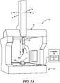
- FIG 1A schematically shows of one type of coordinate measuring machine 10 (i.e., a CMM system, also referred to below as "CMM 10") that may be configured in accordance with illustrative embodiments.
- CMM 10 is but one of a number of different types of CMMs that may implement various embodiments. Accordingly, such a CMM is not intended to limit all embodiments.
- the CMM 10 measures an object 11 (or work piece) on its bed/ base (referred to as "base 101"), which may be formed from granite or other material.
- base 101 defines an X-Y plane that typically is parallel to the plane of the floor supporting the CMM 10.
- the base 101 supports a rotary table 14 that controllably rotates the object 11 relative to the base 101 (discussed below).
- the CMM 10 has movable features 16 (e.g., a carriage 103 and other parts) arranged to move a measuring device 18, such as a probe 18A (e.g., one or more contact or non-contact (e.g., optical) probes, identified as reference number 18A), coupled with a movable arm 20.
- a measuring device 18 such as a probe 18A (e.g., one or more contact or non-contact (e.g., optical) probes, identified as reference number 18A)
- some embodiments move the base 101 with respect to a stationary measuring device 18.
- the movable features 16 of the CMM 10 manipulate the relative positions of the measuring device 18 and the object 11 to obtain the desired measurement.
- the movable features 16 (and its arm 20, discussed below) are movable relative to the base 101.
- the CMM 10 has a control system 22 that controls and coordinates its movements and activities (shown schematically in Figure 1A as "Controller 22"), which may be internal to the CMM 10, external to the CMM 10, or have both internal and external components.
- the control system 22 preferably includes hardware, such as dedicated hardware systems and/or computer processor hardware.
- the computer processor may include a microprocessor, such as a member of the Intel "Core i7" family of integrated circuit microprocessors available from Intel Corporation, or a digital signal processer, such as a member of the TMS320C66x family of digital signal processor integrated circuits from Texas Instruments Incorporated.
- the computer processor has on-board digital memory for storing data and/or computer code, including instructions for implementing some or all of the control system operations and methods.
- the computer processor may be operably coupled to other digital memory, such as RAM or ROM, or a programmable memory circuit for storing such computer code and/or control data.
- some embodiments couple the CMM 10 with an external computer system 24 ("host computer 24").
- host computer 24 an external computer system 24
- Figure 1A shows the computer system 24 as part of the control system, those skilled in the art should understand that it may be separate from the control system 22.
- the host computer 24 has a computer processor such as those described above, and computer memory in communication with the processor of the CMM 10.
- the memory is configured to hold non-transient computer instructions capable of being executed by its processor, and/or to store non-transient data, such as 1) scan path data used to guide the measuring device 18 during a measurement scan, and/or 2) data acquired as a result of the measurements of an object 11 on the base 101.
- the host computer system 24 may be implemented as one or both of a desktop computer, a tower computer, or a laptop computer, such as those available from Dell Inc., or even a tablet computer, such as the IPAD available from Apple Inc.
- the host computer 24 may be coupled to the CMM 10 via a hardwired connection, such as an Ethernet cable, or via a wireless link, such as a Bluetooth link or a WiFi link.
- the host computer 24 may, for example, include software to control the CMM 10 during use or calibration, and/or may include software configured to process data acquired during a calibration process.
- the host computer 24 may include a user interface configured to allow a user to manually or automatically operate the CMM 10.
- the CMM 10 may be considered as having knowledge about the relative locations of the base 101, the rotary table 14, the object 11 on the rotary table, and the measuring device 18. More particularly, the control system 22 and/or computer system 24 may control and store information about the motion of the movable features 16. Alternately, or in addition, the movable features 16 of some embodiments include sensors that sense the locations of the base 101 and/or measuring device 18, and report that data to the control system 22 and/or the computer system 24.
- the information about the motion and position of the base 101 and/or measuring device 18 of the CMM 10 may be recorded in terms of a one dimensional, two-dimensional (e.g., X-Y; X-Z; Y-Z) or three-dimensional (X-Y-Z) coordinate system referenced to a point on the CMM 10.
- a one dimensional, two-dimensional e.g., X-Y; X-Z; Y-Z
- X-Y-Z three-dimensional
- the CMM 10 may have more than three degrees of freedom; i.e., more degrees of freedom in this example than in the X, Y, and Z directions.
- the end of the arm 20 may include a wrist mechanism 60 (e.g., see Figure 6 , discussed below) that rotates the measuring device 18/18A, thus providing up to three more degrees of freedom.
- Some CMMs 100 also include a manual user interface 125 as schematically illustrated in Figure 1B .
- the manual interface 125 may enable the user to change the position of the measuring device 18 or base 101/rotary table 14 (e.g., with respect to one another), and to record data relating to the position of the measuring device 18 or base 101/rotary table 14.
- the manual user interface 125 may have control buttons 125A and joysticks or knobs 125B that allow a user to manually operate the CMM 10.
- the interface 125 also may have a display window 125C (e.g., a liquid crystal display) for showing system positions, and programming certain functions and positions of the measuring device 18 or base 101.
- the manual interface 125 may have a number of other components and thus, the components 125A-125C shown in this drawing are for illustrative purposes only. Other embodiments may omit this manual interface 125. In illustrative embodiments, since the measuring process typically is automated, this interface 125 may not be used.
- the measuring device 18 may also be movable via control buttons 125A.
- the movable features 16 may respond to manual control, or be under control of an internal computer processor, to move the base 101 and/or the measuring device 18 (e.g., a mechanical probe or a laser probe in a mechanical CMM 10) relative to one another. Accordingly, this arrangement permits the object 11 being measured to be presented to the measuring device 18 from a variety of angles, and in a variety of positions.
- FIGS 2-6 schematically show various different probes 18A configured in accordance with illustrative embodiments.
- these probes 18A may be tactile probes, optical probes, or other probes know in the CMM art.
- Those skilled in the art also may refer to probes as "tips" or “styli.” For simplicity, however, this discussion refers to them as probes only.
- probes 18A often are members of a family of probes 18A having different sizes.
- probes 18A of a family may have different shaft lengths and shaft thicknesses to measure a variety of different objects 11. They may be selected based on the type of CMM 10 to be used, and/or the object/workpiece 11 being measured. In either case, potentially due to their limited sizes and lack of surface area, probes in the prior art known to the inventors do not have size identification markings. Instead, a technician measures the probe, or it is positioned in a case or holder identifying its size. To ensure an accurately sized probe, the technician physically measures prior art probes with well calibrated calipers or similar device, which could be cumbersome, error prone, and time consuming.
- prior art probes may not be efficiently usable in automated process that automatically selects probes for CMM processes.
- the inventors recognized these problems and, in response, developed a system that enables vision systems 72 (e.g., see Figure 7 , discussed below) to relatively easily identify a probe despite its limited surface area.
- FIG. 2 schematically shows a tactile probe 18A configured in accordance with illustrative embodiments of the invention.
- this probe 18A has a cylindrical shaft 200, formed from metal or other rigid material, with a proximal end (i.e., the top of the figure of the CMM 10) and a distal end (i.e., the bottom of the figure).
- the proximal end of the shaft 200 has integral coupling hub 202.
- the distal end of the shaft 200 has a sphere 204 formed from a hard material, such as ruby material, for contacting the object 11 being measured.
- the shaft 200 has identification indicia specially configured to efficiently and effectively identify the shaft 200; namely, the indicia provides encoded data that, once obtained, enables the user or logic to determine information about the probe 18A, such as its length and/or diameter. As additional examples, this information may encode data that enables the user or logic to obtain other information, such as the origin of the probe 18A, the manufacturer, the owner, or other information.
- Illustrative embodiments produce the identification indicia in a manner that is more easily readable by vision systems 72.
- the identification indicia preferably is in a visual form that corresponds with Base 3 or Base 4 number systems.
- This visual identification indicia may be formed in any of a variety of manners, such as by additive (paint or deposited material) and/or subtractive processes (e.g., etching).
- the probe 18A has five integral stripes 206 on the shaft 200 encoding a number in Base 3. Three of the stripes 206 in this embodiments are formed in an opaque color (e.g., black), while the two other stripes 206 are formed by the space between two opaque stripes 206.
- the stripes 206 formed by the space simply is the surface color of the shaft 200 (referred to below as having a "transparent" color).
- Other embodiments may use stripes 206 of different opaque colors (e.g., black, blue, green, etc.), and/or may machine the stripes into the shaft 200.
- Each stripe 206 forming the encoded value has a prescribed thickness (i.e., its length along the longitudinal axis of the shaft 200).
- This prescribed thickness is one of three different thicknesses.
- Figure 2 highlights these three sizes from top to bottom of the opaque stripes 206. Specifically:
- the identifying indicia of Figure 2 therefore is considered to encode the Base 3 number 21100, which is equal to 198 in Base 10. Accordingly, the probe 18A of Figure 2 has the identification indicia equal to 198.
- a technician or logic therefore can access a table or database identifying a plurality of different probes 18A, including the probe identified by number 198. The logic or technician then may know the size of the probe 18A using that table.
- logic or a technician may need a specific probe 18A, such as probe 18A identified by number 198 of Figure 2 .
- the logic or technician then may locate the required probe 18A simply by scanning or viewing the identification indicia on a plurality of probes 18A. Those probes 18A may be in the vicinity of the CMM 10, or in an off-site storage location. Then, the probe 18A identified by number 198 may be obtained and then coupled with the CMM 10 for use in a measurement operation.
- identifying a probe 18A or looking for a probe 18A with specific identifying indicia various embodiments either manually view the identifying indicia, or use vision systems 72 to scan the identifying indicia. Either way, the inventors recognized that use of higher base numbering systems can present difficulties with accuracy of either method - especially with lower resolution vision systems 72.
- Base 3 numbering system only requires three different thicknesses for the various bands, and with five digits, enables up to 242 possible probe types.
- Higher base numbering systems may enable more possible probe types for the same number of stripes. Undesirably, however, higher base number systems require more stripe thicknesses.
- Using higher base numbering systems therefore can cause errors due to the limitations of various scanners and vision systems 72. Accordingly, these higher base numbering systems undesirably can reduce the signal to noise ratio of the vision systems 72, requiring higher quality (and often higher cost) optics.
- illustrative embodiments add a calibration stripe 208 to the shaft 200.
- this calibration stripe 208 has a known thickness against which all of the stripes 206 may be compared.
- the calibration stripe 208 can be set to one unit, and the Base 3 system can have stripes 206 that are the same thickness as the calibration stripe 208, twice the calibration stipe thickness, or three times the calibration stripe thickness.
- the calibration stripe 208 thus acts as a built-in ruler against which to make simple measurements.
- the calibration stripe 208 can be positioned at any of a variety of different locations along the shaft 200. One embodiment positions the calibration stripe 208 near the distal end of the shaft 200. In some embodiments, the calibration stripe 208 extends from the distal end of the shaft 200 to the first, distal-most opaque stripe 206. For example, in Figures 2-5 , the calibration stripe 208 extends the distance from the distal tip of the shaft 200 to the beginning of the closest opaque stripe 206. As such, after measuring the calibration stripe 208, logic may use its length as input into a formula that provides precise calibration information (e.g., divide the length by 4 for the lowest thickness stripe 206).
- the calibration stripe 208 is simply the native shaft color and larger than many of the stripes 206. Accordingly, like other stripes 206, the calibration stripe 208 in such an embodiment may be considered to be transparent-it has the color of the shaft 200. Some embodiments, however, may form the calibration stripe 208 from opaque material, as shown in Figure 2 . Other embodiments may position the calibration stripe 208 at a different location, such as at the proximal end of the shaft 200, or some point therebetween. As noted, this calibration stripe 208 may be opaque or transparent (i.e., the color of the opaque stripes and bounded by the opaque stripes on its top and bottom).
- Some embodiments may form a calibration strip directly into the strips/indicia used to identify the number-thus integrating the calibration information directly into the stripe itself (i.e., it forms a portion of the stripe).
- Figure 3 shows two different types of such self-calibrating stripes. It should be noted that these two different types of stripes 206/208, as well as the non-self-calibrating stripes 208 of Figure 3 , do not necessarily have all three different types of stripes.
- some embodiments may include two or more different types of indicia, such as self-calibrating stripes 206/208 and non-self-calibrating stripes 208, to enable use of different vision systems 72.
- a probe 200 may have a first non-self calibrating set of indicia and two sets of self-calibrating indicia for identification by three different systems.
- the two different self-calibrating stripes 206A and 206B of Figure 3 are merely two examples of such stripes. As shown, both stripes have varying thicknesses with different stepped portions. In these examples, the thinnest stepped portions of the stripes 206A and 206B serve as the calibration portion and the thickest portion serves to identify the number in Base 3 (or Base 4, as discussed below). This pattern preferably is periodically repeated around the probe to the extent possible for maximum visualization by the vision systems 72.
- vision systems 72 may image the thin stepped portion as the calibration portion, and then recognize that the widest stepped portion is two times the width of the calibration portion. The widest portion thus identifies the number in Base 3 for that stripe. In a similar manner, for the stripe 206B, the widest stepped portion is four times the size of the calibration stripe. The vision system 72 therefore may use the widest stepped portion to identify the Base 3 number for that stripe.
- FIG. 3 schematically shows the probe 18A of Figure 2 , but with a Base 4 numbering system. This example therefore shows four different stripe thicknesses.
- Using a Base 4 number system with five digits favorably enables up to 1023 possible probe types, which is more than four times the options of a similar Base 3 system.
- If using opaque stripes 206, then the Base 4 system of Figure 3 may require only 4 digits to enable up to 255 possible types.
- the figures are not drawn to scale. These figures nevertheless show that the shaft 200 has very little surface area for printing identification indicia relating to the shaft 200. Even though they have only two thicknesses, a conventional bar code, for example, which is Base 2, would likely produce many stripes 206 that may have trouble fitting on smaller probes 18A. Base 3 and 4 numbering systems therefore are preferred. Despite that, other embodiments may apply to other numbering systems and other types of indicia. For example, the stripes 206 may encircle the shaft 200, or only extend part way around the shaft 200. Other embodiments may use different shapes (e.g., dashes), with the risk of vision systems 72 having difficulty acquiring their images.
- Some embodiments may vary some other parameter of the identification indicia other than stripe thickness. For example, some embodiments may vary colors and maintain the stripe thickness uniform. Others may vary the shapes of the indicia in some other manner. Some embodiments, may encode directly within the stripes 206. For example, each stripe 206 may have a prescribed pattern encoded with certain data. This encoding scheme may be used separately from other bands 206, or in combination with other stripes 206.
- tactile probes 18A is by example only. Other embodiments apply to other types of probes 18A.
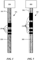
- Figures 4 and 5 respectively show a first optical probe 18A using the Base 3 identification indicia, and a second optical probe 18A using the Base 4 identification indicia.
- Figure 6 schematically shows a CMM with multiple probes/styli 18A configured in accordance with illustrative embodiments.
- the movable arm 20 (the -Z ram) has the prior noted wrist 60, which supports one or more extensions or adapters 65 that can support a plurality of probes 18A.
- extensions or adapters 65 that can support a plurality of probes 18A.
- Some embodiments extend beyond CMMs, such as the CMM 10 of Figures 1A and 1B .
- some embodiments apply to additive printer machines, CNC machines, and other devices that use a probe 18A.
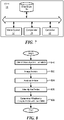
- Figure 7 schematically shows some portions of the CMM that may implement illustrative embodiments. Each of these components is operatively connected by any conventional interconnect mechanism. Figure 7 simply shows a bus communicating each the components. Those skilled in the art should understand that this generalized representation can be modified to include other conventional direct or indirect connections. Accordingly, discussion of a bus is not intended to limit various embodiments.
- Figure 7 only schematically shows each of these components.
- the comparator 74 may be implemented using a plurality of microprocessors executing firmware.
- the comparator 74 may be implemented using one or more application specific integrated circuits (i.e., "ASICs") and related software, or a combination of ASICs, discrete electronic components (e.g., transistors), and microprocessors.
- ASICs application specific integrated circuits
- the representation of the comparator 74 and other components in a single box of Figure 7 is for simplicity purposes only.
- the comparator 74 of Figure 7 is distributed across a plurality of different machines - not necessarily within the same housing or chassis.
- Figure 7 is a significantly simplified representation of an actual coordinate measuring machine. Those skilled in the art should understand that such a device has many other physical and functional components. Accordingly, this discussion is in no way intended to suggest that Figure 7 represents all of the elements of a coordinate measuring machine.
- the coordinate measuring machine has a vision system 72 that can image/capture the noted visual identification indicia on the probe(s), as well as the prior noted comparator 74 for comparing the imaged visual identification indicia against some known data, such as some indicia key in a database 70.
- the vision system 72 may a) be integrated into the coordinate measuring machine, b) be separate from the coordinate measuring machine, c) have portions that are both part of and separate from the coordinate measuring machine 10, and/or d) be removably couplable with the coordinate measuring machine 10.
- the vision system 72 may be a hand-held device that is largely unconnected with the coordinate measuring machine 10.
- the vision system 72 may be part of a larger vision system 72 integrated into the coordinate measuring machine 10 and may be used for a plurality of additional functions (e.g., locating the workpiece).
- Figure 7 also shows the prior noted controller 22 of Figure 1 , which performs a number of additional functions after receipt of the imaged visual identification indicia.
- Figure 8 shows a process of selecting a probe 18A from a set of one or more probes in accordance with illustrative embodiments of the invention. It should be noted that this process is substantially simplified from a longer process that normally would be used to select a probe 18A. Accordingly, the process can have many steps. In addition, some of the steps may be performed in a different order than that shown, or at the same time. Those skilled in the art therefore can modify the process as appropriate. Moreover, as noted above and below, certain functional components noted are merely examples of certain structures that may be used. Those skilled in the art can select the appropriate functional components depending upon the application and other constraints. Accordingly, discussion of specific functional components is not intended to limit all embodiments.
- the process of Figure 8 begins at step 800, which directs the vision system 72 toward the indicia on a given probe 18A of a set of probes 18A.
- the CMM 10 is part of a system that is usable with a set of different probes 18A that each may be appropriate for specific workpieces.
- a tactile probe 18A with a long, thin shaft may be more appropriate for use with workpiece having a long thin hole.
- a probe 18A with a wide and/or a short shaft likely is less desirable than the former noted probe 18A.
- the process images the indicia.
- the vision system 72 can have lower sensitivity scanners than those required for imaging higher encoded indicia (e.g., Base 5 or Base 6). Accordingly, the signal to noise ratio favorably may remain within reasonable tolerances with lower cost, readily accessible image systems and still provide satisfactory results.
- Step 804 then analyzes the indicia.
- the controller 22 may use the calibration stripe 208 (whether it is integrated into the stripe(s) 206 or separate from the stripes 206) to compare against the various stripes 206 along the shaft to decode, calculate or determine the number encoded by the stripes 206.
- Step 806 then may call upon the controller 22 to compare the decoded indicia against some "indicia key" - prescribed numbers data stored in the database 70.
- the database 70 may have a table with plurality of numbers that each are associated with, among other things, specific probe lengths, widths, and probe types (e.g., tactile or non-contact probes).
- the controller 22 may have logic that applies the decoded visual indicia into an algorithm or formula to match with one of the set of probes.
- step 808 determines whether the probe 18A just identified should be coupled with the coordinate measuring machine 10. In other words, step 808 may use the controller 22 to determine if the identified probe 18A is appropriate or desired for use in measuring a specific workpiece. If not, then the process may repeat for another probe 18A in the set (if any are left). If the probe 18A is the appropriate or desired probe 18A, however, then the probe 18A may be coupled with the movable part of the coordinate measuring machine 10. To that end, the proximal end of the probe 18A may be removably coupled in a conventional manner to the movable arm 20 (e.g., using magnets and/or a mechanical coupling mechanism).
- illustrative embodiments can properly mark/identify the limited real estate available on a CMM probe 18A, enabling automated and/or more effective use of the underlying coordinate measuring machines 10.
- embodiments of the invention may be implemented at least in part in any conventional computer programming language.
- some embodiments may be implemented in a procedural programming language (e.g ., "C"), or in an object oriented programming language (e.g ., "C++").
- object oriented programming language e.g ., "C++”
- Other embodiments of the invention may be implemented as a pre-configured, stand-along hardware element and/or as preprogrammed hardware elements (e.g ., application specific integrated circuits, FPGAs, and digital signal processors), or other related components.
- the disclosed apparatus and methods may be implemented as a computer program product for use with a computer system.
- Such implementation may include a series of computer instructions fixed either on a tangible, non-transitory medium, such as a computer readable medium (e.g ., a diskette, CD-ROM, ROM, or fixed disk).
- a computer readable medium e.g ., a diskette, CD-ROM, ROM, or fixed disk.
- the series of computer instructions can embody all or part of the functionality previously described herein with respect to the system.
- Such computer instructions can be written in a number of programming languages for use with many computer architectures or operating systems.
- such instructions may be stored in any memory device, such as semiconductor, magnetic, optical or other memory devices, and may be transmitted using any communications technology, such as optical, infrared, microwave, or other transmission technologies.
- such a computer program product may be distributed as a removable medium with accompanying printed or electronic documentation (e.g. , shrink wrapped software), preloaded with a computer system (e.g ., on system ROM or fixed disk), or distributed from a server or electronic bulletin board over the network (e.g. , the Internet or World Wide Web).
- a computer system e.g., on system ROM or fixed disk
- a server or electronic bulletin board over the network
- some embodiments may be implemented in a software-as-a-service model ("SAAS") or cloud computing model.
- SAAS software-as-a-service model
- some embodiments of the invention may be implemented as a combination of both software (e.g ., a computer program product) and hardware. Still other embodiments of the invention are implemented as entirely hardware, or entirely software.
Landscapes
- Physics & Mathematics (AREA)
- General Physics & Mathematics (AREA)
- Length Measuring Devices With Unspecified Measuring Means (AREA)
- A Measuring Device Byusing Mechanical Method (AREA)
Description
- This patent application claims priority from provisional
United States Patent Application number 62/566,644, filed October 2, 2017 entitled, "PROBE IDENTIFICATION APPARATUS AND METHOD," and naming Gurpreet Singh, Milan Kocic, and Michael Mariani - Various embodiments of the invention relate to identifying probes for use with coordinate measurement machines.
- Coordinate measuring machines (CMMs) are widely used for accurately measuring a wide variety of different types of work pieces/ objects. For example, CMMs can measure critical dimensions of aircraft engine components, surgical tools, and gun barrels. Precise and accurate measurements help ensure that their underlying systems, such as an aircraft in the case of aircraft components, operate as specified.
- CMMs often use one or more tactile or optical probes to measure an object. Proper identification of the correct probe can be critical to accurate measurement.
- Devices or systems belonging to the general state of the art are e.g. disclosed in
US 5,825,666 A ,US 3,176,847 A andUS 2002/111766 Al . - In accordance with an embodiment, a probe for coupling with a movable portion of a coordinate measuring machine is defined according to claim 1.
- In accordance with other embodiments, a method of identifying a probe is defined according to claim 7.
-
Figures 2 to 5 and8 show embodiments of the present invention. Figures la, lb, 6 and 7 show further examples which are not encompassed in the scope of the invention, even if they are named "embodiments" in the corresponding parts of the description. The scope of protection is defined by the claims. -
Figure 1A schematically shows a coordinate measuring machine (CMM) . -
Figure 1B schematically shows a user interface that may be used with the CMM ofFigure 1A . -
Figure 2 schematically shows a CMM probe configured in accordance with a first embodiment. -
Figure 3 schematically shows a CMM probe configured in accordance with a second embodiment. -
Figure 4 schematically shows a CMM probe configured in accordance with a third embodiment. -
Figure 5 schematically shows a CMM probe configured in accordance with a fourth embodiment. -
Figure 6 schematically shows a CMM with multiple probes. -
Figure 7 schematically shows some portions of the CMM. -
Figure 8 shows a process of selecting a probe in accordance with illustrative embodiments of the invention. - In illustrative embodiments, a coordinate measuring machine probe has indicia identifying it on its exterior surface, which has little surface area. To that end, the indicia preferably includes one or more stripes of varying thicknesses. To minimize the varying thicknesses and limit the total number of stripes, the indicia may include stripes encoded using Base 3 or Base 4 number systems. Accordingly, vision systems may more easily discern the indicia to identify the probe. This functionality thus enables a wider variety of lower cost vision systems for accurately identifying the indicia. Details of illustrative embodiments are discussed below.
-
Figure 1A schematically shows of one type of coordinate measuring machine 10 (i.e., a CMM system, also referred to below as "CMM 10") that may be configured in accordance with illustrative embodiments. Indeed, thisCMM 10 is but one of a number of different types of CMMs that may implement various embodiments. Accordingly, such a CMM is not intended to limit all embodiments. - As known by those in the art, the
CMM 10, measures an object 11 (or work piece) on its bed/ base (referred to as "base 101"), which may be formed from granite or other material. Generally, thebase 101 defines an X-Y plane that typically is parallel to the plane of the floor supporting theCMM 10. In illustrative embodiments, thebase 101 supports a rotary table 14 that controllably rotates theobject 11 relative to the base 101 (discussed below). - To measure the
object 11, theCMM 10 has movable features 16 (e.g., a carriage 103 and other parts) arranged to move ameasuring device 18, such as aprobe 18A (e.g., one or more contact or non-contact (e.g., optical) probes, identified asreference number 18A), coupled with amovable arm 20. Alternately, some embodiments move thebase 101 with respect to astationary measuring device 18. Either way, themovable features 16 of theCMM 10 manipulate the relative positions of themeasuring device 18 and theobject 11 to obtain the desired measurement. In either case, the movable features 16 (and itsarm 20, discussed below) are movable relative to thebase 101. - The
CMM 10 has acontrol system 22 that controls and coordinates its movements and activities (shown schematically inFigure 1A as "Controller 22"), which may be internal to theCMM 10, external to theCMM 10, or have both internal and external components. Among other things, thecontrol system 22 preferably includes hardware, such as dedicated hardware systems and/or computer processor hardware. Among other things, the computer processor may include a microprocessor, such as a member of the Intel "Core i7" family of integrated circuit microprocessors available from Intel Corporation, or a digital signal processer, such as a member of the TMS320C66x family of digital signal processor integrated circuits from Texas Instruments Incorporated. The computer processor has on-board digital memory for storing data and/or computer code, including instructions for implementing some or all of the control system operations and methods. Alternatively, or in addition, the computer processor may be operably coupled to other digital memory, such as RAM or ROM, or a programmable memory circuit for storing such computer code and/or control data. - Alternately, or in addition, some embodiments couple the
CMM 10 with an external computer system 24 ("host computer 24"). AlthoughFigure 1A shows thecomputer system 24 as part of the control system, those skilled in the art should understand that it may be separate from thecontrol system 22. In a manner similar to thecontrol system 22, thehost computer 24 has a computer processor such as those described above, and computer memory in communication with the processor of theCMM 10. The memory is configured to hold non-transient computer instructions capable of being executed by its processor, and/or to store non-transient data, such as 1) scan path data used to guide themeasuring device 18 during a measurement scan, and/or 2) data acquired as a result of the measurements of anobject 11 on thebase 101. - Among other things, the
host computer system 24 may be implemented as one or both of a desktop computer, a tower computer, or a laptop computer, such as those available from Dell Inc., or even a tablet computer, such as the IPAD available from Apple Inc. Thehost computer 24 may be coupled to the CMM 10 via a hardwired connection, such as an Ethernet cable, or via a wireless link, such as a Bluetooth link or a WiFi link. As part of thecontrol system 22, thehost computer 24 may, for example, include software to control theCMM 10 during use or calibration, and/or may include software configured to process data acquired during a calibration process. In addition, thehost computer 24 may include a user interface configured to allow a user to manually or automatically operate theCMM 10. - Because their relative positions typically are determined by the action of the
movable features 16, theCMM 10 may be considered as having knowledge about the relative locations of thebase 101, the rotary table 14, theobject 11 on the rotary table, and themeasuring device 18. More particularly, thecontrol system 22 and/orcomputer system 24 may control and store information about the motion of themovable features 16. Alternately, or in addition, themovable features 16 of some embodiments include sensors that sense the locations of thebase 101 and/or measuringdevice 18, and report that data to thecontrol system 22 and/or thecomputer system 24. The information about the motion and position of thebase 101 and/or measuringdevice 18 of theCMM 10 may be recorded in terms of a one dimensional, two-dimensional (e.g., X-Y; X-Z; Y-Z) or three-dimensional (X-Y-Z) coordinate system referenced to a point on theCMM 10. - The CMM 10 may have more than three degrees of freedom; i.e., more degrees of freedom in this example than in the X, Y, and Z directions. For example, the end of the
arm 20 may include a wrist mechanism 60 (e.g., seeFigure 6 , discussed below) that rotates themeasuring device 18/18A, thus providing up to three more degrees of freedom. - Some CMMs 100 also include a
manual user interface 125 as schematically illustrated inFigure 1B . Among other things, themanual interface 125 may enable the user to change the position of themeasuring device 18 orbase 101/rotary table 14 (e.g., with respect to one another), and to record data relating to the position of themeasuring device 18 orbase 101/rotary table 14. To that end, themanual user interface 125 may havecontrol buttons 125A and joysticks orknobs 125B that allow a user to manually operate theCMM 10. Theinterface 125 also may have adisplay window 125C (e.g., a liquid crystal display) for showing system positions, and programming certain functions and positions of the measuringdevice 18 orbase 101. Of course, themanual interface 125 may have a number of other components and thus, thecomponents 125A-125C shown in this drawing are for illustrative purposes only. Other embodiments may omit thismanual interface 125. In illustrative embodiments, since the measuring process typically is automated, thisinterface 125 may not be used. - In a moving
table CMM 10, for example, the measuringdevice 18 may also be movable viacontrol buttons 125A. As such, themovable features 16 may respond to manual control, or be under control of an internal computer processor, to move thebase 101 and/or the measuring device 18 (e.g., a mechanical probe or a laser probe in a mechanical CMM 10) relative to one another. Accordingly, this arrangement permits theobject 11 being measured to be presented to the measuringdevice 18 from a variety of angles, and in a variety of positions. -
Figures 2-6 schematically show variousdifferent probes 18A configured in accordance with illustrative embodiments. As noted above, theseprobes 18A may be tactile probes, optical probes, or other probes know in the CMM art. Those skilled in the art also may refer to probes as "tips" or "styli." For simplicity, however, this discussion refers to them as probes only. -
Individual probes 18A often are members of a family ofprobes 18A having different sizes. For example, probes 18A of a family may have different shaft lengths and shaft thicknesses to measure a variety ofdifferent objects 11. They may be selected based on the type ofCMM 10 to be used, and/or the object/workpiece 11 being measured. In either case, potentially due to their limited sizes and lack of surface area, probes in the prior art known to the inventors do not have size identification markings. Instead, a technician measures the probe, or it is positioned in a case or holder identifying its size. To ensure an accurately sized probe, the technician physically measures prior art probes with well calibrated calipers or similar device, which could be cumbersome, error prone, and time consuming. Moreover, prior art probes may not be efficiently usable in automated process that automatically selects probes for CMM processes. The inventors recognized these problems and, in response, developed a system that enables vision systems 72 (e.g., seeFigure 7 , discussed below) to relatively easily identify a probe despite its limited surface area. - To that end,
Figure 2 schematically shows atactile probe 18A configured in accordance with illustrative embodiments of the invention. As with many other probes, thisprobe 18A has acylindrical shaft 200, formed from metal or other rigid material, with a proximal end (i.e., the top of the figure of the CMM 10) and a distal end (i.e., the bottom of the figure). To couple with the movable arm of theCMM 10, the proximal end of theshaft 200 hasintegral coupling hub 202. In a corresponding manner, the distal end of theshaft 200 has asphere 204 formed from a hard material, such as ruby material, for contacting theobject 11 being measured. - In accordance with illustrative embodiments, the
shaft 200 has identification indicia specially configured to efficiently and effectively identify theshaft 200; namely, the indicia provides encoded data that, once obtained, enables the user or logic to determine information about theprobe 18A, such as its length and/or diameter. As additional examples, this information may encode data that enables the user or logic to obtain other information, such as the origin of theprobe 18A, the manufacturer, the owner, or other information. - Illustrative embodiments produce the identification indicia in a manner that is more easily readable by
vision systems 72. To that end, in illustrative embodiments, the identification indicia preferably is in a visual form that corresponds with Base 3 or Base 4 number systems. This visual identification indicia may be formed in any of a variety of manners, such as by additive (paint or deposited material) and/or subtractive processes (e.g., etching). In the example ofFigure 2 , theprobe 18A has fiveintegral stripes 206 on theshaft 200 encoding a number in Base 3. Three of thestripes 206 in this embodiments are formed in an opaque color (e.g., black), while the twoother stripes 206 are formed by the space between twoopaque stripes 206. Accordingly, thestripes 206 formed by the space simply is the surface color of the shaft 200 (referred to below as having a "transparent" color). Other embodiments, however, may usestripes 206 of different opaque colors (e.g., black, blue, green, etc.), and/or may machine the stripes into theshaft 200. - Each
stripe 206 forming the encoded value has a prescribed thickness (i.e., its length along the longitudinal axis of the shaft 200). This prescribed thickness, however, is one of three different thicknesses. For illustrative purposes,Figure 2 highlights these three sizes from top to bottom of theopaque stripes 206. Specifically: - A thickest stripe 206 (value of 2);
- A medium thickness stripe 206 (value of 1);
- A thin stripe 206 (value of 0).
- The identifying indicia of
Figure 2 therefore is considered to encode the Base 3 number 21100, which is equal to 198 inBase 10. Accordingly, theprobe 18A ofFigure 2 has the identification indicia equal to 198. A technician or logic therefore can access a table or database identifying a plurality ofdifferent probes 18A, including the probe identified by number 198. The logic or technician then may know the size of theprobe 18A using that table. - Alternatively, logic or a technician may need a
specific probe 18A, such asprobe 18A identified by number 198 ofFigure 2 . The logic or technician then may locate the requiredprobe 18A simply by scanning or viewing the identification indicia on a plurality ofprobes 18A. Thoseprobes 18A may be in the vicinity of theCMM 10, or in an off-site storage location. Then, theprobe 18A identified by number 198 may be obtained and then coupled with theCMM 10 for use in a measurement operation. - Whether identifying a
probe 18A or looking for aprobe 18A with specific identifying indicia, various embodiments either manually view the identifying indicia, or usevision systems 72 to scan the identifying indicia. Either way, the inventors recognized that use of higher base numbering systems can present difficulties with accuracy of either method - especially with lowerresolution vision systems 72. Specifically, Base 3 numbering system only requires three different thicknesses for the various bands, and with five digits, enables up to 242 possible probe types. Higher base numbering systems may enable more possible probe types for the same number of stripes. Undesirably, however, higher base number systems require more stripe thicknesses. Using higher base numbering systems therefore can cause errors due to the limitations of various scanners andvision systems 72. Accordingly, these higher base numbering systems undesirably can reduce the signal to noise ratio of thevision systems 72, requiring higher quality (and often higher cost) optics. - Some embodiments measure the
stripes 206 to determine the encoded data. Other embodiments, however, simply compare the thicknesses of thestripes 206 to determine the encoded identification information. This latter method may present some problems, however, when all thestripes 206 are the same size. To obviate that issue, illustrative embodiments add acalibration stripe 208 to theshaft 200. Specifically, thiscalibration stripe 208 has a known thickness against which all of thestripes 206 may be compared. For example, inFigure 2 , thecalibration stripe 208 can be set to one unit, and the Base 3 system can havestripes 206 that are the same thickness as thecalibration stripe 208, twice the calibration stipe thickness, or three times the calibration stripe thickness. Thecalibration stripe 208 thus acts as a built-in ruler against which to make simple measurements. - The
calibration stripe 208 can be positioned at any of a variety of different locations along theshaft 200. One embodiment positions thecalibration stripe 208 near the distal end of theshaft 200. In some embodiments, thecalibration stripe 208 extends from the distal end of theshaft 200 to the first, distal-mostopaque stripe 206. For example, inFigures 2-5 , thecalibration stripe 208 extends the distance from the distal tip of theshaft 200 to the beginning of the closestopaque stripe 206. As such, after measuring thecalibration stripe 208, logic may use its length as input into a formula that provides precise calibration information (e.g., divide the length by 4 for the lowest thickness stripe 206). - In this example, the
calibration stripe 208 is simply the native shaft color and larger than many of thestripes 206. Accordingly, likeother stripes 206, thecalibration stripe 208 in such an embodiment may be considered to be transparent-it has the color of theshaft 200. Some embodiments, however, may form thecalibration stripe 208 from opaque material, as shown inFigure 2 . Other embodiments may position thecalibration stripe 208 at a different location, such as at the proximal end of theshaft 200, or some point therebetween. As noted, thiscalibration stripe 208 may be opaque or transparent (i.e., the color of the opaque stripes and bounded by the opaque stripes on its top and bottom). - Some embodiments, however, may form a calibration strip directly into the strips/indicia used to identify the number-thus integrating the calibration information directly into the stripe itself (i.e., it forms a portion of the stripe). For simplicity,
Figure 3 shows two different types of such self-calibrating stripes. It should be noted that these two different types ofstripes 206/208, as well as the non-self-calibratingstripes 208 ofFigure 3 , do not necessarily have all three different types of stripes. However, some embodiments may include two or more different types of indicia, such as self-calibratingstripes 206/208 and non-self-calibratingstripes 208, to enable use ofdifferent vision systems 72. For example, aprobe 200 may have a first non-self calibrating set of indicia and two sets of self-calibrating indicia for identification by three different systems. - The two different self-calibrating
stripes Figure 3 are merely two examples of such stripes. As shown, both stripes have varying thicknesses with different stepped portions. In these examples, the thinnest stepped portions of thestripes vision systems 72. - Accordingly, for the
stripe 206A,vision systems 72 may image the thin stepped portion as the calibration portion, and then recognize that the widest stepped portion is two times the width of the calibration portion. The widest portion thus identifies the number in Base 3 for that stripe. In a similar manner, for thestripe 206B, the widest stepped portion is four times the size of the calibration stripe. Thevision system 72 therefore may use the widest stepped portion to identify the Base 3 number for that stripe. - The inventors recognized that Base 4 numbering systems also may provide satisfactory results, although with more possibility of error due to the additional stripe thickness requirement.
Figure 3 schematically shows theprobe 18A ofFigure 2 , but with a Base 4 numbering system. This example therefore shows four different stripe thicknesses. Using a Base 4 number system with five digits favorably enables up to 1023 possible probe types, which is more than four times the options of a similar Base 3 system. If usingopaque stripes 206, then the Base 4 system ofFigure 3 may require only 4 digits to enable up to 255 possible types. - Indeed, the figures are not drawn to scale. These figures nevertheless show that the
shaft 200 has very little surface area for printing identification indicia relating to theshaft 200. Even though they have only two thicknesses, a conventional bar code, for example, which isBase 2, would likely producemany stripes 206 that may have trouble fitting onsmaller probes 18A. Base 3 and 4 numbering systems therefore are preferred. Despite that, other embodiments may apply to other numbering systems and other types of indicia. For example, thestripes 206 may encircle theshaft 200, or only extend part way around theshaft 200. Other embodiments may use different shapes (e.g., dashes), with the risk ofvision systems 72 having difficulty acquiring their images. - Some embodiments may vary some other parameter of the identification indicia other than stripe thickness. For example, some embodiments may vary colors and maintain the stripe thickness uniform. Others may vary the shapes of the indicia in some other manner. Some embodiments, may encode directly within the
stripes 206. For example, eachstripe 206 may have a prescribed pattern encoded with certain data. This encoding scheme may be used separately fromother bands 206, or in combination withother stripes 206. - It should be reiterated that discussion of
tactile probes 18A is by example only. Other embodiments apply to other types ofprobes 18A.Figures 4 and 5 respectively show a firstoptical probe 18A using the Base 3 identification indicia, and a secondoptical probe 18A using the Base 4 identification indicia. -
Figure 6 schematically shows a CMM with multiple probes/styli 18A configured in accordance with illustrative embodiments. In this example, the movable arm 20 (the -Z ram) has the priornoted wrist 60, which supports one or more extensions oradapters 65 that can support a plurality ofprobes 18A. Those skilled in the art can extend this example to a variety of different multi-probe configurations using theseextensions 65. - Some embodiments extend beyond CMMs, such as the
CMM 10 ofFigures 1A and1B . For example, some embodiments apply to additive printer machines, CNC machines, and other devices that use aprobe 18A. -
Figure 7 schematically shows some portions of the CMM that may implement illustrative embodiments. Each of these components is operatively connected by any conventional interconnect mechanism.Figure 7 simply shows a bus communicating each the components. Those skilled in the art should understand that this generalized representation can be modified to include other conventional direct or indirect connections. Accordingly, discussion of a bus is not intended to limit various embodiments. - Indeed, it should be noted that
Figure 7 only schematically shows each of these components. Those skilled in the art should understand that each of these components can be implemented in a variety of conventional manners, such as by using hardware, software, or a combination of hardware and software, across one or more other functional components. For example, thecomparator 74 may be implemented using a plurality of microprocessors executing firmware. As another example, thecomparator 74 may be implemented using one or more application specific integrated circuits (i.e., "ASICs") and related software, or a combination of ASICs, discrete electronic components (e.g., transistors), and microprocessors. Accordingly, the representation of thecomparator 74 and other components in a single box ofFigure 7 is for simplicity purposes only. In fact, in some embodiments, thecomparator 74 ofFigure 7 is distributed across a plurality of different machines - not necessarily within the same housing or chassis. - It should be reiterated that the representation of
Figure 7 is a significantly simplified representation of an actual coordinate measuring machine. Those skilled in the art should understand that such a device has many other physical and functional components. Accordingly, this discussion is in no way intended to suggest thatFigure 7 represents all of the elements of a coordinate measuring machine. - As shown, the coordinate measuring machine has a
vision system 72 that can image/capture the noted visual identification indicia on the probe(s), as well as the priornoted comparator 74 for comparing the imaged visual identification indicia against some known data, such as some indicia key in adatabase 70. Thevision system 72 may a) be integrated into the coordinate measuring machine, b) be separate from the coordinate measuring machine, c) have portions that are both part of and separate from the coordinate measuringmachine 10, and/or d) be removably couplable with the coordinate measuringmachine 10. For example, thevision system 72 may be a hand-held device that is largely unconnected with the coordinate measuringmachine 10. As a contrasting example, thevision system 72 may be part of alarger vision system 72 integrated into the coordinate measuringmachine 10 and may be used for a plurality of additional functions (e.g., locating the workpiece).Figure 7 also shows the priornoted controller 22 ofFigure 1 , which performs a number of additional functions after receipt of the imaged visual identification indicia. -
Figure 8 shows a process of selecting aprobe 18A from a set of one or more probes in accordance with illustrative embodiments of the invention. It should be noted that this process is substantially simplified from a longer process that normally would be used to select aprobe 18A. Accordingly, the process can have many steps. In addition, some of the steps may be performed in a different order than that shown, or at the same time. Those skilled in the art therefore can modify the process as appropriate. Moreover, as noted above and below, certain functional components noted are merely examples of certain structures that may be used. Those skilled in the art can select the appropriate functional components depending upon the application and other constraints. Accordingly, discussion of specific functional components is not intended to limit all embodiments. - The process of
Figure 8 begins atstep 800, which directs thevision system 72 toward the indicia on a givenprobe 18A of a set ofprobes 18A. In illustrative embodiments, theCMM 10 is part of a system that is usable with a set ofdifferent probes 18A that each may be appropriate for specific workpieces. For example, atactile probe 18A with a long, thin shaft may be more appropriate for use with workpiece having a long thin hole. Thus, aprobe 18A with a wide and/or a short shaft likely is less desirable than the formernoted probe 18A. - After directing the
vision system 72 to the indicia, the process images the indicia. When using indicia encoded as Base 3 and/or Base 4 numbers, thevision system 72 can have lower sensitivity scanners than those required for imaging higher encoded indicia (e.g., Base 5 or Base 6). Accordingly, the signal to noise ratio favorably may remain within reasonable tolerances with lower cost, readily accessible image systems and still provide satisfactory results. - Step 804 then analyzes the indicia. First, in the
embodiment using stripes controller 22 may use the calibration stripe 208 (whether it is integrated into the stripe(s) 206 or separate from the stripes 206) to compare against thevarious stripes 206 along the shaft to decode, calculate or determine the number encoded by thestripes 206. Step 806 then may call upon thecontroller 22 to compare the decoded indicia against some "indicia key" - prescribed numbers data stored in thedatabase 70. For example, thedatabase 70 may have a table with plurality of numbers that each are associated with, among other things, specific probe lengths, widths, and probe types (e.g., tactile or non-contact probes). As another example, thecontroller 22 may have logic that applies the decoded visual indicia into an algorithm or formula to match with one of the set of probes. - After identifying the probe in
step 806,step 808 determines whether theprobe 18A just identified should be coupled with the coordinate measuringmachine 10. In other words, step 808 may use thecontroller 22 to determine if the identifiedprobe 18A is appropriate or desired for use in measuring a specific workpiece. If not, then the process may repeat for anotherprobe 18A in the set (if any are left). If theprobe 18A is the appropriate or desiredprobe 18A, however, then theprobe 18A may be coupled with the movable part of the coordinate measuringmachine 10. To that end, the proximal end of theprobe 18A may be removably coupled in a conventional manner to the movable arm 20 (e.g., using magnets and/or a mechanical coupling mechanism). - Accordingly, illustrative embodiments can properly mark/identify the limited real estate available on a
CMM probe 18A, enabling automated and/or more effective use of the underlying coordinate measuringmachines 10. - Various embodiments of the invention may be implemented at least in part in any conventional computer programming language. For example, some embodiments may be implemented in a procedural programming language (e.g., "C"), or in an object oriented programming language (e.g., "C++"). Other embodiments of the invention may be implemented as a pre-configured, stand-along hardware element and/or as preprogrammed hardware elements (e.g., application specific integrated circuits, FPGAs, and digital signal processors), or other related components.
- In an alternative embodiment, the disclosed apparatus and methods (e.g., see the various flow charts described above) may be implemented as a computer program product for use with a computer system. Such implementation may include a series of computer instructions fixed either on a tangible, non-transitory medium, such as a computer readable medium (e.g., a diskette, CD-ROM, ROM, or fixed disk). The series of computer instructions can embody all or part of the functionality previously described herein with respect to the system.
- Those skilled in the art should appreciate that such computer instructions can be written in a number of programming languages for use with many computer architectures or operating systems. Furthermore, such instructions may be stored in any memory device, such as semiconductor, magnetic, optical or other memory devices, and may be transmitted using any communications technology, such as optical, infrared, microwave, or other transmission technologies.
- Among other ways, such a computer program product may be distributed as a removable medium with accompanying printed or electronic documentation (e.g., shrink wrapped software), preloaded with a computer system (e.g., on system ROM or fixed disk), or distributed from a server or electronic bulletin board over the network (e.g., the Internet or World Wide Web). In fact, some embodiments may be implemented in a software-as-a-service model ("SAAS") or cloud computing model. Of course, some embodiments of the invention may be implemented as a combination of both software (e.g., a computer program product) and hardware. Still other embodiments of the invention are implemented as entirely hardware, or entirely software.
- Although the above discussion discloses various exemplary embodiments of the invention, it should be apparent that those skilled in the art can make various modifications that will achieve some of the advantages of the invention without departing from the true scope of the invention as defined by the claims.
Claims (15)
- A probe (18,18A) for coupling with a movable portion (20) of a coordinate measuring machine (10), the probe comprising:a shaft (200) having a distal end and a proximal end, the proximal end having a region for coupling with the movable portion (20) of the coordinate measuring machine (10), the distal end having a region configured to interact with a workpiece (11) to be measured by the coordinate measuring machine (10); andvisual identifying indicia (206,206A,206B,208) on the shaft (200), the visual identifying indicia being encoded to identify at least one characteristic of the probe,characterized in thatthe indicia are encoded as Base 3 or Base 4 indicia.
- The probe of claim 1 wherein the identifying indicia (206,206A,206B,208) includes a plurality of stripes spaced along the shaft.
- The probe of claim 2 wherein the plurality of stripes includes at least one stripe of a first color and a second stripe of a second color to contrast the first color, in particular wherein the shaft has a shaft color, the second color being the shaft color.
- The probe of claim 2,wherein at least one of the plurality of stripes includes an integrated calibration portion, and/orwherein the plurality of stripes includes a first stripe having a first thickness and a second stripe having a second thickness, the first and second thicknesses being different; and/orwherein the plurality of stripes includes five stripes or seven stripes.
- The probe of claim 2 further comprising a calibration stripe on the shaft, the calibration stripe having a calibration thickness with a prescribed dimensional relationship to the plurality of stripes, in particular wherein the calibration stripe extends from the distal end of the shaft to a prescribed point on the shaft.
- A coordinate measuring machine system comprising:a base (101) configured to support a workpiece;a movable portion (20) configured to move relative to the base (101);a control system (22) configured to control movement of the base (101) and/or the movable portion (20); anda set of probes (18,18A), each of the probes (18,18A) being a probe according to claim 1.
- A method of identifying a probe (18,18A) for use on a coordinate measuring machine (10), the method comprising:providing a CMM probe for use with the coordinate measuring machine (10), the CMM probe having a shaft (200) with a distal end and a proximal end, the shaft having visual identifying indicia (206,206A,206B,208) identifying a characteristic of the probe (18,18A);directing a vision device toward the CMM probe;imaging the indicia (206,206A,206B,208) using the vision device; andusing the imaged indicia to identify the characteristic of the probe,characterized in thatthe identifying indicia (206,206A,206B,208) are Base 3 or Base 4 indicia.
- The method of claim 7 wherein identifying comprises identifying the length of the probe, the thickness of the probe, or both the length and thickness of the probe.
- The method of claim 7 wherein the vision device comprises a vision system (72) that is part of the coordinate measuring machine (10).
- The method of claim 7 further wherein the coordinate measuring machine (10) comprises a movable portion (20), the CMM probe being uncoupled with the movable portion of the coordinate measuring machine when imaging the indicia (206,206A,206B,208), the coordinate measuring machine (10) requiring a specific probe with a specific characteristic, the method further comprising:determining whether the identified characteristic complies with the specific characteristic; andcoupling the CMM probe to the movable portion of the coordinate measuring machine after the identified characteristic is determined to comply with the specific characteristic.
- The method of claim 9 wherein using comprises comparing the imaged indicia to an indicia key to identify the characteristic of the probe.
- The method of claim 9 wherein the probe has a calibration stripe on the shaft, the method comprising comparing the captured indicia against the calibration stripe, in particular wherein the identifying indicia includes a plurality of stripes spaced along the shaft, the calibration stripe being integral with one of the plurality of stripes.
- The method of claim 9 further comprising accessing a database to compare the captured indicia to a plurality of indicia keys, the database including a table of indicia keys.
- The method of claim 9 wherein the identifying indicia includes a plurality of stripes spaced along the shaft.
- The method of claim 14,wherein the plurality of stripes includes at least one stripe of a first color and a second stripe of a second color to contrast the first color, in particular wherein the shaft has a shaft color, the second color being the shaft color, and/orwherein the plurality of stripes includes a first stripe having a first thickness and a second stripe having a second thickness, the first and second thicknesses being different.
Applications Claiming Priority (2)
| Application Number | Priority Date | Filing Date | Title |
|---|---|---|---|
| US201762566644P | 2017-10-02 | 2017-10-02 | |
| PCT/US2018/054023 WO2019070758A1 (en) | 2017-10-02 | 2018-10-02 | Coordinate measuring machine probe identification apparatus and method |
Publications (2)
| Publication Number | Publication Date |
|---|---|
| EP3692334A1 EP3692334A1 (en) | 2020-08-12 |
| EP3692334B1 true EP3692334B1 (en) | 2022-04-20 |
Family
ID=64049690
Family Applications (1)
| Application Number | Title | Priority Date | Filing Date |
|---|---|---|---|
| EP18795846.7A Active EP3692334B1 (en) | 2017-10-02 | 2018-10-02 | Coordinate measuring machine probe identification apparatus and method |
Country Status (8)
| Country | Link |
|---|---|
| US (1) | US10907949B2 (en) |
| EP (1) | EP3692334B1 (en) |
| JP (1) | JP2020536237A (en) |
| KR (1) | KR102720331B1 (en) |
| CN (1) | CN111183333A (en) |
| AU (1) | AU2018346236B2 (en) |
| CA (1) | CA3077699C (en) |
| WO (1) | WO2019070758A1 (en) |
Families Citing this family (9)
| Publication number | Priority date | Publication date | Assignee | Title |
|---|---|---|---|---|
| CN107076551B (en) * | 2014-09-19 | 2021-02-02 | 海克斯康测量技术有限公司 | Multi-mode portable coordinate measuring machine |
| DE102015206308A1 (en) * | 2015-04-09 | 2016-10-13 | Carl Zeiss 3D Automation Gmbh | stylus holder |
| JP6923361B2 (en) * | 2017-05-29 | 2021-08-18 | 株式会社ミツトヨ | How to operate the position measuring device |
| JP7193992B2 (en) | 2018-11-28 | 2022-12-21 | 株式会社日立製作所 | Shape measuring system, probe tip, shape measuring method, and program |
| GB202103105D0 (en) * | 2021-03-05 | 2021-04-21 | Renishaw Plc | Measurement probe |
| US12209857B2 (en) | 2021-05-25 | 2025-01-28 | Hexagon Metrology, Inc. | Implementing specific hardware to follow an efficient measurement protocol |
| DE102021132660A1 (en) * | 2021-12-10 | 2023-06-15 | Hexagon Metrology Gmbh | coordinate measuring machine |
| CN115300158B (en) * | 2022-08-04 | 2023-09-22 | 四川大学 | Accurate angle positioning periodontal probe and angle positioning evaluation method |
| CN115673393B (en) * | 2022-11-30 | 2025-07-18 | 深圳数马电子技术有限公司 | Key cutting method, key cutting device, key cutting machine and storage medium |
Family Cites Families (19)
| Publication number | Priority date | Publication date | Assignee | Title |
|---|---|---|---|---|
| US3176847A (en) | 1962-07-20 | 1965-04-06 | Kearney & Trecker Corp | Tool identification system |
| GB2203837B (en) * | 1987-04-06 | 1991-02-20 | Mitutoyo Corp | Apparatus and method for spatial coordinate measurement |
| US5251156A (en) * | 1990-08-25 | 1993-10-05 | Carl-Zeiss-Stiftung, Heidenheim/Brenz | Method and apparatus for non-contact measurement of object surfaces |
| JPH0651910U (en) * | 1992-12-21 | 1994-07-15 | 株式会社ミツトヨ | Measuring device for frequency of use |
| US5825666A (en) * | 1995-06-07 | 1998-10-20 | Freifeld; Daniel | Optical coordinate measuring machines and optical touch probes |
| US6556946B2 (en) * | 2000-12-19 | 2003-04-29 | Caterpillar Inc | Linear position sensor |
| GB0518078D0 (en) * | 2005-09-06 | 2005-10-12 | Renishaw Plc | Signal transmission system |
| US7735234B2 (en) * | 2006-08-31 | 2010-06-15 | Faro Technologies, Inc. | Smart probe |
| US8122610B2 (en) * | 2008-03-28 | 2012-02-28 | Hexagon Metrology, Inc. | Systems and methods for improved coordination acquisition member comprising calibration information |
| US8581855B2 (en) * | 2008-08-15 | 2013-11-12 | Hexagon Metrology, Inc. | Jogbox for a coordinate measuring machine |
| DE102009060784A1 (en) * | 2009-12-22 | 2011-06-30 | Carl Zeiss 3D Automation GmbH, 73447 | Stylus and probe for a coordinate measuring machine |
| JP2013069856A (en) * | 2011-09-22 | 2013-04-18 | Jvc Kenwood Corp | Printed board and method for identifying type of printed board |
| JP6257930B2 (en) * | 2012-08-07 | 2018-01-10 | 東芝メディカルシステムズ株式会社 | Ultrasonic diagnostic apparatus and ultrasonic probe |
| DE102013105753B3 (en) * | 2013-06-04 | 2014-10-02 | Carl Zeiss Industrielle Messtechnik Gmbh | Method for automatically picking up a sensor head and coordinate measuring machine |
| US9651361B2 (en) * | 2014-10-08 | 2017-05-16 | Faro Technologies, Inc. | Coordinate measurement machine with redundant energy sources |
| EP3104118B1 (en) * | 2015-06-12 | 2019-02-27 | Hexagon Technology Center GmbH | Method to control a drive mechanism of an automated machine having a camera |
| EP3472556B1 (en) * | 2016-06-15 | 2023-08-23 | Hexagon Metrology, Inc. | Cmm apparatus for identifying and confirming the stylus |
| GB201702391D0 (en) * | 2017-02-14 | 2017-03-29 | Renishaw Plc | Surface sensing device |
| WO2019005621A1 (en) * | 2017-06-30 | 2019-01-03 | Mitutoyo Corporation | Self-configuring component identification and signal processing system for a coordinate measurement machine |
-
2018
- 2018-10-02 AU AU2018346236A patent/AU2018346236B2/en active Active
- 2018-10-02 US US16/150,206 patent/US10907949B2/en active Active
- 2018-10-02 EP EP18795846.7A patent/EP3692334B1/en active Active
- 2018-10-02 JP JP2020518482A patent/JP2020536237A/en active Pending
- 2018-10-02 CA CA3077699A patent/CA3077699C/en active Active
- 2018-10-02 WO PCT/US2018/054023 patent/WO2019070758A1/en not_active Ceased
- 2018-10-02 CN CN201880063968.5A patent/CN111183333A/en active Pending
- 2018-10-02 KR KR1020207012000A patent/KR102720331B1/en active Active
Also Published As
| Publication number | Publication date |
|---|---|
| KR20200065016A (en) | 2020-06-08 |
| US10907949B2 (en) | 2021-02-02 |
| AU2018346236A1 (en) | 2020-03-26 |
| EP3692334A1 (en) | 2020-08-12 |
| CN111183333A (en) | 2020-05-19 |
| AU2018346236B2 (en) | 2023-10-05 |
| CA3077699A1 (en) | 2019-04-11 |
| JP2020536237A (en) | 2020-12-10 |
| WO2019070758A1 (en) | 2019-04-11 |
| CA3077699C (en) | 2025-04-01 |
| KR102720331B1 (en) | 2024-10-22 |
| US20190107379A1 (en) | 2019-04-11 |
Similar Documents
| Publication | Publication Date | Title |
|---|---|---|
| AU2018346236B2 (en) | Coordinate measuring machine probe identification apparatus and method | |
| EP1315056A2 (en) | Simulation apparatus for working machine | |
| EP3472556B1 (en) | Cmm apparatus for identifying and confirming the stylus | |
| US12085380B2 (en) | System and method for measuring using multiple modalities | |
| JP6583730B2 (en) | CMM measuring method, measuring control device, and measuring program | |
| CN107429997B (en) | Method and device for determining dimensional properties of a measurement object | |
| CN111521090B (en) | One-dimensional measuring machine and recording medium | |
| WO2022266239A1 (en) | Digital linear measuring device | |
| US11965736B2 (en) | Measurement routine motion represented by 3D virtual model | |
| KR100984271B1 (en) | Calibration method of mask inspection device | |
| US20250251231A1 (en) | Measurement probe head temperature compensation | |
| US20250251229A1 (en) | Measurement probe head identification | |
| US20220219328A1 (en) | Method and device for creation of three dimensional tool frame | |
| US8624929B2 (en) | System for transforming and displaying coordinate datum |
Legal Events
| Date | Code | Title | Description |
|---|---|---|---|
| STAA | Information on the status of an ep patent application or granted ep patent |
Free format text: STATUS: UNKNOWN |
|
| STAA | Information on the status of an ep patent application or granted ep patent |
Free format text: STATUS: THE INTERNATIONAL PUBLICATION HAS BEEN MADE |
|
| PUAI | Public reference made under article 153(3) epc to a published international application that has entered the european phase |
Free format text: ORIGINAL CODE: 0009012 |
|
| STAA | Information on the status of an ep patent application or granted ep patent |
Free format text: STATUS: REQUEST FOR EXAMINATION WAS MADE |
|
| 17P | Request for examination filed |
Effective date: 20200317 |
|
| AK | Designated contracting states |
Kind code of ref document: A1 Designated state(s): AL AT BE BG CH CY CZ DE DK EE ES FI FR GB GR HR HU IE IS IT LI LT LU LV MC MK MT NL NO PL PT RO RS SE SI SK SM TR |
|
| AX | Request for extension of the european patent |
Extension state: BA ME |
|
| DAV | Request for validation of the european patent (deleted) | ||
| DAX | Request for extension of the european patent (deleted) | ||
| GRAP | Despatch of communication of intention to grant a patent |
Free format text: ORIGINAL CODE: EPIDOSNIGR1 |
|
| STAA | Information on the status of an ep patent application or granted ep patent |
Free format text: STATUS: GRANT OF PATENT IS INTENDED |
|
| INTG | Intention to grant announced |
Effective date: 20211208 |
|
| GRAS | Grant fee paid |
Free format text: ORIGINAL CODE: EPIDOSNIGR3 |
|
| GRAA | (expected) grant |
Free format text: ORIGINAL CODE: 0009210 |
|
| STAA | Information on the status of an ep patent application or granted ep patent |
Free format text: STATUS: THE PATENT HAS BEEN GRANTED |
|
| AK | Designated contracting states |
Kind code of ref document: B1 Designated state(s): AL AT BE BG CH CY CZ DE DK EE ES FI FR GB GR HR HU IE IS IT LI LT LU LV MC MK MT NL NO PL PT RO RS SE SI SK SM TR |
|
| REG | Reference to a national code |
Ref country code: GB Ref legal event code: FG4D |
|
| REG | Reference to a national code |
Ref country code: CH Ref legal event code: EP |
|
| REG | Reference to a national code |
Ref country code: DE Ref legal event code: R096 Ref document number: 602018034237 Country of ref document: DE |
|
| REG | Reference to a national code |
Ref country code: IE Ref legal event code: FG4D |
|
| REG | Reference to a national code |
Ref country code: AT Ref legal event code: REF Ref document number: 1485461 Country of ref document: AT Kind code of ref document: T Effective date: 20220515 |
|
| REG | Reference to a national code |
Ref country code: NL Ref legal event code: FP |
|
| REG | Reference to a national code |
Ref country code: SE Ref legal event code: TRGR |
|
| REG | Reference to a national code |
Ref country code: LT Ref legal event code: MG9D |
|
| REG | Reference to a national code |
Ref country code: AT Ref legal event code: MK05 Ref document number: 1485461 Country of ref document: AT Kind code of ref document: T Effective date: 20220420 |
|
| PG25 | Lapsed in a contracting state [announced via postgrant information from national office to epo] |
Ref country code: PT Free format text: LAPSE BECAUSE OF FAILURE TO SUBMIT A TRANSLATION OF THE DESCRIPTION OR TO PAY THE FEE WITHIN THE PRESCRIBED TIME-LIMIT Effective date: 20220822 Ref country code: NO Free format text: LAPSE BECAUSE OF FAILURE TO SUBMIT A TRANSLATION OF THE DESCRIPTION OR TO PAY THE FEE WITHIN THE PRESCRIBED TIME-LIMIT Effective date: 20220720 Ref country code: LT Free format text: LAPSE BECAUSE OF FAILURE TO SUBMIT A TRANSLATION OF THE DESCRIPTION OR TO PAY THE FEE WITHIN THE PRESCRIBED TIME-LIMIT Effective date: 20220420 Ref country code: HR Free format text: LAPSE BECAUSE OF FAILURE TO SUBMIT A TRANSLATION OF THE DESCRIPTION OR TO PAY THE FEE WITHIN THE PRESCRIBED TIME-LIMIT Effective date: 20220420 Ref country code: GR Free format text: LAPSE BECAUSE OF FAILURE TO SUBMIT A TRANSLATION OF THE DESCRIPTION OR TO PAY THE FEE WITHIN THE PRESCRIBED TIME-LIMIT Effective date: 20220721 Ref country code: FI Free format text: LAPSE BECAUSE OF FAILURE TO SUBMIT A TRANSLATION OF THE DESCRIPTION OR TO PAY THE FEE WITHIN THE PRESCRIBED TIME-LIMIT Effective date: 20220420 Ref country code: ES Free format text: LAPSE BECAUSE OF FAILURE TO SUBMIT A TRANSLATION OF THE DESCRIPTION OR TO PAY THE FEE WITHIN THE PRESCRIBED TIME-LIMIT Effective date: 20220420 Ref country code: BG Free format text: LAPSE BECAUSE OF FAILURE TO SUBMIT A TRANSLATION OF THE DESCRIPTION OR TO PAY THE FEE WITHIN THE PRESCRIBED TIME-LIMIT Effective date: 20220720 Ref country code: AT Free format text: LAPSE BECAUSE OF FAILURE TO SUBMIT A TRANSLATION OF THE DESCRIPTION OR TO PAY THE FEE WITHIN THE PRESCRIBED TIME-LIMIT Effective date: 20220420 |
|
| PG25 | Lapsed in a contracting state [announced via postgrant information from national office to epo] |
Ref country code: RS Free format text: LAPSE BECAUSE OF FAILURE TO SUBMIT A TRANSLATION OF THE DESCRIPTION OR TO PAY THE FEE WITHIN THE PRESCRIBED TIME-LIMIT Effective date: 20220420 Ref country code: PL Free format text: LAPSE BECAUSE OF FAILURE TO SUBMIT A TRANSLATION OF THE DESCRIPTION OR TO PAY THE FEE WITHIN THE PRESCRIBED TIME-LIMIT Effective date: 20220420 Ref country code: LV Free format text: LAPSE BECAUSE OF FAILURE TO SUBMIT A TRANSLATION OF THE DESCRIPTION OR TO PAY THE FEE WITHIN THE PRESCRIBED TIME-LIMIT Effective date: 20220420 Ref country code: IS Free format text: LAPSE BECAUSE OF FAILURE TO SUBMIT A TRANSLATION OF THE DESCRIPTION OR TO PAY THE FEE WITHIN THE PRESCRIBED TIME-LIMIT Effective date: 20220820 |
|
| REG | Reference to a national code |
Ref country code: DE Ref legal event code: R097 Ref document number: 602018034237 Country of ref document: DE |
|
| PG25 | Lapsed in a contracting state [announced via postgrant information from national office to epo] |
Ref country code: SM Free format text: LAPSE BECAUSE OF FAILURE TO SUBMIT A TRANSLATION OF THE DESCRIPTION OR TO PAY THE FEE WITHIN THE PRESCRIBED TIME-LIMIT Effective date: 20220420 Ref country code: SK Free format text: LAPSE BECAUSE OF FAILURE TO SUBMIT A TRANSLATION OF THE DESCRIPTION OR TO PAY THE FEE WITHIN THE PRESCRIBED TIME-LIMIT Effective date: 20220420 Ref country code: RO Free format text: LAPSE BECAUSE OF FAILURE TO SUBMIT A TRANSLATION OF THE DESCRIPTION OR TO PAY THE FEE WITHIN THE PRESCRIBED TIME-LIMIT Effective date: 20220420 Ref country code: EE Free format text: LAPSE BECAUSE OF FAILURE TO SUBMIT A TRANSLATION OF THE DESCRIPTION OR TO PAY THE FEE WITHIN THE PRESCRIBED TIME-LIMIT Effective date: 20220420 Ref country code: DK Free format text: LAPSE BECAUSE OF FAILURE TO SUBMIT A TRANSLATION OF THE DESCRIPTION OR TO PAY THE FEE WITHIN THE PRESCRIBED TIME-LIMIT Effective date: 20220420 Ref country code: CZ Free format text: LAPSE BECAUSE OF FAILURE TO SUBMIT A TRANSLATION OF THE DESCRIPTION OR TO PAY THE FEE WITHIN THE PRESCRIBED TIME-LIMIT Effective date: 20220420 |
|
| PLBE | No opposition filed within time limit |
Free format text: ORIGINAL CODE: 0009261 |
|
| STAA | Information on the status of an ep patent application or granted ep patent |
Free format text: STATUS: NO OPPOSITION FILED WITHIN TIME LIMIT |
|
| 26N | No opposition filed |
Effective date: 20230123 |
|
| PG25 | Lapsed in a contracting state [announced via postgrant information from national office to epo] |
Ref country code: AL Free format text: LAPSE BECAUSE OF FAILURE TO SUBMIT A TRANSLATION OF THE DESCRIPTION OR TO PAY THE FEE WITHIN THE PRESCRIBED TIME-LIMIT Effective date: 20220420 |
|
| PG25 | Lapsed in a contracting state [announced via postgrant information from national office to epo] |
Ref country code: SI Free format text: LAPSE BECAUSE OF FAILURE TO SUBMIT A TRANSLATION OF THE DESCRIPTION OR TO PAY THE FEE WITHIN THE PRESCRIBED TIME-LIMIT Effective date: 20220420 Ref country code: MC Free format text: LAPSE BECAUSE OF FAILURE TO SUBMIT A TRANSLATION OF THE DESCRIPTION OR TO PAY THE FEE WITHIN THE PRESCRIBED TIME-LIMIT Effective date: 20220420 |
|
| REG | Reference to a national code |
Ref country code: BE Ref legal event code: MM Effective date: 20221031 |
|
| PG25 | Lapsed in a contracting state [announced via postgrant information from national office to epo] |
Ref country code: LU Free format text: LAPSE BECAUSE OF NON-PAYMENT OF DUE FEES Effective date: 20221002 |
|
| PG25 | Lapsed in a contracting state [announced via postgrant information from national office to epo] |
Ref country code: BE Free format text: LAPSE BECAUSE OF NON-PAYMENT OF DUE FEES Effective date: 20221031 |
|
| PG25 | Lapsed in a contracting state [announced via postgrant information from national office to epo] |
Ref country code: IE Free format text: LAPSE BECAUSE OF NON-PAYMENT OF DUE FEES Effective date: 20221002 |
|
| PG25 | Lapsed in a contracting state [announced via postgrant information from national office to epo] |
Ref country code: IT Free format text: LAPSE BECAUSE OF FAILURE TO SUBMIT A TRANSLATION OF THE DESCRIPTION OR TO PAY THE FEE WITHIN THE PRESCRIBED TIME-LIMIT Effective date: 20220420 |
|
| PG25 | Lapsed in a contracting state [announced via postgrant information from national office to epo] |
Ref country code: CY Free format text: LAPSE BECAUSE OF FAILURE TO SUBMIT A TRANSLATION OF THE DESCRIPTION OR TO PAY THE FEE WITHIN THE PRESCRIBED TIME-LIMIT Effective date: 20220420 |
|
| PG25 | Lapsed in a contracting state [announced via postgrant information from national office to epo] |
Ref country code: MK Free format text: LAPSE BECAUSE OF FAILURE TO SUBMIT A TRANSLATION OF THE DESCRIPTION OR TO PAY THE FEE WITHIN THE PRESCRIBED TIME-LIMIT Effective date: 20220420 Ref country code: HU Free format text: LAPSE BECAUSE OF FAILURE TO SUBMIT A TRANSLATION OF THE DESCRIPTION OR TO PAY THE FEE WITHIN THE PRESCRIBED TIME-LIMIT; INVALID AB INITIO Effective date: 20181002 |
|
| PG25 | Lapsed in a contracting state [announced via postgrant information from national office to epo] |
Ref country code: MT Free format text: LAPSE BECAUSE OF FAILURE TO SUBMIT A TRANSLATION OF THE DESCRIPTION OR TO PAY THE FEE WITHIN THE PRESCRIBED TIME-LIMIT Effective date: 20220420 |
|
| PG25 | Lapsed in a contracting state [announced via postgrant information from national office to epo] |
Ref country code: BG Free format text: LAPSE BECAUSE OF FAILURE TO SUBMIT A TRANSLATION OF THE DESCRIPTION OR TO PAY THE FEE WITHIN THE PRESCRIBED TIME-LIMIT Effective date: 20220420 |
|
| PG25 | Lapsed in a contracting state [announced via postgrant information from national office to epo] |
Ref country code: BG Free format text: LAPSE BECAUSE OF FAILURE TO SUBMIT A TRANSLATION OF THE DESCRIPTION OR TO PAY THE FEE WITHIN THE PRESCRIBED TIME-LIMIT Effective date: 20220420 |
|
| REG | Reference to a national code |
Ref country code: CH Ref legal event code: U11 Free format text: ST27 STATUS EVENT CODE: U-0-0-U10-U11 (AS PROVIDED BY THE NATIONAL OFFICE) Effective date: 20251101 |
|
| PGFP | Annual fee paid to national office [announced via postgrant information from national office to epo] |
Ref country code: NL Payment date: 20251026 Year of fee payment: 8 |
|
| PG25 | Lapsed in a contracting state [announced via postgrant information from national office to epo] |
Ref country code: TR Free format text: LAPSE BECAUSE OF FAILURE TO SUBMIT A TRANSLATION OF THE DESCRIPTION OR TO PAY THE FEE WITHIN THE PRESCRIBED TIME-LIMIT Effective date: 20220420 |
|
| PGFP | Annual fee paid to national office [announced via postgrant information from national office to epo] |
Ref country code: DE Payment date: 20251029 Year of fee payment: 8 |
|
| PGFP | Annual fee paid to national office [announced via postgrant information from national office to epo] |
Ref country code: GB Payment date: 20251027 Year of fee payment: 8 |
|
| PGFP | Annual fee paid to national office [announced via postgrant information from national office to epo] |
Ref country code: FR Payment date: 20251027 Year of fee payment: 8 |
|
| PGFP | Annual fee paid to national office [announced via postgrant information from national office to epo] |
Ref country code: SE Payment date: 20251027 Year of fee payment: 8 Ref country code: CH Payment date: 20251101 Year of fee payment: 8 |