EP3692219B1 - Rat and vermin barrier suitable for installation in a sewage pipe - Google Patents
Rat and vermin barrier suitable for installation in a sewage pipe Download PDFInfo
- Publication number
- EP3692219B1 EP3692219B1 EP18785250.4A EP18785250A EP3692219B1 EP 3692219 B1 EP3692219 B1 EP 3692219B1 EP 18785250 A EP18785250 A EP 18785250A EP 3692219 B1 EP3692219 B1 EP 3692219B1
- Authority
- EP
- European Patent Office
- Prior art keywords
- shutter
- barrier
- shutters
- housing
- longitudinal axis
- Prior art date
- Legal status (The legal status is an assumption and is not a legal conclusion. Google has not performed a legal analysis and makes no representation as to the accuracy of the status listed.)
- Active
Links
Images



Classifications
-
- E—FIXED CONSTRUCTIONS
- E03—WATER SUPPLY; SEWERAGE
- E03F—SEWERS; CESSPOOLS
- E03F7/00—Other installations or implements for operating sewer systems, e.g. for preventing or indicating stoppage; Emptying cesspools
- E03F7/06—Devices for restraining rats or other animals
-
- A—HUMAN NECESSITIES
- A01—AGRICULTURE; FORESTRY; ANIMAL HUSBANDRY; HUNTING; TRAPPING; FISHING
- A01M—CATCHING, TRAPPING OR SCARING OF ANIMALS; APPARATUS FOR THE DESTRUCTION OF NOXIOUS ANIMALS OR NOXIOUS PLANTS
- A01M29/00—Scaring or repelling devices, e.g. bird-scaring apparatus
- A01M29/30—Scaring or repelling devices, e.g. bird-scaring apparatus preventing or obstructing access or passage, e.g. by means of barriers, spikes, cords, obstacles or sprinkled water
Definitions
- the mounting member in an angle relative to the longitudinal axis of the barrier such that it is possible to manipulate the barrier and in particular the wings into the pipe from a very wide angle due to the mounting member's ability to pivot.
- the curved upper edges of the flanges are shaped such that the guide plate during the pivotal movement may be in contact with the upper edge and therefore, when the spring force is released thereby urging the wing plates apart, a solid contact is established between the curve-shaped upper edges of the flanges and the guide plate.
- the present invention has provided solutions for improvement of the barrier functions which needed to be addressed, by providing easy and agile installation features and improved maintenance features of the barrier.
- the mounting mechanism (52) comprises a mounting member 8 pivotally attached to the barrier using a mounting joint 3.
- the mounting member 8 is able to move in an angle with respect to the barrier 1, due to the mounting joint 3, when placing the front part 2 of the barrier 1 in the sewage pipe.
- the mounting member 8 is provided with an attachment for an extension device (not illustrated) e.g. a shaft or a rod, which will make it possible for a person installing the barrier 1 to move the barrier 1 into position in the sewage pipe, when the person installing the barrier 1 is operating the extension device through a manhole or an inspection hole.
- the support wings 4 are placed symmetrically on opposite sides of a plane parallel to the longitudinal axis X, and the plane extending through the middle of the frame housing 9 of the barrier 1.
- the support wings 4 are adapted to pivot about a wing hinge 10 symmetrically positioned on each side the plan parallel to the longitudinal axis X along the frame housing 9 of the barrier 1.
- the partly pipe-shaped barrier 1 is adapted for having the two shutters pivoting about shutter hinges 15 (showed in fig. 2a ) attached to the frame housing 9 of the barrier 1.
- the two shutters 6 have a closed position, and a more or less an open position.
- the shutters 6 are capable of pivoting from a substantially vertical closed position to an angular opened position away from vertical in one direction along the longitudinal axis X.
- the mounting mechanism 52 comprises as already mentioned above a mounting member 8 which is in contact with the guide plate 24.
- the guide plate 24 has an aperture through which the central mandrel passes such that the guide plate is mounted substantially concentrically around the central mandrel.
- On top of the guide plate is arranged a spring which is also concentrically mounted around the mandrel.
- the mandrel 25 is in an upper part provided with a threaded section which threaded sections correspond to a thread provided inside the mounting member 8 such that the threaded section on the mounting member 8 may be threaded onto the end of the mandrel 25.
- the mounting member comprises a concentrically arranged cylindrical part 54 which when mounted in the mounting mechanism overlaps the guide plate a certain distance.
- pins 22 which pins extend towards the central mandrel 25.
- the pins are arranged such that they engage longitudinal slits 55 provided in the guide plate.
- the longitudinal slits 55 are provided parallel to the longitudinal direction of the central mandrel 25.
- the entire shutter guide mechanism 7" is mounted in a mounting body 100 which in return is mounted in an aperture provided in the housing 9 in such a way that the mounting body may be removed or turned 180 degrees relative to the flow direction whereby the shutters will be able to be blocked or opened in a opposite direction relative to the housing 9.
- the shutter guide mechanism 7' illustrated with reference to figures 8a-8g may also be arranged in a separate mounting body which, as was the case with the embodiment in the invention described with reference to fig. 7a - 7f , may be removed or replaced or turned around relative to the housing of the barrier.
Landscapes
- Life Sciences & Earth Sciences (AREA)
- Engineering & Computer Science (AREA)
- Health & Medical Sciences (AREA)
- Hydrology & Water Resources (AREA)
- Public Health (AREA)
- Water Supply & Treatment (AREA)
- Pest Control & Pesticides (AREA)
- Insects & Arthropods (AREA)
- Birds (AREA)
- Wood Science & Technology (AREA)
- Zoology (AREA)
- Environmental Sciences (AREA)
- Sewage (AREA)
- Operating, Guiding And Securing Of Roll- Type Closing Members (AREA)
- Catching Or Destruction (AREA)
- Pipe Accessories (AREA)
Description
- The present invention relates to a barrier suitable for installation in a sewage pipe, and for allowing a sewage flow within the sewage pipe to pass the barrier, and where said barrier is adapted to prevent vermin, preferably rats or similar animals, from passing said barrier when installed in a sewage pipe.
- The installation of a barrier in a sewage pipe is not always an easy task. The barrier is placed in a sewage pipe in order to prevent vermin from passing the barrier.
-
DK1826326T3 DK2113615T3 -
DK1826326T3 -
DK2113615T3 - Other examples of such barriers are known from
EP 2 113 615 A1 andEP 2 933 392 A1 . - However, there are still a number of issues which need to be addressed in that the prior art does not sufficiently provide solutions which are reliable, stable and easy to use. For example, if the manhole is not cylindrical as is often the case where a cone-shaped manhole ring is placed uppermost in the manhole construction in order to provide the smallest possible opening in the road surface where access is normally gained, but where it is desirable to have a larger space further down the manhole, the solutions proposed by the prior art in order to install a barrier from the road surface into a sewage pipe some distance down the manhole are not easy to use, and requires special adaptations of the barrier and its mounting method.
- A further issue which increases the cost of the barriers available on the market is the fact that depending on the flow of sewage through the pipe in which it is desirable to install a barrier the shutters are required to be able to pivot in one determined direction.
- Consequently, it is necessary to manufacture, store and market barriers suitable for sewage flow/fluid flow in both directions.
- It is an object of this present invention to provide a barrier for preventing vermin such as rats from entering and/or travelling through a sewage pipe system. The barrier must be easily installable in a sewage pipe without the need of professional skills and knowledge. Also the configuration of the moving direction of the barrier's shutter or shutters, which depends on the sewage water flow, must be easy to alter before use. Consequently, it is the object of the present invention to provide a barrier, which addresses these problems and additionally provides a number of further advantages.
- At least within the present invention "upstream" and "downstream" shall be understood as relating to the flow of liquid in the pipe system.
- The present invention addresses this by providing a barrier suitable to be mounted in a pipe system, in particular a sewage pipe in order to hinder rodents and vermin to be able to pass the barrier in the upstream direction, where said barrier comprises:
- two support wings pivotably mounted on a housing, where means are provided for mechanically urging each wing away or towards the other wing, such that in use when the barrier is mounted in a pipe system such that the housing's longitudinal axis (X) is parallel to the longitudinal axis of the pipe, the wings may be brought into contact with the inner side of a pipe in the pipe system;
- two shutters pivotally suspended from said housing, such that the shutters in a first position substantially barricades the pipe in which the barrier is mounted, and in a second position is pivoted into a position where only an upper section of the pipe is blocked.
- The provision of two independent wings which may pivot independently of each other provides a centering function for the barrier construction. In order for the barrier to be firmly arranged inside the sewer it is important that the wings of the barrier construction achieve a high degree of interaction with the inner side of the pipe such that rodents or flushing of liquids in the pipe will not move/remove the barrier which would thereby loose its function.
- As pipes used for sewers often have a not exactly circular cross section, or there might be other unevenness present on the surface of the inner sewage pipes the independency of the wings compensates for such inaccuracies and thereby allows the barrier to be mounted also in pipe systems which are not completely clean and even/smooth or completely circular.
- Furthermore, in the art this problem has been addressed by providing resilient or elastic means in order to engage the wings with the inner side of the pipe system, but although the barrier may adjust to unevenness due to its elastic properties the forces with which the engagement between the barrier and the inner side of the pipe is created by means of the elastic forces have proven to be insufficient in many instances. Therefore, by providing a mechanical urging in combination with a spring force urging each wing towards the inner side a very large force may be imparted to the wings such that it is only the wings' elasticity that may cause improper engagement between the barrier and the inner side of the pipe system in which it is mounted.
- Consequently, with the present invention the invented barrier addresses two connected problems, namely first to compensate for unevenness inside the pipe system and secondly to create a substantial engagement force due to the mechanical urging of the wings.
- The means for urging the wings against the inside of the sewage pipe may comprise, in addition to other features, a mounting member.
- The barrier is intended for installation in a sewage pipe system through a man-hole. The sewage pipe can be either an upstream or a downstream pipe. The part of the barrier, which has a pipe shaped body, is fixed into the sewage pipe by extending the support wings toward the inner surface of the sewage pipe. The remaining part of the barrier, which is not fixed in the sewage pipe, is accessible through the man-hole or the inspection-hole by using an extended tool, e.g. a shaft or a rod, which can be attached to the mounting member of the barrier.
- A solution is provided regarding the shutter movement direction, which changes the direction of the shutter movement, so the same barrier may be fitted for an upstream or a downstream sewage pipe and changing the pivotal direction of the shutters by the shutter guide mechanism. By introducing the shutter guide mechanism, the shutter's movement direction can easily and rapidly be altered without using any force, but with the use of a tool or even without any use of tools. The solution using the shutter guide mechanism to change the shutter direction movement reduces time consumption when preparing the barrier for installation. The procedure of inserting the barrier into the sewage pipe is not complicated, and can easily be executed by a non-skilled person.
- In a further advantageous embodiment of the invention said wings are provided with flanges upstanding relative to the housing and further that the means provided for mechanically urging each wing away or towards the other wing, comprises a central mandrel which can by urged against the upstanding flanges thereby urging the support wings away from each other.
- By providing the outstanding flanges relative to the housing the means for urging will engage the upstanding flanges. Furthermore, the outstanding flanges will be provided excentrically to the pivot axis around which the wings are mounted such that a force on the flanges will cause the wings to pivot. In this manner it is possible by for example providing an engagement thread for the central mandrel to engage thereby creating the mechanical force urging it downwards against the upstanding flanges to create the force necessary to move the wings into a firm engagement with the inner side of the pipe.
- In a further advantageous embodiment the mandrel in cooperation with the means provided for mechanically urging each wing away from or towards the other wing is further specified such that the means provided for mechanically urging each wing away or towards the other wing, comprises a central mandrel having a longitudinal axis (Y), which central mandrel in a first end is pivotably attached to the housing, such that the central mandrel may be rotated around the central mandrels longitudinal axis (Y), and where in a second end of the central mandrel a thread is provided,
- and further that between the first and second ends of the central mandrel a guide plate is concentrically mounted, such that the guide plate in one end is able to come into contact with an upper edge of the upstanding flanges of the wings and in the opposite end is in contact with a spring concentrically arranged around the central mandrel,
- where said spring in the end, not in contact with the guide plate may be in contact with a rotatable mounting member, said mounting member having a central aperture with a corresponding thread such that the mounting member may be threaded onto the second end of the central mandrel, and thereby compress or release the spring, where the mounting member further comprises a concentrically arranged cylindrical part partly overlapping part of the guide plate, and where guide pins mounted in the cylindrical part extends into grooves in the guide plate, said grooves are provided parallel to the longitudinal direction of the central mandrel.
- The provision of a spring which spring force via the guide plate transfers the spring force to the flanges of the wings and thereby constantly urges and biases the wings into contact with the inner side of the pipe, provides a very strong and reliable mounting. Other prior art devices either rely on a threaded connection where the thread is tightened such that the wings are urged outwards due to the force from the tightening of a nut. This system has a tendency to fail when there are temperature fluctuations as the temperature fluctuations will cause the materials to change dimensions and thereby also change the pressure with which the wings are urged against the inside of the pipe.
- In other prior art documents the elasticity of for example plastics are used in order to retain the wings in contact with the inner side of the pipe, but also here the changes in temperature will cause changes in flexibility and thereby how well the wings are retained by the pipe.
- Furthermore, plastic materials are not suitable for being exposed to long-term pressure and as such the plastic will become brittle and eventually lose its ability/flexibility such that the barrier may become lose.
- These drawbacks are effectively addressed by the fact that a constant spring force is biasing the wings outwards with a substantially constant force regardless of time and temperature, and as such a very reliable construction is obtained. Furthermore, the spring force is also effective when having to remove and inspect the barrier in that as the mounting member is unscrewed and thereby the spring force lessened and eventually removed the wings will collapse thereby making it easy to withdraw the barrier from the pipe.
- The insertion of the barrier will often be easier if the mounting member is not fixed perpendicularly to the barrier, but may be operated in an angle away from 90°. This is solved be providing at pivotal mounting member making the access to the sewage pipe easier and faster. The barrier can maintain the same orientation as the sewage pipe when placing the barrier into a perfect position. The mounting member can therefore be rotated in a two dimensional or three dimensional direction relative to the barrier.
- In a further advantageous embodiment of the invention, the mounting member is attachable to a barrier for installation of said barrier in a sewage pipe system. The barrier has a partly pipe-shaped outer shell installable in a sewage pipe, and said barrier having a longitudinal axis X along said partly pipe-shaped outer shell. The mounting member is placed in one end of said barrier, wherein the opposite end of said barrier is installable in said sewage pipe. One or more shutters are placed in the barrier. One or more support wings form the partly pipe-shaped outer shell of said barrier. The support wings are controllable by the mounting member, and the support wing can be pivoted along said axis x.
- The mounting member is suitable for attachment to an extension device. The extension device makes it possible to install the barrier at a distance, for example when the barrier is installed at the bottom of a man-hole and it is desirable to operate the installation from a road surface some distance above said bottom of the man-hole.
- The mounting member of the barrier is suitable for attachment of the extension device, and through the extension device it is possible to control the position of the support wings. The support wings have two main positions, one position when installing the barrier and another position when the barrier is installed in a sewage pipe and the barrier is in use. The support wings can be fixed and released when installing the barrier in the sewage pipe, from a remote position above the man-hole or the inspection-hole.
- By turning the extending device attached to the mounting member clockwise or counter-clockwise, activating the resilient part of the mounting tube, which moves the support wings inward or outward, depending on whether the barrier is to be put in or taken out of the sewage pipe. The extending device attached to the mounting tube may also control the support wings by being pushed in and drawn out, activating the resilient part in the mounting mechanism, which moves the support wings inwards or outwards.
- In a further advantageous embodiment the barrier is further provided with means for allowing the barrier to be installed in manholes which do not have a cylindrical cross-section. This is addressed by a barrier wherein the central mandrel may be tilted relative to the frame housing in a direction parallel to the longitudinal axis (x), and where upper edges of the upstanding flanges are curved in a direction parallel to the longitudinal axis (x).
- As the central mandrel may be tilted, it is possible to arrange the mounting member in an angle relative to the longitudinal axis of the barrier such that it is possible to manipulate the barrier and in particular the wings into the pipe from a very wide angle due to the mounting member's ability to pivot. The curved upper edges of the flanges are shaped such that the guide plate during the pivotal movement may be in contact with the upper edge and therefore, when the spring force is released thereby urging the wing plates apart, a solid contact is established between the curve-shaped upper edges of the flanges and the guide plate.
- One of the basic functions of a barrier of the type of the present invention is that the shutters cannot be opened by vermin and in particular rats when they try to pass upstream through the pipe system.
- In the art various locking systems have been proposed for locking/blocking the pivotable action of the shutters in one direction whereas they shall of course allow liquid inside the pipe to flow in the downstream direction.
- With the present invention various locking systems are proposed.
- In a still further advantageous embodiment of the invention the shutters are mounted in a shutter guide mechanism, which mechanism is capable of adjusting the shutters pivotal movement along the longitudinal axis x, and furthermore also adjusting a shutter kip angle α, where the kip angle α is the angle in use from the shutters vertical closed position to an open position, where the shutters are arranged for pivotal movement around axles arranged perpendicular to the longitudinal axis (x), such that part of the shutter in use extends above the axles towards the frame housing where said shutter guide mechanism is arranged in the frame housing, where a moveable guide part is displaceable in the direction of the longitudinal axis (x), where said moveable guide part is arranged above the frame housing, and where the moveable guide part has two downwards projecting pins, said projecting pins projecting through a longitudinal slit in the frame housing such that the projecting pins may interfere with the pivotal movement of the part of the shutters extending above the axles.
- By providing this shutter guide mechanism it is easy to change the pivotal direction of the shutters simply by arranging the pins on one side of the part of the shutters extending above the axles allowing the shutters to pivot in a first direction, and by arranging the pins on the other side of the part of the shutters extending above the axles the shutters are allowed to pivot in the opposite direction.
- At the same time the pins will resist movement in the direction which it is not supposed to pivot thereby providing an efficient block hindering any undesirable pivoting of the shutters in an undesirable direction. Furthermore, the pins may be urged into contact with the part of the shutters extending above the axles such that the shutters at all times are pivoted relative to vertical.
- This may be done in order to ensure that a certain minimum distance is available between the lowermost edge of the shutters and the bottom of the pipe in which they are installed. The angle is referred to as the shutter kip angle α.
- The barrier is adapted for having the shutter capable of pivoting about a shutter hinge provided in the frame housing of the barrier. The shutter has a closed position and a more or less open position. The shutter is capable of pivoting in use from a substantially vertical closed position to an angular open position away from vertical in a direction along the longitudinal axis X, where said shutter guide mechanism is capable of controlling said shutter movement direction from one direction to the opposite direction, along the longitudinal axis X. Furthermore, the shutter guide mechanism is capable of adjusting a shutter kip angle α, where the shutter kip angle α is the angle from the shutter's vertical closing position to the maximum angular open position. The shutter guide mechanism will still be capable of preventing the shutter to move in the other direction to the one direction along the longitudinal axis X.
- The shutter guide mechanism can be set, so that the shutter kip angle α is placed in a predetermined position. The position can be determined form the dimension of the sewage pipe relative to the waste material. The shutter kip angle α is also determining the distance between the perimeter of the shutter and the sewage pipe. If the shutter kip angle α is small, where the shutter kip angle α → 0°, the shutter covers more of the cross section of the sewage pipe than if the shutter kip angle α is larger, where the shutter kip angle α → 90°. If the shutter kip angle α is small, there will be a risk of blocking the waste material, and thereby also the flow of the sewage water in the barrier, which must be prevented. It is therefore preferred that the shutters leave a small space beneath the shutter relative to the sewage pipe, for allowing the wasted water and other sewage material to pass.
- The shutter kip angle α is depending on the position of the projections. The projections are providing a limiter function, which blocks or limits the movement of the shutters and therefore also the shutter kip angle α. When changing the position of the projections, the releasable fastening element is released, and the moveable guide part can be slid into a new position relative to the fixed guide part. When sliding the moveable guide part, the projections are also moved, because the projections are extending from the moveable guide part. The projections are in contact with parts of the shutters, preventing the shutters from moving past the point determined by the projections. When the moveable guide part is in the predetermined position, the releasable fastening element can be locked, so the position is kept steady. The shutter kip angle α is altered and the switch of the position is simple, easy and rapid.
- In a further alternative embodiment of the mechanism which maintains the shutters in a blocked position in one direction and allows the shutters to open in the opposite direction, the invention in a further advantageous embodiment provides that said shutters are mounted in a shutter guide mechanism, which mechanism is capable of controlling the shutters' pivotal movement along the housing's longitudinal axis (x), where the shutters are arranged for pivotal movement around axles arranged perpendicular to the longitudinal axis (x), such that part of the shutter in use extends above the axles towards the housing where said shutter guide mechanism is arranged either integrally with the housing or is attached to the housing, where said shutter guide mechanism has two downwards projecting pins, such that the projecting pins may interfere and halt the pivotal movement of the part of the shutters extending above the axles. In a still further advantageous embodiment a pivotal locking member is provided, said locking member pivots around an axle parallel to the axles, where the locking member has a first sliding face adjacent the distal end of the part of the shutter which in use extends above the axles towards the housing of the, in use upstream shutter, where, as the upstream shutter pivots, the shutter's engagement with the sliding surface will cause the locking member to pivot, and that the locking member further comprises an engagement surface, which engagement surface in a first position blocks the pivotal movement of the, in use downstream shutter, and in a second position, said locking member, and thereby the engagement surface is pivoted by the upstream shutter's sliding along the sliding surface into a position allowing the downstream shutter to pivot freely relative to the engagement surface, and as shutters pivot back, the locking member is lifted and allows the shutters back into the first position, where the locking member pivots back into locking engagement with the downstream shutter. With this embodiment, the two pins block any movement of the shutters in the upstream direction whereas when liquid flows in the pipe and urges the upstream shutter in a downstream direction, the uppermost part of the upstream shutter will engage the sliding surface on the pivotable member. The sliding surface is shaped such that the distance from the surface of the sliding surface towards the pivotable centre of the upstream shutter decreases as the shutter is pivoted whereby the pivotable member will be elevated thereby releasing the block on the downstream shutter. In this manner both shutters will be able to pivot when influenced by liquid running in a downstream direction once the water flow stops or diminishes, gravity will cause the upstream shutter to pivot back thereby sliding along the sliding surface in the opposite direction whereby the pivotable member is lowered whereby the engagement surface will reengage the top of the downstream shutter thereby locking the shutters again against a movement in the upstream direction. In this embodiment, the pivotable axis of the pivotable member is positioned upstream from the two shutters.
- According to the invention a locking/blocking mechanism is disclosed where said shutters are mounted in a shutter guide mechanism which mechanism is capable of adjusting the shutters' pivotal movement along the housing's longitudinal axis (x), where the shutters are arranged for pivotal movement around axles arranged perpendicular to the longitudinal axis (x), such that part of the shutter in use extends above the axles towards the housing where said shutter guide mechanism has a pin 80 projecting downwards, such that the pin 80 interferes with and halts the pivotal movement of the, in use downstream shutter, in a first pivotal direction, and where a pivotal locking member is arranged for pivotal movement around an axle, said axle being parallel to the axles around which the shutters pivot, where said locking member in a first end adjacent the downstream shutter is provided with a cutback adapted to engage the uppermost part of the in use downstream shutter, and in an opposite second end is provided with a sliding surface, such that as the in use upstream shutter due to the influence of gravity pivots, the upper end of the shutter will urge the locking member to pivot, whereby the cutback of the locking member will engage the upper end of the in use downstream shutter, thereby blocking for further pivotal movement, where the locking member when not urged by the in use upstream shutter will pivot such that the cutback disengages the end of the in use downstream shutter.
- In this embodiment, only one projecting pin is provided adjacent the downstream shutter. A pivotable member having a pivotable axis between the two shutters creates the locking mechanism such that in the position where the shutters are blocked against any movement, a cut-out section in the pivotable member engages the top end of the downstream shutter on the opposite side of the single projecting pin. In this manner, the downstream shutter is blocked against pivotable movement in any direction.
- The upstream shutter is at this time due to gravity resting with its upper end against the second end of the pivotable member. As water flows in the pipe system thereby urging the upstream shutter to pivot, the upper end of the upstream shutter will be pivoted away from the pivotable member thereby allowing the pivotable member to pivot whereby the cutback section is released from its engagement with the downstream shutter which then is also allowed to pivot in a downstream direction. As the water flow in the pipe system subsides, gravity will urge the upstream shutter back whereby the upper end of the upstream shutter will cause the pivotable member to pivot back such that the cutback section in the first end of the pivotable member again will engage the upper end of the downstream shutter such that the pivotable member engages and blocks any pivotable movement together with the pin such that the downstream shutter is not able to be pivoted in any direction.
- In a further advantageous embodiment of the invention, the shutter guide mechanism's moveable guide part is moveable in the direction along the longitudinal axis X.
- One of the mounting positions of the shutter guide mechanism is at the top of the barrier, where the shutter guide mechanism is fixed to the frame housing. The shutter guide mechanism may also be placed on the side of the frame housing. The position of the shutters is easily moveable by moving parts of the shutter guide mechanism backwards and forward in a sliding movement along the longitudinal axis X, and no force is needed when operating the shutter guide mechanism. The sliding movement can be stepless or stepwise.
- In a still further advantageous embodiment of the invention, the shutter guide mechanisms' said projections are placed at a predetermined distance from said shutter hinge, where the shutter may pivot in relation to the shutter hinge and be limited in the shutter movement direction by said projections.
- The projections are providing a limiter function, which blocks or limits the movement of the shutters and therefore also the shutter kip angle α. The projections must therefore be placed near the shutters, where one or more projections per shutter may operate the shutter by limiting the shutter rotation around the shutter hinge.
- The mounting member is suitable to receive an extension device. One or more pivotable mechanisms is attached to said mounting member, so that said mounting member is pivotally attached to said barrier through a mounting joint.
- The extension device is used when installing the barrier into a sewage pipe through a man-hole or an inspection-hole. If the mounting member is perpendicular to the longitudinal axis X of the barrier, it is complicated to insert the barrier horizontally into the sewage pipe and at the same time still keep the mounting member and the extension attached to the mounting member in a vertical position. If the sewage pipe is not easy to access, the installation of the barrier can be unsuccessful, because the barrier cannot be properly fixed into the sewage pipe.
- When part of the barrier is placed into a position inside the sewage pipe, the resilient part holds the support wings in a tight position against the sewage pipe's inner surface. The force from the resilient part will keep the support wings in position so that the support wings do not turn loose over time. Furthermore, the barrier stays in position even though waste material affects the barrier during the flow of the sewage water, or when the vermin tries to pull the shutters. The barrier will be resilient and maintain the position. This reduces the maintenance costs because the barrier does not need to be monitored and reinstalled.
- When the barrier is in a position ready to be installed, the support wings are folded in and the resilient part is forced together. When the barrier is installed into the sewage pipe, the force from the resilient part is forcing the guide plate against the wing thereby acting indirectly on the support wings by keeping them in position.
- In a preferred embodiment of the invention, said moveable resilient part comprises at least one moveable plate and at least one fixed plate. At least one resilient material is placed between said moveable plate and said fixed plate.
- The resilient part may be fixed between two plates, holding the resilient unit fixed inside the resilient part. If the resilient part is a spring, then the stiffness and the deformation of the spring inside the resilient part is essential to the force needed to be applied to the resilient part, when the spring is compressed.
- The present invention has provided solutions for improvement of the barrier functions which needed to be addressed, by providing easy and agile installation features and improved maintenance features of the barrier.
- The embodiments of the invention are described in the following with reference to:
-
Fig. 1a and 1b shows, in 2 different views, a barrier for installation in a sewage pipe system where the barrier is configured for being mounted at least partly within a sewage pipe, -
Fig. 2a and 2b show a shutter guide mechanism installed in a barrier, when changing a shutter kip angle, -
Fig. 3 show a shutter guide mechanism installed in a barrier, when changing a shutter movement direction, -
Fig. 4a and 4b show a mounting tube attached to a barrier, pivoting in an angle with respect to barrier housing, and -
Fig. 5a and 5b show a mounting tube intended for attachment to a barrier, changing the position of the support wings of the barrier, when installing the barrier in a sewage pipe system, -
Fig. 6a and 6b shows a mounting tube intended for attachment to a barrier, changing the position of the support wings of the barrier using a different resilient means than infig. 5 , when installing the barrier in a sewage pipe system, -
Fig. 7a-7f illustrates a first shutter guide mechanism including a pivotal locking member; -
Fig. 8a-8g illustrates a second shutter guide mechanism including a pivotal locking member. - 1.
- Barrier
- 2.
- Front part
- 3.
- Mounting joint
- 4.
- Support wing
- 5.
- Back part
- 6.
- Shutter
- 7.
- Shutter guide mechanism
- 8.
- Mounting tube
- 9.
- Frame housing
- 10.
- Wing hinge
- 11.
- Releasable fastening element
- 12.
- Moveable guide part
- 13.
- Fixed guide part
- 14.
- Projections
- 15.
- Shutter hinge
- 16.
- Resilient part
- 17.
- Tube connection part
- 18.
- Tube limiting mandrel
- 19.
- Frame connection part
- 20.
- Extended connecting part
- 21.
- Spring
- 22.
- Guide pins
- 23.
- Plate base
- 24.
- Guide plate
- 25.
- Centre mandrel
- 26.
- Moveable spring plate
- 27.
- Fixed spring plate
- The embodiments of the invention are described with reference to
fig. 1 to fig 5 . -
Fig. 1a and 1b show abarrier 1 for installation in a sewage pipe system, where thebarrier 1 is configured for being mounted at least partly within a sewage pipe. -
Fig. 1a shows thebarrier 1 having a partly pipe-shaped body (front part 2) installable in the sewage pipe. Thebarrier 1 extends along a longitudinal axis X along theframe housing 9 of thebarrier 1. Afront part 2 of thebarrier 1 has an outer shell formed as a partly pipe-shaped body suitable to be inserted into the sewage pipe. When inserting the partly pipe-shaped body into the sewage pipe, the barrier's 1front part 2 is moved in a direction of the longitudinal axis X into the sewage pipe. At an opposite end of thefront part 2, at aback part 5 of thebarrier 1, which is not intended to be inserted into the sewage pipe, a mounting and dismounting mechanism (52) is attached. The mounting mechanism (52) comprises a mountingmember 8 pivotally attached to the barrier using a mounting joint 3. The mountingmember 8 is able to move in an angle with respect to thebarrier 1, due to the mounting joint 3, when placing thefront part 2 of thebarrier 1 in the sewage pipe. The mountingmember 8 is provided with an attachment for an extension device (not illustrated) e.g. a shaft or a rod, which will make it possible for a person installing thebarrier 1 to move thebarrier 1 into position in the sewage pipe, when the person installing thebarrier 1 is operating the extension device through a manhole or an inspection hole. - The
barrier 1 comprises twosupport wings 4 forming the partly pipe-shaped outer shell of thebarrier 1. Thesupport wings 4 are intended for having contact with the sewage pipe inner surface. Thebarrier 1 also comprises two wing hinges 10 which are located inside thebarrier 1 parallel to the longitudinal axis X. Thesupport wings 4 are pivotally attached to the wing hinges 10 parallel to theframe housing 9. Via the extension device attached to the mountingmember 8, thesupport wings 4 are capable of being controlled and pivot around thewing hinge 10. When urging thesupport wings 4 against the sewage pipes inner surface, thebarrier 1 is fixed in the sewage pipe. - The
barrier 1 also comprises twoshutters 6 attached to theframe housing 9 in thefront part 2 of thebarrier 1, and oneshutter guide mechanism 7 which is attached to theframe housing 9 in thefront part 2 of thebarrier 1. The twoshutters 6 are partly covered by thesupport wings 4. The movement direction of theshutters 6 is along the longitudinal axis X. - When installing the
barrier 1 into the sewage pipe, the shutters movement direction must be determined before fixation of thebarrier 1 in the sewage pipe. The sewage pipe can be an upstream pipe or a downstream pipe, and the shutters movement must react according to the direction of the flow of waste material. E.g. the shutters movement direction when upstream is one direction, and the shutters movement direction, when downstream is in another direction opposite to the one direction. Theshutter guide mechanism 7 is capable of controlling the shutters movement direction from the one direction to the other direction, opposite to the one direction, along the longitudinal axis X. - Furthermore, the
shutter guide mechanism 7 is capable of adjusting a shutter kip angle. When the shutters kip angle is adjusted, theshutter guide mechanism 7 will still be capable of preventing the shutter to move in the other direction to the one direction along the longitudinal axis X. -
Fig. 1b shows thebarrier 1 comprising two wing hinges 10, where the wing hinges 10 are located symmetrically on opposite sides of theframe housing 9, parallel to the longitudinal axis X. Each one of thesupport wings 4 is attached to therespective wing hinge 10. The mountingmechanism 52 of thebarrier 1 is controlling the position ofsupport wings 4, by pivoting thesupport wings 4 over thewing hinge 10. By pressing thesupport wings 4 against the sewage pipes inner surface, thebarrier 1 is fixed to the sewage pipe. - The
support wings 4 are placed symmetrically on opposite sides of a plane parallel to the longitudinal axis X, and the plane extending through the middle of theframe housing 9 of thebarrier 1. Thesupport wings 4 are adapted to pivot about awing hinge 10 symmetrically positioned on each side the plan parallel to the longitudinal axis X along theframe housing 9 of thebarrier 1. - The partly pipe-shaped
barrier 1 is adapted for having the two shutters pivoting about shutter hinges 15 (showed infig. 2a ) attached to theframe housing 9 of thebarrier 1. The twoshutters 6 have a closed position, and a more or less an open position. Theshutters 6 are capable of pivoting from a substantially vertical closed position to an angular opened position away from vertical in one direction along the longitudinal axis X. -
Fig. 2a and 2b show ashutter guide mechanism 7 attached to theframe housing 9 in thefront part 2 of thebarrier 1. Theshutter guide mechanism 7 is capable of adjusting a shutter kip angle α, where the shutter kip angle α is the angle from the shutters vertical closed position to maximum angular opened position in the flow direction, shown by arrow F. The maximum angular opened position is determined by the configuration of theshutter guide mechanism 7. Theshutter guide mechanism 7 is also capable of preventing the shutters moving in the other direction than the flow direction F. - The
shutter guide mechanism 7 comprises a fixed guide part 13 (being part of the frame housing 9) and amoveable guide part 12 connected by areleasable fastening element 11. The fixedguide part 13 is fixed to theframe housing 9 of thebarrier 1, substantially near the shutter hinges 15. Twoprojections 14 are extending from themoveable guide part 12, and theprojections 14 are extending below the fixedguide part 13. The position of themoveable guide part 12 in respect to the fixed guide part is determining theprojections 14 position and thereby also determining the shutter kip angle α. - The
shutter guide mechanisms 7moveable guide part 12 is moveable in a direction parallel with the longitudinal axis X. Themoveable guide part 12 is also moving theprojections 14. Themoveable guide part 12 is able to be moved back and forth in a sliding movement in a longitudinal slit (61), and thereby determine the shutter kip angle α. Theprojections 14 are placed vertically higher than theshutter hinge 15 in a predetermined distance, where the shutter is capable of pivoting around theshutter hinge 15, using theprojections 14 as a limiting point of movement. Theprojections 14 engage with a part of the shutters which in use are above the hinge axles (15). - The shutter movement, if not limited by the projections, is approximately ± 90°, where 0° is the shutters axis passing through the hinge perpendicular to the longitudinal axis X.
-
Fig 2a illustrates theshutter guide mechanism 7 moved into a position, where the shutters are blocked byprojections 14 at a shutter kip angle α →0°. The shutter is almost vertical, and the shutters therefore have a large degree of movement, limited only by the horizontal level adjacent to theframe housing 9. The shutter kip angle α is small, and the shutter kip angle α → 0°, the shutter covers most of the cross section of the sewage pipe. -
Fig 2b illustrates theshutter guide mechanism 7 moved into a position by releasing thereleasable fastening element 11, and sliding themoveable guide part 12 in the slit (61) into a new position relative to the fixedguide part 13. When themoveable guide part 12 is in this position, thereleasable fastening element 11 is locked, so the position is kept steady. Theshutters 6 are blocked byprojections 14 at a shutter kip angle α larger than shown infig. 2a . The shutters are also limited at the horizontal level by theframe 9. If the shutter kip angle α is larger, where the shutter kip angle α → 90°, the shutter covers less of the cross section of the sewage pipe, than if the shutter kip angle α is smaller, where shutter kip angle α → 0°. -
Fig. 3 shows the principle of changing shutters movement direction by using theshutter guide mechanism 7. Theshutter guide mechanism 7 is capable of controlling the shutters movement direction from the one direction to the other direction opposite to the one direction. Theshutter guide mechanism 7 still comprises a fixedguide part 13 and amoveable guide part 12 connected by areleasable fastening element 11. The fixedguide part 13 is fixed to theframe housing 9. Twoprojections 14 are extending from themoveable guide part 12 extending below the fixedguide part 13, where themoveable part 12 in respect to the fixedguide part 13 is capable of predetermining theprojections 14 position, and thereby also determining the shutters movement direction. -
Step 1 to 4 illustrate the function of theshutter guide mechanism 7, when altering the shutter movement direction. The shutter movement direction is changed from a downstream position to an upstream position. - Step 1: The
shutter guide mechanism 7 is set in a position, where the shutter movement direction is set to a downstream sewage pipe, where the waste materials are flowing in flow direction F. Theshutter guide mechanism 7 is in a closed downstream position. Thereleasable fastening element 11 is locked so that themoveable guide part 12 is maintaining the position in respect to the fixedguide part 13. Theprojections 14 with respect to the shutters blocked movement are therefore also maintaining the same position. Theshutters 6 are therefore able to open in one direction and blocked in the other direction, opposite to the one direction, allowing any waste materials flow downstream in the flow direction F, away from a manhole or inspection hole preventing a vermin, such as a rat, from entering the sewage pipe. - Step 2: The
shutter guide mechanism 7 is now set in an open position, where themoveable guide part 12 is pushed away from the fixedguide part 13 by aresilient part 16 e.g. a spring (or simply manually lifted), when thereleasable fastening element 11 is released. Theprojections 14 attached to themoveable guide part 12, are moving with themoveable guide part 12. Movement of theshutters 6 past the vertical shutter position is now possible, and where the shutter part between the fixedguide part 13 and theshutter hinge 15 is passing theprojections 14, when shifting the shutter movement direction. - Step 3: The
shutter guide mechanism 7 is kept in the open position until theshutters 6 are moved into the correct position with respect to theprojections 14. The open position is automatically maintained, because themoveable guide part 12 is maintained in a distance away from the fixedguide part 13 by theresilient part 16, and thereleasable fastening element 11 is still kept released. - Step 4: The
shutter guide mechanism 7 is set to a closed position, where the shutter movement direction is now changed to an upstream sewage pipe, where the waste materials are flowing in the flow direction F. Theshutter guide mechanism 7 is now locked in a closed upstream position. Thereleasable fastening element 11 is locked so that themoveable guide part 12 maintains the position in respect to the fixedguide part 13. Theprojections 14 are therefore also maintaining the same position with respect to the shutters blocked movement. Theshutters 6 are therefore able to open in one direction and blocked in the other direction opposite to the one direction, allowing any waste materials flow upstream in the flow direction F, preventing a vermin, such as a rat, from entering a manhole or an inspection hole. -
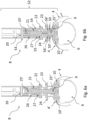
Fig. 4a and 4b show a mountingmember 8 attached to thebarrier 1, pivoted in an angle (Ω) with respect tobarrier 1. The mountingmember 8 is suitable for attachment of an extension device, using the extension device when installing the barrier into the sewage pipe, through a manhole or an inspection hole. The installation process of the barrier is made easier, when using a mountingmember 8 with pivotable mechanisms, to place the barrier into the position in the sewage pipe through for example a man-hole or an inspection hole. - The
barrier 1 extends along a longitudinal axis X. The mounting member 8 (mounting mechanism 52) is attached to theback part 5 of thebarrier 1, using a mounting joint 3. The mounting joint 3 comprises a pivot limiting arrangement comprising abar 18 extending from the centre mandrel (25). At the end of the bar (18) a flange (17) upstanding from the frame housing (9) is provided. In the flange (17) is provided a slit in which the movement of the bar (18) is limited, thereby limiting the tilt (and the angle Ω) of the central mandrel (25). -
Fig. 4a illustrates that thecentre mandrel 25 is connected inside the mountingmember 8 as an extension. Thecentre mandrel 25 is attached to theframe housing 9. Theguide plate 24 is attached to the mountingmember 8, and is in contact withflanges 19 provided on the wings (4, 4') where the upper edges (56, 56') are curved. An axis y is parallel to thecentre mandrel 25, extending through the centre of the mountingmember 8, and is perpendicular to the longitudinal axis X, in the cross section forming an angle Ω. -
Fig. 4b illustrates theguide plate 24, which is connected to the mountingmember 8 as an extension. Theguide plate 24 is in contact withflanges 19 provided on the wings (4, 4') where the upper edges (56, 56') of the flanges (19) are curved. The mountingmember 8 is moved to another position away from a position where the axis y is perpendicular to the longitudinal axis X, and the angle S2 is less than 90°. - The mounting
member 8 is moveable backwards and forwards within the limits of the slits in theflange 17, where theflange 17 determines the maximum variation of the angle S2. - The
flanges 19 may also have a semi-spherically shaped surface, where the moving joint 3, and therefore also the mountingmember 8, is allowed to move within a substantial angle Ω. The axis y is in relation to the longitudinal axis X, and forms the angle Ω. Thebar 18 is attached at one end to thecentre mandrel 25, and in an opposite end thebar 18 is retained in a slit in theflange 17, which limit the movement of the mountingmember 8, so that the angle S2 is within the predetermined limitations. -
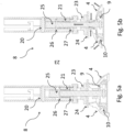
Fig. 5a and 5b show a mountingmember 8 attached to abarrier 1, for moving thewings 4 of thebarrier 1, when installing thebarrier 1 in a sewage pipe.Fig. 5a and fig. 5b is a cross-sectional view of the mountingmember 8 and thebarrier housing 2. The barrier infig. 5a is set in an installable position (i.e. the wings (4) are in a collapsed position), and the barrier infig. 5 b is in a fixed position when the barrier is installed in a sewage pipe (i.e. the wings are urged outwards into contact with the wall of the sewage pipe). - The mounting
mechanism 52 comprises as already mentioned above a mountingmember 8 which is in contact with theguide plate 24. Theguide plate 24 has an aperture through which the central mandrel passes such that the guide plate is mounted substantially concentrically around the central mandrel. On top of the guide plate is arranged a spring which is also concentrically mounted around the mandrel. Themandrel 25 is in an upper part provided with a threaded section which threaded sections correspond to a thread provided inside the mountingmember 8 such that the threaded section on the mountingmember 8 may be threaded onto the end of themandrel 25. - The mounting member comprises a concentrically arranged
cylindrical part 54 which when mounted in the mounting mechanism overlaps the guide plate a certain distance. In therotatable mounting member 53 is provided pins 22 which pins extend towards thecentral mandrel 25. The pins are arranged such that they engagelongitudinal slits 55 provided in the guide plate. Thelongitudinal slits 55 are provided parallel to the longitudinal direction of thecentral mandrel 25. - Turning back to
figure 5a thewings 4 are in a position where they are collapsed, i.e. where the diameter of the barrier is at a minimum such that the barrier is ready to be inserted into a sewage pipe. In this position therotable mounting member 53 has been unscrewed in the matching threads between thecentral mandrel 25 and therotatable mounting member 53. In this position thepins 22 have moved in theslits 55 to an upper position whereby theguide plate 24 is not being urged downwards towards theupstanding flanges 50, 50' of thewings 4. In this position thespring 21 is inactive. - After having inserted the barrier into the sewage pipe the mounting mechanism is activated, which is illustrated with respect to figure 5d. When activating the mounting mechanism the
rotatable mounting member 53 is rotated such that the matching threads between thecentral mandrel 25 and the rotatable mounting member causes the rotatable mounting member to move downwards towards theguide plate 24 and thewings 4. Thepins 22 will consequently travel downwards in thelongitudinal slits 55 provided in theguide plate 24. At the same time theguide plate 24 will engage theupstanding flanges 50, 50' of thewings 4 thereby urging the wings outwards as indicated by the arrows. Thewings 4 will pivot around thehinges 10 due to the increased pressure put on theupstanding flanges 50, 50'. Eventually, therotatable mounting member 53 will have compressed thespring 21 in a position where the pins are not urging the guide plate upwards or downwards, but where the pins are situated substantially free of the ends of thelongitudinal slits 55 provided in the guide plate. - At this position the
spring 21 is urging theguide plate 24 downwards into contact with theupstanding flanges 50, 50' such that thewings 4 are urged outwards. The movement of thewings 4 is limited by the sidewalls of the sewage pipe such that a counter pressure will arise against the downwards movement of theguide plate 24 urged downwards by the spring force arising from thespring 21. - Due to the fact that it is the
spring 21 that creates the force urging the wings into contact with the sides of the sewage pipe variations in temperature or other variations will be assimilated by thespring 21 in that the spring is compressed due to the downward force created by therotatable mounting member 53 engaging the thread on the free end of thecentral mandrel 25. - The support wings are pivotally attached to the
frame house 9, using wing hinges 10. The upper part of thesupport wings 10 are moveably in contact with aguide plate 24. Aplate base 23 is adjacent to the other side of theguide plate 24, opposite the side of the support wings. Theguide plate 24 and theplate base 23 have a centre aperture fitted such that thecentre mandrel 25 can pass through. Theguide plate 24 and theplate base 23 may be one unitary member. - A spring is placed inside the mounting
member 8. - In
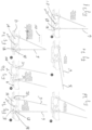
fig. 7a-7f is illustrated the construction of one shutter guide mechanism in various stages. In this embodiment, theshutter guide mechanism 7" is provided with apivotable member 81 which in a first end 81' is provided with a cut-out 83. In the position illustrated infig. 7a , the cut-outportion 83 is tilted downwards such that it is in contact with the upper end of thedownstream shutter 6. Apin 80 is provided which is also in engagement with the upper end of thedownstream shutter 6, such that thedownstream shutter 6 cannot pivot due to the mutual engagement of the upper end of the shutter between thepin 80 and the cut-outsection 83. The upstream shutter 6' is due to gravity pivoted such that the upper end of the upstream shutter 6' is urged against thepivotable member 81 whereby thepivotable locking member 81 is kept in the position where the cut-outsection 83 is engaging the upper end of thedownstream shutter 6. - In
fig. 7b is illustrated a situation where a vermin (not illustrated) is travelling against the flow direction 101. In this position thedownstream shutter 6 has engaged thecutback section 83 on thepivotable locking member 81 and the vermin can therefore not pivot the shutter and create passage pass the barrier. - In
fig. 7c is illustrated a situation where liquid flowing in the pipe system in which the barrier is mounted has pivoted the upstream shutter 6' such that it has released thepivotable locking member 81 which thereby rotates around itsaxle 15" whereby thecutback section 83 is elevated allowing the downstream shutter to pivot in one direction. In this situation the pivotable movement of thedownstream shutter 6 is only blocked by thepin 80. Consequently, it is possible as illustrated infig. 7d for bothshutters 6, 6' to pivot and thereby allow liquid and any solids suspended in the liquid to pass in a downstream direction. Illustrated infigure 7e is a situation where bothshutters 6, 6' are pivoted into their max open position whereby the entire barrier only blocks a very small part of the flow area through the pipe system. - Once the liquid flow subsides, the
shutters 6, 6' will due to gravity pivot back into a position as illustrated infigure 7f . In this position thedownstream shutter 6 is blocked for further pivotable movement by thepin 80 and at the same time the upstream shutter 6' is engaging the engagement surface 82 on the second end of thepivotable locking member 81 whereby the pivotable locking member will be pivoted about itsaxle 15" such that the cut-outsection 83 will engage the upper end of thedownstream shutter 6 as illustrated with reference tofig. 7a . - The entire
shutter guide mechanism 7" is mounted in a mountingbody 100 which in return is mounted in an aperture provided in thehousing 9 in such a way that the mounting body may be removed or turned 180 degrees relative to the flow direction whereby the shutters will be able to be blocked or opened in a opposite direction relative to thehousing 9. - Turning to
fig. 8a-8g , a further embodiment of a shutter guide mechanism 7' will be explained. In this embodiment two pins 60", 60‴ are provided such that theshutters 6, 6' when pivoting in the upside direction will have their upper ends of theshutter 6, 6' engage the pins 60", 60‴ such that further pivotable movement is arrested. The shutter, like is the case with the other embodiments, pivot aroundaxles 15. In this embodiment apivotable locking member 70 pivots about an axle 15' in order to carry out its locking action. In the position illustrated infig. 8a , both shutters are blocked such that they cannot pivot in an upstream direction and thedownstream shutter 6 is by a cut-out section 83' provided in a first end 70' of thepivotable locking member 70 arrested against pivoting in the downstream direction. In this manner, a vermin trying to pivot theshutter 6 will not be able to pivot this shutter as the upper end of the shutter is blocked for any pivotable moment. - Turning to
fig. 8b , a situation where a downstream flow of liquid in the pipe system urges the upstream shutter 6' to pivot slightly is illustrated. As the water flow 101 urges the upstream shutter 6' to pivot, the upper end of the upstream shutter 6' will slide along the sliding surface 71. As the distance between the centre of the shutter'saxle 15 and the sliding surface decreases, the pivotable locking member will be urged to pivot around its axle 15'. When the upstream shutter 6' has pivoted into a position illustrated with reference tofig. 8c , thepivotable member 70 has been forced by the upper end of the upstream shutter 6' sliding along the sliding surface 71 to be pivoted sufficiently such that the engagement surface 72 of thecutback section 83 has released the upper end of the downstream shutter 6' such that the downstream shutter in this position may pivot influenced by the liquid flow in the pipe. This is illustrated infigures 8d and 8e where it is clear that thedownstream shutter 6 can pivot unhampered by thepivotable locking member 70 thereby allowing liquid to flow pass the barrier. Infig. 8e is illustrated a situation where maximum liquid flow in the pipe system has caused both shutters to be in their max. pivotable position. In this position thepivotable locking member 70 has pivoted into its lowermost position where it is not engaging any of the upper ends of theshutter 6, 6'. - As the water flow subsides, the shutters will due to gravity pivot back towards an upright position. During this movement the upstream shutter 6' will again engage the sliding face 71 of the
pivotable member 70 thereby pivoting thepivotable locking member 70 upwards allowing both shutters to attain an upright position as illustrated with reference tofig. 8g which is identical tofig. 8a . In this position thepivotable locking member 70 has again reached the position where the engagement surface of the cutback section 83' is engaging the downstream shutter as explained above thereby blocking the downstream shutter's 6 pivotable motion. - As was the case with the locking arrangement explained above with reference to
fig. 7a-7f , the shutter guide mechanism 7' illustrated with reference tofigures 8a-8g may also be arranged in a separate mounting body which, as was the case with the embodiment in the invention described with reference tofig. 7a - 7f , may be removed or replaced or turned around relative to the housing of the barrier.
Claims (7)
- Barrier suitable to be mounted in a pipe system, in particular a sewage pipe in order to hinder rodents and vermin to be able to pass the barrier (1) in the upstream direction, where said barrier (1) comprises:- two support wings (4,4') pivotably mounted on a housing (9), where means are provided for mechanically urging each wing (4,4') away or towards the other wing (4,4'), such that in use when the barrier is mounted in a pipe system such that the housing's (9) longitudinal axis (X) is parallel to the longitudinal axis of the pipe, the wings (4,4') may be brought into contact with the inner side of a pipe in the pipe system;- two shutters (6,6')) suspended from said housing (9) the shutters (6,6') being arranged for pivotal movement around axles (15) arranged perpendicular to the longitudinal axis (X), such that the shutters in a first position substantially barricade the pipe in which the barrier is mounted, and in a second position are pivoted into a position where only an upper section of the pipe is blocked.characterised in thata pivotal locking member (70, 81) is provided, said locking member (70, 81) pivots around an axle (15') parallel to the axles (15), wherein the locking member (70, 81) has a first sliding face (71) adjacent a distal end of the, in use upstream shutter (6') which in use extends above the axles (15) towards the housing (9),wherein, as the upstream shutter (6') pivots, the upstream shutter's (6') engagement with the sliding surface will cause the locking member (70, 81) to pivot, wherein the locking member (70, 81) further comprises an engagement surface (72), which engagement surface (72) in a first position blocks the pivotal movement of the, in use downstream shutter (6), and in a second position, said locking member, and thereby the engagement surface (72) is pivoted by the upstream shutter (6') sliding along the sliding surface into a position allowing the downstream shutter (6) to pivot freely relative to the engagement surface (72) and as the shutters (6, 6') pivot back, the locking member (70, 81) is lifted and allows the shutters (6, 6') back into the first position, wherein the locking member pivots back into locking engagement with the downstream shutter (6) orwherein the pivotal locking member (70, 81) is arranged for pivotal movement around an axle (15"), said axle (15") being parallel to the axles (15) around which the shutters (6, 6') pivot, wherein said locking member (70, 81) in a first end (81') adjacent the downstream shutter (6) is provided with a cutback (83) adapted to engage the uppermost part of the in use downstream shutter (6), and in an opposite second end is provided with a sliding surface (82), such that as the in use upstream shutter (6') due to the influence of gravity pivots, the upper end of the upstream shutter (6') will urge the locking member (70, 81) to pivot, whereby the cutback (83) of the locking member (70, 81) will engage the upper end of the in use downstream shutter (6), thereby blocking for further pivotal movement, where the locking member (70, 81) when not urged by the in use upstream shutter (6') will pivot such that the cutback (83) disengages the end of the in use downstream shutter (6).
- Barrier according to claim 1, where the means provided for mechanically urging each wing (4,4') away or towards the other wing (4,4'), comprises a central mandrel (25) having a longitudinal axis (Y), which central mandrel (25) in a first end is pivotably attached to the housing (9), such that the central mandrel (25) may be rotated around the central mandrels longitudinal axis (Y), and where in a second end of the central mandrel a thread is provided,- and further that between the first and second ends of the central mandrel a guide plate (24) is concentrically mounted, such that the guide plate (24) in one end is able to come into contact with an upper edge (56,56') of the upstanding flanges (50,50') of the wings (4,4') and in the opposite end is in contact with a spring (21) concentrically arranged around the central mandrel (25),- where said spring (21) in the end, not in contact with the guide plate (24) may be in contact with a rotatable mounting member (53), said mounting member (53) having a central aperture with a corresponding thread such that the mounting member may be threaded onto the second end of the central mandrel (25), and thereby compress or release the spring (21), where the mounting member (53) further comprises a concentrically arranged cylindrical part (54) partly overlapping part of the guide plate (24), and where guide pins (22) mounted in the cylindrical part (54) extends into grooves (55) in the guide plate (24), said grooves (55) are provided parallel to the longitudinal direction of the central mandrel (25).
- Barrier according to claim 2, wherein the central mandrel (25) may be tilted relative to the housing (9) in a direction parallel to the housing's longitudinal axis (x), and where upper edges (56,56') of the upstanding flanges (50,50') are curved in a direction parallel to the longitudinal axis (x).
- Barrier according to any of claims 1 to 3, where said shutters (6) are mounted in a shutter guide mechanism (7), which mechanism is capable of adjusting and/or controlling the shutters' pivotal movement along the housing's longitudinal axis (x), where the shutters (6) are arranged for pivotal movement around axles (15) arranged perpendicular to the longitudinal axis (x), such that part of the shutter (6) in use extends above the axles (15) towards the housing (9) where said shutter guide mechanism is arranged in the housing (9), where a moveable guide part (12) is displaceable in the direction of the longitudinal axis (x), where said moveable guide part (12) is arranged above the housing (9), and where the moveable guide part has two downwards projecting pins (60,60'), said projecting pins (60,60') projecting through a longitudinal slit (61) in the housing (9) such that the projecting pins (60,60') may interfere with the pivotal movement of the part of the shutters (6) extending above the axles (15), thereby adjusting the shutters' pivotal movement along the housing's longitudinal axis (x) .
- Barrier according to any of claims 1 to 3, where said shutters (6) are mounted in a shutter guide mechanism (7'), which mechanism is capable of controlling the shutters' pivotal movement along the housing's longitudinal axis (x), where the shutters (6) are arranged for pivotal movement around axles (15) arranged perpendicular to the longitudinal axis (x), such that part of the shutter (6) in use extends above the axles (15) towards the housing (9) where said shutter guide mechanism is arranged either integrally with the housing or is attached to the housing (9), where said shutter guide mechanism (7') has two downwards projecting pins (60",60‴), such that the projecting pins (60,60') may interfere and halt the pivotal movement of the part of the shutters (6) extending above the axles (15) in a first pivotal direction.
- Barrier according to any of claims 4 or 5 where said shutter guide mechanism (7) is a separate part, said part having a mounting body, where the housing of the barrier has an aperture suitable to receive and retain said mounting body, and where said mounting body may be arranged in the aperture in two opposite directions, thereby allowing the shutters to operate in two opposite directions.
- Barrier according to any preceding claim wherein at least one shutter (6, 6') is provided with pointed tips extending out from and along at least part of the shutter's perimeter.
Applications Claiming Priority (3)
| Application Number | Priority Date | Filing Date | Title |
|---|---|---|---|
| DKPA201770752A DK179851B1 (en) | 2017-10-03 | 2017-10-03 | Barrier suitable for installation in a sewage pipe |
| DKPA201870096 | 2018-02-16 | ||
| PCT/DK2018/050248 WO2019068301A1 (en) | 2017-10-03 | 2018-10-02 | Rat and vermin barrier suitable for installation in a sewage pipe |
Publications (3)
| Publication Number | Publication Date |
|---|---|
| EP3692219A1 EP3692219A1 (en) | 2020-08-12 |
| EP3692219C0 EP3692219C0 (en) | 2023-06-07 |
| EP3692219B1 true EP3692219B1 (en) | 2023-06-07 |
Family
ID=63832161
Family Applications (1)
| Application Number | Title | Priority Date | Filing Date |
|---|---|---|---|
| EP18785250.4A Active EP3692219B1 (en) | 2017-10-03 | 2018-10-02 | Rat and vermin barrier suitable for installation in a sewage pipe |
Country Status (7)
| Country | Link |
|---|---|
| US (1) | US11470838B2 (en) |
| EP (1) | EP3692219B1 (en) |
| JP (1) | JP2020536189A (en) |
| BR (1) | BR112020006685A2 (en) |
| CA (1) | CA3113752A1 (en) |
| ES (1) | ES2949614T3 (en) |
| WO (1) | WO2019068301A1 (en) |
Families Citing this family (6)
| Publication number | Priority date | Publication date | Assignee | Title |
|---|---|---|---|---|
| US11320057B2 (en) * | 2019-02-05 | 2022-05-03 | Reseau Drain Corp. | Anti-rat valve and flap therefor |
| EP3739136B1 (en) | 2019-05-15 | 2025-08-20 | Nordisk Innovation ApS | Vermin barrier with locking mechanism |
| US12044000B2 (en) * | 2021-02-09 | 2024-07-23 | Denis Friezner | Method and apparatus for controlling hazardous materials disposed within a storm water control system |
| EP4086399B1 (en) * | 2021-05-03 | 2024-09-25 | Nordisk Innovation ApS | A barrier for installation in a sewage system with limited space |
| USD1073852S1 (en) * | 2022-08-25 | 2025-05-06 | Reseau Drain Corp. | Anti-rat flap |
| EP4491814A1 (en) * | 2023-07-12 | 2025-01-15 | Ratstop Limited | An apparatus for preventing the movement of rats in a pipe |
Family Cites Families (7)
| Publication number | Priority date | Publication date | Assignee | Title |
|---|---|---|---|---|
| US3118469A (en) * | 1961-12-01 | 1964-01-21 | John O Schliesser | Animal guard for tile drain pipe |
| DK1826326T3 (en) | 2006-02-27 | 2011-05-09 | Nordisk Innovation Aps | Barrier for preventing rats or other pests from entering a sewer system |
| EP2113615B1 (en) * | 2008-03-05 | 2011-05-04 | Nordisk Innovation ApS | Two-way barrier for preventing rats or other vermin from entering a sewage pipe system |
| EP2868823B1 (en) * | 2013-10-31 | 2018-12-05 | Nordisk Innovation ApS | Vermin barrier and method of operating said vermin barrier |
| EP2933392B1 (en) * | 2014-04-16 | 2020-06-10 | Nordisk Innovation ApS | Rat barrier with smooth and toothed shutters |
| GB2537093B (en) * | 2015-02-23 | 2018-01-03 | Mcalpine & Co Ltd | Improved anti-vermin barrier |
| EP3739136B1 (en) * | 2019-05-15 | 2025-08-20 | Nordisk Innovation ApS | Vermin barrier with locking mechanism |
-
2018
- 2018-10-02 EP EP18785250.4A patent/EP3692219B1/en active Active
- 2018-10-02 ES ES18785250T patent/ES2949614T3/en active Active
- 2018-10-02 WO PCT/DK2018/050248 patent/WO2019068301A1/en not_active Ceased
- 2018-10-02 US US16/753,323 patent/US11470838B2/en active Active
- 2018-10-02 CA CA3113752A patent/CA3113752A1/en active Pending
- 2018-10-02 JP JP2020520067A patent/JP2020536189A/en active Pending
- 2018-10-02 BR BR112020006685-0A patent/BR112020006685A2/en not_active Application Discontinuation
Also Published As
| Publication number | Publication date |
|---|---|
| EP3692219A1 (en) | 2020-08-12 |
| US20200236922A1 (en) | 2020-07-30 |
| BR112020006685A2 (en) | 2020-09-24 |
| US11470838B2 (en) | 2022-10-18 |
| WO2019068301A1 (en) | 2019-04-11 |
| JP2020536189A (en) | 2020-12-10 |
| CA3113752A1 (en) | 2019-04-11 |
| EP3692219C0 (en) | 2023-06-07 |
| WO2019068301A9 (en) | 2019-11-07 |
| ES2949614T3 (en) | 2023-10-02 |
Similar Documents
| Publication | Publication Date | Title |
|---|---|---|
| US11470838B2 (en) | Rat and vermin barrier suitable for installation in a sewage pipe | |
| EP2113615B1 (en) | Two-way barrier for preventing rats or other vermin from entering a sewage pipe system | |
| DE69828978T2 (en) | Device for collecting solids from a liquid | |
| US20120273050A1 (en) | Automatic Shutoff Drain | |
| KR20190004251A (en) | Grating with smell interception function | |
| EP0569722B1 (en) | Assembly ring | |
| EP1826326B1 (en) | Barrier for preventing rats or other vermin from entering a sewage pipe system | |
| DK179851B1 (en) | Barrier suitable for installation in a sewage pipe | |
| DE102015121874A1 (en) | Drainage device for rainwater | |
| EP3739136B1 (en) | Vermin barrier with locking mechanism | |
| WO1988008471A1 (en) | Back flow blocker in sloping pipes | |
| KR100884730B1 (en) | Odor backflow prevention device | |
| DK2800838T3 (en) | Safety mechanism for a pest deterrent device | |
| AU2022219939B2 (en) | Cleanout conduit valve assemblies and installations | |
| DE4204344C3 (en) | Water meter mounting and installation device | |
| KR101967801B1 (en) | Functional Grating | |
| EP1069252B1 (en) | Flow regulating device for rainwater retention basin | |
| JP2024099399A (en) | Backflow prevention devices and catch basins equipped with backflow prevention devices | |
| EP1811091A1 (en) | Support Apparatus | |
| EP2241689B1 (en) | Mounting assembly with supporting bracket for mounting a water treatment unit in a water reservoir | |
| US913554A (en) | Automatic tank-valve. | |
| EP2573285B1 (en) | Waste water hoisting facility | |
| DE69728021T2 (en) | Device for controlling a drain valve of a cistern | |
| DE29807337U1 (en) | Drainage control device for rainwater retention basins | |
| KR101137544B1 (en) | Preventing device for rainwater inflow |
Legal Events
| Date | Code | Title | Description |
|---|---|---|---|
| STAA | Information on the status of an ep patent application or granted ep patent |
Free format text: STATUS: UNKNOWN |
|
| STAA | Information on the status of an ep patent application or granted ep patent |
Free format text: STATUS: THE INTERNATIONAL PUBLICATION HAS BEEN MADE |
|
| PUAI | Public reference made under article 153(3) epc to a published international application that has entered the european phase |
Free format text: ORIGINAL CODE: 0009012 |
|
| STAA | Information on the status of an ep patent application or granted ep patent |
Free format text: STATUS: REQUEST FOR EXAMINATION WAS MADE |
|
| 17P | Request for examination filed |
Effective date: 20200420 |
|
| AK | Designated contracting states |
Kind code of ref document: A1 Designated state(s): AL AT BE BG CH CY CZ DE DK EE ES FI FR GB GR HR HU IE IS IT LI LT LU LV MC MK MT NL NO PL PT RO RS SE SI SK SM TR |
|
| AX | Request for extension of the european patent |
Extension state: BA ME |
|
| DAV | Request for validation of the european patent (deleted) | ||
| DAX | Request for extension of the european patent (deleted) | ||
| GRAP | Despatch of communication of intention to grant a patent |
Free format text: ORIGINAL CODE: EPIDOSNIGR1 |
|
| STAA | Information on the status of an ep patent application or granted ep patent |
Free format text: STATUS: GRANT OF PATENT IS INTENDED |
|
| INTG | Intention to grant announced |
Effective date: 20220530 |
|
| GRAJ | Information related to disapproval of communication of intention to grant by the applicant or resumption of examination proceedings by the epo deleted |
Free format text: ORIGINAL CODE: EPIDOSDIGR1 |
|
| STAA | Information on the status of an ep patent application or granted ep patent |
Free format text: STATUS: REQUEST FOR EXAMINATION WAS MADE |
|
| GRAP | Despatch of communication of intention to grant a patent |
Free format text: ORIGINAL CODE: EPIDOSNIGR1 |
|
| STAA | Information on the status of an ep patent application or granted ep patent |
Free format text: STATUS: GRANT OF PATENT IS INTENDED |
|
| INTC | Intention to grant announced (deleted) | ||
| INTG | Intention to grant announced |
Effective date: 20221104 |
|
| GRAS | Grant fee paid |
Free format text: ORIGINAL CODE: EPIDOSNIGR3 |
|
| GRAA | (expected) grant |
Free format text: ORIGINAL CODE: 0009210 |
|
| STAA | Information on the status of an ep patent application or granted ep patent |
Free format text: STATUS: THE PATENT HAS BEEN GRANTED |
|
| AK | Designated contracting states |
Kind code of ref document: B1 Designated state(s): AL AT BE BG CH CY CZ DE DK EE ES FI FR GB GR HR HU IE IS IT LI LT LU LV MC MK MT NL NO PL PT RO RS SE SI SK SM TR |
|
| REG | Reference to a national code |
Ref country code: GB Ref legal event code: FG4D |
|
| REG | Reference to a national code |
Ref country code: CH Ref legal event code: EP Ref country code: AT Ref legal event code: REF Ref document number: 1575413 Country of ref document: AT Kind code of ref document: T Effective date: 20230615 Ref country code: DE Ref legal event code: R096 Ref document number: 602018051244 Country of ref document: DE |
|
| U01 | Request for unitary effect filed |
Effective date: 20230704 |
|
| U07 | Unitary effect registered |
Designated state(s): AT BE BG DE DK EE FI FR IT LT LU LV MT NL PT SE SI Effective date: 20230712 |
|
| REG | Reference to a national code |
Ref country code: LT Ref legal event code: MG9D |
|
| REG | Reference to a national code |
Ref country code: ES Ref legal event code: FG2A Ref document number: 2949614 Country of ref document: ES Kind code of ref document: T3 Effective date: 20231002 |
|
| PG25 | Lapsed in a contracting state [announced via postgrant information from national office to epo] |
Ref country code: NO Free format text: LAPSE BECAUSE OF FAILURE TO SUBMIT A TRANSLATION OF THE DESCRIPTION OR TO PAY THE FEE WITHIN THE PRESCRIBED TIME-LIMIT Effective date: 20230907 |
|
| PG25 | Lapsed in a contracting state [announced via postgrant information from national office to epo] |
Ref country code: RS Free format text: LAPSE BECAUSE OF FAILURE TO SUBMIT A TRANSLATION OF THE DESCRIPTION OR TO PAY THE FEE WITHIN THE PRESCRIBED TIME-LIMIT Effective date: 20230607 Ref country code: HR Free format text: LAPSE BECAUSE OF FAILURE TO SUBMIT A TRANSLATION OF THE DESCRIPTION OR TO PAY THE FEE WITHIN THE PRESCRIBED TIME-LIMIT Effective date: 20230607 Ref country code: GR Free format text: LAPSE BECAUSE OF FAILURE TO SUBMIT A TRANSLATION OF THE DESCRIPTION OR TO PAY THE FEE WITHIN THE PRESCRIBED TIME-LIMIT Effective date: 20230908 |
|
| U20 | Renewal fee for the european patent with unitary effect paid |
Year of fee payment: 6 Effective date: 20231026 |
|
| PG25 | Lapsed in a contracting state [announced via postgrant information from national office to epo] |
Ref country code: SK Free format text: LAPSE BECAUSE OF FAILURE TO SUBMIT A TRANSLATION OF THE DESCRIPTION OR TO PAY THE FEE WITHIN THE PRESCRIBED TIME-LIMIT Effective date: 20230607 |
|
| PG25 | Lapsed in a contracting state [announced via postgrant information from national office to epo] |
Ref country code: IS Free format text: LAPSE BECAUSE OF FAILURE TO SUBMIT A TRANSLATION OF THE DESCRIPTION OR TO PAY THE FEE WITHIN THE PRESCRIBED TIME-LIMIT Effective date: 20231007 |
|
| PG25 | Lapsed in a contracting state [announced via postgrant information from national office to epo] |
Ref country code: SM Free format text: LAPSE BECAUSE OF FAILURE TO SUBMIT A TRANSLATION OF THE DESCRIPTION OR TO PAY THE FEE WITHIN THE PRESCRIBED TIME-LIMIT Effective date: 20230607 Ref country code: SK Free format text: LAPSE BECAUSE OF FAILURE TO SUBMIT A TRANSLATION OF THE DESCRIPTION OR TO PAY THE FEE WITHIN THE PRESCRIBED TIME-LIMIT Effective date: 20230607 Ref country code: RO Free format text: LAPSE BECAUSE OF FAILURE TO SUBMIT A TRANSLATION OF THE DESCRIPTION OR TO PAY THE FEE WITHIN THE PRESCRIBED TIME-LIMIT Effective date: 20230607 Ref country code: IS Free format text: LAPSE BECAUSE OF FAILURE TO SUBMIT A TRANSLATION OF THE DESCRIPTION OR TO PAY THE FEE WITHIN THE PRESCRIBED TIME-LIMIT Effective date: 20231007 Ref country code: CZ Free format text: LAPSE BECAUSE OF FAILURE TO SUBMIT A TRANSLATION OF THE DESCRIPTION OR TO PAY THE FEE WITHIN THE PRESCRIBED TIME-LIMIT Effective date: 20230607 |
|
| PG25 | Lapsed in a contracting state [announced via postgrant information from national office to epo] |
Ref country code: PL Free format text: LAPSE BECAUSE OF FAILURE TO SUBMIT A TRANSLATION OF THE DESCRIPTION OR TO PAY THE FEE WITHIN THE PRESCRIBED TIME-LIMIT Effective date: 20230607 |
|
| REG | Reference to a national code |
Ref country code: DE Ref legal event code: R097 Ref document number: 602018051244 Country of ref document: DE |
|
| PLBE | No opposition filed within time limit |
Free format text: ORIGINAL CODE: 0009261 |
|
| STAA | Information on the status of an ep patent application or granted ep patent |
Free format text: STATUS: NO OPPOSITION FILED WITHIN TIME LIMIT |
|
| 26N | No opposition filed |
Effective date: 20240308 |
|
| PG25 | Lapsed in a contracting state [announced via postgrant information from national office to epo] |
Ref country code: MC Free format text: LAPSE BECAUSE OF FAILURE TO SUBMIT A TRANSLATION OF THE DESCRIPTION OR TO PAY THE FEE WITHIN THE PRESCRIBED TIME-LIMIT Effective date: 20230607 |
|
| REG | Reference to a national code |
Ref country code: CH Ref legal event code: PL |
|
| PG25 | Lapsed in a contracting state [announced via postgrant information from national office to epo] |
Ref country code: CH Free format text: LAPSE BECAUSE OF NON-PAYMENT OF DUE FEES Effective date: 20231031 |
|
| PG25 | Lapsed in a contracting state [announced via postgrant information from national office to epo] |
Ref country code: CH Free format text: LAPSE BECAUSE OF NON-PAYMENT OF DUE FEES Effective date: 20231031 |
|
| PG25 | Lapsed in a contracting state [announced via postgrant information from national office to epo] |
Ref country code: IE Free format text: LAPSE BECAUSE OF NON-PAYMENT OF DUE FEES Effective date: 20231002 |
|
| PG25 | Lapsed in a contracting state [announced via postgrant information from national office to epo] |
Ref country code: IE Free format text: LAPSE BECAUSE OF NON-PAYMENT OF DUE FEES Effective date: 20231002 |
|
| U20 | Renewal fee for the european patent with unitary effect paid |
Year of fee payment: 7 Effective date: 20241025 |
|
| PG25 | Lapsed in a contracting state [announced via postgrant information from national office to epo] |
Ref country code: CY Free format text: LAPSE BECAUSE OF FAILURE TO SUBMIT A TRANSLATION OF THE DESCRIPTION OR TO PAY THE FEE WITHIN THE PRESCRIBED TIME-LIMIT; INVALID AB INITIO Effective date: 20181002 |
|
| PG25 | Lapsed in a contracting state [announced via postgrant information from national office to epo] |
Ref country code: HU Free format text: LAPSE BECAUSE OF FAILURE TO SUBMIT A TRANSLATION OF THE DESCRIPTION OR TO PAY THE FEE WITHIN THE PRESCRIBED TIME-LIMIT; INVALID AB INITIO Effective date: 20181002 |
|
| U20 | Renewal fee for the european patent with unitary effect paid |
Year of fee payment: 8 Effective date: 20251027 |
|
| PG25 | Lapsed in a contracting state [announced via postgrant information from national office to epo] |
Ref country code: TR Free format text: LAPSE BECAUSE OF FAILURE TO SUBMIT A TRANSLATION OF THE DESCRIPTION OR TO PAY THE FEE WITHIN THE PRESCRIBED TIME-LIMIT Effective date: 20230607 |
|
| PGFP | Annual fee paid to national office [announced via postgrant information from national office to epo] |
Ref country code: GB Payment date: 20251024 Year of fee payment: 8 |
|
| PGFP | Annual fee paid to national office [announced via postgrant information from national office to epo] |
Ref country code: ES Payment date: 20251114 Year of fee payment: 8 |