EP3691761B1 - A vertical roulette mechanism - Google Patents
A vertical roulette mechanism Download PDFInfo
- Publication number
- EP3691761B1 EP3691761B1 EP18864558.4A EP18864558A EP3691761B1 EP 3691761 B1 EP3691761 B1 EP 3691761B1 EP 18864558 A EP18864558 A EP 18864558A EP 3691761 B1 EP3691761 B1 EP 3691761B1
- Authority
- EP
- European Patent Office
- Prior art keywords
- roulette
- wheel
- vertical
- recited
- stand
- Prior art date
- Legal status (The legal status is an assumption and is not a legal conclusion. Google has not performed a legal analysis and makes no representation as to the accuracy of the status listed.)
- Active
Links
Images


Classifications
-
- G—PHYSICS
- G07—CHECKING-DEVICES
- G07F—COIN-FREED OR LIKE APPARATUS
- G07F17/00—Coin-freed apparatus for hiring articles; Coin-freed facilities or services
- G07F17/32—Coin-freed apparatus for hiring articles; Coin-freed facilities or services for games, toys, sports, or amusements
- G07F17/3202—Hardware aspects of a gaming system, e.g. components, construction, architecture thereof
- G07F17/3204—Player-machine interfaces
- G07F17/3211—Display means
-
- A—HUMAN NECESSITIES
- A63—SPORTS; GAMES; AMUSEMENTS
- A63F—CARD, BOARD, OR ROULETTE GAMES; INDOOR GAMES USING SMALL MOVING PLAYING BODIES; VIDEO GAMES; GAMES NOT OTHERWISE PROVIDED FOR
- A63F5/00—Roulette games
-
- G—PHYSICS
- G07—CHECKING-DEVICES
- G07F—COIN-FREED OR LIKE APPARATUS
- G07F17/00—Coin-freed apparatus for hiring articles; Coin-freed facilities or services
- G07F17/32—Coin-freed apparatus for hiring articles; Coin-freed facilities or services for games, toys, sports, or amusements
- G07F17/3202—Hardware aspects of a gaming system, e.g. components, construction, architecture thereof
- G07F17/3204—Player-machine interfaces
- G07F17/3209—Input means, e.g. buttons, touch screen
-
- G—PHYSICS
- G07—CHECKING-DEVICES
- G07F—COIN-FREED OR LIKE APPARATUS
- G07F17/00—Coin-freed apparatus for hiring articles; Coin-freed facilities or services
- G07F17/32—Coin-freed apparatus for hiring articles; Coin-freed facilities or services for games, toys, sports, or amusements
- G07F17/3202—Hardware aspects of a gaming system, e.g. components, construction, architecture thereof
- G07F17/3216—Construction aspects of a gaming system, e.g. housing, seats, ergonomic aspects
-
- G—PHYSICS
- G07—CHECKING-DEVICES
- G07F—COIN-FREED OR LIKE APPARATUS
- G07F17/00—Coin-freed apparatus for hiring articles; Coin-freed facilities or services
- G07F17/32—Coin-freed apparatus for hiring articles; Coin-freed facilities or services for games, toys, sports, or amusements
- G07F17/3286—Type of games
- G07F17/3288—Betting, e.g. on live events, bookmaking
Definitions
- US 2010/120488 A1 discloses a gamble wheel assembly for use in an amusement or gaming machine comprising a gamble wheel rotatably mounted with respect to a stationary support about an axis inclined at an acute angle or at a right angle to the vertical, the wheel being formed with a plurality of circumferentially arranged ball carrying pockets, so arranged that when a ball is in a pocket at least part of the ball is visible from the front side of the wheel, a part-annular ball retainer mounted on the support and so arranged to extend circumferentially about the wheel axis adjacent to the pockets to retain captive a ball that has been captured in a pocket in a ball capture region of the rotational path of the pockets, a ball supply unit mounted on said support and so arranged so as to deliver a ball to the wheel, the arrangement being such that the delivered ball is fed directly or indirectly to said ball capture region for capture in a pocket, controllable release means for releasing a captured ball from the pockets, and ball outlet means for receiving balls released from the pockets.
- the present disclosure relates generally, but not exclusively, to the field of gaming, particularly gaming cabinets for different games, including roulette.
- An embodiment is directed to a single player vertical roulette mechanism that includes a stand, a wheel and a motor, as defined in claim 1.
- Some embodiments of the present invention are described herein in terms of a gaming cabinets for particular games for illustrative purposes. However, embodiments of the present invention are not limited to just the types of games described and may be implemented in various wagering systems - both automated and manual - that provide similar functionalities.
- Figure 1 illustrates a base 100 for a universal cabinet for a variety of different games that may be connected to a top 101 of an upper section 102 of the base 100.
- the base 100 may further include a lower section 103 on which the upper section rests.
- the base 100 may include a number of exterior elements that provide visual and audio effects that serve to either attract attention to the game, so as to entice someone passing by to play a game offered by the universal cabinet, or to enhance the play of a game being played in the universal cabinet.
- the exterior elements may include soft touch gel buttons, such as buttons 104 and 106, gel arm rests 108 at the bottom of the upper section 102 where a players arms would rest for extended periods of time, and a control button 110 that may be used for different games.
- Other lighting effects that may be provided include gel LED modules 112 of different sizes and shapes and an ambient LED 114 that illuminates the bottom section 103 from underneath the upper section 102.
- the upper section 102 may further include a money/credit/card receiving/payout mechanism 116 and a display 118.
- Speakers 120 in the lower section 103 may provide some or all of the sound, depending on the nature of the game being played.
- a foot rest 122 may also be built into the lower section 102.
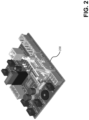
- the inside of the universal cabinet may include a controller module 200 that may provide common connections for each of the different types of toppers and provide a USB connection to an embedded computer (not shown) in the bottom section 103.
- the embedded computer may be a GANLOT AMDY-7005, which is designed for gaming applications.
- the controller module 200 may also provide outputs for the base cabinet lighting and buttons, which makes it possible to offer numerous gaming machine lighting designs.
- the controller module 200 may also make it possible to quickly change toppers on the base 100. Only the upper section 102 may need to be removed to access the controller module 200. Connections from the existing topper may be disconnected and the topper removed from the upper section 102. The new topper may then be attached to the upper section 102 and its connections plugged into the controller module 200.
- a switch in the controller module 200 may then be switched to correspond to the new topper.
- the new topper can be identified by connecting or plugging one or more additional modules for that topper into the controller module 200 or changing a program of the embedded computer. This may make it possible to quickly change the type of game that is being played on the universal cabinet base 100 without have to remove the base 100 from any row it is in and without moving other machines or forcing the other machines to be shut down. The may also make it possible to prototype and develop other toppers for new games, further reducing development and production costs.
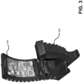
- Figure 3 and Figure 4 further illustrate the base 100 of the universal cabinet when a seat 300 and a tall curved display topper 302 have been connected.
- the seat 300 may include additional speakers 402, such as two 25 Watt/8 Ohm speakers in an upper section 403 of the seat 300. Additional speakers may be included in the topper 302, such as two 25 Watt/8 Ohm speakers 408 at the top of the topper 302 and two 25 Watt/8 Ohm speakers 410 at the bottom of the topper 302.
- a 50 Watt/4 Ohm rumble speaker 404 may be provided in the bottom section 405 of the seat 300. This many speakers may enable a variety of audio effects, especially if a range of speaker types are used, including tweeters, midranges and subwoofers or woofers.
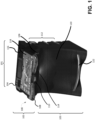
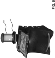
- Figure 5 , Figure 6 , Figure 7 and Figure 8 illustrate different types of topper that may be added to the base 100 as previously discussed. These toppers include the dice topper 500 of Figure 5 , which enables craps and similar types of dice games to be played.
- the base 100 includes a random generator (not shown) for controlling the randomness of the dice roll in order to make game fair. Even though the dice are being tossed as part of the game in the see-through section 502 of the dice topper 500, the game cycle speed may be just as fast as slot machine game cycles, thereby providing a different and more exciting form of a game with at least the same revenue potential as a slot machine being played for the same period of time.
- the base 100 may send random results for the game to the topper and in other cases the topper may send the random results to the bottom.
- the resulting throw of the dice may be randomly effected by a random generator in the base, but the resulting throw cannot be predetermined so it has to be determined at the topper and then sent to the base 100.
- Figure 6 illustrates to card game toppers, a baccarat topper 602 and a blackjack topper 604.
- Each of the card mechanism 606, such as a SUZO card flipper module may flip cards under control of the random generator.
- the card decks can be varied depending on the game, such as a classic deck with or without jokers, and cards including the back sides of cards so cards can be covered.
- Figure 7 illustrates a display card topper 700 where the display is wider than tall, which may allow higher resolution display.
- Figure 8 illustrates two different versions of vertical roulette toppers 802 and 808.
- Vertical roulette topper 802 includes a roulette wheel 804 and signage 806 on top of the roulette wheel 804, while vertical roulette topper 808 includes an additional display 808 on top of which is mounted a roulette wheel 812 and signage 814.
- the vertical roulette wheel 900 includes a stationary roulette ball 902, which is shown mounted to a non-moving portion of the wheel 900 near the top, although other positions are possible. Since the roulette ball 902 does not move, the numbers do, which is accomplished by mounting a circular ring of numbers on a transparent or translucent number wheel 904 that is rotated based on the random generator of the base 100. To simplify the electro-mechanics associated with rotating the number wheel 904, the number wheel 904 is sufficiently translucent that LED lighting 906 provided behind the numbers is clearly visible.
- the LED lighting 906 circuit board is illustrated in Figure 10 .
- the numbers themselves may be physically printed or attached to the number wheel so they can be illuminated by the LED lighting 906.
- the random generator determines an amount of force to be applied to rotate number wheel 906 or the random generator determines when a breaking force will be applied to the number wheel 906 or a combination of both.
- FIG. 11 illustrates an exemplary block diagram of a computing system that includes hardware modules, software module, and a combination thereof and that can be implemented as the computing device and/or as the server.
- the computing system may include at least a processor, a system memory, a storage device, input/output peripherals, communication peripherals, and an interface bus. Instructions stored in the memory may be executed by the processor to perform a variety of methods and operations, including the shooter selection and console mirroring, as described above.
- the computing system components may be present in the gaming device, in a server or other component of a network, or distributed between some combinations of such devices.
- the interface bus is configured to communicate, transmit, and transfer data, controls, and commands between the various components of the electronic device.
- the system memory and the storage device comprise computer readable storage media, such as RAM, ROM, EEPROM, hard-drives, CD-ROMs, optical storage devices, magnetic storage devices, flash memory, and other tangible storage media. Any of such computer readable storage medium can be configured to store instructions or program codes embodying aspects of the disclosure. Additionally, the system memory comprises an operation system and applications.
- the processor is configured to execute the stored instructions and can comprise, for example, a logical processing unit, a microprocessor, a digital signal processor, and the like.
- the system memory and the storage device may also comprise computer readable signal media.
- a computer readable signal medium may include a propagated data signal with computer readable program code embodied therein. Such a propagated signal may take any of variety of forms including, but not limited to, electro-magnetic, optical, or any combination thereof.
- a computer readable signal medium may be any computer readable medium that is not a computer readable storage medium and that can communicate, propagate, or transport a program for use in connection with the computing system.
- the input and output peripherals include user interfaces such as a keyboard, screen, microphone, speaker, other input/output devices, and computing components such as digital-to-analog and analog-to-digital converters, graphical processing units, serial ports, parallel ports, and universal serial bus.
- the input/output peripherals may also include a variety of sensors, such as light, proximity, GPS, magnetic field, altitude, and velocity/acceleration. RSSI, and distance sensors, as well as other types of sensors.
- the input/output peripherals may be connected to the processor through any of the ports coupled to the interface bus.
- the user interfaces can be configured to allow a user of the computing system to interact with the computing system.
- the computing system may include instructions that, when executed, cause the computing system to generate a user interface and carry out other methods and operations that the user can use to provide input to the computing system and to receive an output from the computing system.
- This user interface may be in the form of a graphical user interface that is rendered at the screen and that is coupled with audio transmitted on the speaker and microphone and input received at the keyboard.
- the user interface can be locally generated at the computing system.
- the user interface may be hosted on a remote computing system and rendered at the computing system.
- the server may generate the user interface and may transmit information related thereto to the computing device that, in tum, renders the user interface to the user.
- the computing device may, for example, execute a browser or an application that exposes an application program interface (API) at the server to access the user interface hosted on the server.
- API application program interface
- the communication peripherals of the computing system are configured to facilitate communication between the computing system and other computing systems (e.g., between the computing device and the server) over a communications network.
- the communication peripherals include, for example, a network interface controller, modem, various modulators/demodulators and encoders/decoders, wireless and wired interface cards, antenna, and the like.
- the communication network includes a network of any type that is suitable for providing communications between the computing device and the server and may comprise a combination of discrete networks which may use different technologies.
- the communications network includes a cellular network, a WiFi/ broadband network, a local area network (LAN), a wide area network (WAN), a telephony network, a fiber-optic network, or combinations thereof.
- the communication network includes the Internet and any networks adapted to communicate with the Internet.
- the communications network may be also configured as a means for transmitting data between the computing device and the server.
- the techniques described above may be embodied in, and fully or partially automated by, code modules executed by one or more computers or computer processors.
- the code modules may be stored on any type of non-transitory computer-readable medium or computer storage device, such as hard drives, solid state memory, optical disc, and/or the like.
- the processes and algorithms may be implemented partially or wholly in application-specific circuitry.
- the results of the disclosed processes and process steps may be stored, persistently or otherwise, in any type of non-transitory computer storage such as, e.g., volatile or non-volatile storage.
Landscapes
- Physics & Mathematics (AREA)
- General Physics & Mathematics (AREA)
- Engineering & Computer Science (AREA)
- Multimedia (AREA)
- Slot Machines And Peripheral Devices (AREA)
- Toys (AREA)
- Pinball Game Machines (AREA)
Description
- Slot machines and other wagering games capable of being played within similar cabinets in casinos and other gaming establishments have been very popular. In a typical configuration, rows of cabinets offering the same of similar games are set up with each cabinet touching the one next to it. To perform maintenance on these cabinets or to change the type of game being offered in the cabinet, it is often necessary to shut down the game and pull the cabinet out of the row it is in and into the area where players normally sit. This in tum usually requires other games around the cabinet being worked on to be shut down as well.
- While a computerized slot machine, which does not include any physical components other than an interactive display, can be readily reprogrammed to provide a different game, the type of game is limited to just what can be displayed. There is no opportunity to replace the display with a different type of game, such as one that incorporate mechanical elements into the game as well. To offer that type of game in place of the slot machine, the entire cabinet would have to be removed and replaced. If the new cabinet is not exactly the same as the prior cabinet, the new cabinet may not align well with other cabinets in the same row, giving the row an awkward and unappealing appearance. Further, whether a cabinet has to be pulled out for maintenance or repair or conversion to another game or a cabinet has to be replaced, such operations are disruptive to the gaming area, require multiple machines to be shut down, and can significantly increase costs while revenue is lost.
- It is also desirable to be able to provide a wide array of different games within a gaming cabinet, including dice, wheel and balls games that rely on gravity, such as roulette. The size of the cabinets, however, is problematic because the roulette wheel needs more horizontal space than is available. Yet, turning the roulette wheel vertical makes it impossible to spin a ball around the roulette wheel, which is critical to the game.
US 2010/120488 A1 discloses a gamble wheel assembly for use in an amusement or gaming machine comprising a gamble wheel rotatably mounted with respect to a stationary support about an axis inclined at an acute angle or at a right angle to the vertical, the wheel being formed with a plurality of circumferentially arranged ball carrying pockets, so arranged that when a ball is in a pocket at least part of the ball is visible from the front side of the wheel, a part-annular ball retainer mounted on the support and so arranged to extend circumferentially about the wheel axis adjacent to the pockets to retain captive a ball that has been captured in a pocket in a ball capture region of the rotational path of the pockets, a ball supply unit mounted on said support and so arranged so as to deliver a ball to the wheel, the arrangement being such that the delivered ball is fed directly or indirectly to said ball capture region for capture in a pocket, controllable release means for releasing a captured ball from the pockets, and ball outlet means for receiving balls released from the pockets. - The present disclosure relates generally, but not exclusively, to the field of gaming, particularly gaming cabinets for different games, including roulette.
- An embodiment is directed to a single player vertical roulette mechanism that includes a stand, a wheel and a motor, as defined in claim 1.
- These and other features will be more clearly understood from the following detailed description taken in conjunction with the accompanying drawings and claims. This Summary is provided to introduce a selection of concepts in a simplified form that are further described below in the Detailed Description. This Summary is not intended to identify key features or essential features of the claimed subject matter, nor is it intended to be used to limit the scope of the claimed subject matter.
-
-
FIG. 1 is a diagrammatic, perspective view of a universal cabinet base, in accordance with an embodiment. -
FIG. 2 is a diagrammatic, perspective view of a control module for the universal cabinet base ofFIG. 1 . -
FIG. 3 is a diagrammatic, perspective view of the universal cabinet ofFIG. 1 including a seat and a display topper and some of its visual effects components. -
FIG. 4 is a diagrammatic, perspective view of the universal cabinet ofFIG. 1 including a seat and a tall curved display topper and some of its audio effects components. -
FIG. 5 is a diagrammatic, perspective view of the universal cabinet ofFIG. 1 with a dice game topper. -
FIG. 6 is a diagrammatic, perspective view of the universal cabinet ofFIG. 1 with a card game toppers for baccarat and blackjack. -
FIG. 7 is a diagrammatic, perspective view of the universal cabinet ofFIG. 1 with a wide display topper. -
FIG. 8 is a diagrammatic, perspective view of the universal cabinet ofFIG. 1 with two embodiments of vertical roulette toppers. -
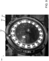
FIG. 9 is a diagrammatic, perspective view of a vertical roulette topper for the universal cabinet ofFIG. 1 . -
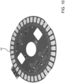
FIG. 10 is a diagrammatic, perspective view of a multifunctional board for the vertical roulette topper ofFIG. 9 . -
FIG. 11 is an illustration of an exemplary block diagram representing a general purpose computer system in which aspects of the methods and systems disclosed herein or portions thereof may be incorporated. - The present disclosure describes particular embodiments and their detailed construction and operation. The embodiments described herein are set forth by way of illustration only and not limitation. Those skilled in the art will recognize, in light of the teachings herein, that there may be a range of equivalents to the exemplary embodiments described herein. Most notably, other embodiments are possible, variations can be made to the embodiments described herein, and there may be equivalents to the components, parts, or steps that make up the described embodiments. For the sake of clarity and conciseness, certain aspects of components or steps of certain embodiments are presented without undue detail where such detail would be apparent to those skilled in the art in light of the teachings herein and/or where such detail would obfuscate an understanding of more pertinent aspects of the embodiments.
- Disclosed herein are methods, systems, and computer readable storage media that provide for increased guest satisfaction, game revenue generation and reduced maintenance costs. Some embodiments of the present invention are described herein in terms of a gaming cabinets for particular games for illustrative purposes. However, embodiments of the present invention are not limited to just the types of games described and may be implemented in various wagering systems - both automated and manual - that provide similar functionalities.
-
Figure 1 illustrates abase 100 for a universal cabinet for a variety of different games that may be connected to atop 101 of anupper section 102 of thebase 100. Thebase 100 may further include alower section 103 on which the upper section rests. As further illustrated inFigure 3 andFigure 4 , thebase 100 may include a number of exterior elements that provide visual and audio effects that serve to either attract attention to the game, so as to entice someone passing by to play a game offered by the universal cabinet, or to enhance the play of a game being played in the universal cabinet. - The exterior elements may include soft touch gel buttons, such as
buttons upper section 102 where a players arms would rest for extended periods of time, and acontrol button 110 that may be used for different games. Other lighting effects that may be provided includegel LED modules 112 of different sizes and shapes and anambient LED 114 that illuminates thebottom section 103 from underneath theupper section 102. Theupper section 102 may further include a money/credit/card receiving/payout mechanism 116 and adisplay 118.Speakers 120 in thelower section 103 may provide some or all of the sound, depending on the nature of the game being played. Afoot rest 122 may also be built into thelower section 102. - The inside of the universal cabinet may include a
controller module 200 that may provide common connections for each of the different types of toppers and provide a USB connection to an embedded computer (not shown) in thebottom section 103. The embedded computer may be a GANLOT AMDY-7005, which is designed for gaming applications. Thecontroller module 200 may also provide outputs for the base cabinet lighting and buttons, which makes it possible to offer numerous gaming machine lighting designs. Thecontroller module 200 may also make it possible to quickly change toppers on thebase 100. Only theupper section 102 may need to be removed to access thecontroller module 200. Connections from the existing topper may be disconnected and the topper removed from theupper section 102. The new topper may then be attached to theupper section 102 and its connections plugged into thecontroller module 200. In an embodiment, a switch in thecontroller module 200 may then be switched to correspond to the new topper. In other embodiments, the new topper can be identified by connecting or plugging one or more additional modules for that topper into thecontroller module 200 or changing a program of the embedded computer. This may make it possible to quickly change the type of game that is being played on theuniversal cabinet base 100 without have to remove thebase 100 from any row it is in and without moving other machines or forcing the other machines to be shut down. The may also make it possible to prototype and develop other toppers for new games, further reducing development and production costs. - As previously note,
Figure 3 andFigure 4 further illustrate thebase 100 of the universal cabinet when aseat 300 and a tallcurved display topper 302 have been connected. In addition to thespeakers 120 built into thelower section 103 of thebase 100, such as a 50 Watt/4 Ohm subwoofer speaker, theseat 300 may includeadditional speakers 402, such as two 25 Watt/8 Ohm speakers in anupper section 403 of theseat 300. Additional speakers may be included in thetopper 302, such as two 25 Watt/8Ohm speakers 408 at the top of thetopper 302 and two 25 Watt/8Ohm speakers 410 at the bottom of thetopper 302. In addition to those speakers, a 50 Watt/4Ohm rumble speaker 404 may be provided in thebottom section 405 of theseat 300. This many speakers may enable a variety of audio effects, especially if a range of speaker types are used, including tweeters, midranges and subwoofers or woofers. -
Figure 5 ,Figure 6 ,Figure 7 andFigure 8 illustrate different types of topper that may be added to the base 100 as previously discussed. These toppers include thedice topper 500 ofFigure 5 , which enables craps and similar types of dice games to be played. Thebase 100 includes a random generator (not shown) for controlling the randomness of the dice roll in order to make game fair. Even though the dice are being tossed as part of the game in the see-throughsection 502 of thedice topper 500, the game cycle speed may be just as fast as slot machine game cycles, thereby providing a different and more exciting form of a game with at least the same revenue potential as a slot machine being played for the same period of time. Depending on the type of game incorporated into the topper, thebase 100 may send random results for the game to the topper and in other cases the topper may send the random results to the bottom. For example, in the dice game, the resulting throw of the dice may be randomly effected by a random generator in the base, but the resulting throw cannot be predetermined so it has to be determined at the topper and then sent to thebase 100. -
Figure 6 illustrates to card game toppers, abaccarat topper 602 and ablackjack topper 604. Each of thecard mechanism 606, such as a SUZO card flipper module, may flip cards under control of the random generator. The card decks can be varied depending on the game, such as a classic deck with or without jokers, and cards including the back sides of cards so cards can be covered.Figure 7 illustrates adisplay card topper 700 where the display is wider than tall, which may allow higher resolution display.Figure 8 illustrates two different versions ofvertical roulette toppers Vertical roulette topper 802 includes aroulette wheel 804 andsignage 806 on top of theroulette wheel 804, whilevertical roulette topper 808 includes anadditional display 808 on top of which is mounted aroulette wheel 812 andsignage 814. - As illustrated in
Figure 9 andFigure 10 , thevertical roulette wheel 900 includes astationary roulette ball 902, which is shown mounted to a non-moving portion of thewheel 900 near the top, although other positions are possible. Since theroulette ball 902 does not move, the numbers do, which is accomplished by mounting a circular ring of numbers on a transparent ortranslucent number wheel 904 that is rotated based on the random generator of thebase 100. To simplify the electro-mechanics associated with rotating thenumber wheel 904, thenumber wheel 904 is sufficiently translucent thatLED lighting 906 provided behind the numbers is clearly visible. TheLED lighting 906 circuit board is illustrated inFigure 10 . The numbers themselves may be physically printed or attached to the number wheel so they can be illuminated by theLED lighting 906. In play, the random generator determines an amount of force to be applied to rotatenumber wheel 906 or the random generator determines when a breaking force will be applied to thenumber wheel 906 or a combination of both. - The present disclosure describes particular embodiments and their detailed construction and operation. The embodiments described herein are set forth by way of illustration only and not limitation. Those skilled in the art will recognize, in light of the teachings herein, that there may be a range of equivalents to the exemplary embodiments described herein. Most notably, other embodiments are possible, variations can be made to the embodiments described herein, and there may be equivalents to the components, parts, or steps that make up the described embodiments. For the sake of clarity and conciseness, certain aspects of components or steps of certain embodiments are presented without undue detail where such detail would be apparent to those skilled in the art in light of the teachings herein and/or where such detail would obfuscate an understanding of more pertinent aspects of the embodiments.
- The techniques described above can be implemented on a computing device associated with a gaming device (e.g., a gaming cabinet), a plurality of computing devices associated with a plurality of gaming devices, a controller in communication with the gaming device(s) (e.g., a controller configured to synchronize the gaming devices(s)), or a plurality of controllers in communication with the gaming device(s). Additionally, the techniques may be distributed between the computing device(s) and the controller(s).
Figure 11 illustrates an exemplary block diagram of a computing system that includes hardware modules, software module, and a combination thereof and that can be implemented as the computing device and/or as the server. - In a basic configuration, the computing system may include at least a processor, a system memory, a storage device, input/output peripherals, communication peripherals, and an interface bus. Instructions stored in the memory may be executed by the processor to perform a variety of methods and operations, including the shooter selection and console mirroring, as described above. The computing system components may be present in the gaming device, in a server or other component of a network, or distributed between some combinations of such devices.
- The interface bus is configured to communicate, transmit, and transfer data, controls, and commands between the various components of the electronic device. The system memory and the storage device comprise computer readable storage media, such as RAM, ROM, EEPROM, hard-drives, CD-ROMs, optical storage devices, magnetic storage devices, flash memory, and other tangible storage media. Any of such computer readable storage medium can be configured to store instructions or program codes embodying aspects of the disclosure. Additionally, the system memory comprises an operation system and applications. The processor is configured to execute the stored instructions and can comprise, for example, a logical processing unit, a microprocessor, a digital signal processor, and the like.
- The system memory and the storage device may also comprise computer readable signal media. A computer readable signal medium may include a propagated data signal with computer readable program code embodied therein. Such a propagated signal may take any of variety of forms including, but not limited to, electro-magnetic, optical, or any combination thereof. A computer readable signal medium may be any computer readable medium that is not a computer readable storage medium and that can communicate, propagate, or transport a program for use in connection with the computing system.
- Further, the input and output peripherals include user interfaces such as a keyboard, screen, microphone, speaker, other input/output devices, and computing components such as digital-to-analog and analog-to-digital converters, graphical processing units, serial ports, parallel ports, and universal serial bus. The input/output peripherals may also include a variety of sensors, such as light, proximity, GPS, magnetic field, altitude, and velocity/acceleration. RSSI, and distance sensors, as well as other types of sensors. The input/output peripherals may be connected to the processor through any of the ports coupled to the interface bus.
- The user interfaces can be configured to allow a user of the computing system to interact with the computing system. For example, the computing system may include instructions that, when executed, cause the computing system to generate a user interface and carry out other methods and operations that the user can use to provide input to the computing system and to receive an output from the computing system.
- This user interface may be in the form of a graphical user interface that is rendered at the screen and that is coupled with audio transmitted on the speaker and microphone and input received at the keyboard. In an embodiment, the user interface can be locally generated at the computing system. In another embodiment, the user interface may be hosted on a remote computing system and rendered at the computing system. For example, the server may generate the user interface and may transmit information related thereto to the computing device that, in tum, renders the user interface to the user. The computing device may, for example, execute a browser or an application that exposes an application program interface (API) at the server to access the user interface hosted on the server.
- Finally, the communication peripherals of the computing system are configured to facilitate communication between the computing system and other computing systems (e.g., between the computing device and the server) over a communications network. The communication peripherals include, for example, a network interface controller, modem, various modulators/demodulators and encoders/decoders, wireless and wired interface cards, antenna, and the like.
- The communication network includes a network of any type that is suitable for providing communications between the computing device and the server and may comprise a combination of discrete networks which may use different technologies. For example, the communications network includes a cellular network, a WiFi/ broadband network, a local area network (LAN), a wide area network (WAN), a telephony network, a fiber-optic network, or combinations thereof. In an example embodiment, the communication network includes the Internet and any networks adapted to communicate with the Internet. The communications network may be also configured as a means for transmitting data between the computing device and the server.
- The techniques described above may be embodied in, and fully or partially automated by, code modules executed by one or more computers or computer processors. The code modules may be stored on any type of non-transitory computer-readable medium or computer storage device, such as hard drives, solid state memory, optical disc, and/or the like. The processes and algorithms may be implemented partially or wholly in application-specific circuitry. The results of the disclosed processes and process steps may be stored, persistently or otherwise, in any type of non-transitory computer storage such as, e.g., volatile or non-volatile storage.
- As previously noted, the various features and processes described above may be used independently of one another, or may be combined in various ways. All possible combinations and sub- combinations are intended to fall within the scope of this disclosure. In addition, certain method or process blocks may be omitted in some implementations. The methods and processes described herein are also not limited to any particular sequence, and the blocks or states relating thereto can be performed in other sequences that are appropriate. For example, described blocks or states may be performed in an order other than that specifically disclosed, or multiple blocks or states may be combined in a single block or state. The example blocks or states may be performed in serial, in parallel, or in some other manner. Blocks or states may be added to or removed from the disclosed example embodiments. The example systems and components described herein may be configured differently than described. For example, elements may be added to, removed from, or rearranged compared to the disclosed example embodiments.
- Conditional language used herein, such as, among others, "can," "could," "might," "may," "e.g.," and the like, unless specifically stated otherwise, or otherwise understood within the context as used, is generally intended to convey that certain embodiments include, while other embodiments do not include, certain features, elements, and/or steps. Thus, such conditional language is not generally intended to imply that features, elements and/or steps are in any way required for one or more embodiments or that one or more embodiments necessarily include logic for deciding, with or without author input or prompting, whether these features, elements and/or steps are included or are to be performed in any particular embodiment. The terms "comprising," "including," "having," and the like are synonymous and are used inclusively, in an open-ended fashion, and do not exclude additional elements, features, acts, operations, and so forth. Also, the term "or" is used in its inclusive sense (and not in its exclusive sense) so that when used, for example, to connect a list of elements, the term "or" means one, some, or all of the elements in the list.
- The present disclosure describes particular embodiments and their detailed construction and operation. The embodiments described herein are set forth by way of illustration only and not limitation. Those skilled in the art will recognize, in light of the teachings herein, that there may be a range of equivalents to the exemplary embodiments described herein. Most notably, other embodiments are possible, variations can be made to the embodiments described herein, and there may be equivalents to the components, parts, or steps that make up the described embodiments. For the sake of clarity and conciseness, certain aspects of components or steps of certain embodiments are presented without undue detail where such detail would be apparent to those skilled in the art in light of the teachings herein and/or where such detail would obfuscate an understanding of more pertinent aspects of the embodiments.
- The terms and descriptions used above are set forth by way of illustration only and are not meant as limitations. Those skilled in the art will recognize that those and many other variations, enhancements and modifications of the concepts described herein are possible without departing from the underlying principles of the invention. The scope of the invention should therefore be determined only by the following claims and their equivalents.
Claims (9)
- A vertical roulette mechanism, comprising:a stand;a transparent or translucent wheel (804; 900) configured to be mounted to the stand, the wheel (804; 900) including a circular ring of a plurality of numbers corresponding to a movable roulette wheel (904);
a motor affixed to the stand and configured to rotate and brake the movable roulette wheel (904) while the stand remains stationary;a stationary roulette ball (902) fixedly mounted to the stand;a plurality of lights (906) fixedly mounted to the stand between the stand and the wheel (900) and behind each of the plurality of numbers, the plurality of lights configured to illuminate the wheel so the numbers are visible to a player of the vertical roulette mechanism; anda base section (100) including a controller module (200) and a computer module, the controller module (200) including a plurality of connectors, the base section (100) including an interactive display and one or more buttons configured to enable a player to interact with a roulette game at least partially displayed on the display, the wheel and the plurality of lights including connectors configured to mate with the plurality of connectors;the base section further comprising a random number generator that determines an amount of force to be applied to rotate the movable roulette wheel or when a braking force will be applied to the movable roulette wheel or a combination of both. - The vertical roulette mechanism as recited in claim 1, wherein the base section (100) further includes one or more lights and one or more speakers.
- The vertical roulette mechanism as recited in claim 1, wherein the base section (100) further includes a money/credit/card receiving/payout mechanism.
- The vertical roulette mechanism as recited in claim 1, wherein the base section (100) is configured to transmit randomly generated control signals to the motor to cause the movable roulette wheel (904) to rotate as part of the roulette game.
- The vertical roulette mechanism as recited in claim 4, further comprising a braking mechanism for braking the movable roulette wheel (904) when it is rotating, the base section further configured to transmit randomly generated control signals to the braking mechanism to cause the wheel (904) to stop rotating as part of the roulette game.
- The vertical roulette mechanism as recited in claim 1, wherein rotation of the movable roulette wheel (904) and illumination of the plurality of lights simulates the fixedly mounted roulette ball (902) spinning around the movable roulette wheel of a horizontal roulette wheel.
- The vertical roulette mechanism as recited in claim 6, wherein the roulette ball (902) is fixedly mounted near to the top of the wheel.
- The vertical roulette mechanism as recited in claim 1, wherein the base section (100) includes an upper section (102) and a lower section (103) and the display is positioned in the upper section (102).
- The vertical roulette mechanism as recited in claim 1, further comprising a seat for a single player connected to the stand, wherein the vertical roulette mechanism occupies a space equivalent to a slot machine cabinet.
Priority Applications (1)
| Application Number | Priority Date | Filing Date | Title |
|---|---|---|---|
| HRP20250483TT HRP20250483T1 (en) | 2017-10-06 | 2018-10-05 | A vertical roulette mechanism |
Applications Claiming Priority (2)
| Application Number | Priority Date | Filing Date | Title |
|---|---|---|---|
| US201762569128P | 2017-10-06 | 2017-10-06 | |
| PCT/US2018/054755 WO2019071231A2 (en) | 2017-10-06 | 2018-10-05 | VERTICAL ROLLER MECHANISM |
Publications (4)
| Publication Number | Publication Date |
|---|---|
| EP3691761A2 EP3691761A2 (en) | 2020-08-12 |
| EP3691761A4 EP3691761A4 (en) | 2021-07-21 |
| EP3691761C0 EP3691761C0 (en) | 2025-03-26 |
| EP3691761B1 true EP3691761B1 (en) | 2025-03-26 |
Family
ID=65993325
Family Applications (1)
| Application Number | Title | Priority Date | Filing Date |
|---|---|---|---|
| EP18864558.4A Active EP3691761B1 (en) | 2017-10-06 | 2018-10-05 | A vertical roulette mechanism |
Country Status (8)
| Country | Link |
|---|---|
| US (1) | US10854037B2 (en) |
| EP (1) | EP3691761B1 (en) |
| CA (1) | CA3078618A1 (en) |
| ES (1) | ES3024834T3 (en) |
| HR (1) | HRP20250483T1 (en) |
| PH (1) | PH12020550224B1 (en) |
| SG (1) | SG11202003144QA (en) |
| WO (1) | WO2019071231A2 (en) |
Families Citing this family (1)
| Publication number | Priority date | Publication date | Assignee | Title |
|---|---|---|---|---|
| US11443585B2 (en) | 2019-10-11 | 2022-09-13 | Interblock D.D. | Vertical roulette mechanism with rotating rim |
Citations (16)
| Publication number | Priority date | Publication date | Assignee | Title |
|---|---|---|---|---|
| DE4200496A1 (en) | 1991-01-15 | 1992-07-16 | Spielbank Mainz Trier Bad Ems | Lottery or game of change machine - has wheel with stopping cycle determined by insertion of spring arm in pseudo-random cycle |
| US5785594A (en) | 1996-12-03 | 1998-07-28 | H. Betti Industries, Inc. | Spinning wheel amusement device |
| DE19748194A1 (en) | 1997-10-31 | 1999-05-06 | Nsm Ag | Coin operated amusement machine |
| US20040150161A1 (en) | 2003-01-31 | 2004-08-05 | Dragon Co., Ltd. | Symbol display device for game machine |
| US20060119036A1 (en) | 2004-11-19 | 2006-06-08 | Spin Time Usa, Llc | Spinning wheel promotional and advertising game in a retail establishment |
| US20100120488A1 (en) | 2007-02-01 | 2010-05-13 | Yevgen Savytskyy | Amusement and gaming machines |
| EP2357622A1 (en) | 2010-01-15 | 2011-08-17 | adp Gauselmann GmbH | Method for operating a gaming device of an entertainment device |
| US20120315985A1 (en) | 2011-06-13 | 2012-12-13 | Wms Gaming Inc. | Convertible gaming chairs and wagering game systems and machines with a convertible gaming chair |
| US20120322564A1 (en) | 2011-06-14 | 2012-12-20 | Wms Gaming Inc. | Gaming Machine Having Chair With Modular Back Panel |
| US20130307216A1 (en) | 2009-10-27 | 2013-11-21 | Mark H. Jones | Rotary card shuffling machine |
| US20140221073A1 (en) | 2013-02-01 | 2014-08-07 | Pockaj D.O.O. (d/b/a Alfastreet) | Bingo game system with wheel game simulation feature |
| WO2015107356A1 (en) | 2014-01-16 | 2015-07-23 | Central Gaming Limited | Gaming apparatus |
| US20160027239A1 (en) | 2010-11-10 | 2016-01-28 | Universal Entertainment Corporation | Gaming Machine |
| US20170109960A1 (en) | 2010-11-10 | 2017-04-20 | Universal Entertainment Corporation | Gaming machine |
| US20170109961A1 (en) | 2014-06-27 | 2017-04-20 | Novomatic Ag | Gaming device comprising a rotatable game wheel |
| DE202018102391U1 (en) | 2018-04-29 | 2018-05-17 | Çahit Bulut | Device for a game of skill |
-
2018
- 2018-10-05 HR HRP20250483TT patent/HRP20250483T1/en unknown
- 2018-10-05 SG SG11202003144QA patent/SG11202003144QA/en unknown
- 2018-10-05 CA CA3078618A patent/CA3078618A1/en active Pending
- 2018-10-05 EP EP18864558.4A patent/EP3691761B1/en active Active
- 2018-10-05 WO PCT/US2018/054755 patent/WO2019071231A2/en not_active Ceased
- 2018-10-05 ES ES18864558T patent/ES3024834T3/en active Active
- 2018-10-05 PH PH1/2020/550224A patent/PH12020550224B1/en unknown
- 2018-10-05 US US16/153,162 patent/US10854037B2/en active Active
Patent Citations (16)
| Publication number | Priority date | Publication date | Assignee | Title |
|---|---|---|---|---|
| DE4200496A1 (en) | 1991-01-15 | 1992-07-16 | Spielbank Mainz Trier Bad Ems | Lottery or game of change machine - has wheel with stopping cycle determined by insertion of spring arm in pseudo-random cycle |
| US5785594A (en) | 1996-12-03 | 1998-07-28 | H. Betti Industries, Inc. | Spinning wheel amusement device |
| DE19748194A1 (en) | 1997-10-31 | 1999-05-06 | Nsm Ag | Coin operated amusement machine |
| US20040150161A1 (en) | 2003-01-31 | 2004-08-05 | Dragon Co., Ltd. | Symbol display device for game machine |
| US20060119036A1 (en) | 2004-11-19 | 2006-06-08 | Spin Time Usa, Llc | Spinning wheel promotional and advertising game in a retail establishment |
| US20100120488A1 (en) | 2007-02-01 | 2010-05-13 | Yevgen Savytskyy | Amusement and gaming machines |
| US20130307216A1 (en) | 2009-10-27 | 2013-11-21 | Mark H. Jones | Rotary card shuffling machine |
| EP2357622A1 (en) | 2010-01-15 | 2011-08-17 | adp Gauselmann GmbH | Method for operating a gaming device of an entertainment device |
| US20160027239A1 (en) | 2010-11-10 | 2016-01-28 | Universal Entertainment Corporation | Gaming Machine |
| US20170109960A1 (en) | 2010-11-10 | 2017-04-20 | Universal Entertainment Corporation | Gaming machine |
| US20120315985A1 (en) | 2011-06-13 | 2012-12-13 | Wms Gaming Inc. | Convertible gaming chairs and wagering game systems and machines with a convertible gaming chair |
| US20120322564A1 (en) | 2011-06-14 | 2012-12-20 | Wms Gaming Inc. | Gaming Machine Having Chair With Modular Back Panel |
| US20140221073A1 (en) | 2013-02-01 | 2014-08-07 | Pockaj D.O.O. (d/b/a Alfastreet) | Bingo game system with wheel game simulation feature |
| WO2015107356A1 (en) | 2014-01-16 | 2015-07-23 | Central Gaming Limited | Gaming apparatus |
| US20170109961A1 (en) | 2014-06-27 | 2017-04-20 | Novomatic Ag | Gaming device comprising a rotatable game wheel |
| DE202018102391U1 (en) | 2018-04-29 | 2018-05-17 | Çahit Bulut | Device for a game of skill |
Non-Patent Citations (3)
| Title |
|---|
| ANONYMOUS: "TEST REPORT IEC 60335-2-82 Household and similar electrical appliances -Safety Part 2-82: Particular requirements for amusement machines and personal service machines", IEC/IECEE, 12 June 2014 (2014-06-12), XP093356371 |
| D19 - THREE INVOICES 13/0257, 15/0164, 15/0072 REGARDING SALES OF ALFASTREET’S WHEEL OF FORTUNE (PRICE INFORMATION BLACKENED-OUT) |
| D20 - Video of the lighting in ALFASTREET’s Wheel of Fortune |
Also Published As
| Publication number | Publication date |
|---|---|
| WO2019071231A8 (en) | 2020-05-22 |
| EP3691761C0 (en) | 2025-03-26 |
| US10854037B2 (en) | 2020-12-01 |
| EP3691761A2 (en) | 2020-08-12 |
| PH12020550224B1 (en) | 2023-12-06 |
| PH12020550224A1 (en) | 2021-02-15 |
| CA3078618A1 (en) | 2019-04-11 |
| WO2019071231A2 (en) | 2019-04-11 |
| SG11202003144QA (en) | 2020-05-28 |
| ES3024834T3 (en) | 2025-06-05 |
| US20190108718A1 (en) | 2019-04-11 |
| WO2019071231A3 (en) | 2019-10-24 |
| HRP20250483T1 (en) | 2025-08-01 |
| EP3691761A4 (en) | 2021-07-21 |
Similar Documents
| Publication | Publication Date | Title |
|---|---|---|
| US11854342B2 (en) | Gaming cabinet with universal connection for mechanical game topper | |
| CA3078620C (en) | Roulette game cycle optimization and methods for synchronizing game cycles of double roulette wheels | |
| CN106659931A (en) | Game system, player tracking device, gaming machine, and program | |
| TW202529054A (en) | Dual play universal cabinet | |
| US20240265784A1 (en) | Roulette game and side bets with double roulette wheels | |
| EP3691761B1 (en) | A vertical roulette mechanism | |
| US11443585B2 (en) | Vertical roulette mechanism with rotating rim | |
| US10629027B2 (en) | Roulette game cycle optimization and methods for estimating a bet close time | |
| US20190108725A1 (en) | Roulette game cycle optimization and methods for placing bets during a roulette game cycle | |
| US20250006011A1 (en) | Live gaming apparatus with dice shaker and gaming wheel | |
| CA3078621C (en) | Roulette game cycle optimization and methods for adjusting a roulette wheel rotation speed | |
| US20190108722A1 (en) | Roulette game cycle optimization and methods for adjusting a roulette ball launch speed | |
| TWI914851B (en) | Massively parallel real-time remote gameplay systems and methods | |
| US20240386777A1 (en) | Remote gaming device operations using live video streams | |
| US20250006010A1 (en) | Massively parallel real-time remote gameplay | |
| CN121419819A (en) | Game pods offering real-time remote gameplay | |
| US20240265765A1 (en) | Roulette rim visual display for gaming systems | |
| TW202426098A (en) | Roulette system with a bonus event |
Legal Events
| Date | Code | Title | Description |
|---|---|---|---|
| REG | Reference to a national code |
Ref country code: HR Ref legal event code: TUEP Ref document number: P20250483T Country of ref document: HR |
|
| STAA | Information on the status of an ep patent application or granted ep patent |
Free format text: STATUS: THE INTERNATIONAL PUBLICATION HAS BEEN MADE |
|
| PUAI | Public reference made under article 153(3) epc to a published international application that has entered the european phase |
Free format text: ORIGINAL CODE: 0009012 |
|
| STAA | Information on the status of an ep patent application or granted ep patent |
Free format text: STATUS: REQUEST FOR EXAMINATION WAS MADE |
|
| 17P | Request for examination filed |
Effective date: 20200505 |
|
| AK | Designated contracting states |
Kind code of ref document: A2 Designated state(s): AL AT BE BG CH CY CZ DE DK EE ES FI FR GB GR HR HU IE IS IT LI LT LU LV MC MK MT NL NO PL PT RO RS SE SI SK SM TR |
|
| AX | Request for extension of the european patent |
Extension state: BA ME |
|
| DAV | Request for validation of the european patent (deleted) | ||
| DAX | Request for extension of the european patent (deleted) | ||
| A4 | Supplementary search report drawn up and despatched |
Effective date: 20210618 |
|
| RIC1 | Information provided on ipc code assigned before grant |
Ipc: A63F 5/00 20060101AFI20210614BHEP Ipc: A63F 5/02 20060101ALI20210614BHEP Ipc: A63F 5/04 20060101ALI20210614BHEP Ipc: A63F 9/00 20060101ALI20210614BHEP Ipc: G07F 17/32 20060101ALI20210614BHEP |
|
| RAP3 | Party data changed (applicant data changed or rights of an application transferred) |
Owner name: INTERBLOCK D.O.O. |
|
| 111Z | Information provided on other rights and legal means of execution |
Free format text: AL AT BE BG CH CY CZ DE DK EE ES FI FR GB GR HR HU IE IS IT LT LU LV MC MK MT NL NO PL PT RO RS SE SI SK SM TR Effective date: 20230309 |
|
| STAA | Information on the status of an ep patent application or granted ep patent |
Free format text: STATUS: EXAMINATION IS IN PROGRESS |
|
| P01 | Opt-out of the competence of the unified patent court (upc) registered |
Effective date: 20230528 |
|
| 17Q | First examination report despatched |
Effective date: 20230615 |
|
| GRAP | Despatch of communication of intention to grant a patent |
Free format text: ORIGINAL CODE: EPIDOSNIGR1 |
|
| STAA | Information on the status of an ep patent application or granted ep patent |
Free format text: STATUS: GRANT OF PATENT IS INTENDED |
|
| INTG | Intention to grant announced |
Effective date: 20240624 |
|
| 111Z | Information provided on other rights and legal means of execution |
Free format text: AL AT BE BG CH CY CZ DE DK EE ES FI FR GB GR HR HU IE IS IT LT LU LV MC MK MT NL NO PL PT RO RS SE SI SK SM TR Effective date: 20230309 |
|
| GRAJ | Information related to disapproval of communication of intention to grant by the applicant or resumption of examination proceedings by the epo deleted |
Free format text: ORIGINAL CODE: EPIDOSDIGR1 |
|
| STAA | Information on the status of an ep patent application or granted ep patent |
Free format text: STATUS: EXAMINATION IS IN PROGRESS |
|
| INTC | Intention to grant announced (deleted) | ||
| GRAP | Despatch of communication of intention to grant a patent |
Free format text: ORIGINAL CODE: EPIDOSNIGR1 |
|
| STAA | Information on the status of an ep patent application or granted ep patent |
Free format text: STATUS: GRANT OF PATENT IS INTENDED |
|
| INTG | Intention to grant announced |
Effective date: 20241203 |
|
| GRAS | Grant fee paid |
Free format text: ORIGINAL CODE: EPIDOSNIGR3 |
|
| GRAA | (expected) grant |
Free format text: ORIGINAL CODE: 0009210 |
|
| STAA | Information on the status of an ep patent application or granted ep patent |
Free format text: STATUS: THE PATENT HAS BEEN GRANTED |
|
| AK | Designated contracting states |
Kind code of ref document: B1 Designated state(s): AL AT BE BG CH CY CZ DE DK EE ES FI FR GB GR HR HU IE IS IT LI LT LU LV MC MK MT NL NO PL PT RO RS SE SI SK SM TR |
|
| REG | Reference to a national code |
Ref country code: GB Ref legal event code: FG4D |
|
| REG | Reference to a national code |
Ref country code: CH Ref legal event code: EP |
|
| REG | Reference to a national code |
Ref country code: DE Ref legal event code: R096 Ref document number: 602018080557 Country of ref document: DE |
|
| REG | Reference to a national code |
Ref country code: IE Ref legal event code: FG4D |
|
| U01 | Request for unitary effect filed |
Effective date: 20250416 |
|
| P04 | Withdrawal of opt-out of the competence of the unified patent court (upc) registered |
Free format text: CASE NUMBER: APP_19007/2025 Effective date: 20250421 |
|
| U07 | Unitary effect registered |
Designated state(s): AT BE BG DE DK EE FI FR IT LT LU LV MT NL PT RO SE SI Effective date: 20250424 |
|
| REG | Reference to a national code |
Ref country code: ES Ref legal event code: FG2A Ref document number: 3024834 Country of ref document: ES Kind code of ref document: T3 Effective date: 20250605 |
|
| PG25 | Lapsed in a contracting state [announced via postgrant information from national office to epo] |
Ref country code: RS Free format text: LAPSE BECAUSE OF FAILURE TO SUBMIT A TRANSLATION OF THE DESCRIPTION OR TO PAY THE FEE WITHIN THE PRESCRIBED TIME-LIMIT Effective date: 20250626 |
|
| PG25 | Lapsed in a contracting state [announced via postgrant information from national office to epo] |
Ref country code: GR Free format text: LAPSE BECAUSE OF FAILURE TO SUBMIT A TRANSLATION OF THE DESCRIPTION OR TO PAY THE FEE WITHIN THE PRESCRIBED TIME-LIMIT Effective date: 20250627 |
|
| REG | Reference to a national code |
Ref country code: HR Ref legal event code: T1PR Ref document number: P20250483 Country of ref document: HR |
|
| PG25 | Lapsed in a contracting state [announced via postgrant information from national office to epo] |
Ref country code: SM Free format text: LAPSE BECAUSE OF FAILURE TO SUBMIT A TRANSLATION OF THE DESCRIPTION OR TO PAY THE FEE WITHIN THE PRESCRIBED TIME-LIMIT Effective date: 20250326 |
|
| PG25 | Lapsed in a contracting state [announced via postgrant information from national office to epo] |
Ref country code: PL Free format text: LAPSE BECAUSE OF FAILURE TO SUBMIT A TRANSLATION OF THE DESCRIPTION OR TO PAY THE FEE WITHIN THE PRESCRIBED TIME-LIMIT Effective date: 20250326 |
|
| PG25 | Lapsed in a contracting state [announced via postgrant information from national office to epo] |
Ref country code: SK Free format text: LAPSE BECAUSE OF FAILURE TO SUBMIT A TRANSLATION OF THE DESCRIPTION OR TO PAY THE FEE WITHIN THE PRESCRIBED TIME-LIMIT Effective date: 20250326 |
|
| PG25 | Lapsed in a contracting state [announced via postgrant information from national office to epo] |
Ref country code: IS Free format text: LAPSE BECAUSE OF FAILURE TO SUBMIT A TRANSLATION OF THE DESCRIPTION OR TO PAY THE FEE WITHIN THE PRESCRIBED TIME-LIMIT Effective date: 20250726 |
|
| PGFP | Annual fee paid to national office [announced via postgrant information from national office to epo] |
Ref country code: GB Payment date: 20251229 Year of fee payment: 8 |
|
| PLBI | Opposition filed |
Free format text: ORIGINAL CODE: 0009260 |
|
| PGFP | Annual fee paid to national office [announced via postgrant information from national office to epo] |
Ref country code: NO Payment date: 20251231 Year of fee payment: 8 Ref country code: MC Payment date: 20251222 Year of fee payment: 8 |
|
| PLAX | Notice of opposition and request to file observation + time limit sent |
Free format text: ORIGINAL CODE: EPIDOSNOBS2 |
|
| REG | Reference to a national code |
Ref country code: CH Ref legal event code: L10 Free format text: ST27 STATUS EVENT CODE: U-0-0-L10-L00 (AS PROVIDED BY THE NATIONAL OFFICE) Effective date: 20260114 |
|
| PLAF | Information modified related to communication of a notice of opposition and request to file observations + time limit |
Free format text: ORIGINAL CODE: EPIDOSCOBS2 |
|
| PG25 | Lapsed in a contracting state [announced via postgrant information from national office to epo] |
Ref country code: CZ Free format text: LAPSE BECAUSE OF FAILURE TO SUBMIT A TRANSLATION OF THE DESCRIPTION OR TO PAY THE FEE WITHIN THE PRESCRIBED TIME-LIMIT Effective date: 20250326 |
|
| REG | Reference to a national code |
Ref country code: HR Ref legal event code: ODRP Ref document number: P20250483 Country of ref document: HR Payment date: 20251229 Year of fee payment: 8 |
|
| U21 | Renewal fee for the european patent with unitary effect paid with additional fee |
Year of fee payment: 8 Effective date: 20251229 |
|
| 26 | Opposition filed |
Opponent name: POCKAJ D.O.O. Effective date: 20251229 |